1. Introduction
In the past few years, wind energy has becoming an important power source in countries’ energy matrices. This technology has been continually developed and, nowadays, the wind generators have increased their power capability and, consequently, their impacts in the grid have become more relevant. Among wind turbine technologies, the Doubly Fed Induction Generator (DFIG) is one of the most used in wind farms all over the world [
1,
2].
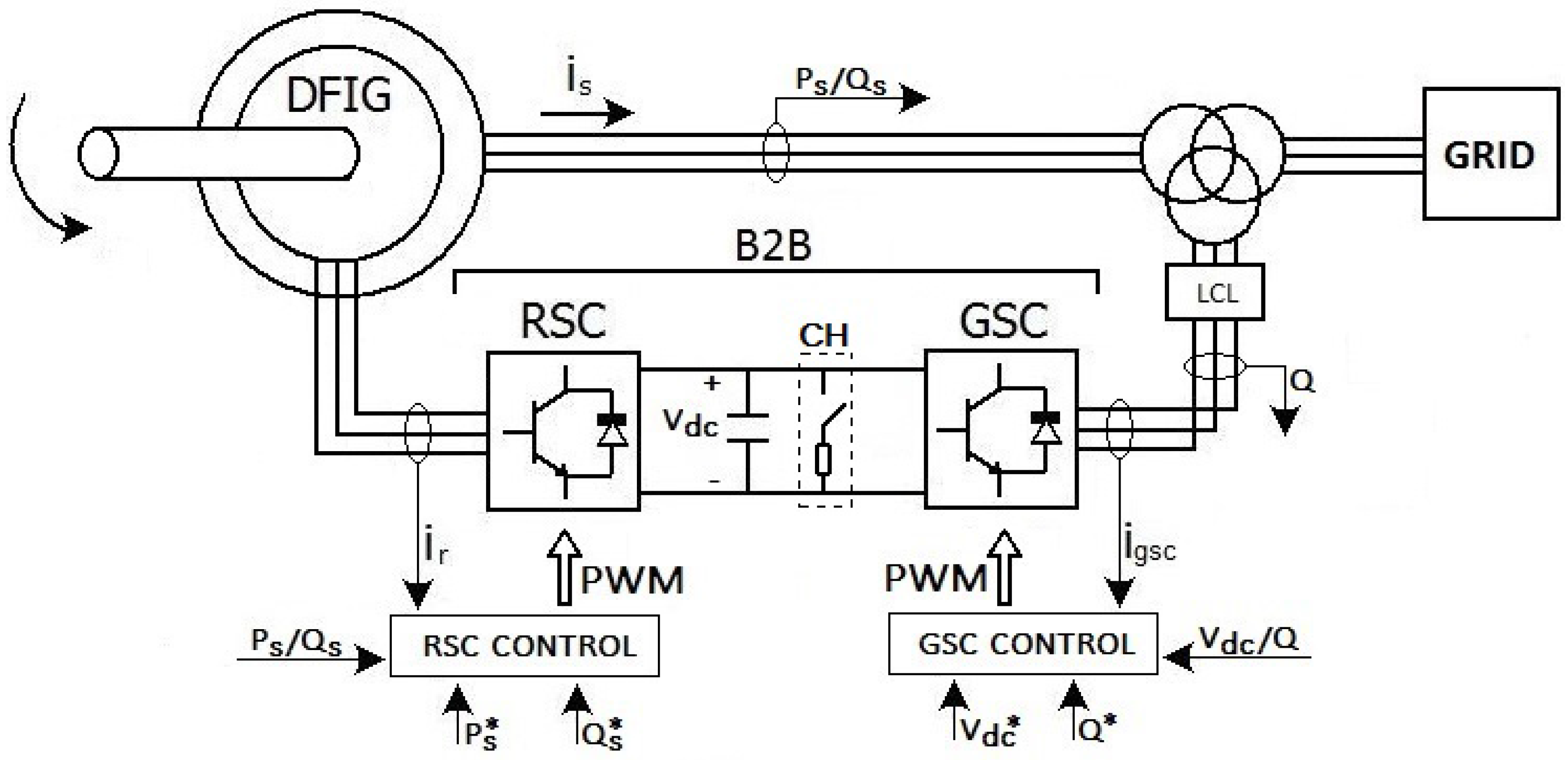
The DFIG stator is directly connected to a grid, while its rotor is connected to a grid through a back-to-back converter (B2B) and a third-order LCL filter.
Figure 1 shows a DFIG structure with some conventions used in this paper: GSC is Grid Side Converter, RSC is Rotor Side Converter,
is stator current,
is GSC AC current,
is rotor current and an LCL is a high-order passive filter. The GSC converter controls DC-link Voltage (
) and the reactive power (
Q) between grid and B2B. The DC-link chopper (CH) is a simple protection device that shorts the DC-link through a power resistor when the DC-link voltage exceeds a fixed threshold. The RSC converter controls active power (
) and reactive (
) power between the machine stator and the grid.
Figure 1.
DFIG Structure.
Figure 1.
DFIG Structure.
Research involving DFIG is worried about its effects into the electric system and about the impacts of grid disturbances in DFIG [
3,
4]. Nowadays, with the increased penetration of wind turbines in electric system, the grid codes understand that the generators have to contribute with the system stability. Each code establishes its own requirements about grid disturbances that the sources must withstand [
5].
One of the main issues concerning DFIG is low voltage ride-through supportability [
6,
7,
8,
9]. When a fault occurs, high currents are induced in the rotor and torque oscillations appear in the machine. These behaviors can damage the DFIG system.
In the rotor circuit, a severe voltage dip can generate, in per-unit quantities, rotor currents as high as 3.0 pu to 5.0 pu if no protection is provided. A common protection circuit makes use of a resistance bank, named crowbar, that is inserted into the rotor output and activated whenever a fault occurs [
10]. This solution provides an alternative path to rotor currents protecting the B2B converter. Its major disadvantage is that the DFIG loses its controllability once the crowbar is triggered, due to the rotor side converter deactivating [
11]. In such a situation, the DFIG absorbs a large amount of reactive power from the grid, leading to further grid voltage degradation [
4].
Other strategies have been proposed using a superconducting resistive current limiter (SCL) between DFIG and grid [
12,
13]. It reduces fault current level at the stator side and improves the fault ride-through capability of the system. However, as it is placed at the connection point, its implementation should consider the whole power of DFIG.
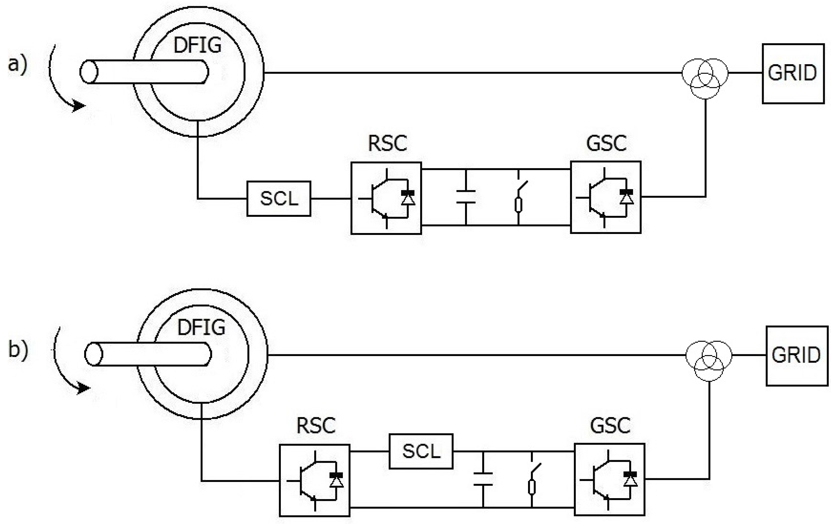
This paper proposes a novel solution for DFIG LVRT using an SCL in two arrangements: one, the SCL is placed between the machine rotor and the RSC, named three-phase SCL, and another placed in the converter DC-link, named DC SCL, as shown in
Figure 2. The performance of each solution is evaluated using the simulation tool PSCAD™/EMTDC™. In order to provide normalization, all tests were done under the IEC (International Electrotechnical Commission) 61400 wind turbine standards [
14], adopted by most manufacturers and publications in the area [
3,
15,
16].
Figure 2.
Proposed DFIG Structure: (a) with three-phase SCL and (b) with DC SCL.
Figure 2.
Proposed DFIG Structure: (a) with three-phase SCL and (b) with DC SCL.
2. Dynamic Doubly Fed Induction Generator (DFIG) dq Model
The induction machine model [
17,
18,
19] used in the simulation analysis performed is as follows.
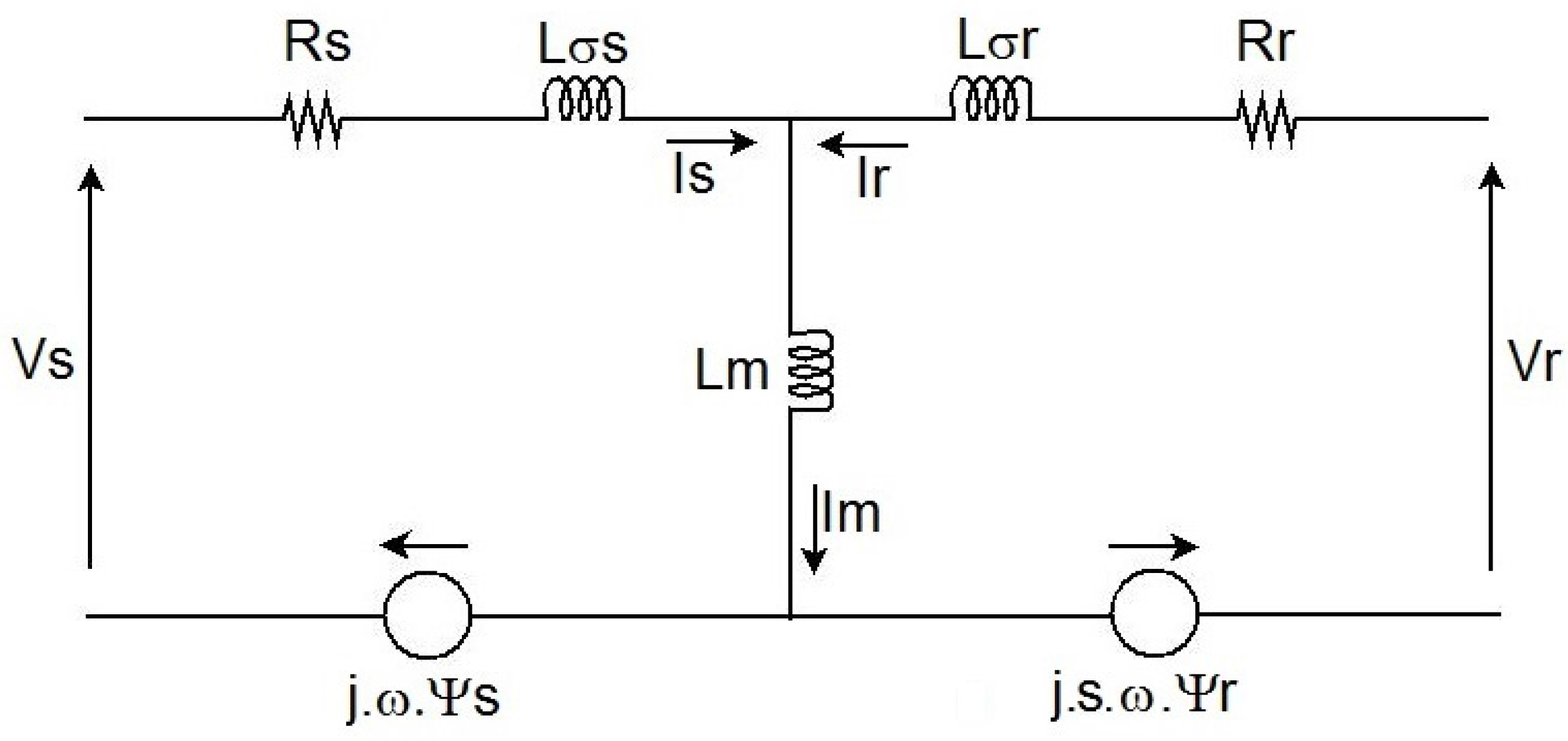
Figure 3 shows the equivalent DFIG dq circuit in the synchronous reference frame with adopted conventions. The dq model can be described by Equations (1)–(6) [
20], the rotor variables are referred to stator side.
Figure 3.
Equivalent DFIG circuit in the synchronous reference frame.
Figure 3.
Equivalent DFIG circuit in the synchronous reference frame.
where
is stator phase voltage,
is stator resistance,
is stator flux,
is stator current,
ω is synchronous angular frequency,
is rotor phase voltage,
is rotor resistance,
is rotor flux,
is rotor current,
s is slip,
is magnetizing inductance,
is stator leakage inductance and
is rotor leakage inductance. The parameters used in simulations are given in
Table 1.
Table 1.
Wind turbine system simulation parameters.
Table 1.
Wind turbine system simulation parameters.
| Nominal Values of the Induction Generator |
|---|
| Nominal power | 2.0 MW |
| Stator line voltage | 690 V |
| Rated stator current | 1760 A |
| Rated speed | 1500 RPM |
| Stator to rotor turn ratio | 0.3333 (Y/Y) |
| Magnetizing inductance | 2.5 mH |
| Stator leakage inductance | 0.087 mH |
| Rotor leakage inductance | 0.783 mH |
| Stator resistance | 2.6 mΩ |
| Rotor resistance | 26.1 mΩ |
| DC-link capacitor | 50 mF |
| DC-link voltage | 1.0 kV |
| GSC line voltage | 400 V |
3. Doubly Fed Induction Generator (DFIG) Behavior under Voltage Dips
During a severe voltage dip, as the flux cannot vary suddenly due to the associated stored energy, a transient flux (natural flux) appears, and a high value transient voltage is induced in the rotor terminals. The machine is demagnetized from prior steady-state flux to its new value (forced flux), which is proportional to the new stator voltage.
The stator flux behavior can be achieved from its dynamic vector expression, as stated by Equation (7) [
20].
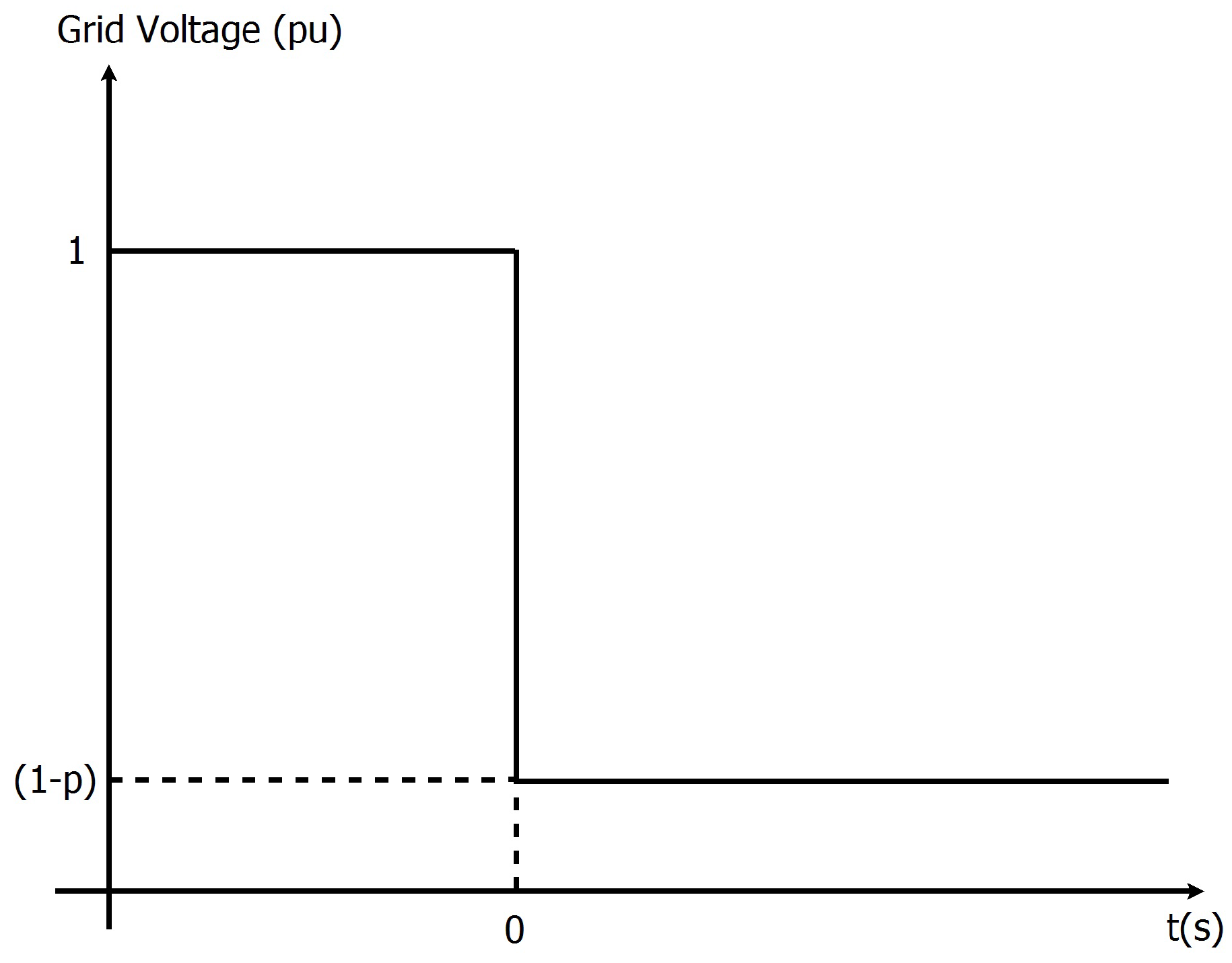
The generator is initially considered at normal operation and, at 0
s, a voltage dip occurs with depth
p, as shown in
Figure 4. Equation (8) describes this situation.
is the grid peak voltage at normal operation.
The LVRT adopted strategy inserts a resistance into the rotor circuit during voltage dip. is the total impedance seen by stator of the machine at this condition.
When the voltage dip occurs, the stator flux has its dynamic described by Equation (9)
where
The Electromagnetic Force (
) induced in the rotor is the sum of two terms,
e
, Equation (11). The first term,
, is due to grid voltage, shown in Equation (12). The second term,
, shown in Equation (13), is a transient voltage originated by natural flux with time constant
,
where
The rotor current, referred to the stator, can be obtained using Equation (14).
4. Resistive Superconducting Current Limiter (SCL)
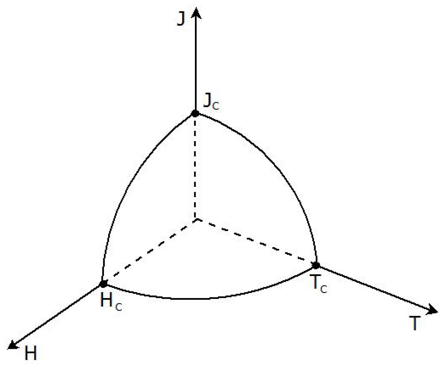
Some materials, named superconductors, present the characteristic of null resistance under certain operational conditions, named critical temperature (
), critical current density (
) and critical magnetic field (
) (
Figure 5) [
21]. Whenever one or more of such parameters increases above critical limits, the superconductor makes a transition from superconducting to normal state. Several implementations using SCL have already been made in applications such as prototypes [
22] and commercial application [
23,
24], distribution grids [
25] and motor start [
26].
Applying an SCL may achieve prospective benefits and operation cost savings, considering factors such as increase of system reliability and reduction of expected fault current, as was demonstrated by [
13].
A resistive type SCL is based on this transition from superconducting to normal state, which is called the quenching process. The SCL behavior can be characterized by a resistance transition in terms of temperature (
T) and current density (
J) as described by Equation (15) [
22,
27].
is the critical current density,
is the critical temperature and
n the exponent of
E-
J power law relation [
28].
Figure 5.
Three-dimensional surface defined by temperature (T) magnetic field (H) and current density (J).
Figure 5.
Three-dimensional surface defined by temperature (T) magnetic field (H) and current density (J).
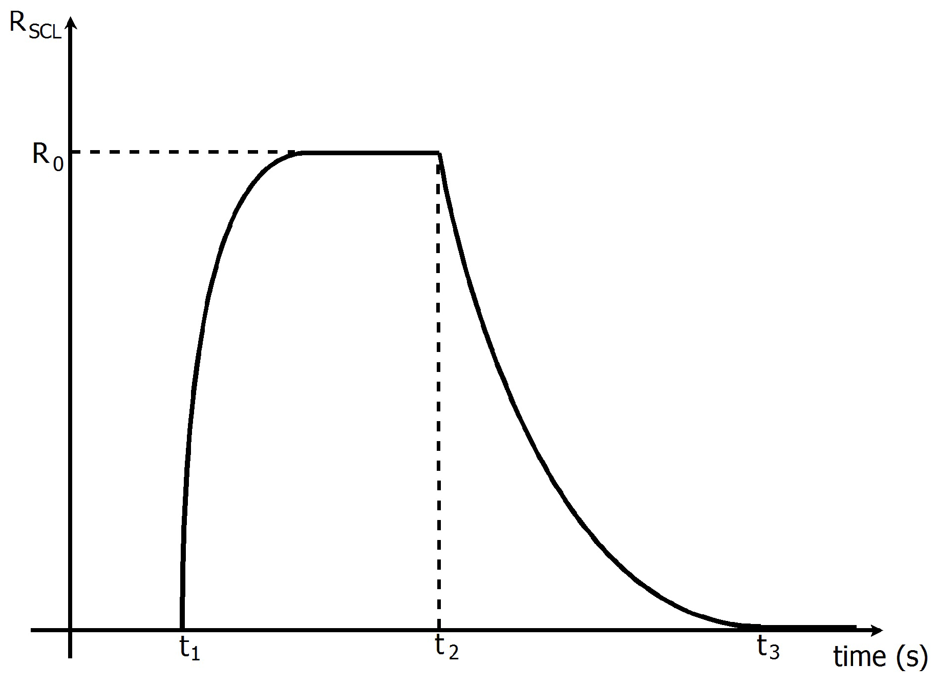
The resistive behavior of SCL can also be represented by a time-variant resistance [
29,
30,
31], as described by Equation (16). This is the model adopted by this paper.
Figure 6 shows this behavior. At time
, the SCL changes from superconducting state to quenching state, and its resistance increases exponentially.
is the maximum SCL resistance and
is the time constant of quenching state. This paper adopts the transition time from the superconducting to normal state,
, equal 1 ms [
29,
31,
32]. After time
, the currents fall below their critical value and the SCL is able to return to superconducting state as long as its temperature decreases. The SCL resistance decreases exponentially, and
is the recovery time constant.
equal to 50 ms is adopted in the analysis [
29,
32].
Figure 6.
Resistive SCL characteristics.
Figure 6.
Resistive SCL characteristics.
5. Superconducting Current Limiter (SCL) Resistance Calculation
The three-phase SCL structure presented in
Figure 2a is considered. The maximum rotor current during a fault (in pu) could be evaluated through Equation (17) [
33]. This equation also considers
,
and
.
To ensure that
does not surpass 1.3 pu, the value of SCL resistance (
) must be equal to 2.0 Ω and SCL critical current (
) equal to 1.2 pu. The SCL placed in DC-link,
Figure 2b, or simply DC SCL may have its resistance
evaluated by using Equation (19) [
20].
6. Simulation Analysis
The study compares the performance of the two proposed configurations during the voltage dip. For validation, this comparison is done via simulation.
The control strategy establishes that when a voltage sag is detected, the active power reference is set to zero and the quadrature current to 1.0 pu. This forces the DFIG to provide maximum reactive power as required by grid codes [
5].
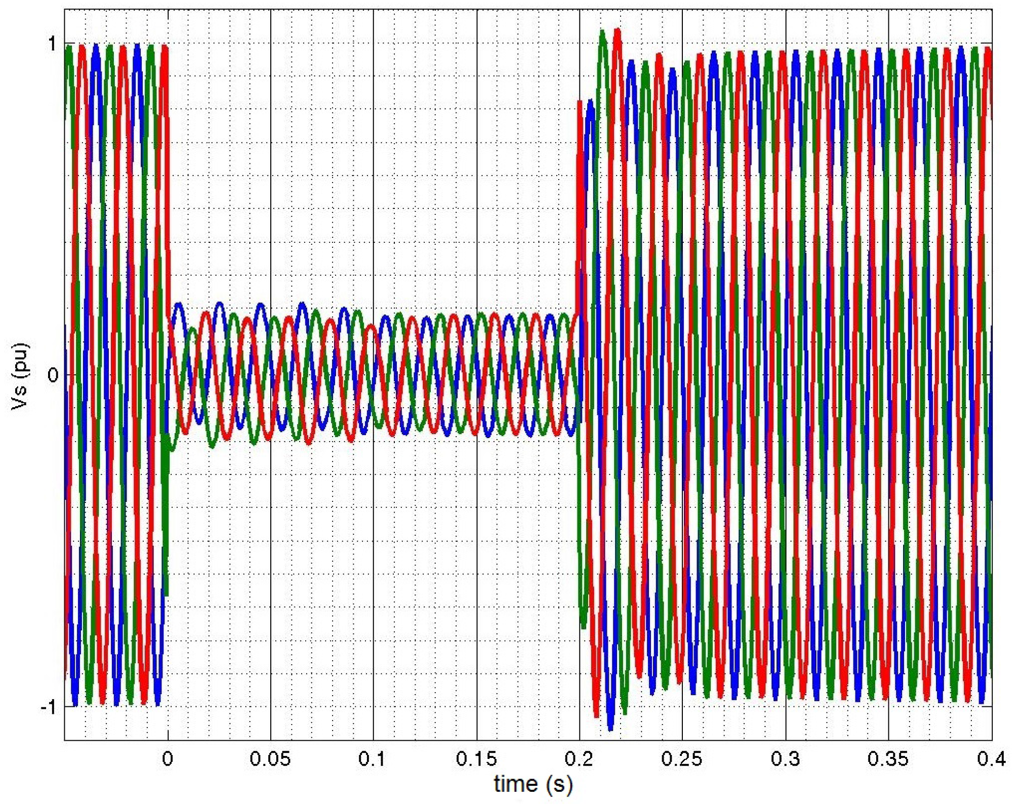
Figure 7 shows the grid voltage during a symmetric voltage sag, with depth equal to
an 0.2 s duration, according to the IEC standards.
Figure 7.
Applied voltage sag.
Figure 7.
Applied voltage sag.
Whenever a voltage dip occurs and rotor currents rise above safe limits, the SCL transits to a normal state inserting a resistance in the circuit. Meanwhile, as rotor currents are continuously measured, the controller is alerted about the voltage dip, disabling the RSC switches while rotor current is higher than 1.2 pu. The RSC works as a diode rectifier. The switches of the RSC remain disabled for a few milliseconds.
Although the superconductor limits the rotor current, a large amount of energy flows to the DC-link of the back-to-back converter. In order to avoid the DC-link voltage to achieve high values, the chopper is activated whenever the DC voltage rises above a safe threshold, and is deactivated below a safety value. The approaches of using the DC chopper along with another control strategy have been proposed recently [
34,
35,
36]. In the simulations, the chopper is turned on at +5% and turned off at +2.5% of DC voltage variation.
6.1. DFIG with SCL between Rotor and RSC
The SCL is positioned between the RSC and the rotor of the DFIG. The critical current () is 1.2 pu and the device resistance () is 2.0 Ω.
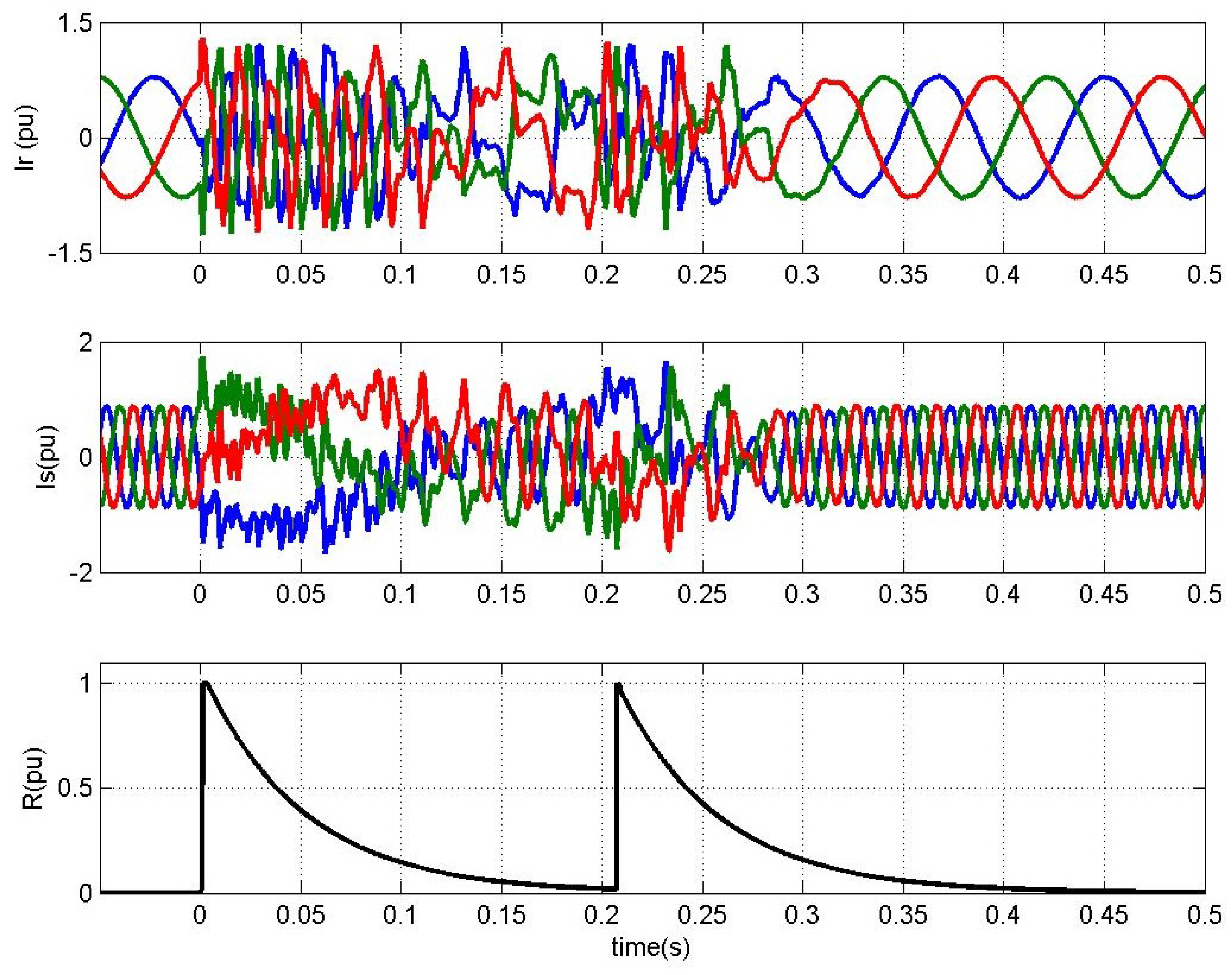
Figure 8 shows DFIG currents and SCL resistance (
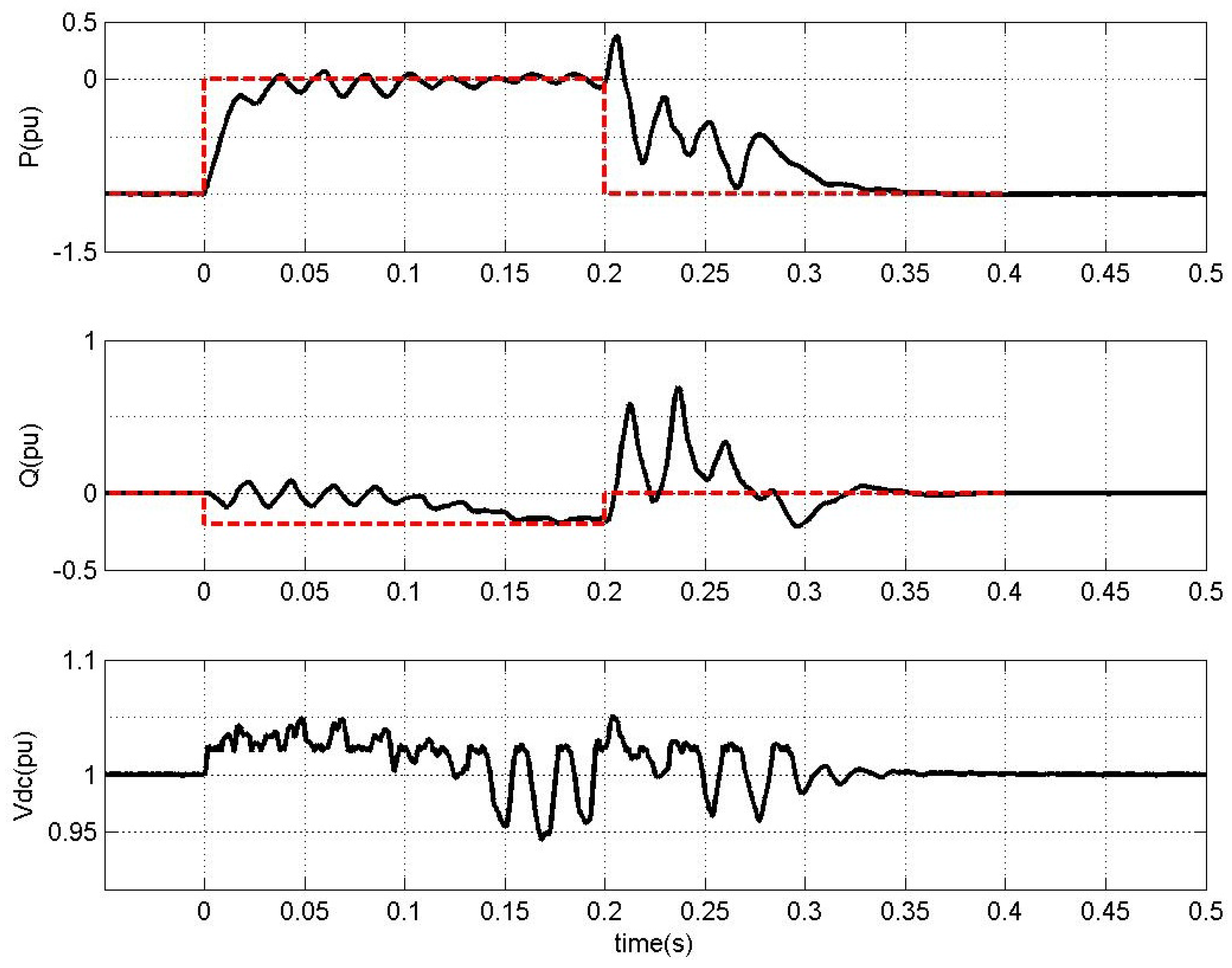
R) behavior. The maximum rotor and stator currents are 1.3 pu and 1.78 pu, respectively. The system has a transient time of 100 ms, as shown in the active and reactive power (PQ) curves of
Figure 9, and DC-link voltage variation is up to 6.5%.
Figure 8.
Rotor and stator current, SCL between rotor and RSC.
Figure 8.
Rotor and stator current, SCL between rotor and RSC.
Figure 9.
Active and reactive power, and DC-link voltage, SCL between rotor and RSC.
Figure 9.
Active and reactive power, and DC-link voltage, SCL between rotor and RSC.
6.2. DFIG with SCL into DC-Link
The SCL has been relocated to the DC-link in order to reduce from three to one the elements required in a three-phase configuration. The relation between similar AC and DC SCL is shown in Equation (19).
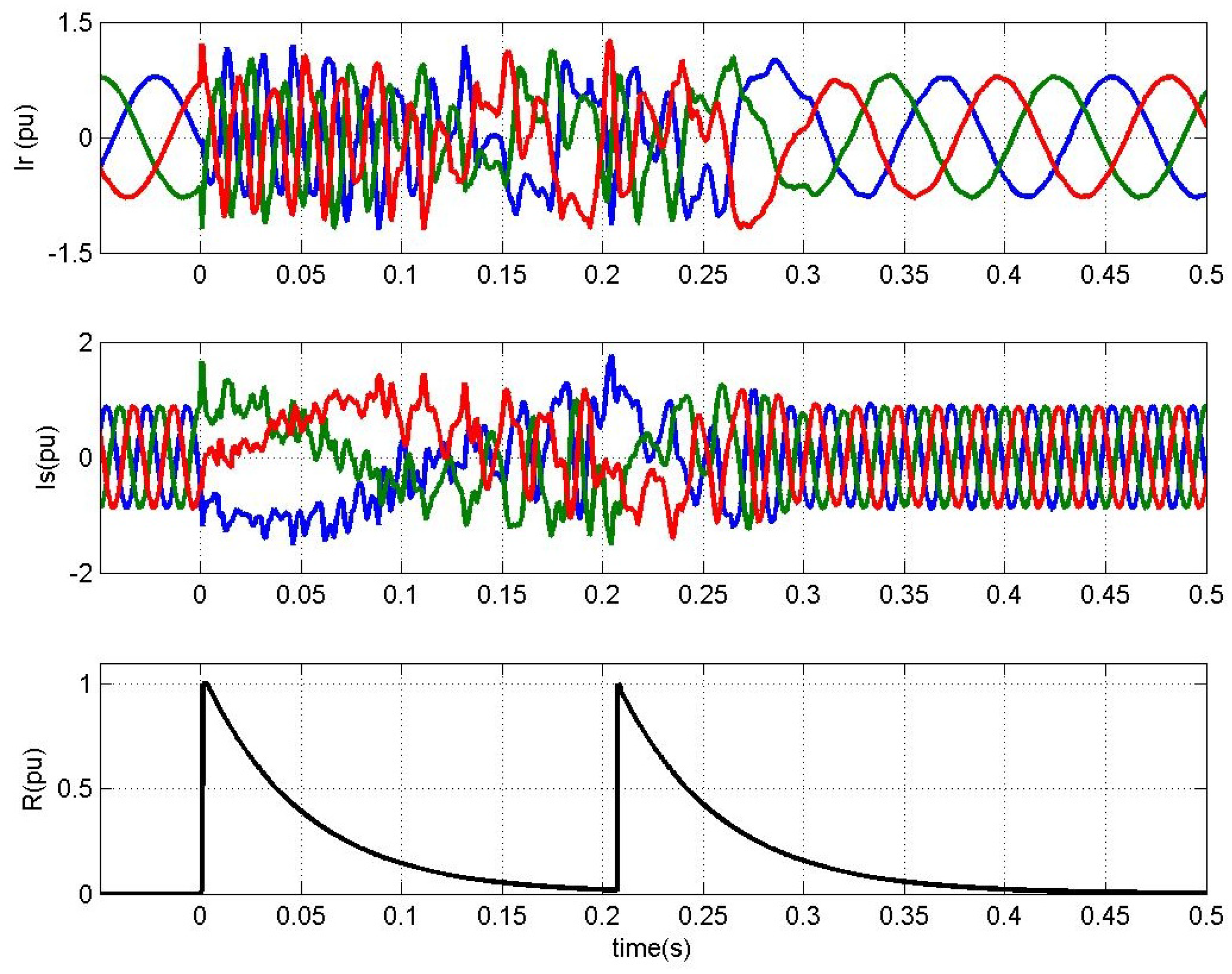
Figure 10 shows DFIG currents with DC SCL and SCL resistance (
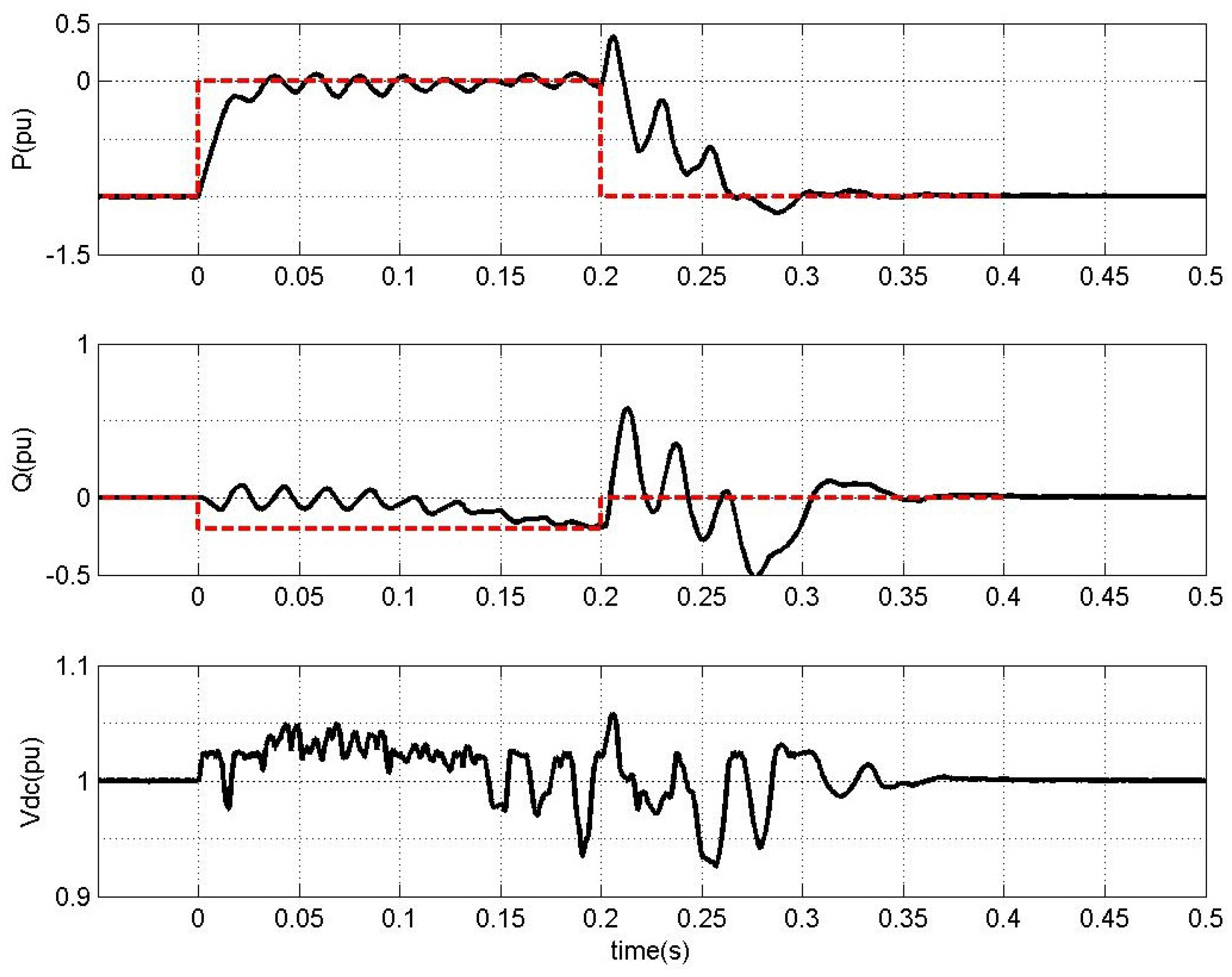
R) behavior. The maximum rotor and stator currents are 1.3 pu and 1.78 pu, respectively. The system has a transient time of 120 ms, as shown in PQ curves of
Figure 11, and DC-link voltage variation is up to 6.5%.
Figure 10.
Rotor and stator currents, SCL into DC-link.
Figure 10.
Rotor and stator currents, SCL into DC-link.
Figure 11.
Active and reactive power, and DC-link voltage, SCL into DC-link.
Figure 11.
Active and reactive power, and DC-link voltage, SCL into DC-link.
7. Conclusions
This paper has studied the dynamic of a 2.0 MW DFIG during a severe voltage sag. Using the dynamic model of a DFIG, it was possible to determine the current, Electromagnetic Force and flux behavior during three-phase symmetrical voltage dip. Two solutions employing superconducting materials were proposed and compared for increasing the robustness of DFIG during balanced voltage dips.
The first solution, connecting the SCL between rotor and RSC and disabling all RSC switches, leaves the DC-link connected in the rotor circuit opposing to current circulation. The rotor current was limited in 1.3 pu and the DC-link voltage variation was smaller than 6.5%. The aforementioned current could achieve a value of 3.2 pu without the SCL. The second solution reduces the three elements required, in a three-phase configuration, by one equivalent element. Both solutions present very similar behavior but the DC-link SCL approach uses a reduced structure. However, if on one hand, the DC-link SCL approach makes use of a reduced structure, on the other hand it leads to high voltages at RSC switches, a damaging solution from the switches point of view.
The main advantages of proposed solutions using SCL in the rotor circuit compared with other technologies employed on DFIG LVRT improvement are pointed out:
The SCL has no influence on the power generation of the DFIG during normal operation;
Higher rotor current limitation during critical period of voltage dip is achieved;
The SCL effect automatically appears in the rotor circuit faster than other solutions;
The device recovers itself to the superconducting state without any external command.
The proposed approaches are effective if using the DC chopper to limit the DC link voltage while the SCL limits the rotor currents. The chopper is not necessary if using a larger DC-link capacitor (ten times or more), but currently it is unfeasible due to economic reasons.
These results demonstrate that the three-phase SCL solution is a feasible alternative of LVRT strategy to DFIG protection.
Acknowledgments
This work is being supported by Research Support Foundation of Espírito Santo-FAPES/National Council for Scientific and Technological Development-CNPq (Support Program for Centers of Excellence - PRONEX 48508675/2009), and Federal University of Espírito Santo-UFES.
Author Contributions
The authors have the same contributions to the paper.
Conflicts of Interest
The authors declare no conflict of interest.
References
- Blaabjerg, F.; Ma, K. Future on power electronics for wind turbine systems. IEEE J. Emerg. Sel. Top. Power Electron. 2013, 1, 139–152. [Google Scholar] [CrossRef]
- Zheng, Z.; Yang, G.; Geng, H. Coordinated control of a doubly-fed induction generator-based wind farm and a static synchronous compensator for low voltage ride-through grid code compliance during asymmetrical grid faults. Energies 2013, 6, 4660–4681. [Google Scholar] [CrossRef]
- Mendes, V.; de Sousa, C.; Silva, S.; Cezar-Rabelo, B.; Hofmann, W. Modeling and ride-through control of doubly fed induction generators during symmetrical voltage sags. IEEE Trans. Energy Convers. 2011, 26, 1161–1171. [Google Scholar] [CrossRef]
- Wu, Z.; Zhu, C.; Hu, M. Improved control strategy for DFIG wind turbines for low voltage ride through. Energies 2013, 6, 1181–1197. [Google Scholar] [CrossRef]
- Erlich, I.; Bachmann, U. Grid code requirements concerning connection and operation of wind turbines in Germany. In Proceedings of the IEEE Power Engineering Society General Meeting, San Francisco, CA, USA, 12–16 June 2005; Volume 2, pp. 1253–1257.
- Lopez, J.; Gubia, E.; Olea, E.; Ruiz, J.; Marroyo, L. Ride through of wind turbines tith doubly fed induction generator tnder symmetrical voltage dips. IEEE Trans. Ind. Electron. 2009, 56, 4246–4254. [Google Scholar] [CrossRef]
- Xiao, F.; Zhang, Z.; Yin, X. Fault current characteristics of the DFIG under asymmetrical fault conditions. Energies 2015, 8, 10971–10992. [Google Scholar] [CrossRef]
- Yan, Y.; Wang, M.; Song, Z.F.; Xia, C.L. Proportional-resonant control of doubly-fed induction generator wind turbines for low-voltage ride-through enhancement. Energies 2012, 5, 4758–4778. [Google Scholar] [CrossRef]
- Arribas, J.R.; Rodríguez, A.F.; Muñoz, A.H.; Nicolás, C.V. Low voltage ride-through in DFIG wind generators by controlling the rotor current without crowbars. Energies 2014, 7, 498–519. [Google Scholar] [CrossRef]
- Morren, J.; de Haan, S.W. Ridethrough of wind turbines with doubly-fed induction generator during a voltage dip. IEEE Trans. Energy Convers. 2005, 20, 435–441. [Google Scholar] [CrossRef]
- Meegahapola, L.; Littler, T.; Flynn, D. Decoupled-DFIG fault ride-through strategy for enhanced stability performance during grid faults. IEEE Trans. Sustain. Energy 2010, 1, 152–162. [Google Scholar] [CrossRef]
- Elshiekh, M.; Mansour, D.; Azmy, A. Improving fault ride-through capability of DFIG-Based wind turbine using superconducting fault current limiter. IEEE Trans. Appl. Supercond. 2013, 23, 5601204. [Google Scholar] [CrossRef]
- Chen, L.; Zheng, F.; Deng, C.; Li, Z.; Guo, F. Fault ride-through capability improvement of DFIG-based wind turbine by employing a voltage-compensation-type active SFCL. Can. J. Electr. Comput. Eng. 2015, 38, 132–142. [Google Scholar] [CrossRef]
- International Electrotechnical Commission. Wind Turbines—Part 21: Measurement and Assessment of Power Quality Characteristics of Grid Connected Wind Turbines; IEC 61400-21; International Electrotechnical Commission (IEC): Geneva, Switzerland, 2008. [Google Scholar]
- Patel, D.; Nagera, A.; Joshi, D. Power quality improvement with static compensator on grid integration of wind energy system. In Proceedings of the 2011 Nirma University International Conference on Engineering (NUiCONE), Ahmedabad, India, 8–10 December 2011; pp. 1–6.
- Sunil, T.; Loganathan, N. Power quality improvement of a grid-connected wind energy conversion system with harmonics reduction using FACTS device. In Proceedings of the International Conference on Advances in Engineering, Science and Management (ICAESM), Nagapattinam, India, 30–31 March 2012; pp. 415–420.
- Hu, J.; He, Y. Modeling and enhanced control of DFIG under unbalanced grid voltage conditions. Electr. Power Syst. Res. 2009, 79, 273–281. [Google Scholar] [CrossRef]
- Mohseni, M.; Masoum, M.A.; Islam, S.M. Low and high voltage ride-through of DFIG wind turbines using hybrid current controlled converters. Electr. Power Syst. Res. 2011, 81, 1456–1465. [Google Scholar] [CrossRef]
- Nian, H.; Quan, Y.; Hu, J. Improved control strategy of DFIG-based wind power generation systems connected to a harmonically polluted network. Electr. Power Syst. Res. 2012, 86, 84–97. [Google Scholar] [CrossRef]
- Abad, G.; Lopez, J.; Rodríguez, M.; Marroyo, L.; Iwanski, G. Doubly Fed Induction Machine: Modeling and Control for wInd Energy Generation; John Wiley & Sons: Hoboken, NJ, USA, 2011; Volume 85. [Google Scholar]
- Oliveira, F.; Passos, C.; Fardin, J.; Simonetti, D.; Passamai, J.; Belich, H.; de Medeiros, E.; Orlando, M.; Ferreira, M. The influence of oxygen partial pressure on growth of the (Hg,Re)-1223 intergrain junction. IEEE Trans. Appl. Supercond. 2006, 16, 15–20. [Google Scholar] [CrossRef]
- Baldan, C.; Lamas, J.; Bernardes, A.; Shigue, C.; Ruppert-Filho, E. Prototype Fault Current Limiter Using Transformer and a Modular Device of YBCO Coated Conductor. J. Superconduct. Nov. Magn. 2013, 26, 1241–1245. [Google Scholar] [CrossRef]
- Nexans-AMSC. Superconductor Fault Current Limiters for MV AC Networks. Available online: http://www.amsc.com/documents/superconductor-fault-current-limiters-for-mv-ac-networks/ (accessed on 3 August 2015).
- Dommerque, R.; Krämer, S.; Hobl, A.; Böhm, R.; Bludau, M.; Bock, J.; Klaus, D.; Piereder, H.; Wilson, A.; Krüger, T.; et al. First commercial medium voltage superconducting fault-current limiters: Production, test and installation. Supercond. Sci. Technol. 2010, 23, 034020. [Google Scholar] [CrossRef]
- Xin, Y.; Gong, W.; Niu, X.; Gao, Y.; Guo, Q.; Xiao, L.; Cao, Z.; Hong, H.; Wu, A.; Li, Z.; et al. Manufacturing and test of a 35 kV/90 MVA saturated iron-core type superconductive fault current limiter for live-grid operation. IEEE Trans. Appl. Supercond. 2009, 19, 1934–1937. [Google Scholar] [CrossRef]
- Silva, F.; Baldan, C.; Fardin, J.; Simonetti, D. Starting current limitation method using HTS for induction motors. J. Supercond. Nov. Magn. 2015, 28, 697–700. [Google Scholar] [CrossRef]
- Nam, K.; Lee, C.; Park, D.K.; Ko, T.K.; Seok, B.Y. Thermal and electrical analysis of coated conductor under AC over-current. IEEE Trans. Appl. Supercond. 2007, 17, 1923–1926. [Google Scholar]
- Falorio, I.; Young, E.; Yang, Y. EJ characteristic of 2G YBCO coated conductor tapes at different temperatures. Phys. Proced. 2012, 36, 1462–1467. [Google Scholar] [CrossRef]
- Ngamroo, I.; Karaipoom, T. Cooperative control of SFCL and SMES for enhancing fault ride through capability and smoothing power fluctuation of DFIG wind farm. IEEE Trans. Appl. Supercond. 2014, 24, 1–4. [Google Scholar] [CrossRef]
- Park, W.J.; Sung, B.C.; Park, J.W. The Effect of SFCL on Electric Power Grid with Wind-Turbine Generation System. IEEE Trans. Appl. Supercond. 2010, 20, 1177–1181. [Google Scholar] [CrossRef]
- Hongesombut, K.; Mitani, Y.; Tsuji, K. Optimal location assignment and design of superconducting fault current limiters applied to loop power systems. IEEE Trans. Appl. Supercond. 2003, 13, 1828–1831. [Google Scholar] [CrossRef]
- Fault Current Limiter Committee. Technical Report of the IEE of Japan; Technical Report 709; Fault Current Limiter Committee: Yokohama, Japan, 1999. [Google Scholar]
- Zhang, W.; Zhou, P.; He, Y. Analysis of the by-pass resistance of an active crowbar for doubly-fed induction generator based wind turbines under grid faults. In Proceedings of the International Conference on Electrical Machines and Systems (ICEMS 2008), Wuhan, China, 17–20 October 2008; pp. 2316–2321.
- Okedu, K.; Muyeen, S.; Takahashi, R.; Tamura, J. Wind farms fault ride through using DFIG tith new protection scheme. Energy IEEE Trans. Sustain. 2012, 3, 242–254. [Google Scholar] [CrossRef]
- Pannell, G.; Zahawi, B.; Atkinson, D.; Missailidis, P. Evaluation of the performance of a DC-link brake chopper as a DFIG low-voltage fault-ride-through device. IEEE Trans. Energy Convers. 2013, 28, 535–542. [Google Scholar] [CrossRef]
- Erlich, I.; Wilch, M.; Feltes, C. Reactive power generation by DFIG based wind farms with AC grid connection. In Proceedings of the 2007 European Conference on Power Electronics and Applications, Lausanne, Switzerland, 1–5 July 2007; pp. 1–10.
© 2015 by the authors; licensee MDPI, Basel, Switzerland. This article is an open access article distributed under the terms and conditions of the Creative Commons by Attribution (CC-BY) license (http://creativecommons.org/licenses/by/4.0/).


 ,
, 
