Article

A New Fast Peak Current Controller for Transient Voltage Faults for Power Converters †

by
Jesús Muñoz-Cruzado-Alba
1,*,
Javier Villegas-Núñez
1,‡,
José Alberto Vite-Frías
1,‡ and
Juan Manuel Carrasco Solís
2,‡
1
R & D Department, GPTech, Av. Camas N26, Bollullos de la Mitacion 41703, Spain
2
Electronics Engineering Department, Seville University, Av. de los Descubrimientos S/N, Seville 41092, Spain
*
Author to whom correspondence should be addressed.
The original paper was presented in A New Fast Peak Current Controller for Transient Voltage Faults for Power Converters. In Proceedings of the EEEIC 2015, Rome, Italy, 10–13 June 2015.
These authors contributed equally to this work.
Energies 2016, 9(1), 1; https://doi.org/10.3390/en9010001
Submission received: 17 September 2015 / Revised: 7 November 2015 / Accepted: 27 November 2015 / Published: 22 December 2015

Abstract

:
Power converters are the basic unit for the transient voltage fault ride through capability for most renewable distributed generators (DGs). When a transient fault happens, the grid voltage will drop suddenly and probably will also suffer a phase-jump event as well. State-of-the-art voltage fault control techniques regulate the current injected during the grid fault. However, the beginning of the fault could be too fast for the inner current control loops of the inverter, and transient over-current would be expected. In order to avoid the excessive peak current of the methods presented in the literature, a new fast peak current control (FPCC) technique is proposed. Controlling the peak current magnitude avoids undesirable disconnection of the distributed generator in a fault state and improves the life expectancy of the converter. Experimental and simulation tests with high power converters provide the detailed behaviour of the method with excellent results.

1. Introduction

Power is typically produced at a wide range of generation plants. Some years ago, for renewable power sources, it was allowed to switch off the source when a voltage fault occurred. Back then, disconnection of that power sources had little, if any, impact on the recovery capability of the electric power grid after a fault. Nowadays, a high penetration of renewable distributed generators (DGs) [1,2,3,4] has toughened the grid connection minimum technical requirements (MTRs) worldwide [5,6,7,8,9,10,11,12,13]. MTRs include voltage sags and phase-jump capability, frequency active power regulation and anti-islanding techniques, among others.
The voltage ride through (VRT) capability requirement has been widely described in recent grid codes [5,6,7,8,9,10,11,12,13]. Table 1 and Table 2 point out some of the most popular MTRs for photo-voltaic (PV) plants about VRT.
First, a maximum allowed voltage profile is defined for voltage excursions. If the fault reaches the error profile, the inverter is allowed to disconnect. German legislation [5] usually is taken as the reference for other legislation. A zero-voltage transient fault is required for 0.15 s. Recent legislation imposes a zero-voltage fault, too, like the Puerto Rican or Jordanian legislation [7,13]. However, other legislation is imposing smaller voltage sag magnitude requirements, but longer in time, for example the Chilean and Romanian grid codes [11,12].
Table 1. Minimum technical requirements (MTRs) review for voltage ride through (VRT) capabilities of photo-voltaic (PV) plants (A). German association of energy and water industries: BDEW; Puerto Rico Electric Power Authority: PREPA; National energy regulator of South Africa: NERSA; Spanish electric grid: REE.
CountryGermanyPuerto Rico
StandardBDEWPREPA
VRT profile Energies 09 00001 i001 Energies 09 00001 i002
Iq VRT Energies 09 00001 i003 Energies 09 00001 i004
Id VRT00
Recovery time5 s5 s
Phase jumpN/DN/D
CountrySouth AfricaSpain
StandardNERSAREE
VRT profile Energies 09 00001 i005 Energies 09 00001 i006
Iq VRT Energies 09 00001 i007 Energies 09 00001 i008
Id VRTPrevious fault Id0
Recovery time5 sN/D
Phase jumpUp to 40°N/D
Table 2. MTRs review for VRT capabilities of PV plants (B). National Commission of Energy: CNE; Electrotechnical Italian Committee: CEI; Electricity Regulatory Commission: ERC; Romanian Electricity Authority: Transelectrica.
CountryChileItaly
StandardCNECEI
VRT profile Energies 09 00001 i009 Energies 09 00001 i010
Iq VRT Energies 09 00001 i011 Energies 09 00001 i012
Id VRTPrevious fault Id0
Recovery timeN/DN/D
Phase jumpN/DN/D
CountryJordanRomania
StandardERCTranselectrica
VRT profile Energies 09 00001 i013 Energies 09 00001 i014
Iq VRT Energies 09 00001 i015 Energies 09 00001 i016
Id VRT00
Recovery time60 s350 ms
Phase jumpN/DN/D
Then, some requirements are imposed over the power generation during the voltage excursions in order to help the system stability. An injection of reactive current (Iq) is always required. Older grid codes, like the Spanish or Italian legislation [8,9], usually require generating the maximum possible capacitive current. However, most recent grid codes usually require a droop relationship between capacity current and the depth of the voltage sag, in order to provide a softener recovery [6,7,12,13].
There are two choices for the active current (Id) requirement: to follow the previous value to the fault state, for example the South African and Chilean cases [6,12]; or to drop the reference to zero, but consumption is not allowed, like the German and Puerto Rican cases [5,7].
A recovery time after the fault requirements could be needed, as well. It could vary from milliseconds [11] to minutes [13].
Finally, most recent grid codes are also including phase-jump fault requirements, for example the South African grid code [6].
The worst scenarios cover the necessity to remain connected against 40° phase-jumps and 0.0 p.u. low voltage excursions, for three-phase and mono-phase faults. A sudden occurrence of this type of fault could cause a peak in the converter output current. Therefore, these current peaks cause unit errors and disconnections, being a hazard to the unit safety.
Together with the operation mode and the imposed limits, response time is crucial in these kinds of events, whose durations are in the order of milliseconds. At the beginning of the fault, any delay could be critical, because the grid voltage could change very fast. Figure 1 shows an uncontrolled peak current due to a severe low voltage excursion in a three-phase power converter.
Figure 1. Peak current fault under a severe low voltage excursion. (a) Transient low voltage profile; (b) stack converter output currents; uncontrolled peak currents marked with green circles.
Energies 09 00001 g001
There is much research on power converter controllers during grid fault conditions [14,15,16,17,18,19], but unfortunately, there is not enough analysis about the uncontrolled beginning of the fault. A new fast peak current control (FPCC) is proposed to help the converter control limiting the over-current peak of the converter at the beginning of the fault. Consequently, hardware and software current protection could be avoided, improving the MTRs compliance. Further, lower peak current reduces insulated gate bipolar transistors (IGBTs)’ degradation and unexpected disconnections from the grid of the power converters, so mean time between failures (MTBF) increases.
This manuscript is organized as follows: Section 2 analyzes in detail the proposed method theory; Section 3 and Section 4 show the test results; discussions are given in Section 5; Finally, the materials and methods used are pointed out in Section 6.

2. Fast Peak Current Control Method

2.1. Power Converter Control Strategy

A two-level three-phase topology has been selected for the study. Industrial high-power grid-tie converters usually use a single-stage inverter topology, with an LC output filter [20,21].
Figure 2 shows a classical DG converter control block scheme. The controller is divided into four layers. The highest level controller generates the appropriate references for the middle controller. The middle level controller reacts by modifying the response as a function of the environment agents, which could limit the inverter capability. Typically, special voltage sag control will be placed at this layer. Then, the low level controller includes the inner current control loop that sets the inverter control actions following the references. Finally, the hardware level controller translates the control signals to the physical pulses of the converter.
Figure 2. Simplified control block scheme of a distributed generator (DG) power converter.
Energies 09 00001 g002
The proposed FPCC will be improved with two individual actions. Gray boxes in Figure 2 show where these actions take place. On the one hand, in the lower level, the duty cycle control signal is saturated with a theoretical current limit, called the fast predictive peak current saturation (FPPCS) method. On the other hand, at the hardware level, the delay of duty control signal updating is reduced without modifying pulse width modulation (PWM) switching frequency with a technique denoted as duty signal updating improvement (DSUI).

2.2. Fast Predictive Peak Current Saturation Method

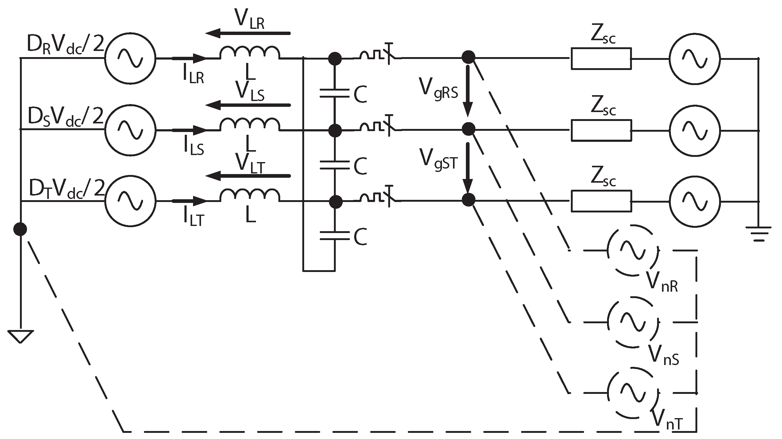
Figure 3 shows a simplified single-line model of the converter as an ideal controlled voltage source. This model has been widely presented in the literature [22]. The converter output line-to-line voltage (VgRS, VgST) is defined by an impedance (Zsc) and a grid voltage source. The measured voltage could be used to build up an equivalent voltage source model (VnR, VnS, VnT) connected to the virtual neutral point of the converter model (noted by the dashed lines in Figure 3).
Equation (1) shows the relationship of the inductor voltage (VL) with the voltage source model of Figure 3 and with the differential equation of an inductor:
V L = D V dc 2 V n L d I L d t
where Vdc is the DC-link voltage, Vn is the grid voltage, D is the DG duty control signal in the range of [−1, 1], L is the inductive value of the filter value and IL is the current across the inductance. Since the controller is executed periodically at a fixed frequency Fs, Equation (1) could be discretized, and D would be given by Equation (2):
D k = 2 L ( I L k + 1 I L k ) F s + V n k V dc k
Figure 3. Simplified inverter voltage source model.
Energies 09 00001 g003
Equation (2) gives the relationship between IL time evolution and the control signal value. Consequently, the current measurement on the next step control could be predicted. Imposing a control law restriction with a maximum current threshold IFPPCS, Equation (3) sets a theoretical maximum control signal:
D max R k = 2 L ( I FPPCS I R k ) F s + V g k V dc k D max S k = 2 L ( I FPPCS I S k ) F s + V g k V dc k D max T k = 2 L ( I FPPCS I T k ) F s + V g k V dc k
where D max R k , D max S k and D max T k are the maximum duty allowed control signals for the defined IFPPCS in each phase and I R k , I S k and I T k are the measured currents of the three phases at the k instant.

2.3. Duty Signal Updating Improvement Method

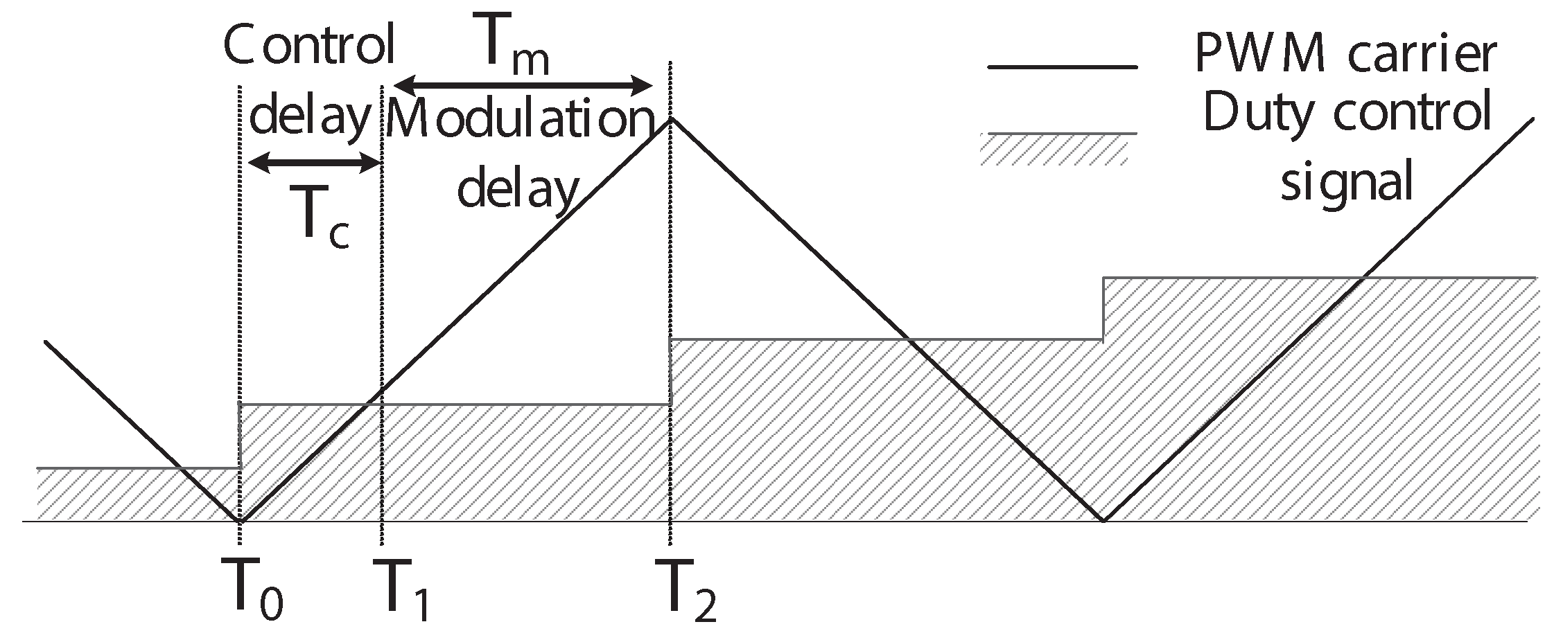
Typically, PWM techniques update only their control signals in the valleys and peaks of the triangular carrier, T0 and T2 respectively (see Figure 4), guaranteeing non-desirable firing, the switching frequency remaining constant and avoiding extra power losses [23].
Figure 4 shows a typical delay added in a power converter controller. If the control processor needs the computational time (Tc) since the last sampling time (T0), then an additional delay of Tm will be inserted before the action will be executed, because the control signal can only be updated in the peaks and the valleys. The proposed technique updates the control signal at T1 with some restrictions. Then, only Tc delay happens, and the peak current under faulty conditions will drop.
Figure 4. Typical delay added in a power converter controller. The measures are taken at T0, but Tc is needed to calculate the next control signal. Finally, the control signal is updated and applied at T2. Pulse width modulation: PWM.
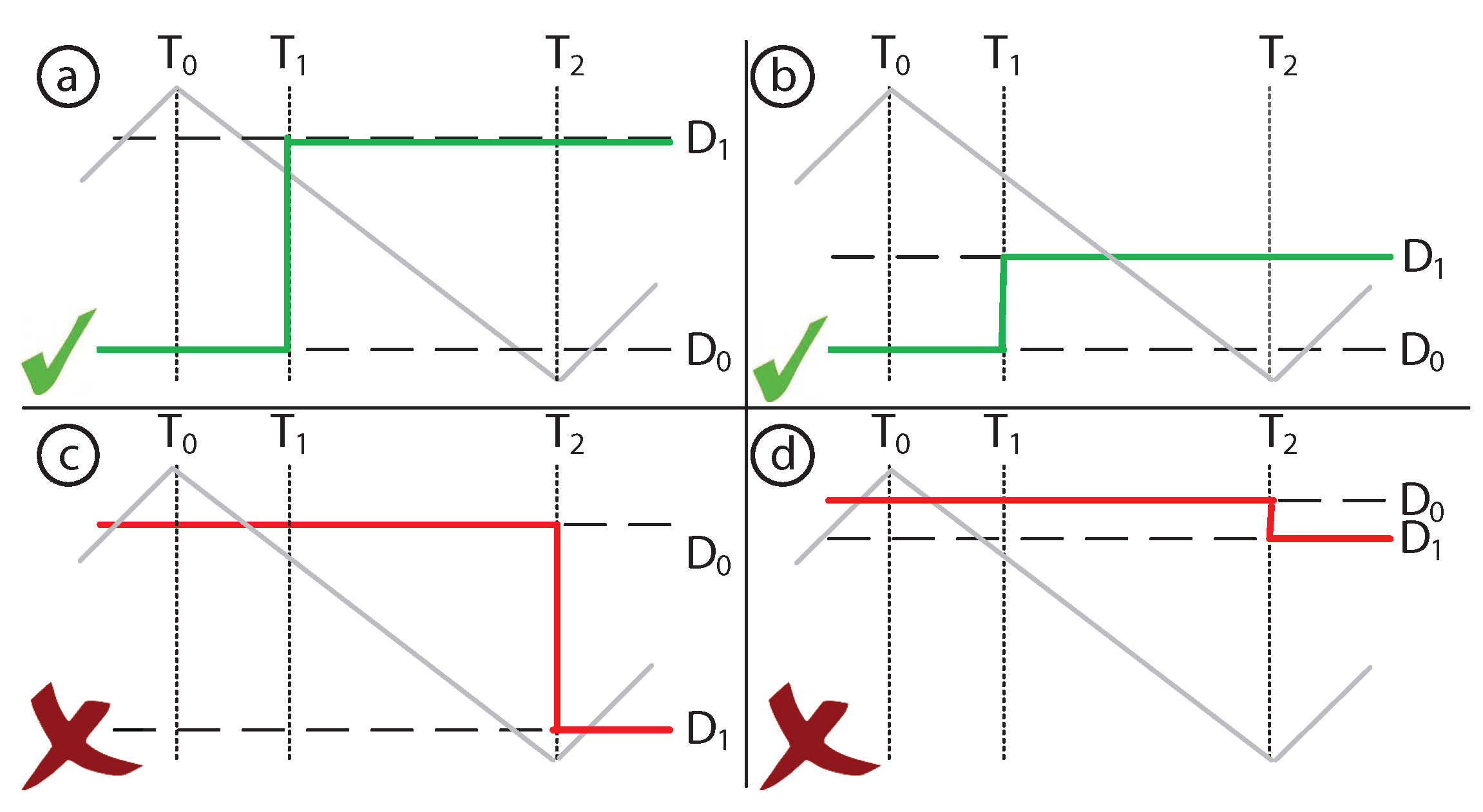
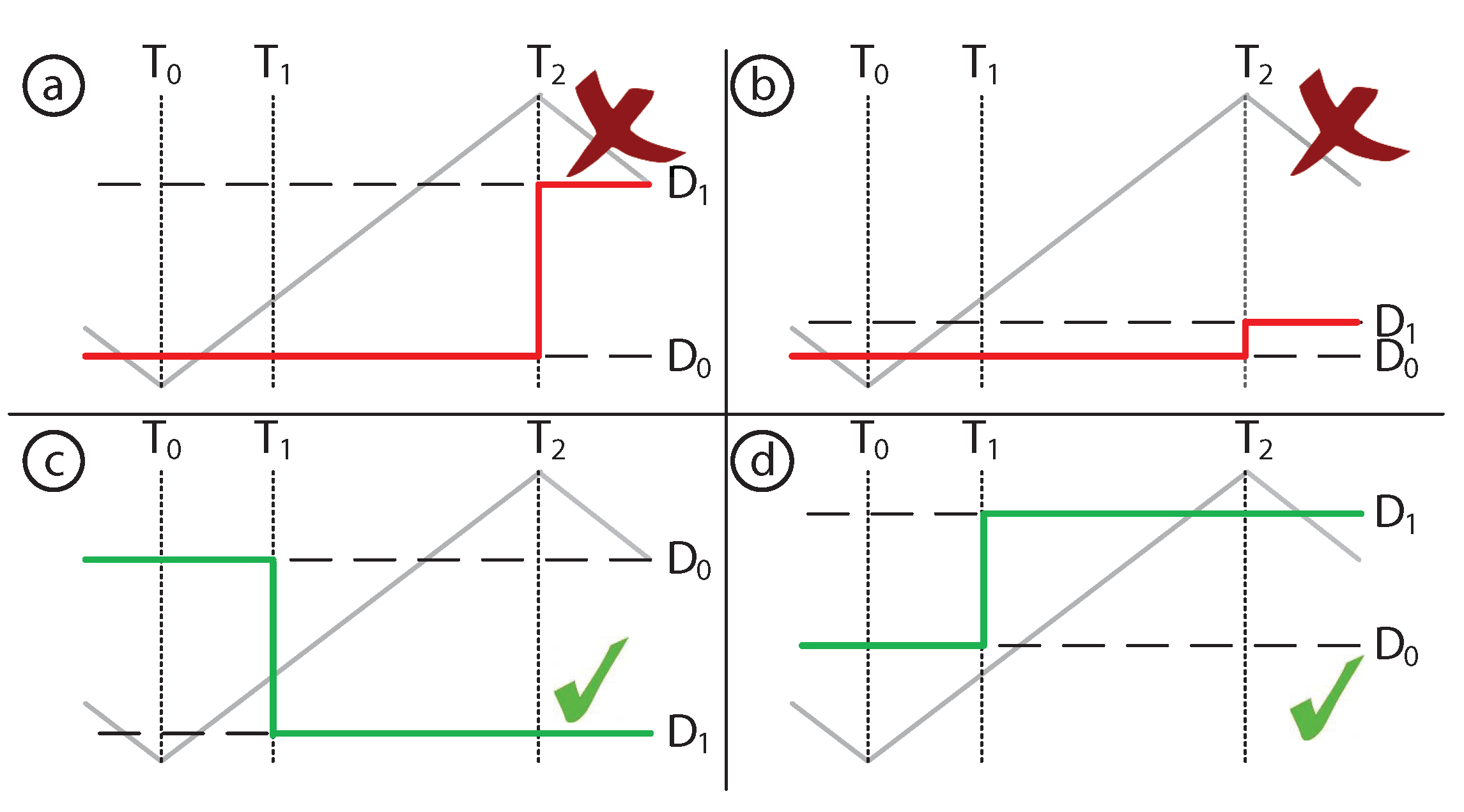
Energies 09 00001 g004
As an example, Figure 5 shows all four possible cases in the up-slope PWM carrier semi-cycle, but similar cases could be exposed in the down-slope semi-cycle. On the one hand, during the up-slope, if the previous control signal (D0) is greater than the triangular carrier value at T1, no extra transition is guaranteed, and the new control signal (D1) could be updated without any additional switching in the semi-cycle (Cases c and d in Figure 5). On the other hand, if D0 is lower than the triangular carrier at T1, at least three transitions may occur if D1 is updated at T1: the first one belongs to the D0 level; a second transition happens at T1; and a third transition will happen at the D1 level. Consequently, the control signal will be updated in the next valley or peak to avoid extra switching (Case a in Figure 5). Finally, Case b does not produce any extra-switching, but neither modifies the control output.
Figure 5. All four possible duty updating cases in the rising PWM semi-cycle. The control signal could be updated at T1 in Cases c and d, but must be updated at T2 in Cases a and b.
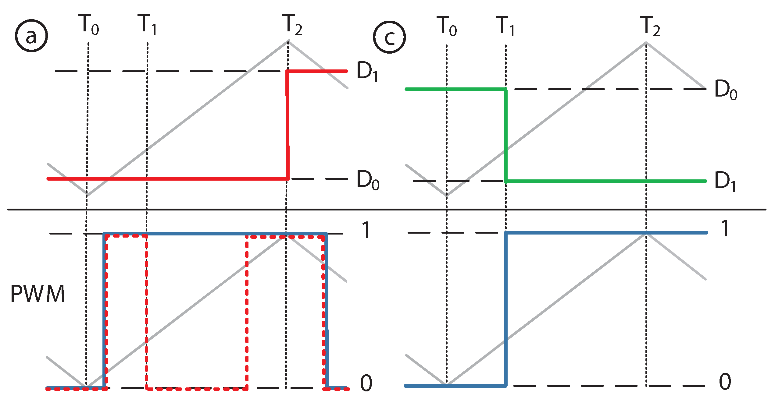
Energies 09 00001 g005
Graphically, Figure 6 shows an example of PWM signals generated in Cases a and c. In Case c, the duty signal is updated (blue line) without producing extra switching, reducing the on state of the semiconductor. However, in Case a, the control signal must be updated in T2 (solid blue line); otherwise, two switching events will happen (dotted red line).
Figure 6. PWM signals generated with Cases a and c of the rising PWM semi-cycle. The red dotted line points out possible malfunctioning with two switchings in the same semi-cycle if the proposed rule is not applied. The blue line points out PWM signals generated with the duty signal updating improvement (DSUI) method.
Energies 09 00001 g006
Following the same steps, along the modulation down-slope cycle, if D0 is lower than the modulation value at T1, the control signal could be updated without any change in the switching frequency. Figure 7 shows all four possible cases on the down-slope semi-cycle.
Figure 7. All four possible duty updating cases in the falling PWM semi-cycle. The control signal could be updated at T1 in Cases a and b, but must be updated at T2 in Cases c and d.
Energies 09 00001 g007
Fortunately, not all cases are relevant with respect to current faults. Therefore, a study could be made to determine the effectiveness of the improvement in these special cases. There are two fault conditions: a positive and a negative over-current peak. From here, the up-slope case will be analyzed, but a similar reasoning could be done for the down-slope semi-cycle.
According to Equation (2), at instant k = 1, the worst over-current peak ( I L 0 ) would happen if the current peak fault was add up over the maximum current value modulated. Consequently, D0 is expected to be positive and big enough. In addition, if a dangerous peak current happened, the controller would have to drop IL to a safety region. According to Equation (2), to take down I L 1 , D1 will be very low. Therefore, if a positive over-current peak happens, Case c of Figure 5 is expected. As previously mentioned, this is one of the allowed cases to refresh the control signal, so the over-current peak will be reduced.
A similar reasoning could be made with a negative over-current fault. On the one hand, now, D0 is expected to be negative and big enough. On the other hand, from Equation (2), the D1 expected value will be very high. Consequently, if a negative over-current peak happens, Case a or d of Figure 5 is expected. If Case d happens, the control signal will be updated, and the over-current peak will be reduced. Unfortunately, if Case a happens, the method will not act in this semi-cycle.
Figure 5 points out that Tc influences the effectiveness of the method. If Tc is forced to zero, all control steps will be in the c and d cases, so it is important to have a small delay Tc to short the measured peak current in most situations.
Finally, one more action could be performed to reduce the over-current peak. A fault happening in semi-cycle k will be measured at the beginning of the next semi-cycle k + 1, and the control action will be placed at T1 in the best case or at the beginning of k + 2 in the worst case. Therefore, the maximum delay could be 2Ts or Ts + Tc.
If Tc is relatively short, a new control step could be done at the middle of the semi-cycle. This control signal will be applied with the same rules as the others, so in a general way, it will be placed at the final part of the semi-cycle. In this case, if a fault happens at the middle of the semi-cycle k′, it will be measured at the beginning of the next control step k′ + 1, and the control action will be placed at T1 in the best case or at the beginning of k′ + 2 in the worst case. Therefore, the maximum delay could be Ts or 0.5 · Ts + Tc. Assuming VL constant in a short period of time during the fault condition:
I L = 1 L V L d t Δ I L = V L L · T delay
where ΔIL is the expected increment on the peak current induced by the fault and Tdelay is the time necessary to control the fault. Therefore, according to Equation (4), the peak current will be reduced in:
P I max = V L L · 1.5 T s V L L · 2 T s = 0.75 p.u. P I min = lim T c 0 V L L · ( 0.5 T s + T c ) V L L · T s + T c = 0.5 p.u.
where PI is the proportion of the peak current reduced with the improvement (between 50% and 75%).

3. Simulations

A high power industrial PV solar inverter has been modeled to test FPCC. However, similar results could be obtained with other applications. The following devices have been modeled in the simulation: a solar panel field; a detailed commercial model of a two-level three-phase power inverter; a medium voltage transformer; the point of interconnection (POI) with the utility grid; a RL divider to generate voltage sags and phase-jumps.
Two types of faults have been analyzed at full power. The worst cases described in the international legislation [5,6,7,8,9,10,11,12,13] have been selected. The system will be tested against symmetric and asymmetric voltage sags and phase-jump faults. Figure 8 shows line-to-line voltages of the deepest faults of each type used to test the system. Case a shows a three-phase voltage fault with zero remaining voltage. Case b shows an asymmetric voltage fault with two phases overlapped. Case c shows a three-phase 45° voltage phase-jump. Finally, Case d shows the same phase-jump for only one phase.
Figure 8. Line-to-line three-phase grid voltage for all types of faults tested. (a) Three-phase zero-voltage fault; (b) asymmetric zero-voltage fault; (c) three-phase 45° voltage phase-jump and (d) mono-phase 45° voltage phase-jump.
Energies 09 00001 g008
Figure 9 and Figure 10 show the transient power converter response against a 45° three-phase jump disturbance and a 0.0 p.u. three-phase dip voltage, respectively, fired at 0.00 s. For both figures, (a) shows the transient behavior of one phase voltage (Vg). Figure 9b shows the phase (θ) transient to 45° and Figure 10b the voltage module (m) transient to 0.0 p.u., during the fault. Cases c to e show two curves fir each one; the solid line curve represents the evolution of the system with a classical approach (CA), and the dashed line curve represents the evolution of the system with FPCC. Cases c to e show the duty signal control (D), the stack output current (IL) and the converter output current (Iout), respectively. Note that software protection (SP) and hardware protection (HP) thresholds are pointed out over Case d and how, with the FPCC active, the threshold is not reached. As a result, the unit remains connected. The Iout peak is reduced, too, but additional remaining peaks appear in the converter output due to the line capacitor filter.
Figure 9. DG response against a 45° phase-jump fault with the classical approach (CA) and FPCC techniques. (a) Grid voltage; (b) phase; (c) duty control signal; (d) stack current and (e) converter current output.
Energies 09 00001 g009
Figure 10. DG response against a 0.00 p.u. three-phase dip voltage with the classical approach (CA) and fast peak current (FPCC) techniques. (a) Grid voltage; (b) module; (c) duty control signal; (d) stack current and (e) converter current output.
Energies 09 00001 g010
However, results may differ depending the triggering time of the fault. To cope with this effect, all cases have been repeated ten times, firing the fault at different instants to look for the worst case. Table 3 shows a comparison of several phase-jumps and voltage sags. Several values have been tested for both the mono-phase and the three-phase cases. In every cell, values at the left are for IL, and values at the right are for Iout. In order to quantize the weight of each improvement in the overall result, three cases are considered in the study: the classical approach (CA) method, only the FPPCS algorithm and the complete FPCC technique.
Table 3. Simulations results against dip voltage and phase-jump faults. FPPCS, fast predictive peak current saturation.
FaultPhasesValueMax. IL-Iout p.u.
p.u.CAFPPCSFPCC
Phase-jump3101.34–1.671.29–1.541.18–1.51
Phase-jump3201.42–1.831.36–1.601.21–1.60
Phase-jump3301.49–1.931.39–1.651.23–1.64
Phase-jump3401.56–2.021.41–1.691.25–1.66
Phase-jump3451.59–2.041.42–1.731.26–1.67
Phase-jump1101.32–1.651.27–1.471.18–1.46
Phase-jump1201.44–1.811.35–1.551.20–1.55
Phase-jump1301.50–1.921.38–1.601.22–1.59
Phase-jump1401.60–1.991.40–1.651.24–1.61
Phase-jump1451.62–2.011.40–1.681.24–1.62
Dip voltage30.21.51–1.791.32–1.561.18–1.53
Dip voltage30.11.65–2.001.38–1.651.22–1.62
Dip voltage30.01.83–2.261.45–1.831.28–1.79
Dip voltage10.21.47–1.751.30–1.541.18–1.48
Dip voltage10.11.61–1.951.36–1.641.21–1.61>
Dip voltage10.01.77–2.201.42–1.811.26–1.78
Table 3 shows FPCC over-currents about 0.4 p.u. lower than the CA method and helps to maintain the range of operation of the converter (SP at 1.3 p.u.). The table also shows results for the influence of every part of the method.

4. Experimental Validation

FPCC results had been verified experimentally. A real high power test bench has been used with a three-phase two-level grid-tied inverter DG for PV applications.
The same voltage sags and phase-jumps of simulation tests have been selected, in accordance with the fault descriptions of the main international legislation [5,6,7,8,9,10,11,12,13]. All tests have been repeated five times to ensure results with different triggering conditions, and the tests were performed with CA, only FPPCS and FPCC complete improvement to compare the results.
Repeating simulation tests, Figure 11 and Figure 12 show the transient power converter response against a 45° three-phase jump disturbance and a 0.00 p.u. three-phase dip voltage, respectively, fired at 0.00 s. For both figures, Curve a shows the transient behavior of Vg. Cases b and c show IL with CA and FPCC, respectively. Finally, Cases d and e show Iout with CA and FPCC, respectively. The SP threshold is not reached in the case of FPCC active, verifying the simulation results.
Finally, all tests have been repeated ten times, and the worst results are shown in Table 4. Three cases are considered in the study: CA, only FPPCS and FPCC complete methods. Again, the simulation results are validated, and the experimental peak current working under faulty conditions is greatly reduced with FPCC.
Figure 11. DG response against a 45° phase-jump fault with the CA and FPCC techniques. (a) Grid voltage; (b,c) stack current and (d,e) converter current output.
Energies 09 00001 g011
Figure 12. DG response against a 0.00 p.u. three-phase dip voltage with CA and FPCC techniques. (a) Grid voltage; (b,c) stack current and (d,e) converter current output.
Energies 09 00001 g012
Table 4. Experimental results against dip voltage and phase-jump faults.
FaultPhasesValueMax. IL P.u.
p.u.CAFPPCSFPCC
Phase-jump3101.151.151.12
Phase-jump3201.211.181.12
Phase-jump3301.591.171.15
Phase-jump3401.691.251.17
Phase-jump3451.731.241.24
Phase-jump1451.261.161.16
Dip voltage30.21.651.271.14
Dip voltage30.11.741.341.16
Dip voltage30.01.871.521.21
Dip voltage10.01.461.261.17

Model Validation

Finally, a transient comparison between simulations and experimental results could be very meaningful in order to validate the model. Two cases are considered, both for a three-phase zero-voltage remaining fault; one case under a classic control approach and the second with the proposed FPCC method.
Figure 13 shows the voltage and stack current outputs for a 0.00 p.u. three-phase dip voltage with the CA technique. Cases a and b show line-to-line voltage and how the voltage is generated at the same instant and with the same behavior for simulations and experiments, respectively. Additionally, Cases c and d show the stack output currents for the three phases. Results show approximately the same magnitudes in simulations and experiments.
Figure 13. Simulation and experiment response against a 0.00 p.u. three-phase dip voltage with the CA technique. (a) Simulation line-to-line three-phase grid voltage; (b) experiment line-to-line grid voltage; (c) simulation stack current outputs and (d) experiment stack current outputs.
Energies 09 00001 g013
Moreover, Figure 14 shows the voltage and stack current outputs for a 0.00 p.u. three-phase dip voltage with the FPCC technique. The same four cases are presented (grid voltage and output stack currents in simulation and experimental tests). Again, the same behavior is proven for simulations and real experiments, observing the same slopes and peak current magnitudes.
In conclusion, Figure 13 and Figure 14 prove that the simulation test model has a very accurate response compared to real experiments. Therefore, the simulation test results presented are validated.
Figure 14. Simulation and experiment response against a 0.00 p.u. three-phase dip voltage with the FPCC technique. (a) Simulation line-to-line three-phase grid voltage; (b) experiment line-to-line RS grid voltage; (c) simulation stack current outputs and (d) experiment stack current outputs.
Energies 09 00001 g014

5. Discussion

The proposed FPCC highly reduces the peak currents detected by the converters of DGs. The method theory has been analyzed in detail, and results verify the effectiveness of the method via simulation. Furthermore, an experimental validation with an industrial high power solar power converter has been performed with excellent results. The relationship between simulation and experimental results is consistent, so the models used have proven their efficacy.
Peak currents for all types of faults (voltage sags and phase jumps) have been reduced, avoiding critical thresholds. Severe faults cause larger peaks currents than small faults under a classical control technique. However, peak currents do not increase in the same way with the FPCC technique. The increment of peak current magnitudes is flatter with FPCC than with a classical approach. Consequently, the range of tolerance against faults is increased.
Note that the FPCC threshold is set to 1.05 p.u. for all tests. Results show peak currents between 1.12 p.u. and 1.24 p.u. Therefore, the control threshold has been passed only 0.07–0.17 p.u. Therefore, the efficiency of the method has been measured.
The output current of the converter is greater than the stack output current significantly. This is due to the energy saved in the AC capacitors of the output filter of the converter. The peak current component due to AC capacitors is not reduced with FPCC, because it is not controlled by the converter. Therefor, the output current of the converter is greater than the stack current output. However, the most critical components against peak currents are IGBTs, so the extra current added by the capacitors does not increase the risk of failure.
Finally, the main advantages of FPCC are summarized in the next sentences:
  • The peak current has been reduced between 0.4 p.u. and 0.7 p.u. for the worst cases.
  • The method helps to comply with international MTRs.
  • The method prevents the unit from tripping by over-current, reducing production losses and helping the grid recover from the fault.
  • Reducing peak currents prevents unit damage. Consequently, the MTBF of the units is longer.
  • The method does not need any additional hardware, so it is very inexpensive and easy to implement in existing units.

6. Experimental Section

6.1. Simulations

A high power industrial PV solar inverter has been modeled to test FPCC. Simulations had been performed with the electric transient power tool EMTDC/PSCAD V4.2.
Figure 15 shows a detailed description of the simulation. The simulation includes:
  • Solar panel field model.
  • Detailed commercial two-level three-phase grid-tie inverter; the inverter acts as the device under test (DUT) of the simulation.
  • Medium voltage transformer.
  • POI with the utility grid.
  • Variable parallel impedance load to perform voltage sags and phase-jumps.
Figure 15. Detailed simulation scheme to test FPCC.
Energies 09 00001 g015
The PV panels have been modeled according to the diode model [24]. The main parameters used to configure the panel are summarized in Table 5. Test conditions have been set to reach maximum power.
Table 5. PV panel model setup.
Panel Nominal ValuesValueTest ConditionsValue
Active power (PMPP;STC)500 kWTemperature (T)25 °C
Voltage (UMPP;STC)825 VIrradiance (G)1000 Wm2
Temperature (TSTC)25 °CPanel technologyValue
Irradiance (GSTC)1000 Wm2Coefficient of voltage change Ffu0.8 p.u.
Temperature modelValueCoefficient of current change Ffi0.9 p.u.
Temperature correction T00 °CTechnology coefficient Cg2.514 × 10−3 W/m2
Irradiance gain k0.03 m2/WTechnology coefficient Cv0.08593 p.u.
Time constant τ300 sTechnology coefficient Cr1.088 × 10−4 m2/W
Irradiance change Vl2h0.95 p.u.
Current temperature α0.0004 p.u.
Voltage temperature β−0.004
The main parameters of the commercial two-level three-phase grid-tie inverter are summarized in Table 6. Nominal values, inner current control PIDs, switching frequency, software protections and the FPCC setup are detailed.
Table 6. Grid-tied inverter setup.
ParameterValueParameterValue
Nominal active power PDG500 kWOver-current software protection SP1.3p.u./0.1 ms
Nominal output current In1202 AOver-current hardware protection HP1.4 p.u.
Nominal grid voltage Vn240 VActive current controlkpD = 0.05
kiD = 5
FPPCS limit IFPPCS1.05 p.u.Reactive current controlkpQ = 0.05
kiQ = 5
Delay control time Tc0.6 p.u.PWM frequency fPWM1980 Hz
The POI is simulated with an ideal three-phase voltage source at VL = 23 kV and f = 60 Hz, with a short circuit power (Ssc) of 500 MVA. Additionally, the medium voltage transformer is detailed in Table 7. Finally, faults are modeled with an RLthree-phase impedance, regulating values to desired faults.
Table 7. Medium voltage transformer setup.
ParameterValueParameterValue
Primary winding voltage23 kVNominal power0.6 MWe
Secondary winding voltage0.24 kVNominal grid frequency60 Hz
Winding typeYΔLeakage reactance0.12 p.u.
Copper losses0.01 p.u.

6.2. Testbench

FPCC results had been verified experimentally with a real high power test bench. Figure 16 shows a diagram (a) and a photo (b) of the test bench used for the experiments.
Figure 16. Test-bench scheme (a) and panoramic view (b); the device under test (DUT) is on the right side of the photo, and the rectifier and generator are in the background. The power transformer is inside the metallic jail.
Energies 09 00001 g016
The utility grid was emulated with an electronic power converter generator in order to perform controlled faults. A three-phase two-level converter was used. A grid of 240 V and 60 Hz was generated to perform all tests.
The DUT selected was a commercial high-power three-phase two-level grid-tied inverter DG for PV applications. The converter was set according to Table 6.
PV panels were emulated with a controlled rectifier that provided a suitable DC voltage input for both the DG and the electronic generator. A three-phase two-level converter was used. The rectifier could provide a DC-link input voltage from 425 V–825 V.
The transformer has a YY configuration, with winding voltages of 400 V:400 V and a short-circuit impedance of 0.09 p.u. Finally, all wiring in the test bench was enough to fulfil the power demands, and no significant inductance was added (three wires of 240 mm in diameter per phase).

Acknowledgments

This work was supported by GPTech Spain (http://www.greenpower.es) and the Electronic Engineering Department of the University of Seville.

Author Contributions

Jesús Muñoz-Cruzado-Alba conceived of and designed the proposed control strategy and significantly contributed to the implementation of the simulation and test bench. Javier Villegas-Núñez and José Alberto Vite-Frías helped in the laboratory tests and the writing of the paper. Juan Manuel Carrasco Solís responsible for guidance and a number of key suggestions.

Conflicts of Interest

The authors declare no conflict of interest.

References

  1. Hashemi, S.; Yang, G.; Ostergaard, J.; You, S.; Cha, S. Storage application in smart grid with high PV and EV penetration. In Proceedings of the 2013 4th IEEE/PES Innovative Smart Grid Technologies Europe (ISGT EUROPE), Lyngby, Denmark, 6–9 October 2013; pp. 1–5.
  2. Ma, T.; Lashway, C.R.; Song, Y.; Mohammed, O. Optimal renewable energy farm and energy storage sizing method for future hybrid power system. In Proceedings of the 2014 17th International Conference on Electrical Machines and Systems (ICEMS), Hangzhou, China, 22–25 October 2014; pp. 2827–2832.
  3. Ziadi, Z. Optimal Power Scheduling for Smart Grids Considering Controllable Loads and High Penetration of Photovoltaic Generation. IEEE Trans. Smart Grid 2014, 5, 2350–2359. [Google Scholar] [CrossRef]
  4. Hejazi, H.A.; Mohsenian-Rad, H. Optimal Operation of Independent Storage Systems in Energy and Reserve Markets With High Wind Penetration. IEEE Trans. Smart Grid 2014, 5, 1949–3053. [Google Scholar]
  5. Guideline for Generating Plants, Connection to and Parallel Operation with the Medium-Voltage Network; German Association of Energy and Water Industries (BDEW): Berlin, Germany, 2008.
  6. Grid Connection Code for Renewable Power Plants (RPPs) Connected to the Electricity Transmission System (TS) or the Distribution System (DS) in South Africa; rev 2.6; National energy regulator of South Africa (NERSA): Pretoria, South Africa, 2012.
  7. Minimum Technical Requirements for Photovoltaic Generation (PV) Projects; Puerto Rico Electric Power Authority (PREPA): San Juan, Puerto Rico, 2012.
  8. Requisitos de Respuesta Frente a Huecos de Tensión de las Instalaciones de Producción de Régimen Especial; Spanish electric grid (REE): Madrid, Spain, 2006. (In Spanish)
  9. Allegato A.70: Regolazione Tecnica dei Requisiti di Sistema Della Generazione Distribuita; Rev. 01; TERNA: Rome, Italy, 2012. (In Italian)
  10. Inverters, Converters, Controllers and Interconnection System Equipment for Use With Distributed Energy Resources; UL Standard 1741, rev02; Underwriters Laboratories Inc (UL): Northbrook, IL, USA, 2010.
  11. Technical Requirements for Connecting Photovoltaic Power Plants to the National Energy System; Transelectrica: Bucarest, Romania, 2013.
  12. Norma Técnica de Seguridad y Calidad de Servicio; Electric national commission (CNE): Santiago de Chile, Chile, 2015. (In Spanish)
  13. Technical Requirements and Evaluation of Grid Code Compliance for Photovoltaic Power Plants Connected to the Medium Voltage Level in Jordan; Electricity Regulatory Commission (ERC): Amman, Jordan, 2014.
  14. Rodriguez, P.; Timbus, A.V.; Teodorescu, R.; Liserre, M.; Blaabjerg, F. Flexible Active Power Control of Distributed Power Generation Systems During Grid Faults. IEEE Trans. Ind. Electron. 2007, 54, 2583–2592. [Google Scholar] [CrossRef]
  15. Castilla, M.; Miret, J.; Camacho, A.; de Vicuna, L.G.; Matas, J. Modeling and Design of Voltage Support Control Schemes for Three-Phase Inverters Operating Under Unbalanced Grid Conditions. IEEE Trans. Power Electron. 2014, 29, 6139–6150. [Google Scholar] [CrossRef]
  16. Miret, J.; Castilla, M.; Camacho, A.; de Vicuña, L.G.; Matas, J. Control Scheme for Photovoltaic Three-Phase Inverters to Minimize Peak Currents During Unbalanced Grid-Voltage Sags. IEEE Trans. Power Electron. 2012, 27, 4262–4271. [Google Scholar] [CrossRef]
  17. Yaramasu, V.; Wu, B.; Alepuz, S.; Kouro, S. Predictive Control for Low-Voltage Ride-Through Enhancement of Three-Level-Boost and NPC-Converter-Based PMSG Wind Turbine. IEEE Trans. Ind. Electron. 2014, 61, 6832–6843. [Google Scholar] [CrossRef]
  18. Vite, J.A.; Múñoz-Cruzado Alba, J.; Villegas Núñez, J.; Hernandez, E.R. PV inverter requirement updated for LVRT capabilities under recent grid codes legislation. In Proceedings of the International Exhibition and Conference for Power Electronics, Intelligent Motion, Renewable Energy and Energy Management (PCIM Europe 2014), Nuremberg, Germany, 20–22 May 2014; pp. 1–6.
  19. Vrionis, T.D.; Koutiva, X.I.; Vovos, N.A. A Genetic Algorithm-Based Low Voltage Ride-Through Control Strategy for Grid Connected Doubly Fed Induction Wind Generators. IEEE Trans. Power Syst. 2014, 29, 1325–1334. [Google Scholar] [CrossRef]
  20. Tamai, S. High power converter technologies for saving and sustaining energy. In Proceedings of the Power Semiconductor Devices & IC’s (ISPSD), Waikoloa, HI, USA, 15–19 June 2014; pp. 12–18.
  21. Burkart, R.; Kolar, J.W.; Griepentrog, G. Comprehensive comparative evaluation of single- and multi-stage three-phase power converters for photovoltaic applications. In Proceedings of the the 2012 IEEE 34th International Telecommunications Energy Conference (INTELEC), Scottsdale, AZ, USA, 30 September–4 October 2012; pp. 1–8.
  22. Yazdani, A.; Iravani, R. Voltage-Sourced Converters in Power Systems; Modeling, Control and Applications; John Wiley & Sons: Hoboken, NJ, USA, 2010. [Google Scholar]
  23. Monmasson, E. Power Electronic Converters: PWM Strategies and Current Control Techniques; John Wiley & Sons: Hoboken, NJ, USA, 2011. [Google Scholar]
  24. Overall Efficiency of Grid Connected Photovoltaic Inverters; European Committee for Electrotechnical Standardization (CENELEC): Brussels, Belgium, 2010.

