1. Introduction
At present, cascaded H-bridge multilevel (CHBML) inverters are widely used for motor drives, static synchronous compensator (STATCOM) and photovoltaic power conversion, because of their high-voltage output, improved electromagnetic compatibility, extreme modularity, and lesser number of components for synthesizing the same number of voltage levels [
1,
2,
3,
4,
5,
6,
7,
8]. The phase-shifted carrier pulse width modulation (PSCPWM) is a commonly used modulation technique for CHBML inverters because it is easy to use and convenient for controlling the output power of individual H-bridge cells [
9,
10,
11,
12]. However, the conventional PSCPWM cannot cancel low-frequency sideband harmonics under unequal cell dc voltage conditions.
The numerous isolated dc voltage sources, which are necessary for CHBML inverters with large numbers of voltage levels, reduce the reliability of CHBML inverters. Therefore, the capability of riding through the cell dc source faults is required [
13,
14,
15,
16,
17,
18]. The cell dc source faults that lead to a drop in the dc voltage result in unequal cell dc voltages, and some differences in cell dc source parameters result in unequal cell dc voltages too. A by-product of unequal cell dc voltages is the degradation of the output voltage waveform quality because the conventional PSCPWM is unable to cancel low-frequency sideband harmonics. On the other hand, high-power CHBML inverters usually operate with a low carrier frequency to reduce the switching power losses. The reduction of the carrier frequency increases the current ripples, which are produced by the sideband harmonics around the carrier and double carrier frequency, in most applications. Therefore, developing an improved PSCPWM, which can eliminate the low-frequency sideband harmonics under the condition of unequal dc voltages, is a key to enhancing the reliability of CHBML inverters.
Recently, many researchers have done a lot of work to improve the output voltage waveform quality of the CHBML inverters in which the dc voltages are unequal and proposed many modulation techniques [
19,
20,
21,
22,
23,
24,
25,
26]. Some researchers are interested in selective harmonic elimination (SHE) PWM, and have improved SHEPWM for CHBML inverters with unequal dc voltages [
19,
20]. In [
21,
22], selective harmonic mitigation (SHM) PWM techniques are developed for CHBML inverters with unequal dc voltages. In [
24], a PWM technique using a real-time compensation for the difference in dc voltages is proposed to improve the output voltage quality. In [
25], Roodsari and Nowicki presented a fast space vector modulation for the inverters with non-constant dc sources. Unfortunately, the PSCPWM for CHBML inverters with unequal dc voltages has not yet been published. Therefore, this paper proposes an improved PSCPWM that can eliminate the low frequency sideband harmonics under the condition of unequal dc voltages.
The proposed modulation technique regulates the carrier phases according to different dc-voltage. The carrier phases are calculated by solving the nonlinear transcendental equations for low-frequency sideband harmonic elimination. Many methods have been presented to solve such nonlinear transcendental equations. A systematic approach is proposed in [
27], and it converts the transcendental equations into an equivalent set of polynomial equations that can be solved by use of the mathematical theory of resultants. However, considering the large degrees of the equivalent polynomial equations describing the problem of the proposed PSCPWM, it is not an effective approach. In [
28], the bee algorithm is applied to solving the problem. In [
29], the colonial competitive algorithm is developed to solve the transcendental equations. Until now, it is unfortunate that a way to solve the problem of PSCPWM under the condition of unequal dc voltages has not been described in the literature.
This paper proposes an improved PSCPWM technique to eliminate the low-frequency sideband harmonics by regulating the carrier phases. The carrier phases are obtained by using a method that is a mixture of the particle swarm optimization (PSO) algorithm and lookup tables (LUTs). The proposed modulation technique keeps the advantages of PSCPWM and removes the conventional PSCPWM’s drawback that it cannot cancel the low frequency sideband harmonics under the condition of unequal cell dc voltages. This modulation technique enhances the reliability of CHBML inverters by improving the capability of riding through the dc voltage source faults.
This paper is organized as follows:
Section 2 introduces the topology of a single-phase leg of CHBML inverters and finds out the reason why the conventional PSCPWM cannot cancel the low-frequency sideband harmonics when the cell dc voltages are not equal;
Section 3 proposes an improved PSCPWM based on the PSO algorithm that can eliminate the low-frequency sideband harmonics under the condition of unequal dc voltages;
Section 4 and
Section 5 offer simulation and experimental results, respectively;
Section 6 summaries the conclusion of this paper.
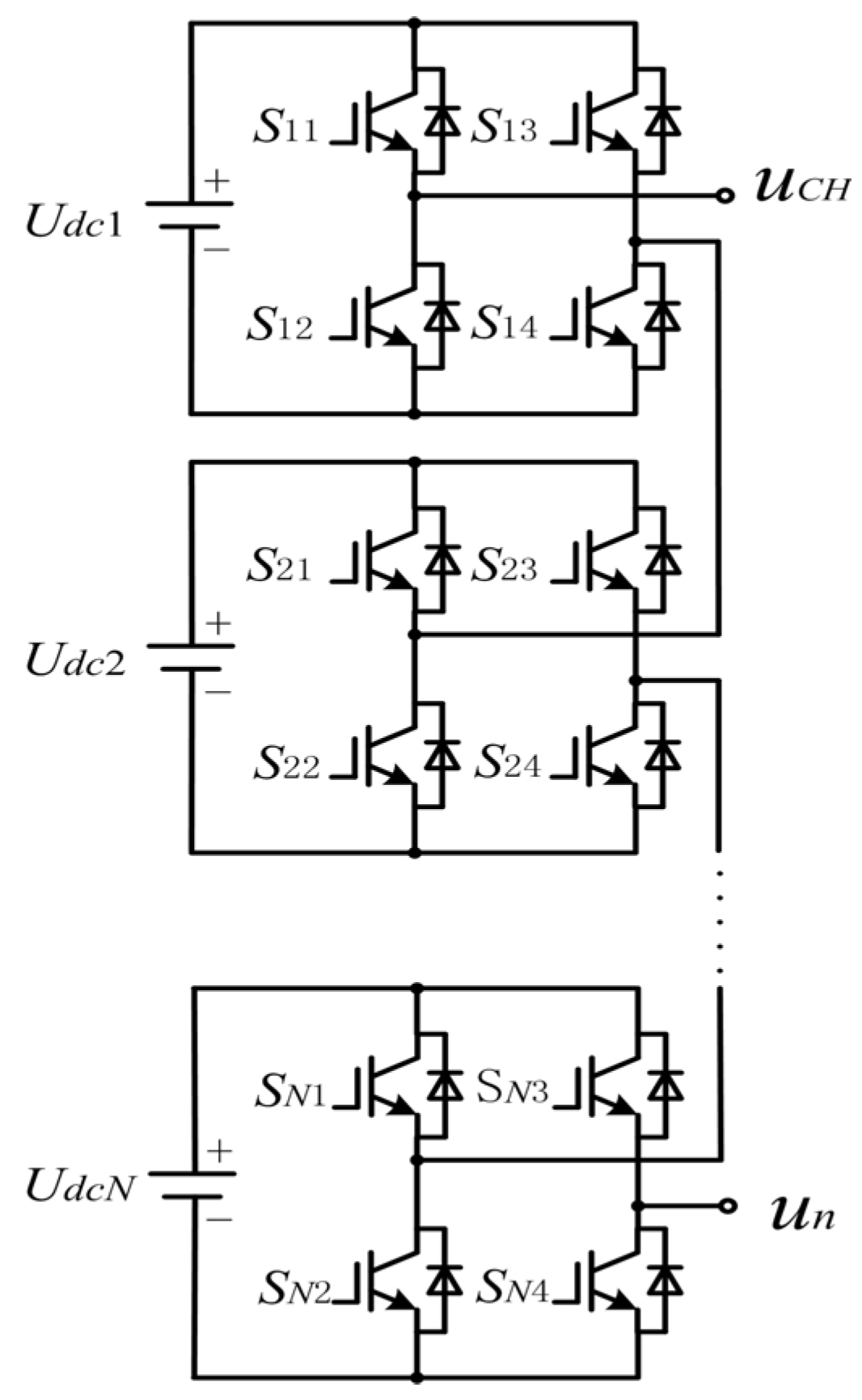
2. The Topology of Cascaded H-bridge Multilevel (CHBML) Inverters and the Low-Frequency Sideband Harmonic Problem
Each single-phase leg in three-phase CHBML inverters includes several cascaded H-bridge cells consisting of a single-phase full-bridge (H-bridge) dc-to-ac converter and an isolated dc source. The topology of a single-phase leg of CHBML inverter is shown in
Figure 1.
Figure 1.
Topology of a single-phase leg of a cascaded H-bridge multilevel (CHBML) inverter.
Figure 1.
Topology of a single-phase leg of a cascaded H-bridge multilevel (CHBML) inverter.
In different applications, the isolated cell dc sources of the CHBML inverter are different. The cell dc sources of grid-connected CHBML inverters that are used in photovoltaic power generation systems are composed of photovoltaic cells and auxiliary circuits, and the cell dc sources used in motor drives are usually composed of some capacitors and a rectifier connected to a multi-winding phase-shifting transformer [
12].
To find the reason why the conventional PSCPWM cannot cancel low-frequency sideband harmonics under the condition of unequal cell dc voltages, the inverter output voltage is first analyzed by use of the double Fourier integral analysis [
30]. For the H-bridge cell for which the asymmetrical regular sampled PWM is adopted, its output voltage can be expressed as:
In Equation (1), ω
s is the frequency of carrier waveform; ω
m is the frequency of modulation waveform;
m is the amplitude modulation index;
Udc is the cell dc voltage; θ
ps is the cell carrier phase;
J1 (
mπ/2),
Jb [
bmπ/(2
kf)] and
Jb (
dmπ/2) are all Bessel functions of the first kind [
31]. The ω
s-to-ω
m ratio
kf and the variable “
d” are defined as:
It can be observed that the cell output voltage shown in Equation (1) is divided into three parts: fundamental wave, baseband harmonics and sideband harmonics. As the output voltage of the single-phase leg is the summation of the cascaded H-bridge cell output voltages, the Fourier expansion of the phase voltage, which is obtained from Equation (1), is as follows:
In Equation (4),
N represents the number of the cascaded cells;
Udch and θ
psh are the dc voltage and the carrier phase of cell
h, respectively. It can be observed from Equation (4) that the carrier phases have no effect on the fundamental wave. On the other hand, when
kf is great enough, the even order baseband harmonics are negligible. In three phase inverters, the third (
b = 3) baseband harmonics are eliminated in the output line voltage, and the magnitude of higher odd order (
b = 5, 7, … ) baseband harmonics is negligible. So this paper does not analyze the baseband harmonics and focuses on the elimination of the sideband harmonics. Then, the expression of the
bth sideband harmonics around
afs (
fs =
ωs/2
π) is separated from Equation (4) and shown in Equation (5):
where:
Equation (5) can be expressed as the summation of phasors, and it is expressed as:
It can be found from Equation (8) that the sideband harmonic can be cancelled if Equation (9) is valid:
If all dc voltages are equal to
Udce, the conventional PSCPWM can be used to completely eliminate the low-frequency sideband harmonics only by setting the carrier phases θ
psh = π(
h − 1)/
N. Under the condition of unequal cell dc voltages, the low-frequency sideband harmonics around 2
fs, 4
fs, … , 2(
N − 1)
fs (
fs = ω
s/2
π) cannot be cancelled by the conventional PSCPWM, because the summation of the low-frequency sideband harmonics of the cascaded H-bridge cells are not zero. As a result, the output power quality is reduced significantly. The magnitude of the low frequency sideband harmonics can be expressed as:
where:
Equation (10) shows the relationship between the magnitude of the low-frequency sideband harmonic and the cell dc voltage difference |Udch − Udcav| when θpsh = π(h − 1)/N. Based on the analysis of this section, an improved PSCPWM, in which the carrier phases are regulated according to different combinations of unequal dc voltages, is presented in the following section.
3. The Proposed Phase-Shifted Carrier Pulse Width Modulation (PSCPWM) Based on Particle Swarm Optimization (PSO)
As can be seen from the analysis in
Section 2, the low-frequency sideband harmonics cannot be cancelled by means of the conventional PSCPWM when the cell dc voltages are not equal. It can be found from (9) that the sideband harmonics around
afs can be eliminated by regulating the carrier phases (θ
psh) according to the different dc voltages. And the principle can be expressed as:
In practical application, one of the cell carrier phases is usually set to zero, so only
N − 1 carrier phases can be regulated. The low-frequency sideband harmonics are more difficult to be filtered and usually produce greater current ripples on the load, so eliminating the low-frequency sideband harmonics is a priority. Since the output voltage sideband harmonics of the H-bridge cell handled by the asymmetrical regular sampled PWM only exist around even times the carrier frequency harmonic, the low-frequency sideband harmonics can be cancelled by regulating the carrier phases, and the principle is expressed as:
It can be observed from Equation (13) that K equations need to be satisfied to eliminate the sideband harmonics. Since only N − 1 carrier phases can be regulated freely, the number of equations that can be satisfied is usually less than or equal to N − 1, when Udch are not equal. On the other hand, since the elimination of the sideband harmonics around each time carrier frequency involves two equations, K must be an even number. Therefore, if N is an even number, K = N − 2; if N is an odd number, K = N − 1.
The calculation of carrier phases needs to solve the nonlinear transcendental equations shown in Equation (13). The calculation is usually complex and time-consuming. This paper presents a method that is a mixture of the PSO algorithm and LUTs. The LUTs include different combinations of unequal cell dc voltages and the corresponding carrier phases. In general, the dc voltages of cell h listed in the table can be expressed as: Udch_nor, Udch_nor − ΔUdc_inter, Udch_nor − 2ΔUdc_inter, ….The symbol Udch_nor denotes the nominal dc voltage of cell h, ΔUdc_inter denotes the difference of the neighbor dc voltage elements listed in the table. In practical, ΔUdc_inter usually interrelates with the upper limit of the sideband harmonic magnitude.
Under the condition that the cell dc voltages are
Udc1_0,
Udc2_0, …,
UdcN_0, the cell carrier phases can be calculated, and they are θ
ps1_0, θ
ps2_0, … , θ
psN_0. When the cell dc voltages deviate and the carrier phases remain, the magnitude of the sideband harmonics can be expressed as:
where:
It is well known that the magnitude of the summation of phasors is less than or equal to the summation of the phasor magnitude. Then an inequality is obtained and expressed as:
When the upper limit of the sideband harmonic magnitude is
ε, the maximum value of Δ
Udch can be obtained from Equation (16):
and Δ
Udc_inter should be less than two times Δ
Udc_max:
The carrier phases listed in the LUTs are calculated by using the approach based on the PSO algorithm. The PSO algorithm was proposed by Kennedy and Eberhart [
32] in 1995. This heuristic method is easy to use and has high searching efficiency. It has been introduced to solve the complex mathematic equations for several modulation techniques, such as SHEPWM and SHMPWM. As Equation (13) refer to a multi-goal optimization, the direct use of the PSO to solve them is difficult. Therefore, Equation (13) is reduced to a single equation that denotes the weighted average of the low-frequency sideband harmonic magnitude at first. On the other hand, it can be observed from Equation (12) that the sideband harmonics around
afs will be eliminated synchronously when the carrier phases are regulated. In other words, all sideband harmonics around
afs are reduced to zero when the 1st (
b = 1) low-frequency sideband harmonic around
afs is eliminated by regulating the carrier phases. And the magnitude of the 1st (
b = 1) low-frequency sideband harmonics is usually greater than the others. For these reasons, Equation (13) is further reduced to the weighted average of the 1st (
b = 1) low-frequency sideband harmonic magnitude as follows:
The coefficient γ
a is the weight factor of the sideband harmonic around
afs In general, γ
2 and γ
4 are greater than the others to mitigate the low-frequency sideband harmonics around
2fs and
4fs better. To reduce the sideband harmonics, the objective function obtained from Equation (19) must be minimized, which can be expressed as:
As mentioned in
Section 3, the first cell carrier phase θ
ps1 is usually set to zero. In other words, only
N − 1 carrier phases need be calculated. For this reason, each particle position is a
N − 1 dimension vector θ
i = [θ
ps2_i, θ
ps3_i,
…, θ
psN_i], and the
hth element is the carrier phase of the
hth cascaded H-bridge cell. Each particle owns a velocity vector
Vi = [
Vps2_i,
Vps3_i,
…,
VpsN_i]. Each particle refines its search by using its velocity vector, its own experience and the experience of the other particles. The best position of the particle
i found so far is called the personal best, and the best in entire swarm is called the global best. The major procedure of calculating the carrier phases is as follows:
1) Setting the basic data for the algorithm, such as the number of particles, the maximum iteration number iter_max, cogitative parameter φ1 and social parameter φ2, inertia weight factor w, and the maximum velocity Vmax.
2) Setting the initial particle positions θi(0) and velocity vectors Vi(0). Each element of θi(0) is determined as random value between 0 and π, and each element of Vi(0) is initially determined as random value between −Vmax and Vmax.
3) Initializing the personal best positions θi_l and the global best position θg The initial personal best position of the ith particle θi_l is the initial position θi(0). Each particle is evaluated by use of the objective function (20), and the initial global best position θg is the best among the initial positions.
4) Updating the velocity vectors and the position vectors according to Equations (21) and (22), respectively:
In Equations (21) and (22), rand(0,1) represents a random value between 0 and 1.
5) Updating the personal best positions θi_l and the global best position θg The current position of the ith particle θi(k + 1) is evaluated by use of the objective function. If the result is better than the personal best position θi_l, θi_l is replaced with θi(k + 1). If the result is better than the global best position θg, θg is replaced with θi(k + 1).
6) Adding 1 to the iteration counter and repeating steps (4)–(6) until the iteration counter reaches iter_max.
It can be seen from Equation (19) that the carrier phases must be calculated according to different dc voltages. Take for example the CHBML inverter in which each phase leg is composed of three cascaded H-bridge cells. The dc voltages of the first and third cells are 0.701 times and 1.01 times the nominal dc voltage, respectively, and the dc voltage of the second cell is changing between 0.4 times and 1.0 times the nominal dc voltage when Δ
Udc_inter is equal to 0.01 times the nominal dc voltage. The first cell carrier phase θ
ps1 is zero. Two calculated carrier phases θ
ps2 and θ
ps3 that are stored in the LUTs are shown in
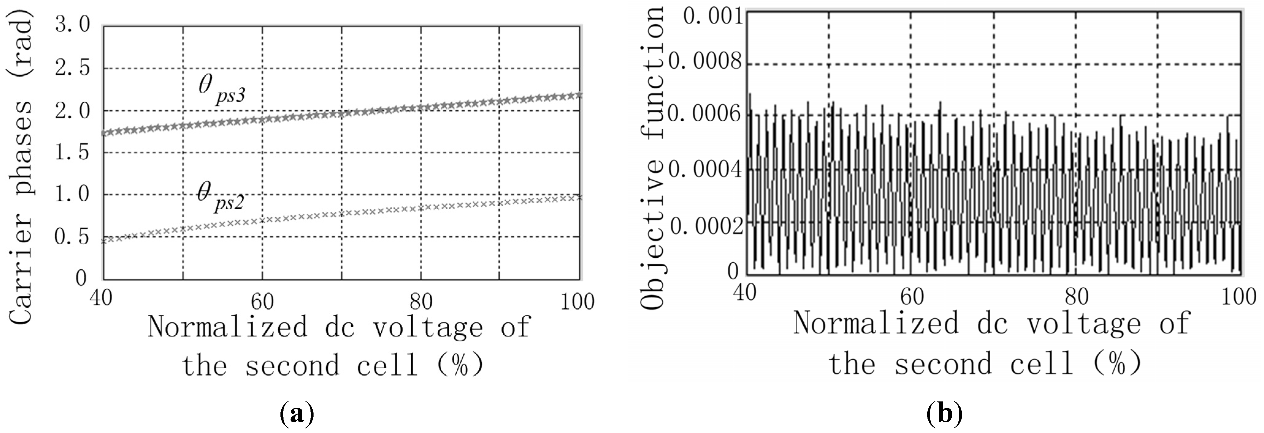
Figure 2a, when Δ
Udc_inter of the dc voltage of cell 2 is equal to 0.01 times the nominal dc voltage.
Figure 2b shows the weighted average of the 1st (
b = 1) low-frequency sideband harmonic magnitude under the condition: 1) the dc voltage of cell 2 changes continuously; 2) the carrier phases are obtained by looking up the carrier phases shown in
Figure 2a.
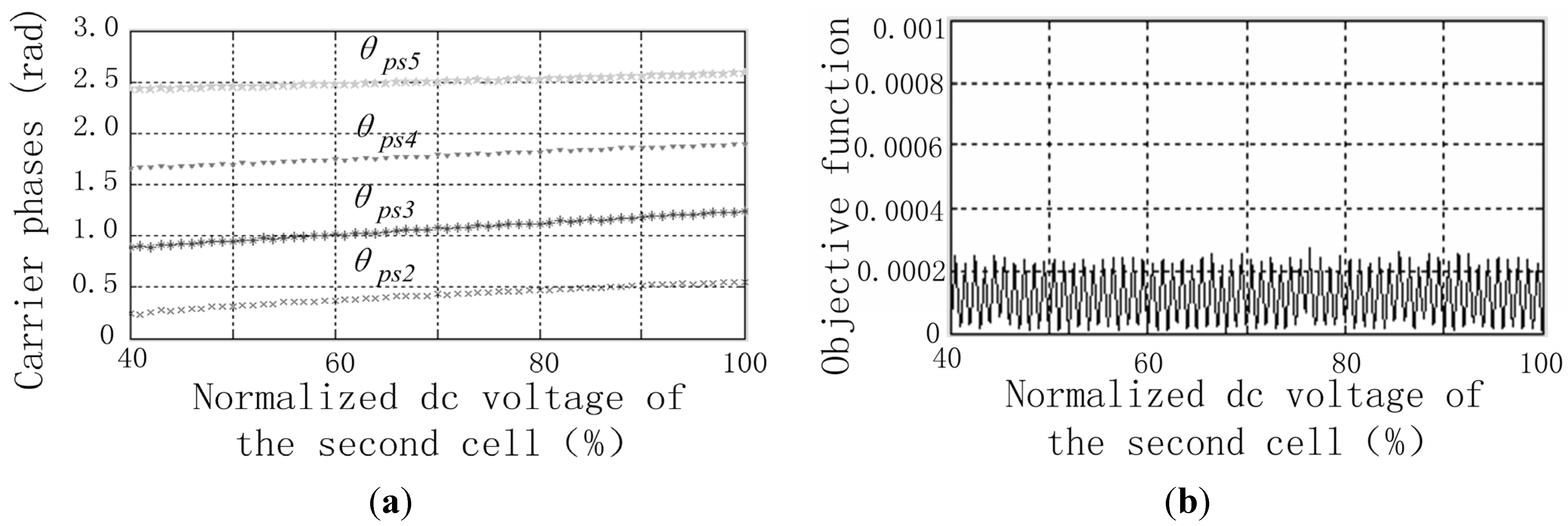
Another example is the inverter in which each phase leg includes five cascaded H-bridge cells. The dc voltages of the first and 3rd–5th cells are 0.7, 0.99, 1.0 and 1.01 times the nominal dc voltage, respectively, and the second cell dc voltage changes between 0.4 times and 1.0 times the nominal dc voltage. As mentioned previously, the first cell carrier phase θ
ps1 is zero. Four calculated carrier phases θ
ps2, θ
ps3, θ
ps4 and θ
ps5 that are stored in the LUTs are shown in
Figure 3a when Δ
Udc_inter of the dc voltage of cell 2 is equal to 0.01 times the nominal dc voltage.
Figure 3b shows the weighted average of the 1st (
b = 1) low-frequency sideband harmonic magnitude under the condition: 1) the dc voltage of cell 2 changes continuously; 2) the carrier phases are obtained by looking up the carrier phases shown in
Figure 3a.
Figure 2.
(a) Two calculated carrier phases; and (b) values of the objective function.
Figure 2.
(a) Two calculated carrier phases; and (b) values of the objective function.
Figure 3.
(a) Four calculated carrier phases; and (b) values of the objective function.
Figure 3.
(a) Four calculated carrier phases; and (b) values of the objective function.
Figure 2 and
Figure 3 show that the carrier phases can be calculated by use of the presented approach based on the PSO algorithm. It can be observed from
Figure 2b and
Figure 3b that: the weighted average of the magnitude of the 1st low-frequency sideband harmonics can be limited to an acceptable level.
4. Simulation
In order to verify the theoretical analysis and the proposed PSCPWM, a mathematic model of the CHBML inverter is established by means of MATLAB/SIMULINK. The topology of a single phase leg of the three-phase CHBML inverter is shown in
Figure 1. Each single-phase leg includes five cascaded H-bridge cells. The fundamental wave frequency is 50 Hz, and the cell carrier wave frequency is 300 Hz. The amplitude modulation index of each cell is 0.99. Two combinations of different cell dc voltages, the carrier phases of the conventional PSCPWM and the proposed PSCPWM, are shown in
Table 1.
Table 1.
DC voltages and carrier phases of the cells. PSCPWM: phase-shifted carrier pulse width modulation.
Table 1.
DC voltages and carrier phases of the cells. PSCPWM: phase-shifted carrier pulse width modulation.
| Contents | Cell 1 | Cell 2 | Cell 3 | Cell 4 | Cell 5 |
|---|
| Udch | 685 V | 395 V | 970 V | 980 V | 985 V |
| θpsh of the conventional PSCPWM | 0 | π/5 | 2π/5 | 3π/5 | 4π/5 |
| θpsh of the proposed PSCPWM | 0 | 0.236 | 0.887 | 1.653 | 2.421 |
| Udch | 685 V | 690 V | 970 V | 980 V | 985 V |
| θpsh of the conventional PSCPWM | 0 | π/5 | π/5 | 3π/5 | 4π/5 |
| θpsh of the proposed PSCPWM | 0 | 0.420 | 1.065 | 1.780 | 2.497 |
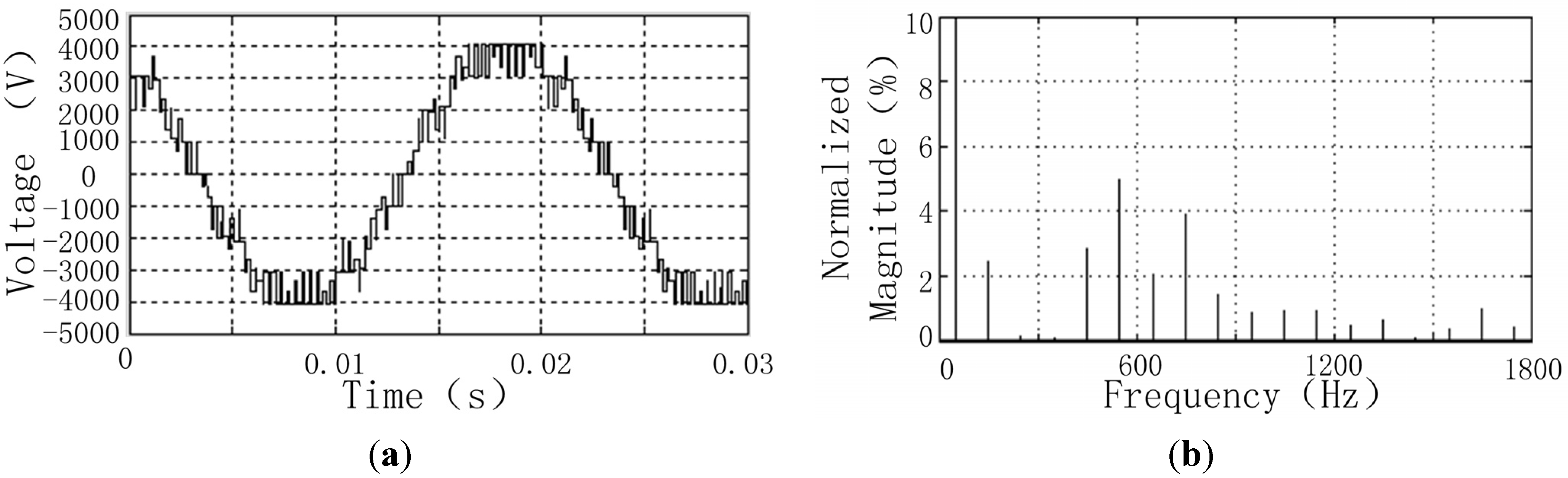
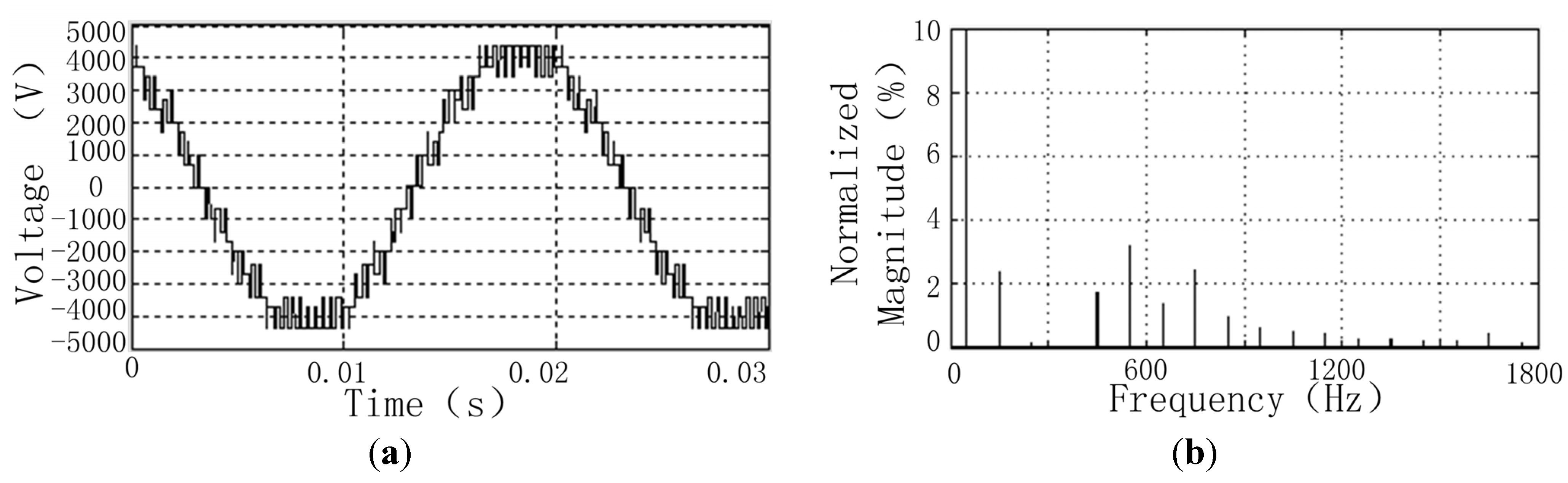
Figure 4 shows the phase voltage waveform and the corresponding harmonic components obtained from the conventional PSCPWM when the dc voltage of the second cell is 395 V. The phase voltage waveform and the harmonic components of the proposed PSCPWM are shown in
Figure 5.
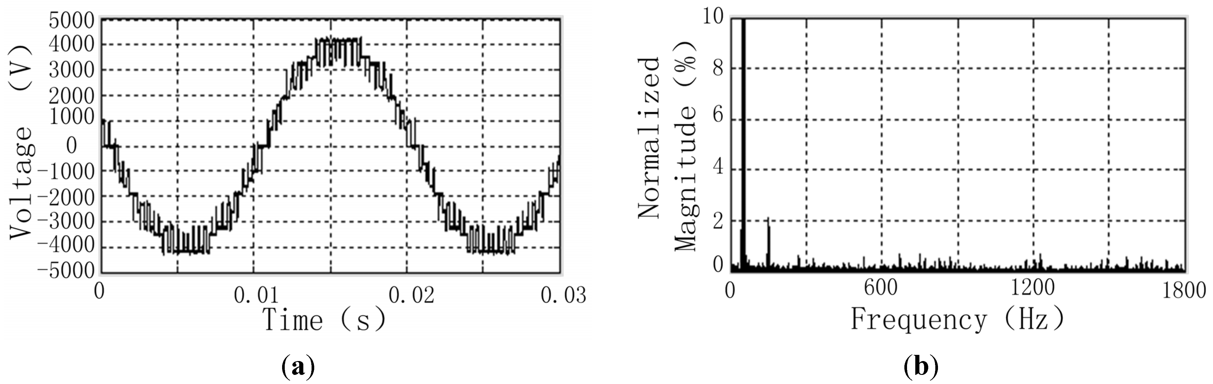
Figure 6 shows the conventional PSCPWM phase voltage waveform and harmonic components;
Figure 7 shows the proposed PSCPWM phase voltage waveform and harmonic components when the second cell dc voltage is 690 V.
Figure 4.
Result of the conventional PSCPWM when the second cell dc voltage is 395 V: (a) output voltage waveform; and (b) harmonics.
Figure 4.
Result of the conventional PSCPWM when the second cell dc voltage is 395 V: (a) output voltage waveform; and (b) harmonics.
Figure 5.
Result of the proposed PSCPWM when the second cell dc voltage is 395 V: (a) output voltage waveform; and (b) harmonics.
Figure 5.
Result of the proposed PSCPWM when the second cell dc voltage is 395 V: (a) output voltage waveform; and (b) harmonics.
Figure 6.
Result of the conventional PSCPWM when the second cell dc voltage is 690 V: (a) output voltage waveform; and (b) harmonics.
Figure 6.
Result of the conventional PSCPWM when the second cell dc voltage is 690 V: (a) output voltage waveform; and (b) harmonics.
Figure 7.
Result of the proposed PSCPWM when the second cell dc voltage is 690 V: (a) output voltage waveform; and (b) harmonics.
Figure 7.
Result of the proposed PSCPWM when the second cell dc voltage is 690 V: (a) output voltage waveform; and (b) harmonics.
As seen from the harmonic components shown in
Figure 4 and
Figure 6, the conventional PSCPWM cannot eliminate the sideband harmonics around 600 Hz (2
fs) and 1200 Hz (4
fs) when the dc voltages are not equal.
Figure 5 and
Figure 7 show that the sideband harmonics around 600 Hz and 1200 Hz can be almost completely eliminated when the proposed PSCPWM is utilized.
In order to further verify the proposed PSCPWM, the simulations with five combinations of unequal cell dc voltages have been made. The five combinations of unequal dc voltages and the carrier phases are listed in
Table 2; the carrier phases of the conventional PSCPWM are θ
psh = (
h − 1)π/5. The corresponding magnitude of the significant sideband harmonics around 600 Hz (2
fs) and 1200 Hz (4
fs) is shown in
Table 3. According to
Table 2 and
Table 3, the magnitude of the significant low-frequency sideband harmonics increases as the second cell dc voltage drops, when the conventional PSCPWM is applied. All the significant sideband harmonics around 600 Hz and 1200 Hz can be almost completely eliminated when the proposed PSCPWM is applied.
Table 2.
Different combinations of unequal cell dc voltages and the carrier phases.
Table 2.
Different combinations of unequal cell dc voltages and the carrier phases.
| No. | Contents | Cell 1 | Cell 2 | Cell 3 | Cell 4 | Cell 5 |
|---|
| 1 | Udch | 685 V | 636 V | 970 V | 980 V | 985 V |
| θpsh | 0 | 0.403 | 1.036 | 1.763 | 2.487 |
| 2 | Udch | 685 V | 587 V | 970 V | 980 V | 985 V |
| θpsh | 0 | 0.377 | 1.009 | 1.742 | 2.473 |
| 3 | Udch | 685 V | 539 V | 970 V | 980 V | 985 V |
| θpsh | 0 | 0.347 | 0.979 | 1.721 | 2.461 |
| 4 | Udch | 685 V | 489 V | 970 V | 980 V | 985 V |
| θpsh | 0 | 0.316 | 0.950 | 1.700 | 2.449 |
| 5 | Udch | 685 V | 440 V | 970 V | 980 V | 985 V |
| θpsh | 0 | 0.278 | 0.918 | 1.677 | 2.435 |
Table 3.
Sideband harmonics around 600 Hz and 1200 Hz obtained from the simulations when the conventional PSCPWM and the proposed PSCPWM are used respectively under different combinations of unequal dc voltages.
Table 3.
Sideband harmonics around 600 Hz and 1200 Hz obtained from the simulations when the conventional PSCPWM and the proposed PSCPWM are used respectively under different combinations of unequal dc voltages.
| No. | Modulation techniques | Normalized magnitude of sideband harmonics around 600 Hz and 1200 Hz |
|---|
| 450 Hz | 550 Hz | 650 Hz | 750 Hz | 1050 Hz | 1150 Hz | 1250 Hz | 1350 Hz |
|---|
| 1 | Conventional PSCPWM | 1.89% | 3.43% | 1.49% | 2.63% | 0.48% | 0.47% | 0.26% | 0.16% |
| Proposed PSCPWM | 0.012% | 0.012% | 0.012% | 0.013% | 0.014% | 0.013% | 0.013% | 0.012% |
| 2 | Conventional PSCPWM | 2.07% | 3.76% | 1.63% | 2.89% | 0.58% | 0.55% | 0.30% | 0.16% |
| Proposed PSCPWM | 0.015% | 0.015% | 0.015% | 0.014% | 0.017% | 0.017% | 0.018% | 0.018% |
| 3 | Conventional PSCPWM | 2.26% | 4.10% | 1.78% | 3.15% | 0.68% | 0.64% | 0.35% | 0.18% |
| Proposed PSCPWM | 0.017% | 0.016% | 0.014% | 0.015% | 0.017% | 0.016% | 0.017% | 0.019% |
| 4 | Conventional PSCPWM | 2.46% | 4.46% | 1.93% | 3.43% | 0.80% | 0.74% | 0.41% | 0.21% |
| Proposed PSCPWM | 0.018% | 0.019% | 0.018% | 0.017% | 0.019% | 0.019% | 0.018% | 0.021% |
| 5 | Conventional PSCPWM | 2.66% | 4.83% | 2.09% | 3.71% | 0.92% | 0.86% | 0.47% | 0.24% |
| Proposed PSCPWM | 0.012% | 0.013% | 0.014% | 0.012% | 0.015% | 0.022% | 0.024% | 0.015% |
5. Experiment
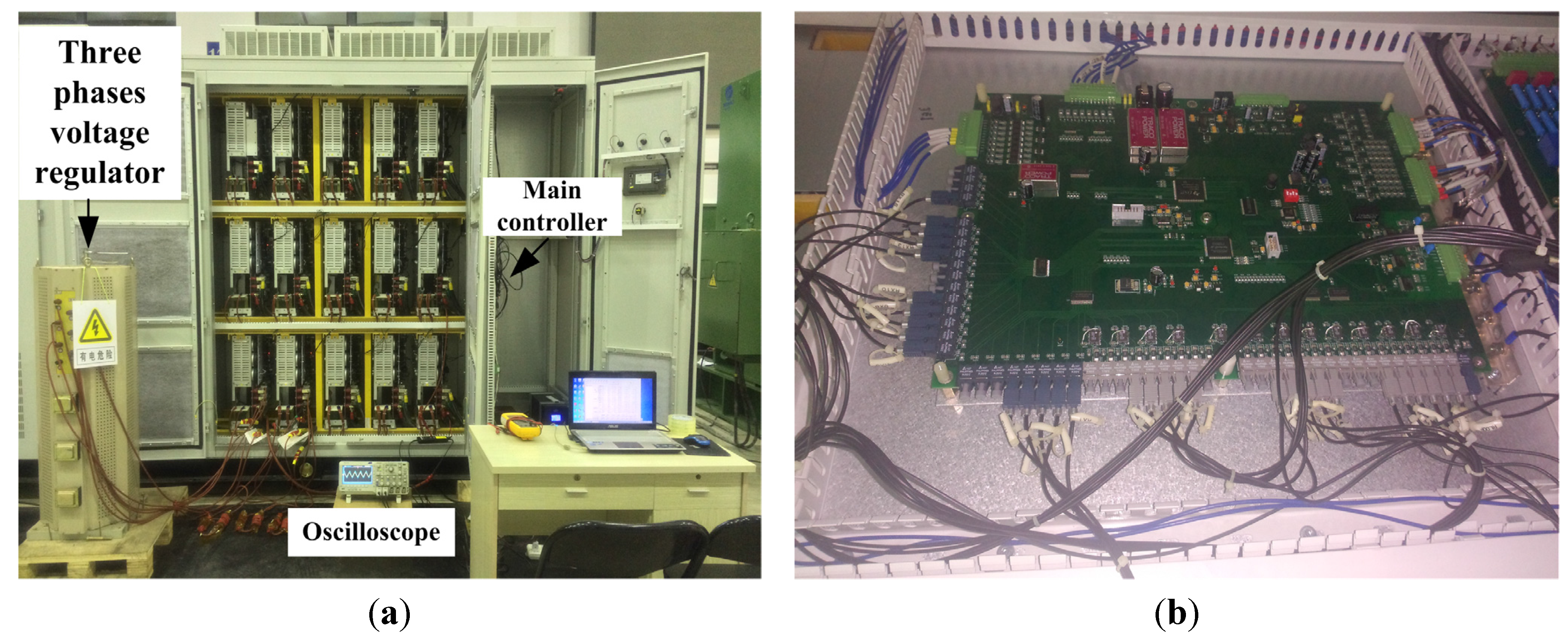
Experiments have been carried out on a 2.5 MVA CHBML inverter (lab prototype) to verify the proposed PSCPWM technique. The topology and the parameters of the inverter are identical to those of the simulation model. This inverter includes three phase leg. Each phase leg of the inverter consists of five cells. The input voltage of the second cell of phase C is regulated by a three-phase voltage regulator, and then, the dc voltage of this cell changes between 395 V and 690 V.
Figure 8a shows the inverter, the three phase voltage regulator, the oscilloscope and the computer that is used to monitor the inverter. The control system of the inverter consists of the main controller, the cell controllers and the communication devices. Each controller is composed of the low-cost DSP (TMS320F28335, Texas Instruments, Dallas, TX, USA) and its auxiliary circuit. The main controller, which is installed in the right side of the inverter and shown in
Figure 8b, generates the voltage (current) command value and calculates the cell carrier phases. It also has the functions of monitoring, observation, protection, human-machine interface as well as other auxiliary functions of the system. The cell controller installed in the H-bridge cell is used to regulate the cell carrier phase and generate PWM signals. Besides, it can perform functions of monitoring and protection. The voltage waveform are captured and saved by use of a digital oscilloscope, and the harmonic components are obtained by use of the fast Fourier transformation function of the oscilloscope.
Figure 8.
2.5 MVA CHBML inverter: (a) inverter and major experimental devices; and (b) main controller.
Figure 8.
2.5 MVA CHBML inverter: (a) inverter and major experimental devices; and (b) main controller.
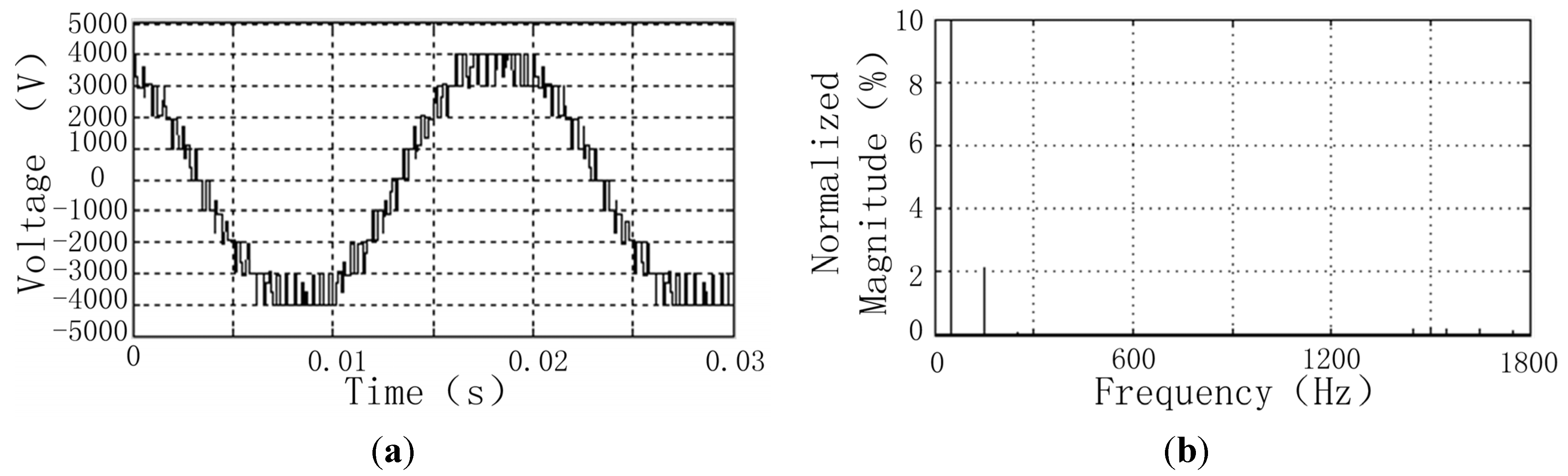
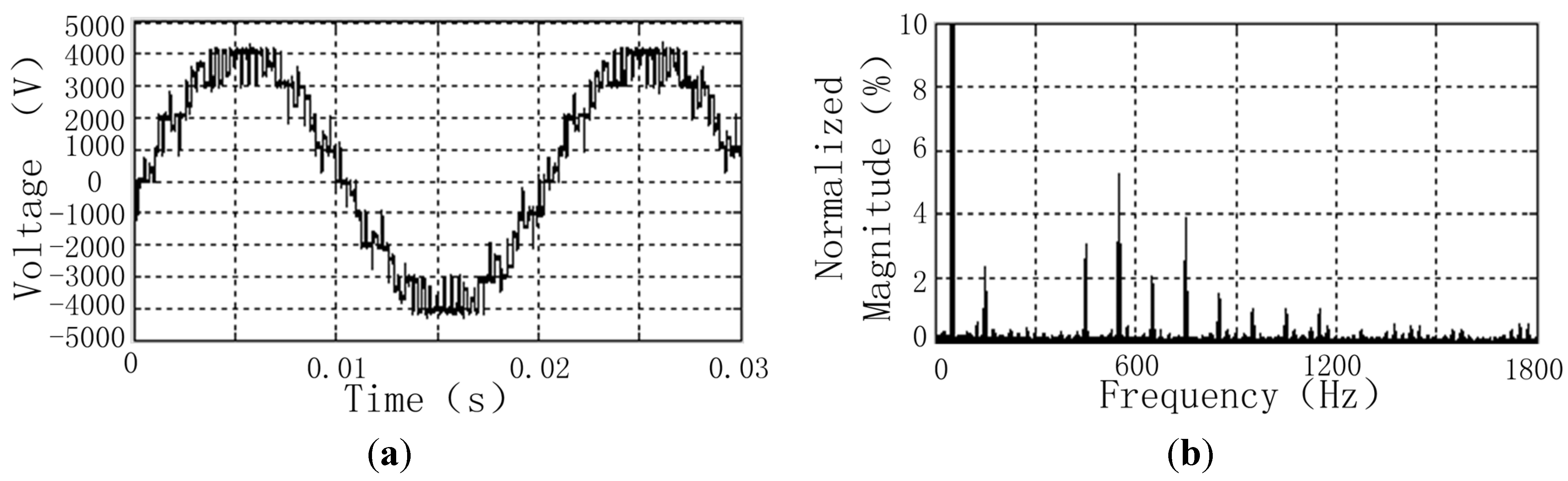
Figure 9 shows the phase voltage waveform and harmonic components of the conventional PSCPWM.
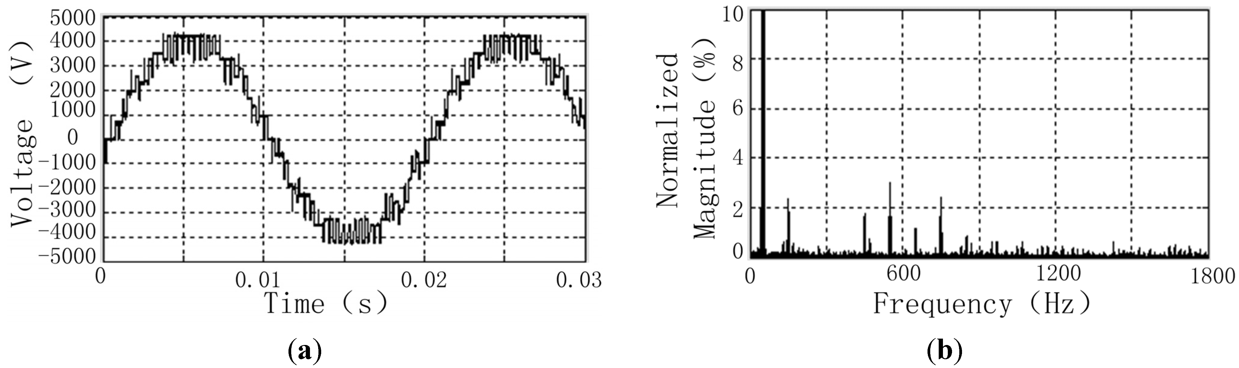
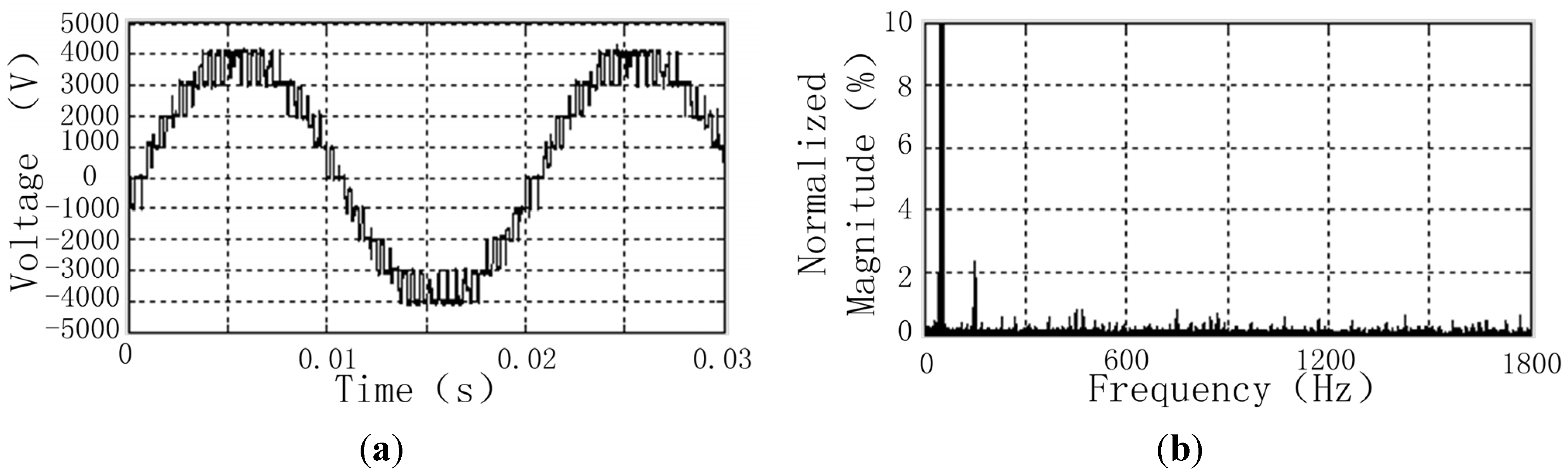
Figure 10 shows the phase voltage waveform and harmonic components when the proposed PSCPWM is used.
Figure 9 and
Figure 10 are all obtained under the conditions: 1) the dc voltage of cell 2 is 395 V; 2) the dc voltages of the first and 3rd–5th cells are 685 V, 970 V, 980 V and 985 V, respectively.
Figure 11 and
Figure 12 show the experimental results of the conventional PSCPWM and the proposed PSCPWM respectively under the conditions: 1) the dc voltage of cell 2 is 690 V; 2) the dc voltages of the first and 3rd–5th cells are also 685 V, 970 V, 980 V and 985 V, respectively. The carrier phases are listed in
Table 1.
Figure 9.
Result of the conventional PSCPWM when the second cell dc voltage is 395 V: (a) output voltage waveform; and (b) harmonics.
Figure 9.
Result of the conventional PSCPWM when the second cell dc voltage is 395 V: (a) output voltage waveform; and (b) harmonics.
It can be found from
Figure 9 and
Figure 11 that the conventional PSCPWM is unable to cancel the sideband harmonics around 600 Hz and 1200 Hz.
Figure 10 and
Figure 12 show that the proposed PSCPWM can reduce the low-frequency sideband harmonics around 600 Hz and 1200 Hz under different combinations of unequal cell dc voltages. The magnitude of the low-frequency sideband harmonics is less than one percent of the fundamental waveform magnitude.
Figure 10.
Result of the proposed PSCPWM when the second cell dc voltage is 395 V: (a) output voltage waveform; and (b) harmonics.
Figure 10.
Result of the proposed PSCPWM when the second cell dc voltage is 395 V: (a) output voltage waveform; and (b) harmonics.
Figure 11.
Result of the conventional PSCPWM when the second cell dc voltage is 690 V: (a) output voltage waveform; and (b) harmonics.
Figure 11.
Result of the conventional PSCPWM when the second cell dc voltage is 690 V: (a) output voltage waveform; and (b) harmonics.
Figure 12.
Result of the proposed PSCPWM when the second cell dc voltage is 690 V: (a) output voltage waveform; and (b) harmonics.
Figure 12.
Result of the proposed PSCPWM when the second cell dc voltage is 690 V: (a) output voltage waveform; and (b) harmonics.
Furthermore, more experiments have been carried out under the condition that the dc voltage of cell 2 changes between 440 V and 636 V. The five combinations of unequal dc voltages and the carrier phases of the proposed PSCPWM are listed in
Table 2 too; the carrier phases of the conventional PSCPWM are θ
psh = (
h − 1)π/5. The corresponding magnitude of the significant sideband harmonics around 600 Hz (2
fs) and 1200 Hz (4
fs) is shown in
Table 4.
Table 4.
Sideband harmonics around 600 Hz and 1200 Hz obtained from the prototype experiments when the conventional PSCPWM and the proposed PSCPWM are used respectively under different combinations of unequal dc voltages.
Table 4.
Sideband harmonics around 600 Hz and 1200 Hz obtained from the prototype experiments when the conventional PSCPWM and the proposed PSCPWM are used respectively under different combinations of unequal dc voltages.
| No. | Modulation techniques | Normalized magnitude of sideband harmonics around 600 Hz and 1200 Hz |
|---|
| 450 Hz | 550 Hz | 650 Hz | 750 Hz | 1050 Hz | 1150 Hz | 1250 Hz | 1350 Hz |
|---|
| 1 | Conventional PSCPWM | 1.80% | 3.30% | 1.33% | 2.82% | 0.51% | 0.43% | 0.23% | 0.15% |
| Proposed PSCPWM | 0.55% | 0.31% | 0.19% | 0.55% | 0.19% | 0.23% | 0.19% | 0.15% |
| 2 | Conventional PSCPWM | 1.97% | 3.45% | 1.38% | 2.91% | 0.71% | 0.55% | 0.39% | 0.23% |
| Proposed PSCPWM | 0.52% | 0.40% | 0.24% | 0.52% | 0.12% | 0.16% | 0.12% | 0.20% |
| 3 | Conventional PSCPWM | 2.32% | 4.08% | 1.64% | 3.32% | 0.72% | 0.68% | 0.32% | 0.44% |
| Proposed PSCPWM | 0.40% | 0.32% | 0.16% | 0.69% | 0.16% | 0.12% | 0.16% | 0.20% |
| 4 | Conventional PSCPWM | 2.55% | 4.37% | 1.82% | 3.68% | 0.69% | 0.56% | 0.48% | 0.20% |
| Proposed PSCPWM | 0.49% | 0.32% | 0.20% | 0.73% | 0.16% | 0.24% | 0.20% | 0.20% |
| 5 | Conventional PSCPWM | 2.61% | 4.61% | 1.81% | 3.70% | 0.86% | 0.78% | 0.53% | 0.45% |
| Proposed PSCPWM | 0.49% | 0.29% | 0.16% | 0.83% | 0.20% | 0.12% | 0.20% | 0.16% |
It can be observed from
Figure 10,
Figure 12 and
Table 4 that all the significant sideband harmonics around 600 Hz and 1200 Hz can be limited to a low level when the proposed PSCPWM is applied. Comparing the experimental results and the simulations of the conventional PSCPWM, which are shown in
Figure 4,
Figure 6,
Figure 9 and
Figure 11,
Table 3 and
Table 4, the corresponding sideband harmonics are almost equal. Comparing the experimental results and the simulations of the proposed PSCPWM, which are shown in
Figure 5,
Figure 7,
Figure 10, and
Figure 12,
Table 3 and
Table 4, the low-frequency sideband harmonics of the prototype experiments are slightly greater than the simulation results because of the inevitable measuring error of dc voltages and the synchronization error of cell carrier phases.


