
Theoretical Modelling Methods for Thermal Management of Batteries

School of Aerospace, Mechanical and Manufacturing Engineering, Royal Melbourne Institute of Technology, Bundoora 3083, Victoria, Australia
*
Author to whom correspondence should be addressed.
Energies 2015, 8(9), 10153-10177; https://doi.org/10.3390/en80910153
Submission received: 17 August 2015
/
Revised: 30 August 2015
/
Accepted: 9 September 2015
/
Published: 17 September 2015
(This article belongs to the Special Issue Electrochemical Energy Storage - 2015)
Abstract
:The main challenge associated with renewable energy generation is the intermittency of the renewable source of power. Because of this, back-up generation sources fuelled by fossil fuels are required. In stationary applications whether it is a back-up diesel generator or connection to the grid, these systems are yet to be truly emissions-free. One solution to the problem is the utilisation of electrochemical energy storage systems (ESS) to store the excess renewable energy and then reusing this energy when the renewable energy source is insufficient to meet the demand. The performance of an ESS amongst other things is affected by the design, materials used and the operating temperature of the system. The operating temperature is critical since operating an ESS at low ambient temperatures affects its capacity and charge acceptance while operating the ESS at high ambient temperatures affects its lifetime and suggests safety risks. Safety risks are magnified in renewable energy storage applications given the scale of the ESS required to meet the energy demand. This necessity has propelled significant effort to model the thermal behaviour of ESS. Understanding and modelling the thermal behaviour of these systems is a crucial consideration before designing an efficient thermal management system that would operate safely and extend the lifetime of the ESS. This is vital in order to eliminate intermittency and add value to renewable sources of power. This paper concentrates on reviewing theoretical approaches used to simulate the operating temperatures of ESS and the subsequent endeavours of modelling thermal management systems for these systems. The intent of this review is to present some of the different methods of modelling the thermal behaviour of ESS highlighting the advantages and disadvantages of each approach.
1. Introduction
Energy Storage Systems (ESS) using batteries has already started to make a sizeable impact on the renewable energy storage market. The technology is attractive in applications such as solar powered telecommunication towers [1]. The uptake of ESS is eminent given the technology’s falling costs and the rising cost of grid electricity. Developers are already beginning to deploy pilot ESS battery banks to test their integration with the electricity grid [2]. One of the important parameter that affects the performance of ESS is the operating temperature of the system. The operating temperature affects many aspects of an ESS including round trip energy efficiency, charge acceptance, reliability, lifetime and life cycle cost [3,4,5].
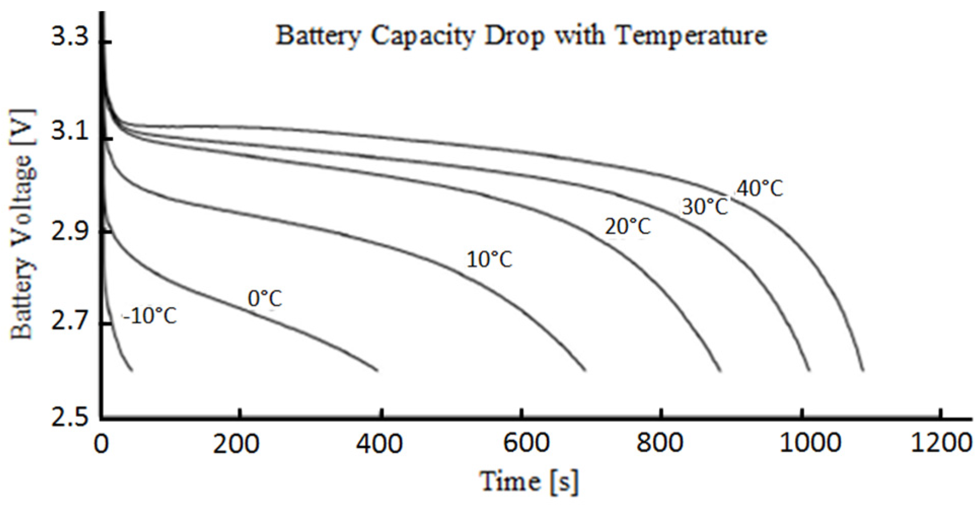
Operating an ESS in cold climates reduces the system energy storage capacity and charge acceptance during charging [6,7,8,9,10,11,12]. Research have found that the capacity of Li-ion batteries can decrease as much as 95% when the ESS is operating at −10 °C compared to that at 20 °C [13]. Figure 1 supports the previous statement illustrating the reduction in ESS capacity for a Li-ion battery operating at various temperatures in a temperature control test for a 3C discharge rate (current rate at which the battery can be fully discharged in 3 hours). Lead-acid (LA) batteries also suffer from a significant drop in capacity at lower operating temperatures [14]. This drop in the energy storage capacity of battery-based ESS is not acceptable in many applications, making the business case for adopting the technology much less attractive. The lifetime of batteries is also adversely affected when operating at high temperature conditions [15,16,17,18]. Motloch, et al. [19] states that for every 1 °C increase of cell temperature the lifetime of a Li-ion battery reduces by approximately two months in an operating temperature range of 30 to 40 °C. As another example: experimental studies conducted in America have shown that for Electric Vehicles (EVs) mileage declined approximately 60% when the ambient temperature dropped below −6 °C and the mileage also dropped 33% when the ambient temperature exceeded 35 °C [20,21]. Another factor that affects the lifetime of an ESS is the cell temperature distribution. The cell temperature difference must be limited to below 5 °C to maximise the ESS lifetime [22,23]. Large temperature non-uniformity in the ESS pack reduces the overall cell lifespan as well as available cell capacity [24,25,26,27].
That is why significant research efforts have been dedicated to the thermal management of batteries. For example many studies have been focused on vehicular applications specifically electric vehicles (EV) and hybrid electric vehicles (HEV) with many of the recent theoretical and experimental research efforts also have been aimed towards EV battery operation [28,29,30]. The high charge and discharge rates of batteries used in these applications warrant a well-designed thermal management systems [31]. The different types of batteries that have been tested to meet the energy storage requirements in vehicular applications include lead acid, Li-ion, ultra-battery (supercapacitor and lead acid battery combination) and Nickel/metal hydride type technologies [32,33,34,35,36]. Amongst these battery types used for ESS, Li-ion has been the dominant type for vehicular applications due to its energy and power densities, durability and safety compared to the other types [37,38].
Figure 1.
Experimental results indicating Li-ion battery discharge curves at various temperatures for a 3C discharge rate [39].
Figure 1.
Experimental results indicating Li-ion battery discharge curves at various temperatures for a 3C discharge rate [39].

Zhang, et al. [30] identified the safe temperature limits of the Li-ion in their research as −10 to 50 °C. Other sources state that Li-ion batteries are adversely affected when the ambient temperature is outside the range of 0 to 65 °C [40]. Many literature works have identified the ideal operating temperature of Li-ion batteries being in between 20 and 30 °C [41]. At this temperature the Li-ion ESS is near its maximum capacity and the degradation effects is minimised. Similarly LA batteries have been tested to safely function between −20 and 50 °C with the ideal operating temperature being in between 20 and 27 °C [42] that is close to that suggested for Li-ion batteries (i.e., 20 and 30 °C) [41]. Operating LA batteries below −20 °C is known to cause freezing highly likely leading to permanent damage. The general relationship between discharge time and operating temperature of LA batteries is the same as that for Li-ion batteries. Experimental tests showed a 22.5% increase in discharge time for a constant current constant voltage (CCCV) discharge at 25 °C compared to 50 °C [43].
As already discussed, there has been many research done into modelling the thermal behaviour of battery ESS since the late 1970s [44]. The research efforts were propelled when researchers in their investigation of ESS found that the battery performance was significantly affected by the operating temperature of the battery module and the temperature variation/distribution within the battery modules [31]. Since then researchers have been striving to design thermal models that could accurately predict the temperature dependent performance of battery-based ESS while balancing the computational requirements of the models. In these models the equations for thermal behaviour are based on [45]:
- The energy balance equation
- The heat generation equation—complex or simplified
- The boundary condition equations—linear/nonlinear, conduction, convection and or radiation
There have been many efforts to model the heat generation and thermal management of such ESS from simplified lumped parameters models [3,40], to adaptive theoretical models with experimental calibration [44] and computationally intense 3-dimensional numerical models [46,47]. Most of these researches had vehicular applications in their core.
The focus of this paper is to present a review of some methods used to model and simulate the thermal behaviour of ESS. This review will depict some of the various methods of thermal modelling that has been investigated and/or applied to date. Most of these investigations were for HEV and EV applications however the approaches used in HEV/EV applications can be adopted for the renewable energy storage applications. The operating conditions which vary in both applications can be treated as a separate unique input into these models. Additionally the entire ESS consists of the management system, control and communication in addition to the batteries. The focus of this paper is on the battery side of the ESS and the term ESS referred to in this review emphasises on the battery side of the system. In the following sections the modelling techniques, governing equations, as well as the physical variable inputs and assumptions are reviewed. Some of the results and the important findings will be discussed and also the advantages and disadvantages of certain elements of these modelling approaches are discussed. The last part of each section highlights the applications of thermal modelling used in the design of thermal management for battery based ESS.
2. Numerical and Analytical Thermal Models
2.1. Overview of Numerical and Analytical Models
Numerical and analytical models use differential equations to solve for the energy balance in the ESS [48]. One of the core components of the energy balance equation, the internal heat generation in the ESS is attributed to the temperature-current dependent overpotential heat generation and state of charge (SOC) dependent change in entropy heat generation. Overpotential heat generation is always positive and is caused by the internal resistance within the battery, kinetic aspects and mass transport associated with electrochemical reactions [9]. Heat generation due to entropy change on the other hand can be positive or negative and is attributed to the reversible electrochemical reactions within the battery. Heat generation from the enthalpy of mixing is also another source of internal heat generation but it is normally neglected in many models.
Convection is normally the main method for heat dissipation with radiation sometimes considered in some models. Conduction is either deliberated or simplified by assuming that the temperature inside the cell is uniform. Numerical models are generally time consuming and computationally intense; however, if setup properly with sound experimental data, these models have the potential to produce very accurate results.
2.2. Lumped Capacitance Thermal Models
Lumped capacitance thermal modelling is a transient conduction approach that assumes the temperature of a solid is spatially uniform and is a function of time (t) only. This implies that there are negligible temperature gradients in a solid and that the thermal conductivity (k) is infinite. In reality this is not true however it can be approximated only if the thermal resistance to conduction within the solid is significantly less than the thermal resistance to convection between the solid and the surrounding:
where k represents the conduction heat transfer coefficient of the cell (W·m−1·K−1), h is the convection heat transfer coefficient (W·m−2·K−1) and Lc is the characteristic length (m):
in which V and A are the volume (m3) and the surface area (m2) of the solid respectively. The premise in Equation (1) formulates the dimensionless Biot (Bi) number:
Bi physically represents the ratio of the heat transfer resistances inside and at the surface of the battery. To comply with the assumption of spatial temperature uniformity within the solid, the Bi has to be significantly less than 1 to be applied in this approximation method. A Bi < 0.1 would yield an error of <5% in a transient heat transfer model [49]. Thus it is commonly assumed that the lumped capacitance method is acceptable for situations with Bi < 0.1. If the Bi number is >1 this means that there would be temperature gradients within the body. The overall energy balance of the solid is given as:
where ρ is the density of the solid (kg·m−3), V is the volume (m3), Cp is the heat capacity (J·g−1·K−1), T is the temperature of the solid and T∞ is the ambient air temperature. The term ρVcp is called the lumped thermal capacitance of the solid. The larger the lumped thermal capacitance of the solid the slower the solid’s response to temperature change. In order to find the temperature of the solid after a particular time, if the initial temperature of the solid is Ti, Equation (4) can be rearranged and integrated to form:
Some research work have adopted the lumped capacitance approach given that it is favourable in instances when fairly accurate data is required concurrently with computational efficiency [50,51]. For thermal modelling of LA batteries there are various MATLAB based battery thermal models available in the National Renewable Energy Laboratory’s (NREL) Advanced Vehicle Simulator (ADVISOR) plug-in [3]. ADVISOR has a lumped capacitance thermal model in which the heat transfer equations are based on the fact that heat generation in the core of the battery occurs because of the electrochemical reactions and resistive heating together influencing the battery’s temperature. The heat is conducted through the case material and then transferred through convection from the case’s external surface to the surroundings. The battery core and case are modelled as two separate isothermal nodes. All the associated components inside the case (cathode, anode, separators, active materials etc.) are assumed to be a single homogenous material with averaged properties. Other assumptions made in ADVISOR’s lumped capacitance model were:
- The core and modules were assumed to be isothermal due to the high conductivity of the core.
- The temperature of the case is very close to the core/battery because of the low thermal mass of the case.
The lumped capacitance thermal model in the ADVISOR simulation tool is integrated with its battery performance models and allows the user to predict the temperature changes in a EVs battery according to the drive cycle, air cooling flow rate and battery type.
Another research paper that utilised lumped parameters to simplify the approach of their study was Hallaj, et al. [40]. Hallaj and his team designed a simplified one-dimensional thermal mathematical model with the lumped thermo-physical properties approach for Li-ion batteries. The goal of their study was to simulate temperature profiles inside Li-ion cells under different operating conditions and cooling rates for scaled-up Li-ion cells (10 Ah and 100 Ah capacities). Some assumptions made in their study were [40]:
- The cell is a thermally homogenous body with effective thermo-physical properties.
- The cell properties are independent of temperature over the range of operating temperatures.
- Heat is generated uniformly throughout the cell.
Hallaj, et al. [40] then used a finite element method to solve the energy balance equation. The equations used in Hallaj’s study are summarised in Table 1. Finite elements methods will be discussed in Section 2.3. The energy balance and boundary conditions are presented in Equations (6)–(9). Initially the cell is assumed to be at a uniform temperature which is the ambient temperature. The heat generation rate Equation (15) was derived from Equations (11)–(14) which encompasses the heat generation due to overvoltage and entropy change, excluding heat of mixing. As in Equation (6), the model was restricted to radial heat transfer only because the magnitude of radial heat transfer is substantially bigger than axial heat transfer. This fact was previously proven experimentally [52]. In their model Hallaj et al. measured the overpotential experimentally while entropy was estimated from the entropy coefficient (dEeq/dt) that was measured experimentally in another predating investigation [53]. The team based their model on a standard Sony Type US18650 Li-ion cell.

Table 1.
Thermodynamic formulas used in the simplified one-dimensional lumped parameters thermal model [40].
| Thermodynamic formulas | Variables |
|---|---|
| Energy Balance | T = cell temperature (K) r = radial distance (mm) R = radius (mm) kcell = radial thermal conductivity (W·m−1·K−1) q = volumetric heat generation rate (W·L−1) t = time (s) α = thermal diffusivity (m2·s−1) Ta = ambient temperature (K) h = surface heat transfer coefficient (W·m−2·K−1) Q = overall heat generation (J) Q’ = overall heat generation rate (W) Wel = electric work (J) F = Faraday constant (96,486 mol−1) n = number of electrons Eeq = cell equilibrium voltage (V) E = cell voltage on load (V) S = entropy (J·mol−1·K−1) |
| Boundary Conditions | |
| Initial Conditions | |
| Heat Generation Rates |
To validate their model the team compared the simulated results to experimentally measured values. There was a discrepancy in the C/1 discharge rate which was deduced to be caused by the rapid rate of discharge which causes the heat to be generated non-uniformly throughout the cell, contradicting with the third assumption in study. Hallaj, et al. [40] inferred that at high discharge rates the temperature development close to the center of the cell would accelerate the local reaction rate and cause an earlier onset of the irreversible heat generation. Conversely at lower discharge rates, irreversible heat generation prevails only near the end of discharge. It was also believed that the quick discharge rate could have reduced the time for endothermic transformations to complete. The model results showed that at low discharge rates uniformity is more likely, thus the simulated results matched the measured values more closely.
Hallaj, et al. [40] model was utilised to simulate temperature profiles of scaled-up Li-ion cells of 10 and 100 Ah capacities. The scaled-up cell designs were based on the measured nominal capacity of the standard Sony cell and were assumed to have the same chemistry and to contain the same materials as the cell. In order to ensure that the lumped system of uniform temperature approach can be used for the scaled-up cell, the authors ensured that the Bi was sufficiently low (<0.1) in both scaled-up cell models. The findings of this study showed that the scaled-up cells were predicted to operate safely under natural cooling conditions at low to moderate discharge rates. However at high discharge rates, the cell temperature is predicted to rise substantially, possibly causing thermal runaway.
2.3. Two-Dimensional Transient Finite Element Analysis Thermal Models
Finite Element Method (FEM) is a numerical approach that can be used to model the thermal behaviour of ESS batteries. FEM finds an approximate answer to boundary value problems for partial differential equations. The method takes the total problem area and divides it into a finite amount of elements and uses variational methods to solve the problem by minimising the error. It is one of the most common numerical approaches and has been utilised by many researchers. Unlike the lumped parameters approach the FEM approach requires knowledge on each of the materials used in the ESS to achieve accurate results. The spatial temperature distribution in each element in the ESS pack is governed by:
where x and y are spatial directions, k is thermal conductivity (W·m−1·K−1), α = thermal diffusivity (m2·s−1) (Equation (7)) and is the rate of internal heat generation per unit volume (Equation (20)). Similar to the lumped parameters approach data on the internal resistance as a function of operating temperature and entropy change as a function of SOC is also required. Additionally the internal resistance (Equation (18)) and entropy change (Equation (19)) have different values for different types and sizes of batteries. These variables are normally not published by battery manufacturers thus requiring experimental derivation or estimated using approximated formulas. Internal resistance can be found by experimental methods like the method outlined in Section 2.6. The change in entropy at different SOC can be measured based on its dependency with the ESS open circuit voltage as inferred in Equation (21). Equation (17) can be modified to form Equation (20) as presented in Table 2.
Table 2.
Thermodynamic formulas used in the two-dimensional transient finite element analysis thermal model [31].
| Thermodynamic formulas | Variables |
|---|---|
| Heat Generation | Qt = total heat generation rate (W) Qn = Internal resistance (Ri) heat generation (W) Qs = reversible entropic heat generation/consumption (W) I = current (Idis > 0 and Ich < 0) (A) EOC = open circuit voltage (V) V = cell voltage (V) = rate of internal heat generation per unit volume (W·m−3) i = discharge current/unit volume (A·m−3) n = number of electrons (n = 1) |
Karimi, et al. [31] who in their investigation of a thermal management system for Li-ion batteries for EVs utilised a FEM approach with the fundamental heat transfer principles and the performance characteristics of commercial Li-ion battery to investigate the thermal and electrical performance of a battery pack at various rates of discharge. Karimi, et al. [31] considered thin-film flat type of Li-ion batteries for their analysis.
The authors of this study used experimentally measured internal resistance data (Ri) for the cylindrical SONY-US18650 as a function of the SOC and temperature from a secondary source for their analysis [54,55]. The Ri (Ω·m3) was assumed to be similar between a flat and cylindrical battery. The experimental data were curve fitted for numerical implementation:
Additionally similar to Rad, et al. [44], for a better approximation Karimi & Li considered the effects of entropic heat generation. The methodology used was to measure the dependence of the battery open circuit voltage on the temperature at different SOCs based on the thermodynamic formula from Inui, et al. [54] (Equation (21)).
The study claims that based on the experimental results, ΔS varies with SOC approximately following this range of equations:
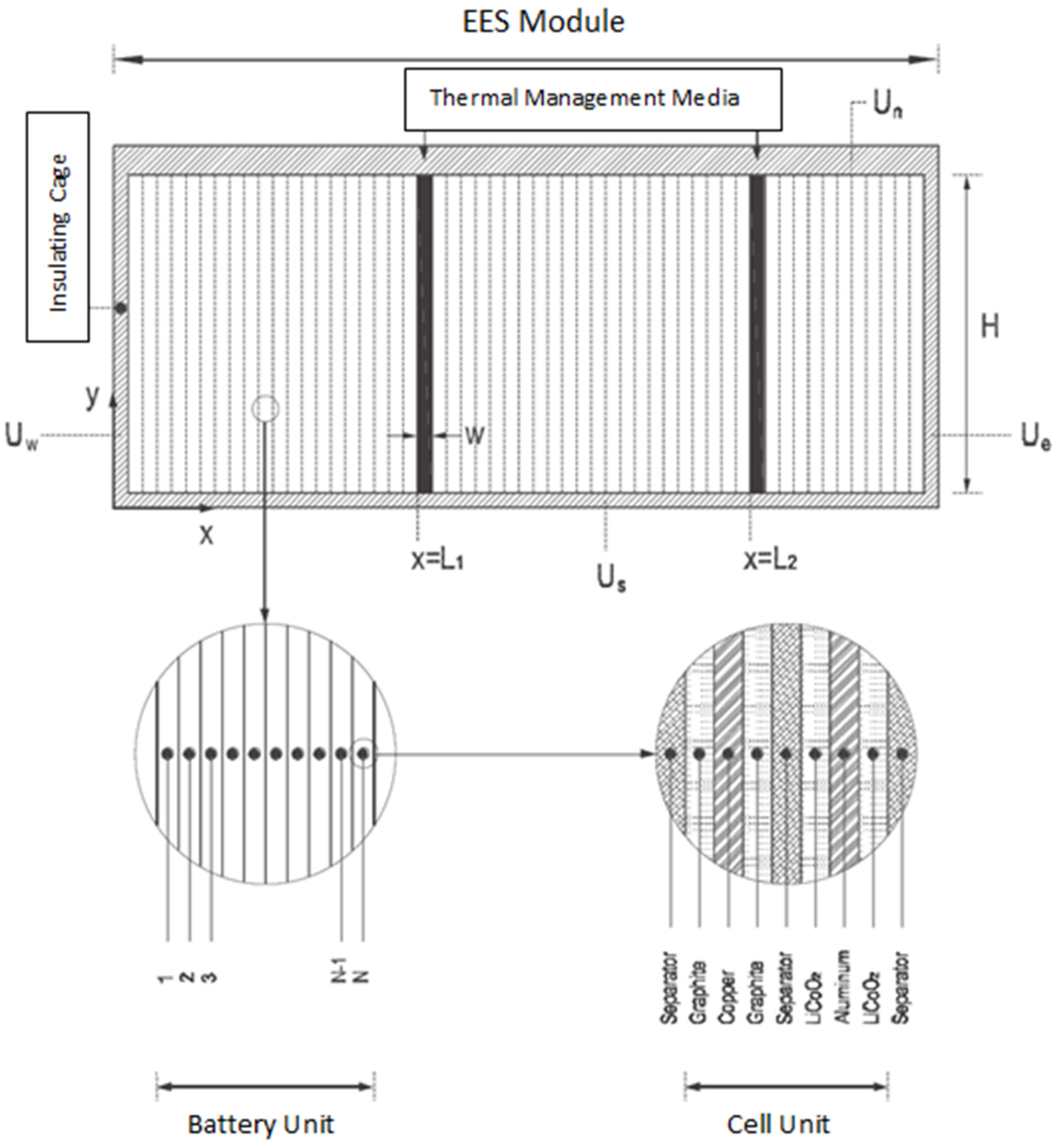
The structure of the model analysed is presented in Figure 2. The authors believed that because of the thin-film cell design, the thermal properties of different layers would greatly differ and would substantially influence the heat transfer behaviour within the battery. Thus a transient two-dimensional thermal model for the battery pack with heterogeneous thermal-physical properties for the various layers was developed.
Figure 2.
Schematic of Li-ion battery used in finite element analysis model [31].
Figure 2.
Schematic of Li-ion battery used in finite element analysis model [31].

The model was used to evaluate the efficacy of various thermal management methods for optimal operation of the battery pack. Boundary conditions were defined where applicable including at the boundary of the thermal management media and the external boundary of the battery pack. The whole computational domain (including the ESS container and thermal management channels) were divided into divisions of appropriate sizes and the governing equations were discretized for the various regions. Different mesh sizes were chosen for the various cell layers depending on their thermal diffusivity values and the expected temperature gradients. The implicit alternating-direction method was applied together with the boundary conditions, into finite difference forms which were then solved by the Thomas algorithm.
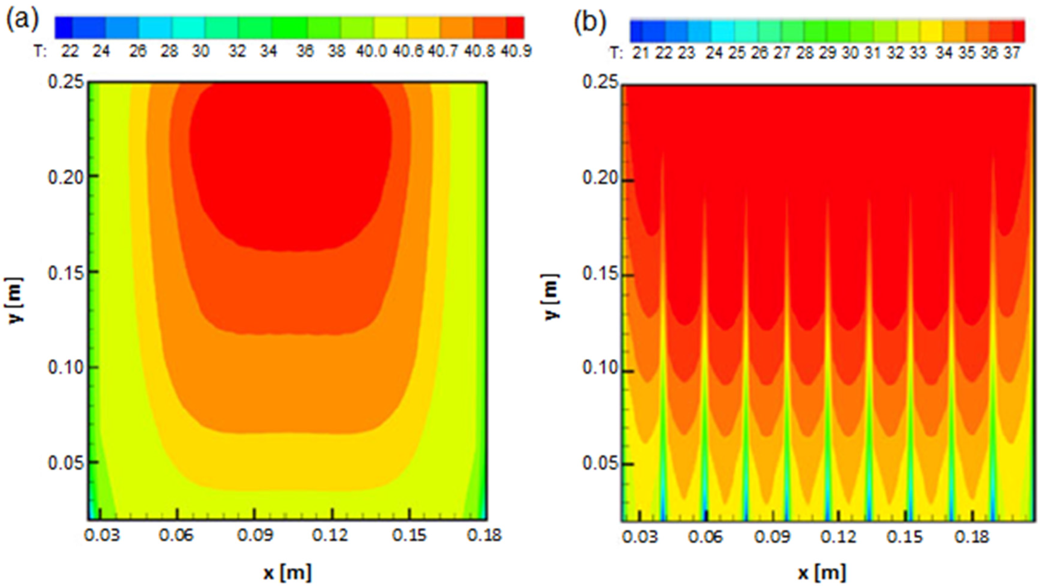
Figure 3 presents the simulated result of the temperature distribution in the ESS pack at the end of a 2C discharge cycle. The authors used their model to study the effect of the presence of thermal management media/channels on the temperature distribution of the ESS. These channels are illustrated in Figure 2. The model was also used to optimise the size and location of the channels to design an effective distributed cooling system that would improve the thermal performance of the ESS. The result of the higher performing optimised model is shown in Figure 3.
Figure 3.
Simulated temperature distribution results indicating the effectiveness of the optimised thermal management system; (a) Base model; (b) Optimised model [31].
Figure 3.
Simulated temperature distribution results indicating the effectiveness of the optimised thermal management system; (a) Base model; (b) Optimised model [31].

2.4. Numerical Thermal Behaviour Model with Analytical Validation
Xun, et al. [56] also used a numerical approach to study the effect of cooling channel design on the thermal behaviour of flat plate and cylindrical Li-ion ESS stacks during discharging processes. However in their study an analytical model was also developed to compare between the numerical and analytical results which was to be used as evidence to justify the models. The energy balance equation used in the analytical model for a battery unit in contact with the cooling channel is given as:
On the other hand for the other battery units the energy balance is given as:
whereby , and are the density, conductivity and specific capacity of the battery unit, A is the volume of each battery unit (m3), s is the surface area of the battery unit (m2), Ti is the volume averaged temperature of the battery unit i (°C), and t is the time instance (s). The convection coefficient h (W·m−2·°C−1) is given as:
whereby Nu is the Nusselt number, ka is the conductivity of air an L is the length (m) along the cooling channel. The initial conditions, material properties and heat generation variables were the same in the analytical and numerical approach. Both approaches used Equation (20) for the heat generation rate, Equations (23)–(25) for internal resistance and Equations (26)–(28) to model change in entropy. The analytical model can then be used to calculate the temperature in the ESS units at different time instances one by one. The results showed were reasonable agreement between the analytical and numerical models.
Xun, et al. [56] then applied the numerical model to investigate the effect of the size of the cooling channel. The goal of their investigation was to find the best balance between compactness and cooling energy efficiency of the ESS battery stacks. The study found that the volume ratio of cooling channel to battery needs to be higher than 0.014 when the inlet Reynolds number of cooling air is ≥2000 with a 2C discharging rate. In their comparison of cylindrical and flat plate design, the authors found that the general thermal behaviours are similar between the two designs however the cylindrical ESS stacks are generally less compact and more energy-efficient than the flat-plate ESS stacks.
In a later released work which was a continuation of this investigation, Xun and his team applied this numerical model to investigate the effectiveness of air, liquid and phase change materials (PCM) cooling mediums with regards to achieving a homogeneous temperature distribution within the desired range [16]. The findings of that study indicated that in normal ambient temperatures, liquid cooling displayed the best cooling effect whilst using PCMs for cooling achieved the most homogeneous temperature distribution with and acceptable cooling effect. PCM based thermal management systems have previously been shown to be effective with regards to uniform temperature distribution for ESS [57]. PCMs also perform well under very cold ambient temperatures for example in space applications [58]. The study highlighted the importance of choosing an appropriate cooling media and strategy in fast discharge conditions and low ambient temperatures. The results showed that for the ESS studied at a high 4C discharge under mild temperatures all three cooling medium investigated were not appropriate.
2.5. Finite Volume Thermal Model
In recent years finite volume numerical solutions like the Computational Fluid Dynamics CFD approach has developed to become a useful tool for science and engineering simulations. CFD has been applied for the thermal analysis of ESS [47,59,60,61,62,63,64,65,66]. Though computational intense, if used properly the approach can derive very accurate results.
He, et al. [60] developed a 2D CFD model for their investigation of the thermal management of multiple cells Li-ion modules. The model results were validated experimentally. The experimental layout consists of an open wind tunnel and a customised 4.6 Ah and 14.8 V battery module with multiple thermocouples to measure the cell temperatures. The experimental battery was tested for 0, 1, 2.5 and 5 m/s air flow velocities. The 2D CFD modelling and simulation was performed with ANSYS/FLUENT 14. The model was simulated for air flow velocities of 0.1 to 10 m/s corresponding to a Reynolds number of 356.9 to 356,900 for the model. This covers both the laminar flow regime and the fully developed turbulent flow regime. Heat conduction was assumed to occur only in the radial and azimuthal directions. For heat generation only Ohmic heating was considered. The authors believed that entropic heating is relatively small compared to Joule heating [60]. Thus for this model heat generation (Q) was given by:
where I is the charging or discharging current and R is the internal resistance as a function of cell temperature (T) given by:
The authors agree that this approximation of R is only applicable to the type of battery used in the model. Additionally it was also agreed that this approximation neglects the fact that the heat generation is a function of SOC. The authors believe this is justified due to the relatively small dependence of R on SOC. Besides that the approach used here also only considers the dependence of Q on SOC and neglects the effects the operating temperature has on Q. This was justified by the authors because the results obtained showed a small increase in cell temperature (< 5 °C). The authors accept that this model cannot be applied accurately for a wide range of ambient temperatures. The authors also investigated the effects of the wall/enclosure distance in the battery module. Overall this method showed good agreement with experimental data. However given the assumptions made in this approach, it is only valid for a fixed range of ideal ambient temperatures. The authors acknowledge this and in their ongoing work attempts to generalise the approach for applications where the temperature varies in a wide range.
2.6. Adaptive Thermal Model
Numerical modelling approaches can be applied concurrently with experimental calibration to form a hybrid approach of sort to model the thermal behaviour of ESS. It involves conducting experiments to collect data on the current (I), potential (E) and temperature (T) and then using this data to derive the equilibrium potential (Eeq) at each SOC and temperature.
The potential difference from the Eeq, the overpotential, is a substantial source of heat within the battery when multiplied to the applied current. For simplification the total overpotential (ηt) can be deduced to be caused by the sum of [44]: (i) the Ohmic losses in the battery (ηΩ); (ii) the diffusion and migration of Li ions through the electrolyte (ηm); (iii) the diffusion of Li-ion inside the electrodes (ηd); (iv) the charge transfer reactions at the electrode/electrolyte interface (ηct):
The Eeq of the cell is determined by plotting the discharge currents as a function of extracted charge, then using Polynomial Regression (PR) to extrapolate towards zero current. The PR method generates accurate quick results compared to other methods [9]. ηt is calculated by subtracting the Eeq from the corresponding experimentally measured cell potential (E) at each SOC. Once the overpotential heat generation is known the energy balance equation is solved with just this component of heat generation.
The other heat component, the change in entropy (ΔS) is derived from the change in Gibbs free energy (ΔG):
The equation can be rearranged and the partial derivatives of G, H and S taken to derive the equation for ΔS as:
After obtaining Eeq at various temperatures as a function of SOC, a finite difference approach is used in an unconstrained non-linear optimisation loop to estimate ∂Eeq/∂T in Equation (36) by minimising the error between the calculated and measured cell temperatures. The procedure in the approach is shown in Figure 4. All the relevant equations used in this analysis and referred to in Figure 4 are shown in Table 3.
This approach was applied by Rad, et al. [44]. The team designed an adaptive thermal modelling method for a Li-ion battery that used experimental data to derive the equilibrium potential subsequently the overpotential heat generation while using a numerical finite difference method to estimate the heat generation due to the change in entropy. This model was a continuing work from another previous adaptive thermal modelling investigation by one of the authors [67]. Previously some other models assumed the change in entropy was constant [68,69,70]. Rad, et al. [44] speculated that the SOC dependent change in entropy is an important heat source that is essential to include in order accurately predict the thermal behaviour of Li-ion ESS batteries under a wide range of operating conditions.
The research team experimentally investigated a 7.5 Ah Li-ion battery operating at ambient temperatures of 0, 20 and 40 °C. The experimental aspects involves cycling the ESS at a constant current constant voltage (CCCV) charging until the maximum cell potential 4.2 V is achieved, then relaxing the system for 3 h and finally discharging at constant current (CC until 2.7 V). Discharging was conducted at various C-rates. The temperature development of the cell was measured by the potential drop across thermistors connected to the battery tester via the auxiliary voltage input. In a climate control box, a water bath was used to control the ambient temperature. The team evaluated the thermal behaviour of the cell at the ambient temperatures investigated.
Figure 4.
Experimental and modelling procedure for predicting the thermal behaviour of Li-ion batteries using this adaptive approach [44].
Figure 4.
Experimental and modelling procedure for predicting the thermal behaviour of Li-ion batteries using this adaptive approach [44].
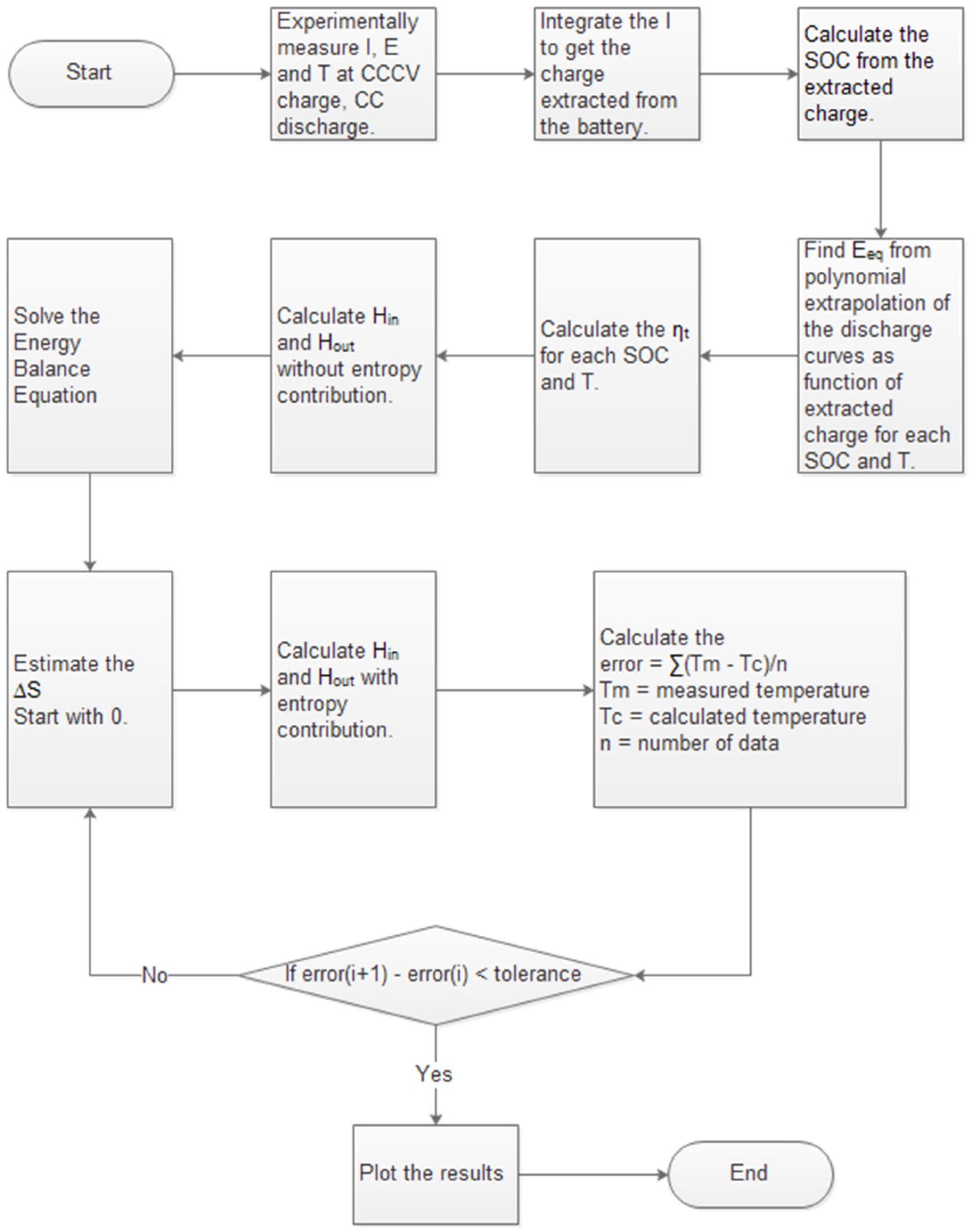
Table 3.
Thermodynamic formulas for the adaptive thermal model [44].
| Thermodynamic formulas | Variables |
|---|---|
| Energy Balance | m = mass of cell (g) CP = specific heat capacity (J·g−1·K−1) T = temperature (K) t = time (s) = all processes that generate heat (W) Qn = overpotential heat generation (W) ηt = total overpotential (V) Qs = entropic heat generation or consumption (W) = entropy change (J·mol−1·K−1) n = number of electrons transferred F = Faraday constant I = Current through individual electrodes (A) = Heat dissipate from cell (W) QC = Heat convection (W) QR = Heat radiation (W) h = convective heat transfer coefficient(W·m−2·K−1) A = surface area of cell (m2) Ta = ambient temperature (K) Nu = Nusselt number d = diameter of battery (m) k = air thermal conductivity (W·m−1·K−1) Ra = Rayleigh number Pr = Prandtl number σ = Stefan–Boltzmann constant (5.67 × 10⁻⁸ J·s−1·m−2·K−4) ε = emissivity factor of the battery surface material |
| Heat Generation | |
| Heat Dissipation |
The results indicated that while discharging down to 30% SOC, the entropic heat is endothermic and consumes energy from the environment consequently reducing the temperature. However below 30% of SOC, the discharge reaction becomes exothermic and the cell temperature increases. An interesting observation from this study is that in some of the initial stages of the charging process and the main part of discharging process, entropic heat generation, Qs is negative and counteracts the positive overpotential heat generation (Qn) even to the point of making the total heat generation negative in these regions. In these regions the battery consumes energy from the environment. Hence in spite of the positive Qn the temperature falls as the Qs is more prevalent. This entropic heat generation behaviour has also been shown in other newer analysis [28].
Another crucial finding of this study was that the ΔS contribution to heating is much more dominant at higher temperatures. The accuracy of the temperature profile in this study improved significantly by introducing ΔS. This was observed in all operating temperatures especially at elevated temperatures. Thus Rad, et al. [44] achieved a more accurate model by introducing ΔS as a function of SOC into the model. The advantage of this hybrid approach applied by Rad and his team is the high level of accuracy achievable if the experimental aspects are conducted properly. However this can also be a disadvantage given the high risk for errors due to the strong reliance on experimentally derived inputs for the model.
2.7. Other Numerical Thermal Model Applications
In recent years numerical modelling techniques are the prevalent approach for modelling thermal behaviour of ESS [71,72,73,74,75,76,77,78,79]. With the continuous increase in computational power and the better understanding of ESS materials, numerical approaches have the potential to produce very accurate results.
To meet the demand for efficient thermal management systems for ESS applications driven by the HEV and EV industries, researchers have experimented with various new methods to better manage heat removal. One of such novel methods is utilising multiple mini-channel liquid cooled cylinders (LCC) [80]. Zhao, et al. [80] used a numerical approach thermal model to optimise the design of the LCCs by fine tuning the channel quantity, mass flow rate, entrance size and flow direction to in the goal of maximising heat dissipation. In a similar study Zhao, et al. [81] used a numerical approach in optimising the ventilation type, gap spacing size, environmental and entrance air temperature, amount of single row cells and cell diameter on cooling effectiveness of several different battery modules.
In an older study Pesaran, et al. [82] investigated a passive thermal management system using strategically placed holes between the cells. The results concluded that an ESS pack with no air flow can reach hazardously high temperatures and strategically placed holes can substantially improve the thermal performance of the pack. This finding contributed to the design of many ESS available today. A finite element model was designed a few years later by one of the authors of the previous study to demonstrate the results of a module with holes obtaining a much lower maximum operating temperature and much lower core temperature difference [46].
Yu, et al. [83] explored a novel bi-directional air cooling mechanism to improve the temperature uniformity of the Li-ion ESS packs. A 3D thermal model for a CA180 ESS was designed using inputs from experimental measurement of thermal and physical properties of the materials. The electrical resistance and temperature coefficient (∂EOC/∂T) as a function of SOC were measured at a 1C discharge rate. Similar to other numerical approaches for convenience and adequate accuracy during transient analysis, the electrical resistance and temperature coefficient were fitted by 8th order and 6th order polynomials as a function of SOC. The numerical simulation results were compared directly with experimental data to validate the model. The comparison yielded a maximum error of the temperature between the simulation and experimental results of <1 °C. The results of this study indicated for the CA180 battery pack modelled at the test ambient temperature of 24 °C and 1C discharge rate, the temperature rise of was approximately 18 °C. The maximum temperature difference among the cells was >10 °C with an 8 °C temperature difference in the cell. The temperature rise was deemed to be detrimental to the lifetime of the ESS. The authors then modelled the proposed 2-directional air flow cooling mechanism with success in limiting the temperature difference in a cell to <5 °C. Park [84] also used a numerical modelling approach to optimise the design of air cooling system for Li-ion batteries used in HEVs.
Heat pipes have also been widely investigated as a thermal management mechanism for HEVs and EV Li-ion ESS [85,86,87,88,89]. Ye, et al. [85] used a numerical approach to study and optimise various design parameters for a heat pipe thermal management system including the number of pipes and the usage of heat fins/spreaders. The results of the transient simulation during ESS charging in the study had a 3.6% deviation from experimental testing at higher C rates (5C and 8C). The study found that a heat pipe thermal management system incorporated with an ESS can maintain safe operating temperatures for Li-ion batteries charged at a high C rate up to 8C.
3. Behavioural Models
Electrical Equivalent Circuit Thermal Models
Behavioural models use an electro-thermal approach in which electrical equivalent circuits are used to represent and model the development of the cell temperatures [90]. The thermal properties are represented by equivalent electrical quantities; temperature by voltage, heat flux by current, conductive resistance by conductive conductance, convective resistance by convective conductance and heat storage by capacitance. The aim of this thermal modelling approach is to build a direct correlation between the circuit elements and the electrochemical phenomena inside the cell.
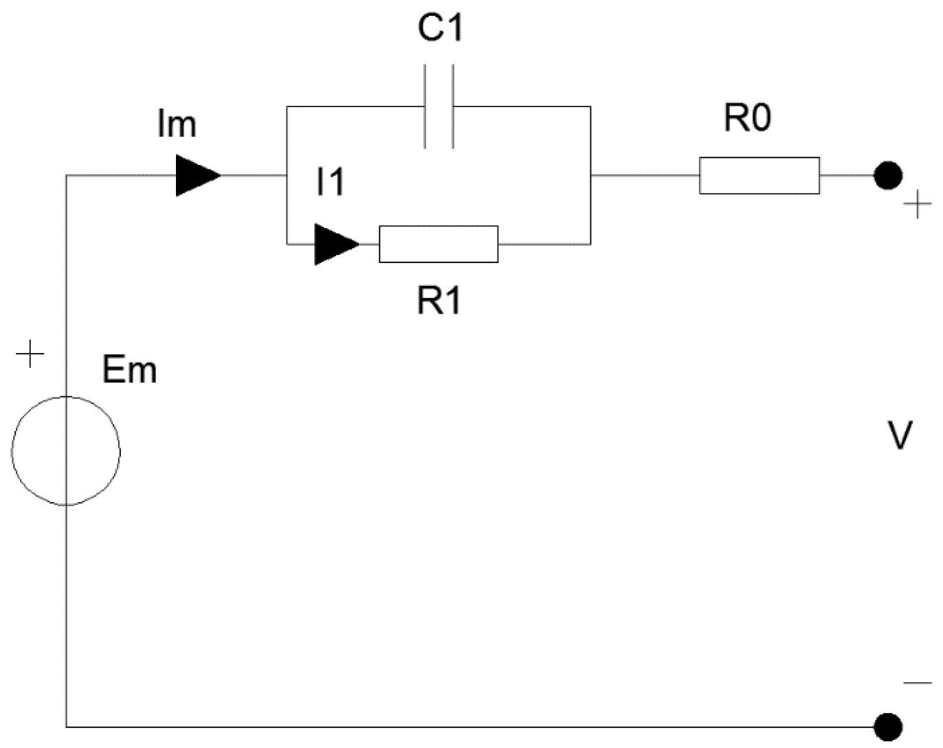
Based on the problem, the number of RC blocks typically ranges from one to two. Huria, et al. [91] claimed that more RC blocks increase computational effort without significantly improving model accuracy and a single RC block model is sufficient for problems of industrial relevance. An illustration of a single RC block equivalent circuit model containing a resistor (R1) and capacitor (C1) is shown in Figure 5. R0 represents the Ohmic internal resistance.
Figure 5.
Equivalent circuit model with one RC block.

The four independent components of the equivalent circuit modelling approach (Figure 5) vary depending on SOC and the assumed uniform average inner cell temperature. These components are normally experimentally derived via parameter estimation routines for various discharge experiments at various temperatures. The results were used to supply 2D lookup tables for these components. The SOC is given as:
where Im is the main branch current (A) and CQ is the cell capacity which is a function of current and temperature. The temperature is computed by solving the thermal equation of a homogeneous entity exchanging heat with the environment using:
whereby Cp is heat capacitance (J·m−3·K−1), T is the inner cell temperature (K), Ta is the ambient temperature (K), RT is the convection resistance (W·m−2·K−1) and Ps is the power dissipated inside the cell (W). Applying a Laplace transformation via a transform variable (s) on Equation (49) yields:
Given its simplicity and quick formulation the equivalent circuit thermal modelling approach is a common theoretical modelling technic for modelling electrochemical behaviour for ESS especially at a systems level [29,59,91,92,93,94,95,96,97,98]. This method was the ideal approach for the task of continuously monitoring the temperature distribution of an ESS for Xiao [29]. In this study an equivalent circuit model was used concurrently with a small number of physical sensors to estimate the temperature distribution throughout the remaining larger area of an ESS in real time. The equivalent circuit model in the study estimated the thermal distribution of the battery with negligible error in less than 15 s. For comparison a numerical model was also developed by the author. The numerical model had an error of 0.01 °C with a computational time of more than an hour while the equivalent circuit model had a larger error of 0.1 °C however the computational time was greatly reduced to less than 2 s.
4. Conclusions
This paper reviewed various theoretical models used to simulate the thermal behaviour of ESS to a high degree of accuracy. These models apply the concept of conservation of energy to solve for the temperature distribution in ESS. Knowing the temperature distribution in an ESS module is vital to ensure ideal operating temperatures as well as to minimise the temperature variations along the module—both prolonging the life of the ESS.
It has been shown in some of the researched papers that only considering the Ohmic heating and entropic heating/cooling as the two sources of heat generation is sufficient to produce precise results that agree with experimental results. Ohmic heating and entropic heating/cooling variables can be difficult to measure experimentally in all cases. There are estimation methods for these two variables formulated from previous experimental findings. Using these approximated values for both variables can produce sufficiently accurate results concurrently saving considerable time.
The papers researched through this review work indicate that in some instances using a simple approach like lumped capacitance and equivalent circuit thermal modelling approaches can produce accurate results. Lumped capacitance and equivalent circuit methods can be accurate enough for larger whole systems modelling saving much result processing and model setting-up time. Recently with the increase in computational power available to researchers, numerical methods have been one of the favoured approaches. If the numerical model including its thermo-physical properties, initial and boundary conditions have been set up well, numerical approaches can produce very accurate results. Besides that, numerical methods applied using modern software packages have the potential of generating useful visual representations of the model that can greatly assist designers in improving the aspects of the ESS like the design of the thermal management system.
In conclusion using theoretical modelling techniques can save substantial time and money in designing thermal management systems for ESS. Each model has its own advantages and disadvantages. It is often a trade-off between accuracy and complexity in modelling these systems. Time and computational resources are other factors that affect the functionality of the model. Refining the model with experimental data can produce much more accurate results where necessary. Table 4 summaries the advantages and disadvantages of each modelling approach discussed in this paper.
| Method | Advantages | Disadvantages | Recommended applications |
|---|---|---|---|
| Lumped Capacitance Thermal Approach | The main advantage of the lumped parameters method is that it is a simple method with a minimum set of data required to develop a satisfactory model to predict the thermal behaviour of Li-ion batteries [40]. Rather than setting all the characteristics and material types like required in a FEA or CFD analysis, the method “lumps” the characteristics together assuming the differences within each of these groups are not critical [99]. This makes it quick to design and run providing directionally correct estimates of the thermal performance of the ESS. The lumped capacitance approach is commonly adopted within other approaches like the equivalent circuit approach and some numerical approaches in order to simplify the complex problem. | The main disadvantage of this method is that there is a physical constraint to the possible applications due to Bi number limitations. Lumped parameters can only be used to model applications with Bi < 1. Bi is affected by large cell diameters and/or high heat transfer coefficients, limiting the application of the lumped parameters approach. This can be the case for many liquid cooling situations which are high h applications [100]. Additionally the results of Hallaj, et al. [40] indicated inaccuracy at a higher discharge rate of 1C-rate and abnormal operating conditions like extreme hot or cold operating temperatures. | System level modelling that requires fast processing time. The lumped parameters method is suitable for ESS thermal behaviour modelling under normal conditions of battery use for example under non-extreme operating temperatures [52]. |
| Numerical and Analytical Thermal Models | The main advantage of numerical methods like FEM and CFD is that these approaches are not very complex but it can yield a good level of accuracy. Applying heterogeneous thermo-physical properties can further improve the level of accuracy at the expense of computational time [31]. Computational time can be saved if the model is symmetrical. Adopting curved fitted thermal properties for Ri and ΔS is convenient but marginally compromises accuracy [31,44]. In most instances this is acceptable. | The disadvantage of this methodology is that it relies on accurate measurement or representation of the physical ESS model as well as a sound knowledge of the chemical and material compositions for an accurate representation. Also this method can be computational intensive depending on the 2D/3D model designed. This can limit the system model size based on a practical computational time. Numerical methods like FEA and CFD are inflexible and specific to the particular battery analysed. | Applications where a high level accuracy is required. Symmetrical models can benefit from a reduced computational domain hence processing time. Ideal for ESS cell level modelling. Numerical methods are an ideal tool when specific knowledge of the battery thermo-physical properties are known. Useful tool for system design optimisation for example as applied in [80,81,82,83,84,85]. |
| Equivalent Circuit Thermal Models | General behavioural models like equivalent circuit models are faster, more flexible and easier to formulate compared to numerical models. Minimal computational effort is required since in behavioural models the information regarding the different materials and associated thermo-physical properties within the cell are minimal [29]. | Similar to the lumped capacitance approach the disadvantage of the equivalent circuit approach is that it is potentially less accurate because the models calculates an average temperature for the entire chemistry within the battery unit [96]. | System level modelling that requires fast processing time. On-field or compact ESS battery thermal management systems [29]. The equivalent circuit approach is an ideal approach for systems level integration of ESS. The equivalent circuit approach is also useful for electro-thermal modelling in which electrical behaviour modelling is also required. |
It is important to note that the other vital part of ESS thermal management systems is the ability to monitor in situ the operating temperature of the ESS. The operating internal temperature of the ESS is critical, however it is very difficult to monitor in practice. It is usually not measureable in field. The overall aim is to have a combination of active monitoring of the surface temperature in combination with in situ modelling of the internal temperature and active control of the thermal management system. Research efforts are being directed towards this aim [101,102,103].
Nonetheless most of these models were designed with vehicular applications in mind. The operating conditions for stationary applications greatly vary to that of a moving vehicle. The rate of discharge, depth of discharge and even the cooling/heating media available can be different. Besides that all of these models were designed for normal operating temperatures. In most places, conditions that can be classified as abnormal operating conditions are common. As a next step the knowledge and experience from the modelling tools used in these approaches researched can be adapted to design thermal models for stationary ESS renewable energy storage applications operating at a wide range of operating temperatures.
Author Contributions
The authors contributed equally in conducting this review study.
Conflicts of Interest
The authors declare no conflict of interest.
References
- Wagner, R. Valve regulated lead-acid batteries for telecommunications and UPS applications. In Valve-Regulated Lead–Acid Batteries; Rand, D.J., Ed.; Elsevier B.V.: Oxford, UK, 2004; pp. 435–465. [Google Scholar]
- Percy, K. Ausnet Testing New Battery System to Curb Power Outages in Summer. Available online: http://www.abc.net.au/news/2015-01-07/ausnet-trialling-new-system-to-curb-power-outages-on-hot-days/6004454 (accessed on 30 May 2015).
- Pesaran, A.A. Battery thermal models for hybrid vehicle simulations. J. Power Sci. 2002, 110, 377–382. [Google Scholar] [CrossRef]
- Rothgang, S.; Rogge, M.; Becker, J.; Sauer, D.U. Battery design for successful electrification in public transport. Energies 2015, 8, 6715–6737. [Google Scholar] [CrossRef]
- Shabani, B.; Andrews, J. Standalone solar-hydrogen systems powering fire contingency networks. Int. J. Hydrogen Energy 2015, 40, 5509–5517. [Google Scholar] [CrossRef]
- Pesaran, A.; Vlahinos, A.; Stuart, T. Cooling and Preheating of Batteries in Hybrid Electric Vehicles; National Renewable Energy Laboratory (NREL): Colorado, CO, USA, 2003. [Google Scholar]
- Ji, Y.; Wang, Y. Heating strategies for Li-ion batteries operated from subzero temperatures. Electrochim. Acta 2013, 107, 664–674. [Google Scholar] [CrossRef]
- Szente-Varga, D.; Horvath, G.; Rencz, M. Thermal characterization and modelling of lithium-based batteries at low ambient temperature. In Proceedings of the 14th International Workshop on Thermal Inveatigation of ICs and Systems, 2008 (THERMINIC 2008), Rome, Italy, 24–26 September 2008.
- Bergveld, H.J.; Krujit, W.S.; Notten, P.H.L. Battery Management Systems-Design by Modelling, Philips Research Book Series Volume 1; Springer: Eindhoven, The Netherlands, 2002. [Google Scholar]
- Horie, H.; Abe, T.; Kinoshita, T.; Shimoida, Y. A study on an advanced lithium-ion battery system for EVs. World Electric Veh. J. 2008, 2, 25–31. [Google Scholar]
- Ye, Y.; Shi, Y.; Cai, N.; Lee, J.; He, X. Electro-thermal modeling and experimental validation for lithium ion battery. J. Power Sources 2012, 199, 227–238. [Google Scholar] [CrossRef]
- Vlahinos, A.; Pesaran, A. Energy Efficient Battery Heating in Cold Climates; SAE Technial Paper; SAE International: Warrendale, PA, USA, 2002; p. 10. [Google Scholar]
- Zhang, S.S.; Xu, K.; Jow, T.R. The low temperature performance of Li-ion batteries. J. Power Sources 2003, 115, 137–140. [Google Scholar] [CrossRef]
- Trinidad, F.; Gimeno, C.; Gutierrez, J.; Ruiz, R.; Sainz, J.; Valenciano, J. The VRLA modular wound design for 42 V mild hybrid systems. J. Power Sources 2003, 116, 128–140. [Google Scholar] [CrossRef]
- Yuksel, T.; Michalek, J. Evaluation of the Effects of Thermal Management on Battery Life in Plug-in Hybrid Electric Vehicles. Available online: http://www.cmu.edu/me/ddl/publications/2012-Battery-Congress-Yuksel-Michalek-Thermal-Mgmt.pdf (accessed on 14 July 2015).
- Xun, J.; Liu, R.; Chen, J.; Jiao, K.; Du, Q. Numerical investigation of thermal behaviors in lithium-ion battery stack discharge. Appl. Energy 2014, 132, 288–297. [Google Scholar]
- Kim, G.-H.; Gonder, J.; Lustbader, J.; Pesaran, A. Thermal management of batteries in advanced vehicles using phase-change materials. World Electric Veh. J. 2008, 2, 46–59. [Google Scholar]
- Zhu, C.; Li, X.; Song, L. Development of a theoretically based thermal model for lithium ion battery pack. J. Power Sources 2013, 223, 155–164. [Google Scholar] [CrossRef]
- Motloch, C.G.; Christophersen, J.P.; Belt, J.R.; Wright, R.B.; Hunt, G.L.; Sutula, R.A.; Duong, T.Q.; Tartamella, T.J.; Haskins, H.J.; Miller, T.J. High-Power Battery Testing Procedures and Analytical Methodologies for HEV’s; SAE International: Warrendale, PA, USA, 2002. [Google Scholar]
- Hunter, H. Extreme Temperatures Affect Electric Vehicle Driving Range, AAA Says. Available online: http://newsroom.aaa.com/2014/03/extreme-temperatures-affect-electric-vehicle-driving-range-aaa-says/ (accessed on 18 July 2015).
- Zhang, T.; Gao, C.; Gao, Q.; Wang, G.; Liu, M.; Guo, Y.; Xiao, C.; Yan, Y.Y. Status and development of electric vehicle integrated thermal management from BTM to HVAC. Appl. Thermal Eng. 2015, 88, 398–409. [Google Scholar] [CrossRef]
- Park, C.-W.; Jaura, A.K. Dynamic Thermal Model of Li-Ion Battery for Predictive Behavior in Hybrid and Fuel Cell Vehicles; SAE International: Warrendale, PA, USA, 2003. [Google Scholar]
- Mahamud, R.; Park, C. Reciprocating air flow for Li-ion battery thermal management to improve temperature uniformity. J. Power Sources 2011, 196, 5685–5696. [Google Scholar] [CrossRef]
- Taylor, J.N.A.C. Safety performance for phosphate based large format lithium-ion battery. In Proceedings of the 26th Annual International Telecommunications Energy Conference, 19–23 September 2004; pp. 146–148.
- Yamaki, J.; Ihara, M.; Okada, S. Improvement of thermal stability of lithium ion batteries by using methyl difluoroacetate as an electrolyte solvent. In Proceedings of the 25th Annual International Telecommunications Energy Conference, Yokohama, Japan, 23 October 2003; pp. 59–65.
- Ratnakumar, B.V.; Smart, M.C.; Halpert, G.; Kindler, A.; Frank, H.; DiStefano, S.; Ewell, R.; Surampudi, S. Lithium batteries on 2003 Mars Rover. In Proceedings of the 17th Annual Battery Conference on Applications and Advances, Long Beach, CA, USA, 15 January 2002; pp. 47–51.
- Semerie, J.P. Lithium-ion batteries for geosynchronous satellites. Qualification test results of the stentor battery. In Proceedings of the 35th Intersociety Energy Conversion Engineering Conference and Exhibit, Las Vegas, NV, USA, 24–28 July 2000; Volume 1, pp. 621–628.
- Amiribavandpour, P.; Shen, W.; Mu, D.; Kapoor, A. An improved theoretical electrochemical-thermal modelling of lithium-ion battery packs in electric vehicles. J. Power Sources 2015, 284, 328–338. [Google Scholar] [CrossRef]
- Xiao, Y. Model-based virtual thermal sensors for lithium-ion battery in EV applications. IEEE Trans. Ind. Electron. 2015, 62, 3112–3122. [Google Scholar] [CrossRef]
- Zhang, X.; Kong, X.; Li, G.; Jun, L. Thermodynamic assessment of active cooling/heating methods for lithium-ion batteries of electric vehicles in extreme conditions. Energy 2014, 64, 1092–1101. [Google Scholar] [CrossRef]
- Karimi, G.; Li, X. Thermal management of lithium-ion batteries for electric vehicles. Int. J. Energy Res. 2013, 37, 12–24. [Google Scholar] [CrossRef]
- Cooper, A. Development of a lead-acid battery for a hybrid electric vehicle. J. Power Sources 2004, 133, 116–125. [Google Scholar] [CrossRef]
- Cooper, A. Development of a high-performance lead–acid battery for new-generation vehicles. J. Power Sources 2005, 144, 385–394. [Google Scholar] [CrossRef]
- Karden, E.; Ploumen, S.; Fricke, B.; Miller, T.; Snyder, K. Energy storage devices for future hybrid electric vehicles. J. Power Sources 2007, 168, 2–11. [Google Scholar] [CrossRef]
- Lam, L.T.; Louey, R. Development of ultra-battery for hybrid-electric vehicle applications. J. Power Sources 2006, 158, 1140–1148. [Google Scholar] [CrossRef]
- Moseley, P.T.; Bonnet, B.; Copper, A.; Kellaway, M.J. Lead-acid battery chemistry adapted for hybrid electric vehicle duty. J. Power Sources 2007, 174, 49–53. [Google Scholar] [CrossRef]
- Pollet, B.; Staffell, I.; Shang, J. Current status of hybrid, battery and fuel cell electric vehicles: From electrochemistry to market prospects. Electrochem. Acta 2012, 84, 235–249. [Google Scholar] [CrossRef]
- Wu, B.; Yufit, V.; Marinescu, M.; Offer, G.J.M.-B.; Ricardo, F.; Brandon, N.P. Coupled thermal-electrochemical modelling of uneven heat generation in lithium-ion battery packs. J. Power Sources 2013, 243, 544–554. [Google Scholar] [CrossRef]
- Chen, K. Heat Generation Measurements of Prismatic Lithium Ion Batteries. Master’s Thesis, The University of Waterloo, Waterloo, ON, Canada, 2013. [Google Scholar]
- Hallaj, S.A.; Maleki, H.; Hong, J.S.; Selman, J.R. Thermal modeling and design considerations of lithium-ion batteries. J. Power Sources 1999, 83, 1–8. [Google Scholar] [CrossRef]
- Choi, S.S.; Lim, H.S. Factors that affect cycle-life and possible degradation mechanisms of a Li-ion cell based on LiCoO2. J. Power Sources 2002, 111, 130–136. [Google Scholar] [CrossRef]
- Cadex. Charging at High and Low Temperatures. Available online: http://batteryuniversity.com/learn/article/charging_at_high_and_low_temperatures (accessed on 25 May 2015).
- Plangklang, B.; Pornharuthai, P. Mathematical model and experiment of temperature effect on discharge of lead-acid battery for PV systems in tropical area. Energy Power Eng. 2013, 5, 43–49. [Google Scholar] [CrossRef]
- Rad, M.S.; Danilov, D.L.; Baghalha, M.; Kazemeini, M.; Notten, P.H.L. Adaptive thermal modeling of Li-ion batteries. Electrochim. Acta 2013, 102, 183–195. [Google Scholar]
- Rao, Z.; Wang, S. A review of power battery thermal energy management. Renew. Sustain. Energy Rev. 2011, 15, 4554–4571. [Google Scholar] [CrossRef]
- Pesaran, A. Tools for Designing Thermal Management of Batteries in Electric Drive Vehicles; National Renewable Energy Laboratory (NREL): Golden, CO, USA, 2013. [Google Scholar]
- Parsons, K.K. Design and Simulation of Passive Thermal Management System for Lithium-Ion Battery Packs on an Unmanned Ground Vehicle. Master’s Thesis, California Polytechnic State University, San Luis Obispo, CA, USA, 2012. [Google Scholar]
- Chen, S.; Wan, C.; Wang, Y. Thermal analysis of lithium-ion batteries. J. Power Sources 2005, 140, 111–124. [Google Scholar] [CrossRef]
- DeWitt, I.; Bergman, L. Fundamentals of Heat and Mass Transfer, 6th ed.; John Wiley & Sons: Hoboken, NJ, USA, 2007. [Google Scholar]
- Kim, Y.; Siegel, J.B.; Stefanopoulou, A.G. A computationally efficient thermal model of cylindrical battery cells for the estimation of radially distributed temperatures. In Proceedings of the 2013 American Control Conference (ACC), Washington, DC, USA, 17–19 June 2013.
- Ismail, N.H.F.; Toha, S.F.; Mohd Azubir, N.A.; Ishak, N.H.M.; Hassan, M.K.; Ibrahim, B.S. Simplified heat generation model for lithium ion battery used in electric vehicle. In Proceedings of the 5th International Conference on Mechatronics (ICOM’13), Kuala Lumpur, Malaysia, 2–4 July 2013.
- Maleki, H.; Hong, J.S.; Hallaj, S.A.; Selman, J.R. The Electrochemical Society and International Society of Electrochemistry Meeting Abstracts; The Electrochemical Society and International Society of Electrochemistry: Paris, France, 1997. [Google Scholar]
- Hong, J.S.; Maleki, H.; Al Hallaj, S.; Redley, L.; Selman, J.R. Electrochemical-calorimetric studies of lithium-ion cells. Electrochem. Soc. 1998, 145, 1489–1501. [Google Scholar] [CrossRef]
- Inui, Y.; Kobayashi, Y.; Watanabe, Y.; Watase, Y.; Kitamura, Y. Simulation of temperature distribution in cylindrical and prismatic lithium ion secondary batteries. Energy Convers. Manag. 2007, 48, 2103–2109. [Google Scholar] [CrossRef]
- Onda, K.; Ohshima, T.; Nakayama, M.; Fukuda, K.; Araki, T. Thermal behavior of small lithium-ion battery during rapid charge and discharge cycles. J. Power Sources 2006, 158, 535–542. [Google Scholar] [CrossRef]
- Xun, J.; Liu, R.; Jiao, K. Numerical and analytical modeling of lithium ion battery thermal behaviors with different cooling designs. J. Power Sources 2013, 223, 47–61. [Google Scholar] [CrossRef]
- Ling, Z.; Chen, J.; Fang, X.; Zhang, Z.X.; Tao, X.; Gao, X.; Wang, S. Experimental and numerical investigation of the application of phase change materials in a simulative power batteries thermal management system. Appl. Energy 2014, 121, 104–113. [Google Scholar] [CrossRef]
- Al-Hallaj, S.; Selman, J.R. Thermal modeling of secondary lithium batteries for electric vehicle/hybrid electric vehicle applications. J. Power Sources 2002, 110, 341–348. [Google Scholar] [CrossRef]
- Iraola, U.; Aizpuru, I.; Canales, J.M.; Etxeberria, A. Methodology for thermal modelling of lithium-ion batteries. In Proceedings of the IECON 2013—39th Annual Conference of the IEEE Industrial Electronics Society, Vienna, Austria, 10–13 November 2013.
- He, F.; Li, X.; Ma, L. Combined experimental and numerical study of thermal management of battery module consisting of multiple Li-ion cells. Int. J. Heat Mass Transf. 2014, 72, 622–629. [Google Scholar] [CrossRef]
- Hu, X. Advanced numerical simulation helps accelerate the development of safe, long-lasting and cost-effective batteries for electric vehicles. In Battery Thermal Management in Electric Vehicles; ANSYS Incorporated: Canonsburg, PA, USA, 2015. [Google Scholar]
- Javani, N.; Dincer, I.; Naterer, G.F.; Rohrauer, G.L. Modeling of passive thermal management for electric vehicle battery packs with PCM between cells. Appl. Thermal Eng. 2014, 73, 307–316. [Google Scholar] [CrossRef]
- Wang, T.; Tseng, K.J.; Zhao, J.; Wei, Z. Thermal investigation of lithium-ion battery module with different cell arrangement structures and forced air-cooling strategies. Appl. Energy 2014, 134, 229–238. [Google Scholar] [CrossRef]
- Xu, X.M.; He, R. Research on the heat dissipation performance of battery pack based on forced air cooling. J. Power Sci. 2013, 240, 33–41. [Google Scholar] [CrossRef]
- Chacko, S.; Chung, Y.M. Thermal modelling of Li-ion polymer battery for electric vehicle drive cycles. J. Power Sources 2012, 213, 296–303. [Google Scholar] [CrossRef]
- Fan, L.; Khodadadi, J.M.; Pesaran, A.A. A parametric study on thermal management of an air-cooled lithium-ion battery module for plug-in hybrid electric vehicles. J. Power Sources 2013, 238, 301–312. [Google Scholar] [CrossRef]
- Danilov, D.L.; Ledovskikh, A.; Notten, P.H.L. Adaptive thermal modeling of rechargeable batteries for advanced automotive battery management systems. In Prcoeedings of the 8th International Automotive Congress, Eindhoven, The Netherlands, 16–17 March 2011; p. 50.
- Chen, Y.; Evans, J.W. Thermal analysis of lithium-ion batteries. J. Electrochem. Soc. 1996, 143, 2708–2712. [Google Scholar] [CrossRef]
- Chen, Y.; Evans, J.W. Three-dimensional thermal modeling of lithium-polymer batteries under galvanostatic discharge and dynamic power profile. J. Electrochem. Soc. 1994, 141, 2947–2955. [Google Scholar] [CrossRef]
- Chen, Y.; Evans, J.W. Heat transfer phenomena in lithium/polymer-electrolyte batteries for electric vehicle applications. J. Electrochem. Soc. 1993, 140, 1833–1838. [Google Scholar] [CrossRef]
- Guo, G.; Long, B.; Cheng, B.; Zhou, S.; Xu, P.; Cao, B. Three-dimensional thermal finite element modeling of lithium-ion battery in thermal abuse application. J. Power Sources 2015, 195, 2393–2398. [Google Scholar] [CrossRef]
- Jeon, D.H.; Baek, S.M. Thermal modeling of cylindrical lithium ion battery during discharge cycle. Energy Convers. Manag. 2011, 52, 2973–2981. [Google Scholar] [CrossRef]
- Karimi, G.; Dehghan, A.R. Thermal analysis of high-power lithium-ion battery packs using flow network approach. Int. J. Energy Res. 2014, 38, 1793–1811. [Google Scholar] [CrossRef]
- Sun, H.; Wang, X.; Tossan, B.; Dixon, R. Three-dimensional thermal modeling of a lithium-ion battery pack. J. Power Sources 2012, 206, 349–356. [Google Scholar] [CrossRef]
- Jeon, D.H. Numerical modeling of lithium ion battery for predicting thermal behavior in a cylindrical cell. Curr. Appl. Phys. 2014, 14, 196–205. [Google Scholar] [CrossRef]
- Liu, Y.; Yang, S.; Guo, B.; Deng, C. Numerical analysis and design of thermal management system for lithium ion battery pack using thermoelectric coolers. Adv. Mech. Eng. 2014, 6, 1–8. [Google Scholar] [CrossRef]
- Xu, M.; Zhang, Z.; Wang, X.; Yang, L. A pseudo three-dimensional electrochemicalethermal model of a prismatic LiFePO4 battery during discharge process. Energy 2015, 80, 303–317. [Google Scholar] [CrossRef]
- Xu, M.; Zhang, Z.; Wang, X.; Jia, L.; Yang, L. Two-dimensional electrochemicalethermal coupled modeling of cylindrical LiFePO4 batteries. J. Power Sources 2014, 256, 233–243. [Google Scholar] [CrossRef]
- Tong, W.; Somasundaram, K.; Birgersson, E.; Mujumdar, A.S.; Yap, C. Numerical investigation of water cooling for a lithium-ion bipolar battery pack. Int. J. Thermal Sci. 2015, 94, 259–269. [Google Scholar] [CrossRef]
- Zhao, J.; Rao, Z.; Li, Y. Thermal performance of mini-channel liquid cooled cylinder based battery thermal management for cylindrical lithium-ion power battery. Energy Convers. Manag. 2015, 103, 157–165. [Google Scholar] [CrossRef]
- Zhao, J.; Rao, Z.; Huo, Y.; Liu, X.; Li, Y. Thermal management of cylindrical power battery module for extending the life of new energy electric vehicles. Appl. Thermal Eng. 2015, 85, 33–43. [Google Scholar] [CrossRef]
- Pesaran, A.; Vlahinos, A.; Burch, S. Thermal Performance of EV and HEV Battery Modules and Packs; National Renewable Energy Laboratory (NREL): Golden, CO, USA, 1997. [Google Scholar]
- Yu, K.; Yang, X.; Cheng, Y.; Li, C. Thermal analysis and two-directional air flow thermal management for lithium-ion battery pack. J. Power Sources 2014, 270, 193–200. [Google Scholar] [CrossRef]
- Park, H. A design of air flow configuration for cooling lithium ion battery in hybrid electric vehicles. J. Power Sources 2013, 239, 30–36. [Google Scholar] [CrossRef]
- Ye, Y.; Saw, L.H.; Shi, Y.; Tay, A.A.O. Numerical analyses on optimizing a heat pipe thermal management system for lithium-ion batteries during fast charging. Appl. Thermal Eng. 2015, 86, 281–291. [Google Scholar] [CrossRef]
- Tran, T.-H.; Harmand, S.; Sahut, B. Experimental investigation on heat pipe cooling for hybrid electric vehicle and electric vehicle lithium-ion battery. J. Power Sources 2014, 265, 262–272. [Google Scholar] [CrossRef]
- Rao, Z.; Wang, S.; Wu, M.; Lin, Z.; Li, F. Experimental investigation on thermal management of electric vehicle battery with heat pipe. Energy Convers. Manag. 2013, 65, 92–97. [Google Scholar] [CrossRef]
- Prasher, R.S. A simplified conduction based modeling scheme for design sensitivity study of thermal solution utilizing heat pipe and vapor chamber technology. J. Electron. Packag. 2003, 126, 378–385. [Google Scholar] [CrossRef]
- Greco, A.; Cao, D.; Jiang, X.; Yang, H. A theoretical and computational study of lithium-ion battery thermal management for electric vehicles using heat pipes. J. Power Sources 2014, 257, 344–355. [Google Scholar] [CrossRef]
- Forgez, C.; Do, D.V.; Friedrich, G.; Morcrette, M.; Delacourt, C. Thermal modeling of a cylindrical LiFePO4/graphite lithium-ion battery. J. Power Sources 2010, 195, 2961–2968. [Google Scholar] [CrossRef]
- Huria, T.; Massimo, C.; Jackey, R.; Gazzarri, J. High fidelity electrical model with thermal dependence for characterization and simulation of high power lithium battery cells. In Proceedings of the 2012 IEEE International Electric Vehicle Conference (IEVC), Greenville, SC, USA, 4–8 March 2012; pp. 1–8.
- Jackey, R. A Simple, Effective Lead-Acid Battery Modeling Process for Electrical System Component Selection; SAE Paper; SAE International: Warrendale, PA, USA, 2007; pp. 1–9. [Google Scholar]
- Murashko, K.; Pyrhonen, J.; Laurila, L. Three-dimensional thermal model of a lithium ion battery for hybrid mobile working machines: Determination of the model parameters in a pouch cell. IEEE Trans. Energy Convers. 2013, 28, 335–343. [Google Scholar] [CrossRef]
- Erdinc, O.; Vural, B.; Uzunoglu, M. A dynamic lithium-ion battery model considering the effects of temperature and capacity fading. In Proceedings of the International Conference on Clean Electrical Power, Capri, Italy, 9–11 June 2009; pp. 383–386.
- Damay, N.; Forgez, C.; Bichat, M.-P.; Friedrich, G. Thermal modeling of large prismatic LiFePO4/graphite battery. Coupled thermal and heat generation models for characterization and simulation. J. Power Sources 2015, 283, 37–45. [Google Scholar] [CrossRef]
- Fathian, K.; Hassanipour, F.; Gans, N.R. Virtual thermal sensing and control of heat distribution using state estimation. In Proceedings of the ASME 2012 International Mechanical Engineering Congress and Exposition, Houston, TX, USA, 9–15 November 2012; pp. 1725–1738.
- L.H, S.; Ye, Y.; Tay, A.A.O. Electro-thermal characterization of lithium iron phosphate cell with equivalent circuit modeling. Energy Convers. Manag. 2014, 87, 367–377. [Google Scholar]
- Saw, L.H.; Ye, Y.; Tay, A.A.O. Electrochemical-thermal analysis of 18650 lithium iron phosphate cell. Energy Convers. Manag. 2013, 75, 162–167. [Google Scholar] [CrossRef]
- Warner, J. Chapter 6—Computer-aided design and analysis. In The Handbook of Lithium-Ion Battery Pack Design; Elsevier Science: Midland, MI, USA, 2015; pp. 59–63. [Google Scholar]
- Mahamud, R.; Park, C. Spatial-resolution, lumped-capacitance thermal model for cylindrical Li-ion batteries under high biot number conditions. Appl. Math. Model. 2013, 37, 2787–2801. [Google Scholar] [CrossRef]
- Lin, X.; Stefanopoulou, A.G.; Fu, H.; Perez, H.E.; Siegel, J.B.; Ding, Y.; Castanier, M.P. Parameterization and observability analysis of scalable battery clusters for onboard thermal management. Oil Gas Sci. Technol. 2013, 68, 165–178. [Google Scholar] [CrossRef]
- Lin, X.; Stefanopoulou, A.G.; Perez, H.E.; Siegel, J.B.; Li, Y.; Anderson, R.D. Quadruple adaptive observer of the core temperature in cylindrical Li-ion batteries and their health monitoring. In Proceedings of the 2012 American Control Conference, Fairmont Queen Elizabeth, Montréal, QC, Canada, 27–29 June 2012.
- Lin, X.; Perez, H.E.; Siegel, J.B.; Stefanopoulou, A.G. Online parameterization of lumped thermal dynamics in cylindrical lithium ion batteries for core temperature estimation and health monitoring. IEEE Trans. Control Syst. 2013, 21, 1745–1755. [Google Scholar]
© 2015 by the authors; licensee MDPI, Basel, Switzerland. This article is an open access article distributed under the terms and conditions of the Creative Commons Attribution license (http://creativecommons.org/licenses/by/4.0/).
Share and Cite
MDPI and ACS Style
Shabani, B.; Biju, M. Theoretical Modelling Methods for Thermal Management of Batteries. Energies 2015, 8, 10153-10177. https://doi.org/10.3390/en80910153
AMA Style
Shabani B, Biju M. Theoretical Modelling Methods for Thermal Management of Batteries. Energies. 2015; 8(9):10153-10177. https://doi.org/10.3390/en80910153
Chicago/Turabian StyleShabani, Bahman, and Manu Biju. 2015. "Theoretical Modelling Methods for Thermal Management of Batteries" Energies 8, no. 9: 10153-10177. https://doi.org/10.3390/en80910153