Article

Synergetic Effect between Lighting Efficiency Enhancement and Building Energy Reduction Using Alternative Thermal Operating System of Indoor LED Lighting

1
Energy Saving Laboratory, Korea Institute of Energy Research, 152 Gajeong-ro, Yuseong-gu, Daejeon 305-343, Korea
2
Department of Architectural Engineering, Yonsei University, 50 Yonsei-ro, Seodaemun-gu, Seoul 120-749, Korea
3
Energy ICT Laboratory, Korea Institute of Energy Research, 152 Gajeong-ro, Yuseong-gu, Daejeon 305-343, Korea
*
Author to whom correspondence should be addressed.
Energies 2015, 8(8), 8736-8748; https://doi.org/10.3390/en8088736
Submission received: 30 June 2015 / Revised: 6 August 2015 / Accepted: 7 August 2015 / Published: 17 August 2015
(This article belongs to the Special Issue Energy Conservation in Infrastructures)

Abstract

:
We investigated the synergetic effect between light-emitting diode (LED) lighting efficiency and building energy savings in heating and cooling using an alternative thermal operating system (ATOS) of indoor LED lighting integrated with the ventilation system of a building as an active cooling device. The heat generated from LED lighting and the indoor lighting illuminance were experimentally determined. The indoor heat gains in cooling and heating periods were determined using measurement data; the annual energy savings of an office building in heating and cooling were calculated through simulation. The LED lighting illuminance increased by approximately 40% and the lighting contribution for indoor heat gain was 7.8% in summer, while 69.8% in winter with the ATOS. Consequently, the annual total energy use of the office building could be reduced by 5.9%; the energy use in cooling and heating was reduced by 18.4% and 3.3%, respectively.

Graphical Abstract

1. Introduction

The recent increasing trend in global energy consumption and carbon dioxide emissions has led to increased interest in energy-related technologies in various fields [1,2,3]. Because the total energy consumption in buildings accounts for nearly 40% of the primary energy use in many countries, a number of studies on energy-saving technologies for buildings have been conducted with a focus on the thermal performance of envelopes, efficiency enhancement of lighting and air-conditioning facilities, and renewable energy applications [4,5,6,7]. In order to reduce the lighting energy in buildings, high-efficiency light-emitting diode (LED) lamps and light-dimming control using daylight harvesting have been developed [8,9,10,11].
In general, high-efficiency LEDs should be developed with a focus on the optimal chip design, patterned sapphire substrate, photonic crystal structures, etc. at a chip level to increase the light extraction efficiency [12,13]. Furthermore, in high-power LEDs, nearly 25% of the input power is converted to light, while the rest is dissipated in the form of heat, causing the light extraction efficiency, emission intensity, and lifetime to decrease [14,15,16,17]. Therefore, at a system level, the thermal management of high-power LEDs is an essential research area and development involving printed circuit boards for a direct thermal path to the heat sink and an active cooling method with a fan that spreads the heat to the ambient environment [18,19,20].
The waste heat from the heat sink of LED lighting in an office building has a negative effect on the cooling energy demand during the cooling period. This waste heat, which is beneficial to the heating energy demand during the heating period if it stays within the ceiling, is lost to the external environment when the outdoor temperature decreases [21,22]. To solve these issues, Ahn et al. [23] suggested a conceptual design of a movable heat sink of LED lighting in an office building that rejects heat to the outdoors during the cooling period and fully retains the heat indoors during the heating period. In that research, the heating and cooling energies of a virtual building with fluorescent lighting and heat-controlled LED lighting were compared, and a total energy reduction of 9.27% was obtained in the simulation result. Although a lighting heat recovery method using conventional fluorescent lighting in buildings has been proposed, it was difficult to enhance the efficiency of heat recovery because 37% of the input power to the fluorescent lighting is transferred in the form of radiant heat, which is difficult to move to another space. However, LED lighting emits 25% visible light and 75% convective heat, rather than radiant heat; therefore, most of the LED-generated heat can be reused and removed by transporting to another space [24].
In the present study, we propose an alternative thermal operating system (ATOS) of indoor LED lighting with a seasonal strategy and investigate the synergetic effect of LED lighting efficiency and building energy reduction through experiments. To confirm the effectiveness of the proposed method, we simulated a commercial building and calculated the annual energy savings in heating and cooling.

2. Methodology

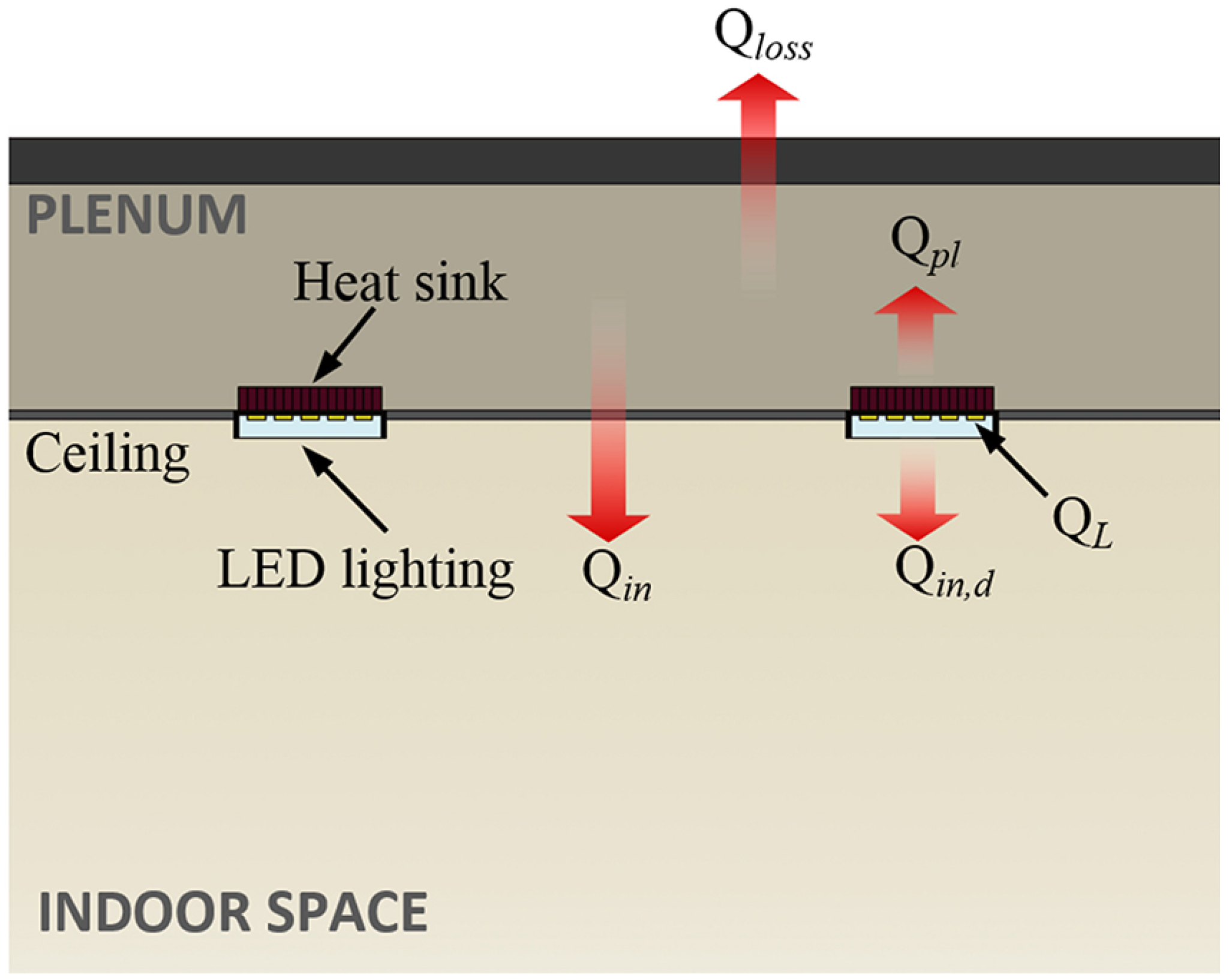
2.1. Theoretical Background of Indoor Heat Gain from Lighting

In an office building, heat from LED lighting can be generally transferred into a plenum area in the form of convective heat through a heat sink connected to the LED lighting, as shown in Figure 1. First, this heat increases the plenum air temperature. Second, a part of the heat is transferred to the indoor space, and the rest is lost to the outdoors [25]. The equation of heat transfer from lighting to indoor space is as follows:
Q L = Q i n , d + ( Q p l + Q i n + Q l o s s ) η s
where QL is the LED lighting heat; Qin,d is the heat directly transferred from the LED chip to the indoor space; Qpl is the heat transferred from the heat sink to the plenum area; Qin is the heat transferred from the plenum to indoor space; Qloss is the heat lost from the plenum to the outdoors, and ηs is the heat transfer efficiency from the LED chip to the heat sink; Qin,d is negligible because the area of the LED chip is quite low, even though the heat flux is considerable. Therefore, the indoor heat gain Qin at steady state is expressed as:
Q i n η s Q L ( Q p l + Q l o s s )
In Equation (2), because QL is determined by efficiency of the LED lighting appliance and Qpl has a constant value at the steady state; Qloss can be a considerable factor in determining the lighting heat transferred from the plenum to the indoor space. In summer with the high outdoor temperature and solar radiation; Qloss is not zero; the indoor heat gain from the outdoor environment could even be increased to have a negative effect on the cooling load. Furthermore, in winter, there is little advantage on the heating load because Qloss increases owing to the low temperature of the outdoor atmosphere.
Figure 1. Schematic view of the indoor heat gain from LED lighting.
Energies 08 08736 g001

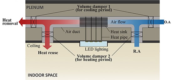
2.2. Alternative Thermal Operating System of Indoor LED lighting

In order to solve the problem of heat loss denoted by Qloss, we suggest an alternative thermal operating system (ATOS) that consists of an ATOS module in conjunction with a heating, ventilation, and air conditioning (HVAC) duct placed in the plenum area of the building. In this system, the heat from the LED chip is transferred to the heat sink via a connected heat pipe, and this heat is convectively transferred to the outdoors or indoor space through air flow according to a seasonal operating strategy. In the cooling period, most of the heat from the heat sink can be emitted to the outdoors through the HVAC duct with the operation of one volume damper (VD-1). Thus, it is possible to reduce the lighting heat gain to the indoor space and cooling load in the building. In the heating period, the convective heat is returned to the indoor space with the operation of another volume damper (VD-2), reducing the heating load.
In the ATOS module for lighting heat exchange, a chip-on-board (COB) packaged LED chip was selected for enhancing the heat-transfer efficiency because of the high heat flux in a small area. The heat pipe attached to the back side of the LED chip is a type of loop heat pipe (LHP) consisting of copper with water as the working fluid. The aluminum heat sink connected with the heat pipe cools the device by dissipating heat to the ambient environment. The operating scheme of the ATOS with a building HVAC duct is schematically shown in Figure 2a, and Figure 2b shows the ATOS module designed to implement this system.
Figure 2. (a) Operating scheme of the ATOS with a building HVAC duct and (b) A photograph of the ATOS module.
Energies 08 08736 g002

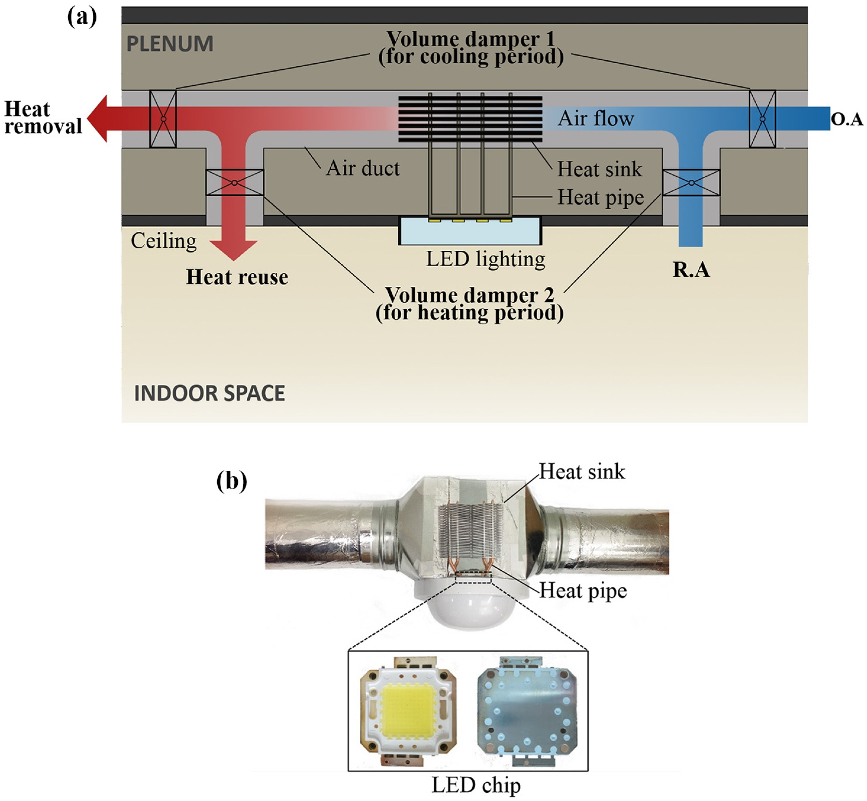
2.3. Experimental Setup

In order to verify the enhancement in LED lighting efficiency and the indoor thermal effect of this system, an experiment was conducted, as shown in Figure 3a, in a mock-up chamber located in Daejeon, South Korea, at coordinates of 36.22°N and 127.22°E. The mock-up chamber was designed to measure the indoor thermal conditions and illuminance of lighting. The indoor space was 3.9 m wide, 2.5 m long, and 2.1 m high, and the plenum was 0.5 m high with the same width and length. On the ceiling, which consisted of plasterboard (10 mm), two 60-W LED lights with an ATOS module (LM-1) and two conventional 60-W LED lights (LM-2) were installed. The input power to the 60-W LED lights was supplied by a DC power supply of 36 V and 1.7 A. The luminous flux of the LED lights was 5800 lm with a color temperature of 5700 K, and luminous efficiency greater than 95 lm/W. The average interior illuminance at the task plane (0.8 m above the floor) [26] was 630 lx, ranging from 480 lx to 1080 lx, and the uniformity ratio was 0.76. As a bronze-coated glazing that has a low visible reflectance of 0.05 [27] was installed on the north wall (left side) while all the interior walls were painted in white color of reflectance 0.65, the horizontal illuminance distribution was slightly non-uniform towards each side. T-type thermocouples with an error range of ±0.5 °C were applied as a thermal sensor; they were placed at 25 points for the indoor air temperature, 15 points for the plenum air temperature, 2 points for the front and rear air temperature of the heat sink, one point for the heat sink surface temperature, one point for the air temperature of the heat exchange module and one point for the outdoor air temperature. There was no mechanical heating or cooling for indoor air conditioning; therefore, the indoor thermal condition was only affected by the outdoor weather condition and LED lighting heat.
The experiment was conducted from 20 to 23 September 2014, and 8–11 January 2015, during summer and winter. The outdoor environmental parameters are listed in Table 1. The temperatures of the indoor space, plenum, heat sink, and lighting illuminance were monitored in 1-min intervals. The measurement points for temperature and illuminance are shown in Figure 3b, and the interior illuminance distribution at the task plane is described in Figure 3c.
Table 1. Outdoor enviromental parameters for the experiment.
Measurement ItemsSummerWinter
Outdoor air temperature15.2 °C to 27.4 °C−5.5 °C to 3.0 °C
Mean relative humidity63.8%69.8%
Mean air velocity1.3 m/s0.9 m/s
Figure 3. (a) Photograph of the mock-up chamber; (b) schematic view of the measurement points for temperature and illuminance; and (c) interior illuminance distribution at the task level.
Energies 08 08736 g003

3. Results and Discussion

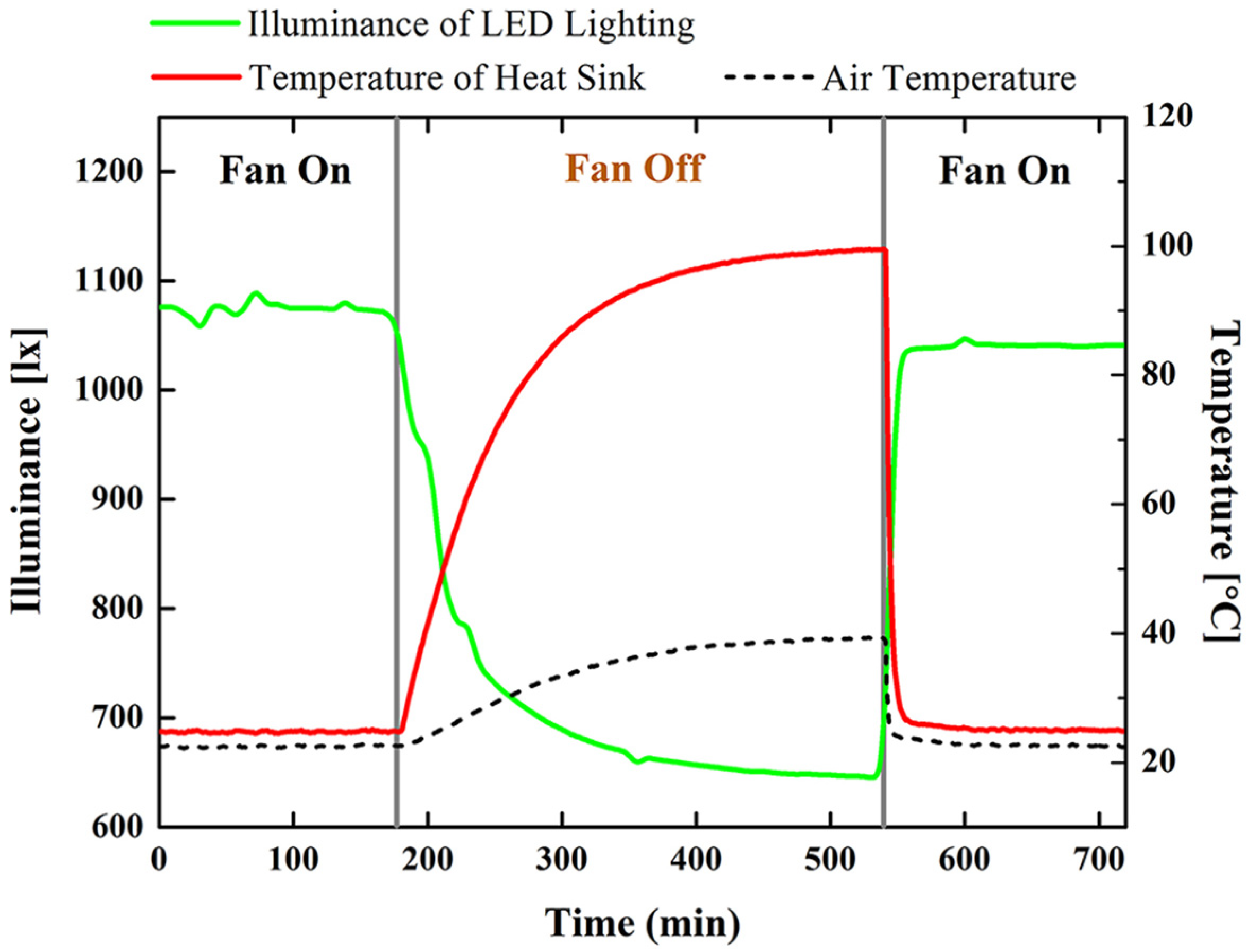
3.1. Illuminance and Temperature Variation under Active Cooling Control

Figure 4 shows the variation in the LED lighting illuminance, air temperature of the ATOS module, and temperature of the heat sink according to the operation of the HVAC fan as an active cooling device. The illuminance of the LED lighting is clearly reduced by 39.8% (from 1072 lx to 645 lx) when the HVAC fan is interrupted. In addition, the lighting heat from the heat sink is trapped inside the module; thus, the surface temperature of the heat sink and the air temperature of the module are increased from 24.8 °C to 99.6 °C and from 22.5 °C to 39.3 °C, respectively. In contrast, when the HVAC fan starts operating, the illuminance is restored to its level before the HVAC fan was interrupted, and the temperatures of the heat sink and module are reduced to the ambient temperature. The illuminance restored when the fan was turned back on again was 1040 lx, which is 2.9% less than the initial level. However, this may be caused by a degradation of the LED light-extraction performance, although passive cooling was performed using the heat sink in the ATOS module during the fan-off period. However, in a general building system, this would not be a major problem, because the ventilation fan is operated constantly during working hours to meet the minimum ventilation requirement of the indoor space.
The experiment result indicates that an active cooling device is essential for significantly enhancing the lighting efficiency, and the heat energy from the LED that increases the indoor temperature can be a potential energy-saving factor if it is removed for cooling and reused for heating in buildings.
Figure 4. Variation in illuminance of LED lighting and heat sink temperature under active and normal cooling.
Energies 08 08736 g004

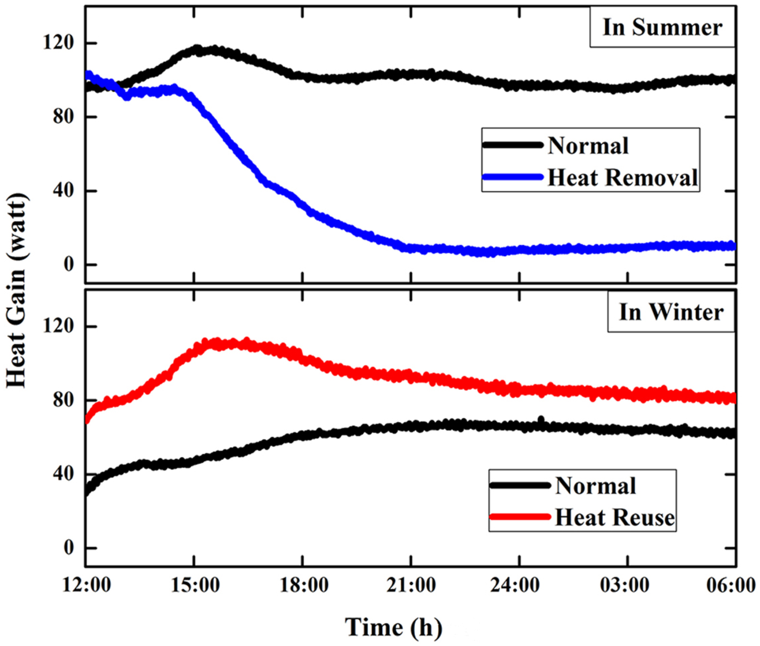
3.2. Indoor Heat Gain from LED Lighting and Temperature Distribution

The average air-temperature distribution in the vertical direction from the 25 points of the thermal sensors in the indoor and 15 points in the plenum at 00:00 (from 23:30 to 00:30) during both summer and winter are shown in Figure 5. As the window was on the north wall (left side) and the control room was adjacent to the south wall, the horizontal air-temperature distribution was slightly non-uniform towards each side. The isotherm line interval is 0.5 °C.
Figure 5. Vertical temperature distribution for the ATOS with seasonal strategy: (a) in summer without heat removal; (b) in summer with lighting heat removal; (c) in winter without heat reuse; (d) in winter with lighting heat reuse.
Energies 08 08736 g005
In summer, the indoor air temperature with heat removal was 3.9 °C lower than in the case without heat removal (25.2 °C), and the plenum temperature was 5.2 °C lower than in the case without heat removal (27.8 °C). The outdoor temperatures for the cases with and without heat removal were 16.4 °C and 18.4 °C, respectively. Although the outdoor temperature for the case without heat removal was 2.0 °C higher, the lighting heat removal to the outdoors was effective in indoor cooling and could reduce the indoor cooling load. In winter, when the lighting heat was transferred to the indoor space through air flow, the indoor temperature was 1.1 °C higher than in the case without heat reuse (1.0 °C), and the outdoor temperatures for the cases with and without heat reuse were −4.4 °C and −4.7 °C, respectively. The detailed results according to the height of measurement are listed in Table 2. This result indicates that the lighting heat reused in the indoor space can enhance the indoor heat gain from lighting, although a little heat loss occurs to the outdoors.
Table 2. Air temperatures of the indoor space and plenum with and without the ATOS.
ZoneIndoor spacePlenum areaOutdoor
Height (m)0.051.052.05Avg.0.050.250.50Avg.
Air temperatures in summer (°C)Without heat removal24.425.026.325.227.727.927.827.818.4
With heat removal20.921.321.721.322.622.622.822.616.4
Air temperatures in winter (°C)Without heat removal0.00.92.61.02.52.84.63.3−4.7
With heat removal1.12.12.82.12.83.03.43.0−4.4
In summer, the entire lighting heat is transferred as conductive heat through the ceiling board when LED lighting is typically installed on the ceiling because of the high outdoor temperature, as evident from Equation (2). Thus, when the LED lighting heat is removed, the indoor heat gain can be expressed as:
Q i n = U c A c ( T p l T i n )
where Uc is the heat transfer coefficient of the ceiling board; Ac is the area of the ceiling board, and Tpl and Tin are the air temperatures of the plenum and indoor space, respectively. In winter, it is possible to recover the lighting heat loss by supplying air to pass through the heat sink to the indoor space. Thus, the enhanced heat gain is expressed as:
Q i n , s = ρ c v A d ( T f T r )
where ρ, c, and v are the air density, specific heat capacity, and air flow rate, respectively; Ad is the cross-section area of the air duct, and Tf and Tr are the air temperatures of the front and rear of the heat sink, respectively.
Figure 6 shows the indoor heat gain calculated using experimental results from 12:00 to 06:00 in both summer and winter. In the normal case of the summer season and the heat reuse case of the winter season, the indoor heat gain was increased to the peak value at 15:00 because the solar radiation in a clear sky directly affects the thermal conditions of the indoor space and plenum. To avoid this solar radiation from overheating the indoor and plenum of the mock-up chamber, the indoor heat gain was compared after sunset, especially at the steady state from 00:00 to 06:00 when the calculated results show constant values.
In summer season, the indoor heat gain was calculated using Equation (3). In the result, the indoor heat gain was reduced by 90.5% from 97.78 W to 9.31 W by transferring the lighting heat to the outdoors using air flow. The reduced heat gain under the ATOS control (9.31 W) indicates that only 7.8% of the heat from the 120-W LED lighting affects the indoor heat gain and cooling load in summer, while 81.5% of the lighting power is transferred to the indoor space in the case without heat removal. In addition, the heat gain in winter with lighting heat reuse was calculated using Equations (3) and (4) to be 30.2% higher than in the case without heat reuse, representing an increase from 64.29 W to 83.73 W. Therefore, the ATOS in winter is expected to improve the lighting heat recovery rate by 16.2% for the indoor heating load. The calculated indoor heat gains and the lighting heat contribution rate for indoor heat gain with and without the ATOS are listed in Table 3.
Figure 6. Indoor heat gain effect of ATOS seasonal strategy (blue: heat removal in summer; red: heat reuse in winter).
Energies 08 08736 g006
Table 3. Experimental results with and without the ATOS control.
Operation typeSummerWinter
NormalHeat removalNormalHeat reuse
Indoor heat gain (Qin)97.78 W9.31 W64.29 W83.73 W
Contribution rate (Qin/PLED a)81.5%7.8%53.6%69.8%
a PLED represents the electric power of the LED.

3.3. Predicted Building Energy Savings

In order to predict the heating and cooling energy reduction in an office building using ATOS, we applied the reference office building model that consists of a core zone with four perimeter zones (as provided by the U.S. Department of Energy) by using the simulation program EnergyPlus [28]. As listed in Table 3, we applied the seasonal lighting heat contribution rate for indoor heat gain to compare the energy consumptions with and without our proposed method. In the simulated building, a lighting power density of 8.60 W/m2 was applied for LED lighting of 100 lm/W, and the total floor area was 511 m2. For the HVAC system, the minimum ventilation rate was set at 2.5 L/s person [29], a gas furnace and packaged air-conditioning unit were used, and the thermostat was set at 21 °C for heating and 24 °C for cooling. We used weather data for Daejeon, South Korea, which is at a latitude of 127.22 °E and longitude of 36.22 °N. Occupancy, lighting, plug load, and thermal performance of the envelopes for EnergyPlus are summarized in Table 4.
Table 4. Specifications of the reference office building in EnergyPlus.
Input parameter
Internal heat gains
Equipment
-
10.76 W/m2
8.60 W/m2
120 W/person
Lighting
Occupancy
U-value of Envelopes
Exterior wall
Roof
Floor
Window
-
0.86 W/(m2K)
0.19 W/(m2K)
1.86 W/(m2K)
3.24 W/(m2K)
Figure 7 shows the simulation results of heating and cooling energy consumption in the reference building model. In the ATOS case, the annual total energy consumption including heating, cooling, lighting, ventilating, and hot water system was reduced by 5.9% (from 114.7 to 107.9 MWh) compared to the normal case. During the cooling period (from April to September), the cooling energy savings were estimated to be 18.4% because of the low amount of lighting heat transferred to the indoor space, and during the heating period (from October to March), the heating energy savings were estimated to be 3.3% because of the enhanced heat gain from the lighting. Furthermore, there was no additional energy consumption of the fan to exchange the lighting heat entirely and maintain the required interior illuminance in the ATOS, because the ventilation fan was operated constantly during working hours to meet the minimum ventilation requirement of the indoor space.
Figure 7. Monthly energy consumption for heating and cooling and the annual total energy savings of the reference commercial building model under ATOS control.
Energies 08 08736 g007

4. Conclusions

We proposed an alternative thermal operating system with a seasonal strategy for indoor LED lighting that provides a synergetic effect between lighting efficiency and energy reduction for heating and cooling in a building. A field measurement was performed to verify the LED illuminance enhancement through active cooling and the indoor thermal effect through the removal and reuse of lighting heat for heating and cooling load reduction, respectively. LED lighting illuminance in a heat-exchange module integrated with an HVAC duct decreased by 39.8% when the HVAC fan operation stopped, and the air temperature of the module increased from 22.5 °C to 39.3 °C. The illuminance and temperature were restored to the initial levels when the HVAC fan was restarted. The results show that with our proposed method, it is possible to enhance the lighting efficiency by cooling the LED devices and to reduce the cooling load in buildings because of the low indoor heat gain from lighting. We confirmed that the lighting heat contributed to the indoor heat gain by analyzing the experimental data during summer and winter. In summer, the indoor air temperature was 3.9 °C lower with lighting heat removal, and in winter, the indoor air temperature was 1.1 °C higher with lighting heat reuse. Furthermore, with the use of the ATOS, the indoor heat gain at the steady state was reduced by 90.5% with heat removal and increased by 30.2% with heat reuse. To predict the annual energy savings, we conducted a simulation using a reference commercial building based on the experimental data for lighting heat contribution in indoor heat gain. The cooling and heating energy savings were estimated to be 18.4% and 3.3%, respectively, and the annual energy savings were predicted to be approximately 5.9%.
We compared the indoor thermal effects in a mock-up chamber with the thermal management method using the high-power COB LED lighting application, which has a high heat flux in a small area. However, in the case of a mid-power LED in a large area with low heat flux such as LED lighting with a surface mounted device (SMD), which will enter the mainstream of the building lighting market in the near future, a more detailed approach considering the heat pipe and heat sink system is required for enhancing the heat-transfer rate (e.g., an integrated design of the LED lighting system with the ATOS module). In addition, the distance between the lighting and duct is one of the most significant factors determining the benefits of our method; therefore, this method will be more suitable for newly built buildings with LED lightings, simultaneously considering a duct line design and the locations of lighting fixtures.

Acknowledgments

This work was supported by a National Research Foundation of Korea (NRF) grant funded by the Korean government (MSIP) (No. 2011-0028075).

Author Contributions

All the authors were involved in preparing the manuscript. Cheol-Yong Jang provided guidance and supervision. Byung-lip Ahn implemented the main research, checked results, wrote the paper, and discussed the results. Ji-Woo Park and Seunghwan Yoo performed the experiment, Jonghun Kim and Hakgeun Jeong designed the simulations, and Seung-Bok Leigh reviewed the paper.

Conflicts of Interest

The authors declare no conflicts of interest.

References

  1. Nejat, P.; Jomehzadeh, F.; Taheri, M.M.; Gohari, M.; Majid, M.Z.A. A global review of energy consumption, CO2 emissions and policy in the residential sector (with an overview of the top ten CO2 emitting countries). Renew. Sustain. Energy Rev. 2015, 43, 843–862. [Google Scholar] [CrossRef]
  2. Napp, T.A.; Gambhir, A.; Hills, T.P.; Florin, N.; Fennell, P.S. A review of the technologies, economics and policy instruments for decarbonising energy-intensive manufacturing industries. Renew. Sustain. Energy Rev. 2014, 30, 616–640. [Google Scholar] [CrossRef]
  3. Deng, S.; Wang, R.Z.; Dai, Y.J. How to evaluate performance of net zero energy building—A literature research. Energy 2014, 71, 1–16. [Google Scholar] [CrossRef]
  4. Omer, A.M. Energy, environment and sustainable development. Renew. Sustain. Energy Rev. 2008, 12, 2265–2300. [Google Scholar] [CrossRef]
  5. Yoo, S.; Jeong, H.; Ahn, B.-L.; Han, H.; Seo, D.; Lee, J.; Jang, C.-Y. Thermal transmittance of window systems and effects on building heating energy use and energy efficiency ratings in South Korea. Energy Build. 2013, 67, 236–244. [Google Scholar] [CrossRef]
  6. Pérez-Lombard, L.; Ortiz, J.; Coronel, J.F.; Maestre, I.R. A review of HVAC systems requirements in building energy regulations. Energy Build. 2011, 43, 255–268. [Google Scholar] [CrossRef]
  7. Li, D.H.W.; Yang, L.; Lam, J.C. Zero energy buildings and sustainable development implications—A review. Energy 2013, 54, 1–10. [Google Scholar] [CrossRef]
  8. Dubois, M.-C.; Blomsterberg, A. Energy saving potential and strategies for electric lighting in future north European, low energy office buildings: a literature review. Energy Build. 2011, 43, 2572–2582. [Google Scholar] [CrossRef]
  9. Tsuei, C.-H.; Sun, W.-S.; Kuo, C.-C. Hybrid sunlight/LED illumination and renewable solar energy saving concepts for indoor lighting. Opt. Express 2010, 18, A640–A653. [Google Scholar] [CrossRef] [PubMed]
  10. Adriaenssens, S.; Rhode-Barbarigos, L.; Kilian, A.; Baverel, O.; Charpentier, V.; Horner, M.; Buzatu, D. Dialectic form finding of passive and adaptive shading enclosures. Energies 2014, 7, 5201–5220. [Google Scholar] [CrossRef]
  11. Yoon, Y.B.; Manandhar, R.; Lee, K.H. Comparative study of two daylighting analysis methods with regard to window orientation and interior wall reflectance. Energies 2014, 7, 5825–5846. [Google Scholar] [CrossRef]
  12. Djavid, M.; Liu, X.; Mi, Z. Improvement of the light extraction efficiency of GaN-based LEDs using rolled-up nanotube arrays. Opt. Express 2014, 22, A1680–A1686. [Google Scholar] [CrossRef] [PubMed]
  13. Horng, R.-H.; Wu, B.-R.; Tien, C.-H.; Ou, S.-L.; Yang, M.-H.; Kuo, H.-C.; Wuu, D.-S. Performance of GaN-based light-emitting diodes fabricated using GaN epilayers grown on silicon substrates. Opt. Express 2014, 22, A179–A187. [Google Scholar] [CrossRef] [PubMed]
  14. Cheng, H.H.; Huang, D.-S.; Lin, M.-T. Heat dissipation design and analysis of high power LED array using the finite element method. Microelectron. Reliab. 2012, 52, 905–911. [Google Scholar] [CrossRef]
  15. Jang, D.; Yook, S.-J.; Lee, K.S. Optimum design of a radial heat sink with a fin-height profile for high-power LED lighting applications. Appl. Energy 2014, 116, 260–268. [Google Scholar] [CrossRef]
  16. Tamura, T.; Setomoto, T.; Taguchi, T. Illumination characteristics of lighting array using 10 candela-class white LEDs under AC 100 V operation. J. Lumin. 2000, 87–89, 1180–1182. [Google Scholar] [CrossRef]
  17. Yang, K.-S.; Chung, C.-H.; Lee, M.-T.; Chiang, S.-B.; Wong, C.-C.; Wang, C.-C. An experimental study on the heat dissipation of LED lighting module using metal/carbon foam. Int. Commun. Heat Mass Transf. 2013, 48, 73–79. [Google Scholar] [CrossRef]
  18. Schubert, E.F.; Kim, J.K. Solid-state light sources getting smart. Science 2005, 308, 1274–1278. [Google Scholar] [CrossRef] [PubMed]
  19. Christensen, A.; Graham, S. Thermal effects in packaging high power light emitting diode arrays. Appl. Therm. Eng. 2009, 29, 364–371. [Google Scholar] [CrossRef]
  20. Ramos-Alvarado, B.; Feng, B.; Peterson, G.P. Comparison and optimization of single-phase liquid cooling devices for the heat dissipation of high-power LED arrays. Appl. Therm. Eng. 2013, 59, 648–659. [Google Scholar] [CrossRef]
  21. Lam, J.C.; Tsang, C.L.; Yang, L. Impacts of lighting density on heating and cooling loads in different climates in China. Energy Convers. Manag. 2006, 47, 1942–1953. [Google Scholar] [CrossRef]
  22. Sezgen, O.; Koomey, J.G. Interactions between lighting and space conditioning energy use in US commercial buildings. Energy 2000, 25, 793–805. [Google Scholar] [CrossRef]
  23. Ahn, B.-L.; Jang, C.-Y.; Leigh, S.-B.; Yoo, S.; Jeong, H. Effect of LED lighting on the cooling heating loads in office buildings. Appl. Energy 2014, 113, 1484–1489. [Google Scholar] [CrossRef]
  24. U.S. Department of Energy, Energy Efficiency and Renewable Energy. Thermal Management of White LEDs; U.S. Department of Energy, Energy Efficiency and Renewable Energy: Washington, DC, USA, 2007.
  25. American Society of Heating, Refrigerating and Air-Conditioning Engineers (ASHRAE), Inc. 2013 ASHRAE Handbook––Fundamentals, Ventilation and Infiltration, American Society of Heating; ASHRAE Inc.: Atlanta, GA, USA, 2013.
  26. U.S. Department of Energy. Standard Measurement and Verification Plan for Lighting Retrofit Projects for Buildings and Building Sites; Pacific Northwest National Laboratory: Richland, WA, USA, 2012.
  27. Lawrence Berkeley National Laboratory. WINDOW 6.3 Glass Library, 2012. Available online: https://windows.lbl.gov/software/window/window.html (accessed on 29 June 2015).
  28. U.S. Department of Energy. Commercial Reference Building Models of the National Building Stock; National Renewable Energy Laboratory: Golden, CO, USA, 2011.
  29. American Society of Heating, Refrigerating and Air-Conditioning Engineers (ASHRAE), Inc. 2001 ASHRAE Standard 62, Ventilation for Acceptable Indoor Air Quality; ASHRAE Inc.: Atlanta, GA, USA, 2001.

