1. Introduction
In the development of adsorption heat pumps and chillers over the past decades, it has been a persistent goal to increase the volume-specific cooling or heating power to achieve more compact and light-weight units. The design of improved adsorption heat exchangers continues to take a central place in this effort.
Perhaps the simplest concept of an adsorption heat exchanger is a bed of adsorbent grains in a volume, part of which is occupied by some kind of heat exchanger. This configuration is widely used, and it can simply be obtained by pouring adsorbent grains into the volume in which the heat exchanger has been placed, and possibly densifying the bed by vibration. Whereas in standard applications of adsorbent beds (such as gas separation) the focus is on selectivity, for heat pumps and chillers the focus is on the heat of adsorption and the intensity of the heat transfer processes (during exothermal adsorption and endothermal desorption).
Therefore, the enhancement of heat conductivity within the adsorbent layer or bed is discussed by many authors (see e.g., references in [
1]). The best heat transfer achievable as the limiting case of an adsorbent bed is obtained for a single layer of adsorbent grains on each heat exchanger surface, which is an approach taken, for example, in some zeolite/water heat pumps that have become available on the market recently ([
2,
3,
4]). As an alternative to designs with a single adsorbent bed, additives have been proposed to enhance thermal conductivity. Wang
et al. [
5] have shown that a composite of polyaniline and adsorbents leads to a four-fold rise in thermal conductivity of the bed, whereas the compression of the bed improves it only by a factor of 1.5. Zhang [
6] enhances the heat transfer in a cylindrical double tube by inserting fins in an adsorbent bed, whereas Demir
et al. [
7] and Rezk, Al-Dadah, Mahmoud, and Elsayed [
1] investigate the effect of metal additives. Many experimental investigations on the performance of adsorbent beds in combination with finned tubes or lamella heat exchangers have been done [
8,
9,
10,
11]. Other authors propose to use commercially available plate-fin heat exchangers [
12,
13,
14]. An overview on different concepts is given by Sharafian and Bahrami [
15]. Here, the mass-specific cooling power ranges from 0.02 to 0.8 kW/kg of the adsorbent. Improvement of the thermal contact between the adsorbent and the heat exchanger, beyond the “packed bed” concept in its “single layer of grains” limit, can be achieved by increasing the contact surface through a binding agent or glue.
Coating the heat exchanger surface directly reduces the thermal contact resistance between the heat exchanger and the adsorbent. Jaeschke and Wolf [
16] propose to glue a single layer of silica gel onto the surface of a finned-tube heat exchanger, whereas Freni
et al. [
17] report an increase by a factor of 10 to 20 in power density for a binder-based coating with the silica gel/calcium chloride composite material SWS-1L onto finned tubes compared to a granular bed. Other binder-based coatings show similar behavior [
18,
19].
Direct crystallization allows binding the pure adsorbent directly onto the heat exchanger surface. The absence of additional material augments the mass ratio of adsorbent to non-adsorbent material [
20] and often shows a high stability [
21,
22]. In some cases, direct crystallization leads to a much more compact adsorbent layer (with a density close to the single-crystal density) than is achievable through a coating process. Different materials such as aluminum [
23,
24], copper [
25], stainless steel [
26], or graphite [
27] can be used as a substrate.
Thick layers result in a higher adsorbent mass and thus an increase in Coefficients of Performance (COPs), but mass transfer may become the limiting factor. Especially when using water as a working fluid, the low operating pressure restricts the thickness of compact layers, whereas other working pairs like ammonia/activated carbon with a high operating pressure show less sensitivity to this restriction [
28]. To overcome this issue, the surface area of the heat exchanger has to be enlarged considerably. The use of honeycomb structures [
29], foams [
25,
30], or fiber material [
31] has been proposed. Recently, Tatlier
et al. [
32] investigated coatings of zeolite A on stainless steel plates with different layer thickness (58–176 μm). They show that up to a certain layer thickness, the higher amount of adsorbents can compensate the reduction in rate of adsorption. Under the conditions investigated, an optimum was found for a layer thickness of 130–140 μm. An overview on recent developments in the field of coated adsorption heat exchangers and their characterization can be found in [
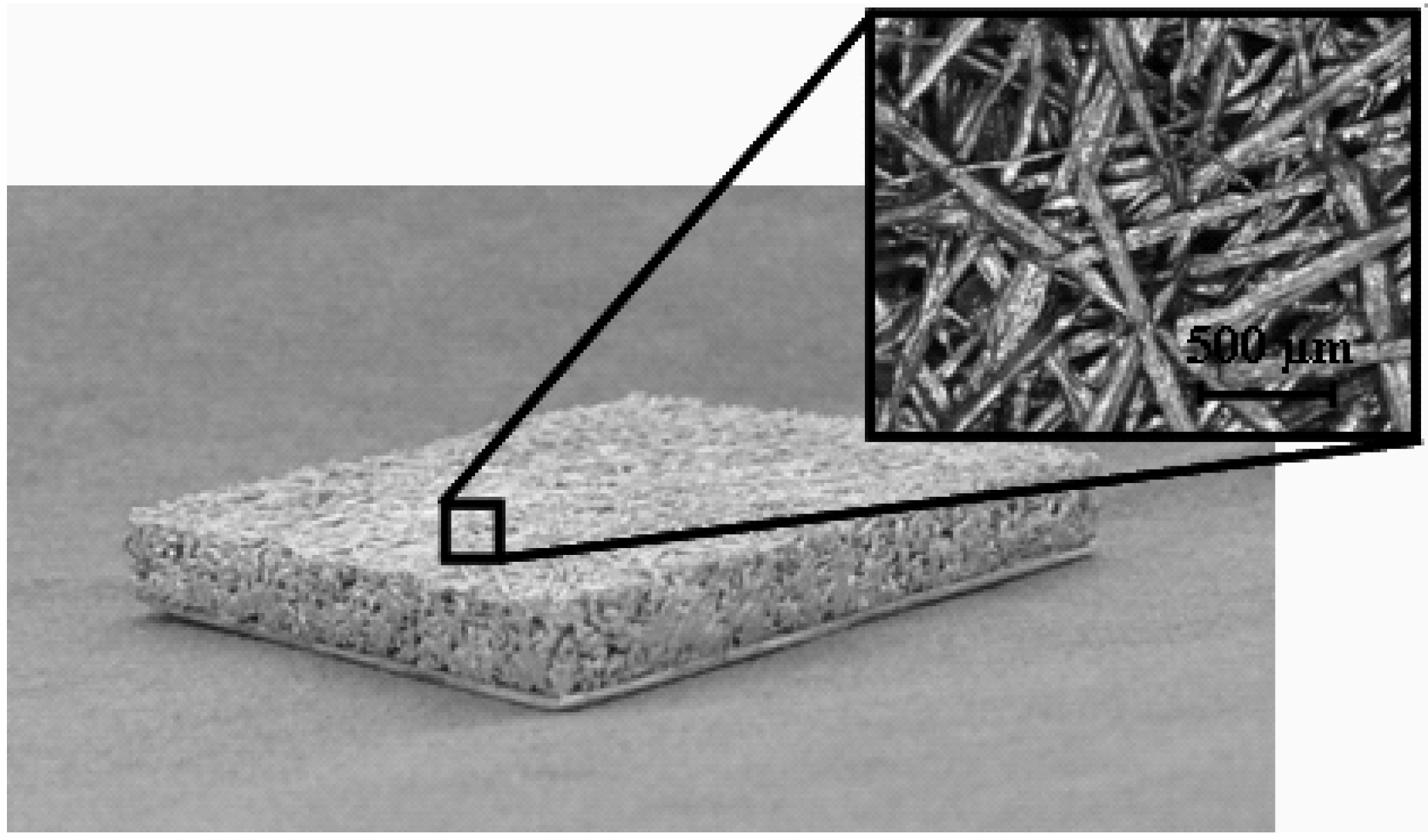
33]. In this paper, we present a novel composite material of aluminum fibers coated by a silico-alumino-phosphate (SAPO-34) with a chabasite structure using a partial support transformation (PST) method as described by Bauer, Herrmann, Mittelbach, and Schwieger [
23]. SAPO-34 has been shown to be a suitable adsorbent for heat transformation of low grade heat (<100 °C) [
34,
35,
36,
37]. Both the characteristics of the fiber material and the fiber-adsorbent composite are investigated. The application in adsorption processes is shown for small samples (30 mm × 30 mm × 3.9 mm). Finally, the feasibility of the scale-up to a new type of compact adsorption heat exchanger is presented and its water uptake behavior is examined.
3. Adsorption Characteristics of Small Sample
The adsorption behavior of the small sample of the composite material (see
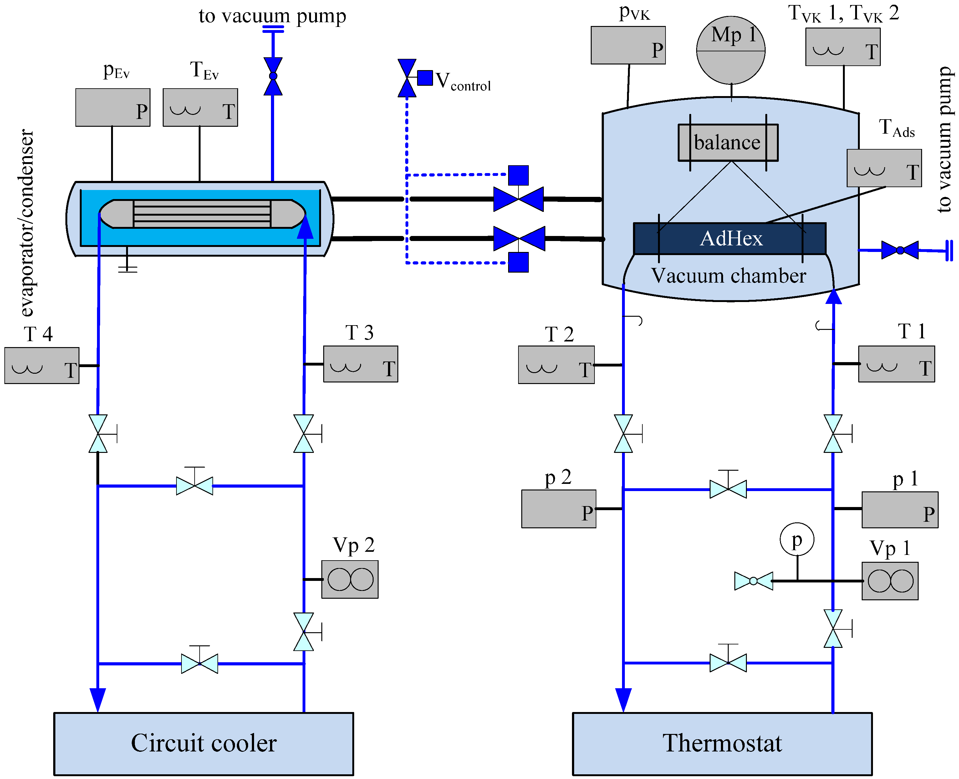
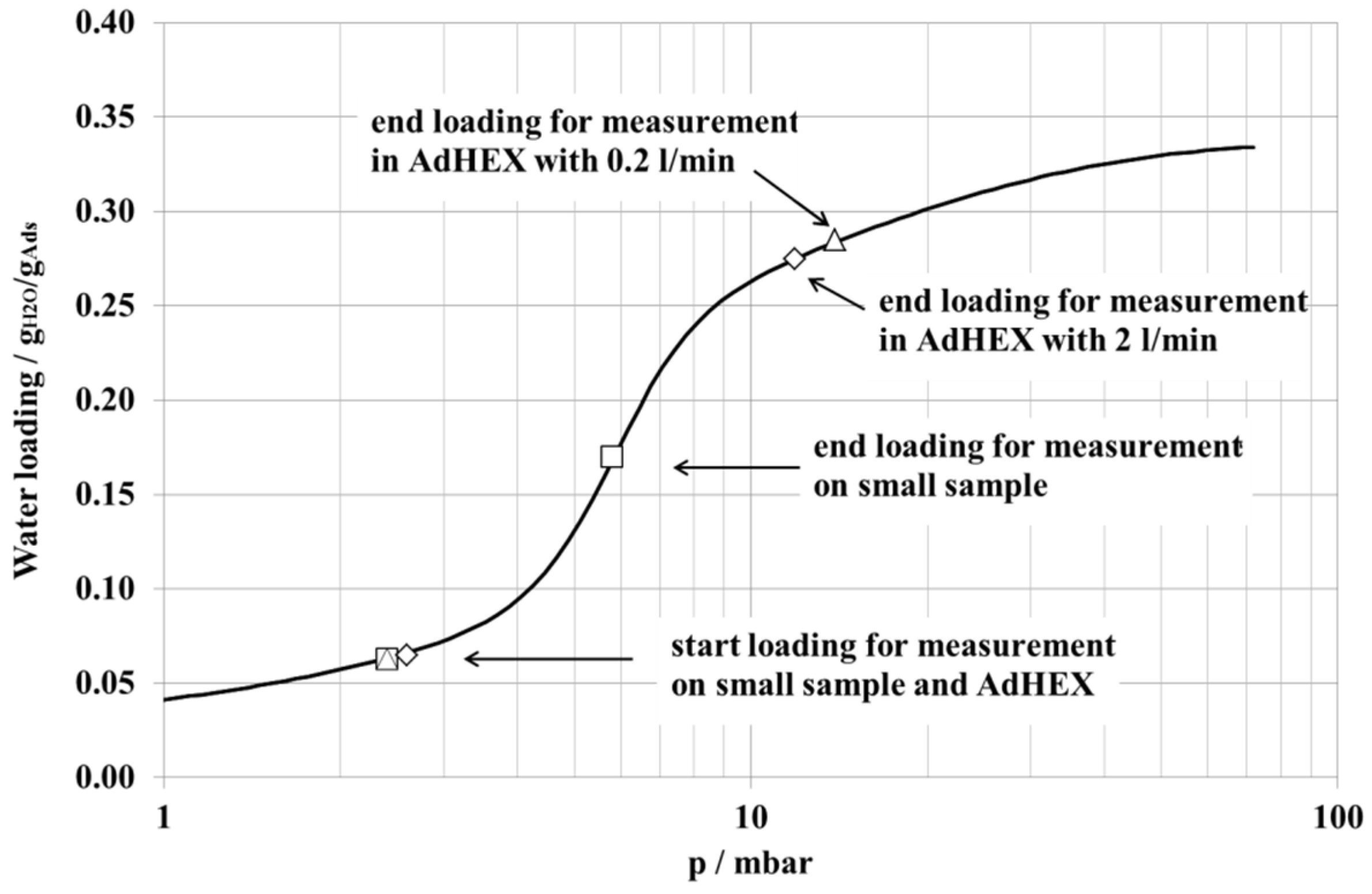
Figure 2) has been investigated by a Large Pressure Jump (LPJ) method in a set-up described by Schnabel, Tatlier, Schmidt, and Erdem-Şenatalar [
25]. The sample is placed on a cold plate in a vacuum chamber: thermostats control the temperature of the cold plate and the sample is desorbed (here: at 95 °C), either against a vacuum pump or against a temperature-controlled water flask, setting a certain condenser pressure for the desorption process and thus enabling the preparation of the sample at a well-defined initial adsorbate loading. The pressure in the vapor chamber is the saturation pressure of the water flask (here: 10 °C,
i.e., 12 mbar). The sample is cooled down to an adsorption temperature of 38.7 °C and adsorption is started by opening the valve between the vapor chamber and the measurement cell. The decrease in pressure in the combined volume over time is detected by a pressure sensor and the amount of water adsorbed by the sample can thus be determined with an accuracy of ±5% under the assumption that water vapor is an ideal gas [
46] (see
Figure 3 and
Figure 4).
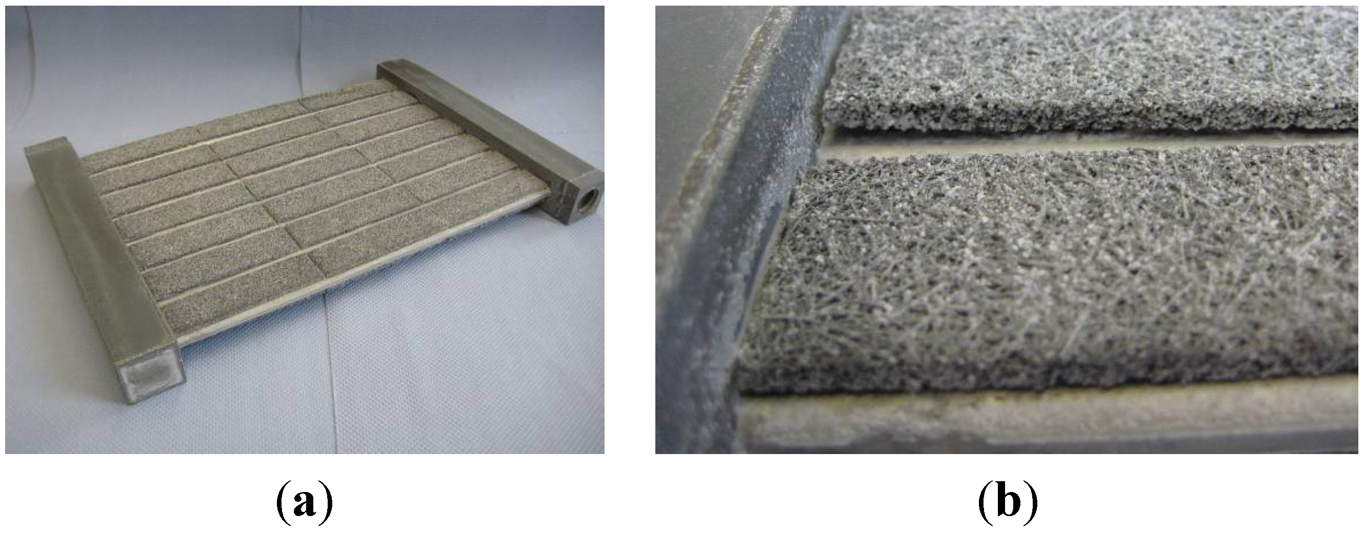
Figure 2.
Sample of fiber-SAPO-34 composite material (0.03 m × 0.03 m × 0.0039 m), carrier: Al sheet of 0.4 mm thickness.
Figure 2.
Sample of fiber-SAPO-34 composite material (0.03 m × 0.03 m × 0.0039 m), carrier: Al sheet of 0.4 mm thickness.
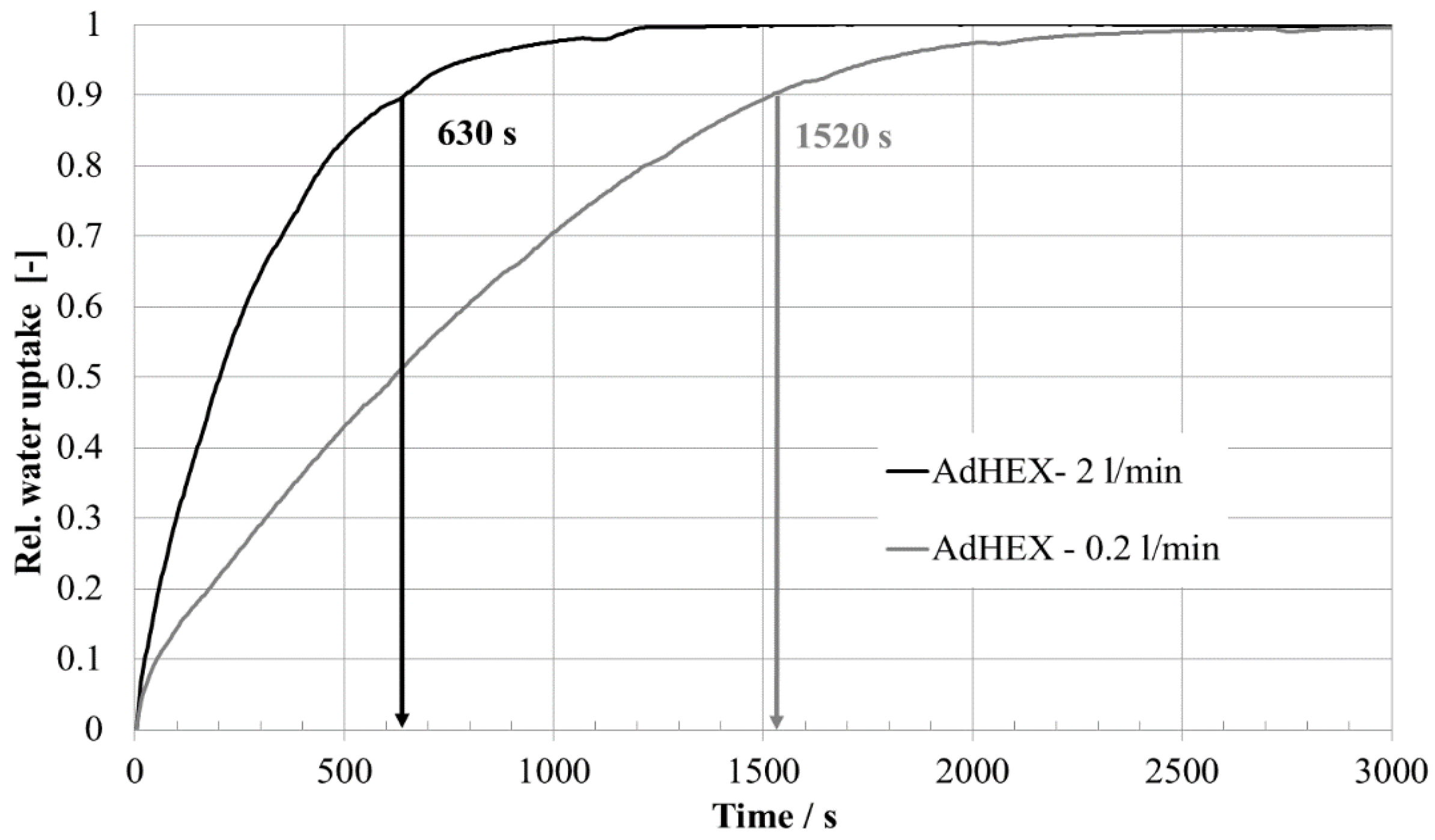
Figure 3.
Water uptake (relative to final uptake) over time at 38.7 °C for small sample at a start loading of 0.06 gH2O/gAde.
Figure 3.
Water uptake (relative to final uptake) over time at 38.7 °C for small sample at a start loading of 0.06 gH2O/gAde.
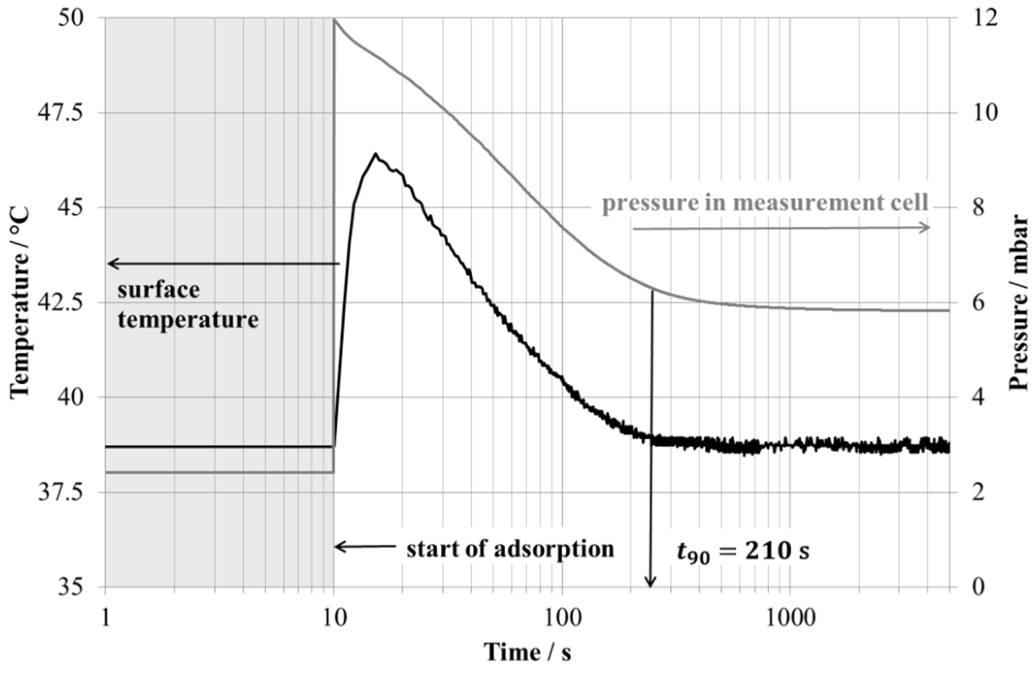
Figure 4.
Surface temperature of sample and vapor pressure in measurement cell during water uptake as shown in
Figure 3.
Figure 4.
Surface temperature of sample and vapor pressure in measurement cell during water uptake as shown in
Figure 3.
Figure 3 shows the water uptake over time measured at 38.7 °C. Further results are given in
Table 2.
Table 2.
Main parameters of small sample and prototype.
Table 2.
Main parameters of small sample and prototype.
| Parameter | Unit | Small Sample | Prototype |
|---|
| Volume | | | |
| Total | m3 | 0.0039 × 10⁻³ | 3 × 10⁻³ a |
| Profiles/support | m3 | 0.0004 × 10⁻³ | 0.495 × 10⁻³ |
| Fiber | m3 | 0.0035 × 10⁻³ | 0.315 × 10⁻³ |
| Mass | | | |
| Mass adsorbent | kg | 2.2 × 10⁻³ | 0.240 |
| Total mass b | kg | 6.8 × 10⁻³ | 1.350 |
| Specific values | | | |
| Mass adsorbent per total mass | kg/kg | 0.32 | 0.18 |
| Mass adsorbent per volume composite | kg/m3 | 620 | 760 |
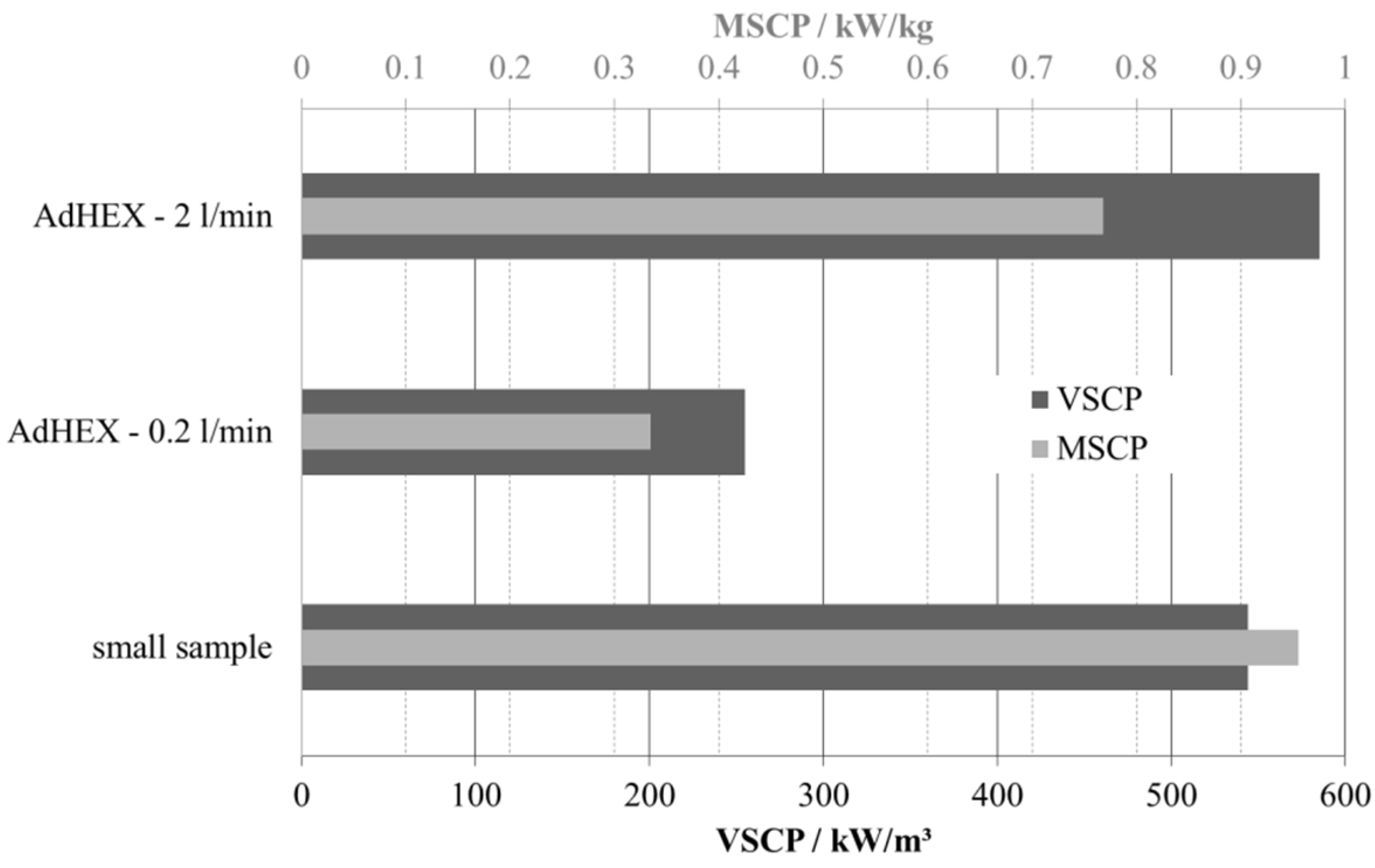
The sample adsorbs 180 mg of water in a short time: the time to reach 90% of the final uptake (t90) is 210 s, which leads to a volume-specific cooling power density of over 500 kW/m3 of the composite material.


 ,
, 
