Article

Analysis on the Initial Cracking Parameters of Cross-Measure Hydraulic Fracture in Underground Coal Mines

1
State Key Laboratory of Coal Mine Disaster Dynamics and Control, Chongqing University, Chongqing 400044, China
2
National & Local Joint Engineering Laboratory of Gas Drainage in Complex Coal Seam, Chongqing University, Chongqing 400044, China
3
Songzao Coal-Electricity Limited Liability Company, Chongqing 401445, China
*
Authors to whom correspondence should be addressed.
Energies 2015, 8(7), 6977-6994; https://doi.org/10.3390/en8076977
Submission received: 27 May 2015 / Revised: 1 July 2015 / Accepted: 2 July 2015 / Published: 10 July 2015

Abstract

:
Initial cracking pressure and locations are important parameters in conducting cross-measure hydraulic fracturing to enhance coal seam permeability in underground coalmines, which are significantly influenced by in-situ stress and occurrence of coal seam. In this study, stress state around cross-measure fracturing boreholes was analyzed using in-situ stress coordinate transformation, then a mathematical model was developed to evaluate initial cracking parameters of borehole assuming the maximum tensile stress criterion. Subsequently, the influences of in-situ stress and occurrence of coal seams on initial cracking pressure and locations in underground coalmines were analyzed using the proposed model. Finally, the proposed model was verified with field test data. The results suggest that the initial cracking pressure increases with the depth cover and coal seam dip angle. However, it decreases with the increase in azimuth of major principle stress. The results also indicate that the initial cracking locations concentrated in the second and fourth quadrant in polar coordinate, and shifted direction to the strike of coal seam as coal seam dip angle and azimuth of maximum principle stress increase. Field investigation revealed consistent rule with the developed model that the initial cracking pressure increases with the coal seam dip angle. Therefore, the proposed mathematical model provides theoretical insight to analyze the initial cracking parameters during cross-measure hydraulic fracturing for underground coalmines.

1. Introduction

High efficient extraction of coal bed methane is of great importance to the safety of coalmine production and the development of state energy strategy in China [1]. The gas pre-extraction technique by boreholes has been widely used to recover the underground coal bed methane and hence prevent coalmine disasters [2,3]. In practice, the permeability of coal seams plays an important role in coal bed methane extraction [4,5,6]. Research efforts in recent year have proved that the hydraulic fracturing technology can enhance the coal seam permeability significantly, and has been used during the stages of coal roadway development and rock cross-cut coal uncovering, where a special technique of cross-measure hydraulic fracture is usually used [7]. In the implementation of cross-measure hydraulic fracturing, boreholes are drilled through seam floor into the targeted coal seam in a special gas roadway or main gate road. The typical spatial relationship between the borehole and coal seams is shown in Figure 1. In mine sites, pumping pressure of hydraulic fracturing is empirically elevated to seek a wide range of hydraulic fracture. However, as a side effect, meanwhile this incurs the risk of damaging the integrity of coal seam roof and floor, making the stability of roadway difficult to maintain. Therefore, it is very important to analyze the initial cracking parameters of cross-measure hydraulic fracturing. This would help reveal the initiation mechanism and provide theoretical guidance for implementing suitable cross-measure hydraulic fracturing technology.
Figure 1. Relationship between the fracturing boreholes and coal seams.
Energies 08 06977 g001
In order to better understand the fracturing initiation mechanism, many studies have been performed in the literature, and substantial studies have been conducted focusing on the influences of the in-situ stress, coal and rock mass strength and pore pressure. For the first time, Hubbert and Willis reported the development of longitudinal cracks in vertical boreholes in oil and gas well fracturing activities, and established the correlation of the horizontal principle stress, rock tensile strength, and pore pressure with pump pressure [8]. Schmidt and Zoback considered the influence of porosity and Poisson ratio on the pressure of crack initiation when studying the initiation mechanism in both permeable and impermeable rocks [9]. Zhang and Jeffrey investigated the effect of major and intermediate principle stresses on the crack initiation and propagation, and discussed the influence of misalignment and crack numbers on the crack initiation location near the well [10]. Huang and Griffiths et al. found the relationship between the initiation pressure, initiation location, azimuth of cracks and deviation well angles, and well azimuth by transforming the coordinates of in-situ stress to well wall stress [11,12]. Chen et al. found that borehole wall crack initiation was influenced by the level and direction of in-situ stress as well as borehole dig angle [13]. Using two-dimensional particle flow code—PFC2D, Wang et al. investigated relevant parameters and analyzed the correlation between macroscopic and mesoscopic mechanical parameters [14]. Zhang et al. established a two-dimensional numerical fracture model to analyze the coupled rock deformation and fluid flow in such fractures, and the results show that fracture escape from the interface is likely under the conditions of fracture growth from stiff to soft rocks, small layer-to-layer far-field stress contrasts, and moderately low fluid viscosity, and small parent fracture lengths and offset distances [15,16].
Although substantial studies have been conducted advancing the technology of hydraulic fracture, it should be noted that most studies are performed from the viewpoint of oil and gas industry. Different from hydraulic fracturing in oil and gas extraction, hydraulic fracturing in underground coalmines are of the following salient features:
(1)
Hydraulic fracturing in underground coalmines is an auxiliary technology, serving subsequent coal mining. Therefore, monotonic increase of the pump pressure during the fracturing process is not allowed to avoid damaging the integrity of coal seam roof and floor. In this aspect, Lin studied the pulsating stress wave generation, propagation and the mechanism of coal and rock breakage from the theoretical perspective [17].
(2)
The coal bed is thin and bounded by coal seam roof and floor, and it is conventionally assumed that the physical and mechanical properties of coal would not affect hydraulic fracturing initiation. However, hydraulic fracturing initiation can be influenced by other factors, such as in-situ stress and rock strength. Using numerical simulation, Lian and Lin, et al. found the rule of crack initiation and propagation influenced by in-situ stress and rock strength [18,19].
(3)
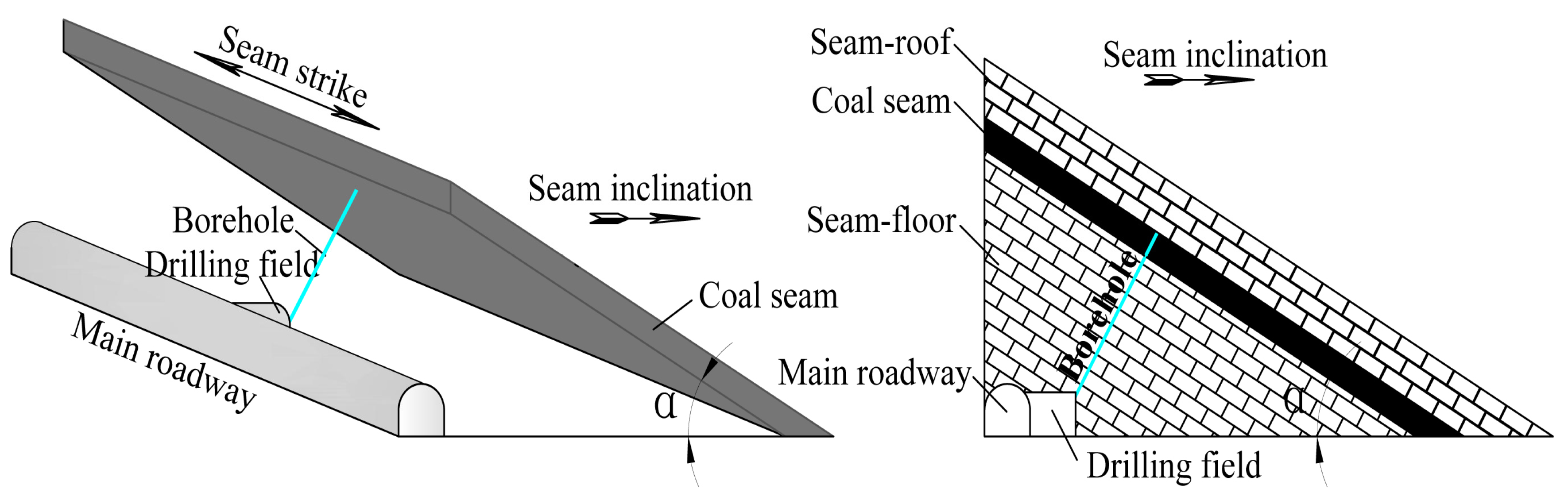
The layout of a borehole is limited by the occurrence of coal seam such as strike, inclination, and dip angle as shown in Figure 1.
Therefore, the crack initiation and propagation of coalmines by hydraulic fracturing is directly influenced by coal seam occurrence, especially by factors of strike, inclination and dip angle and in-situ stress of coal seam, and cannot be interpreted with well-developed hydraulic fracturing theory from the oil and gas industry.
The purpose of this study is to investigate the influences of the in-situ stress and coal seam dip angle on the initial cracking pressure and locations in hydraulic fracturing of underground coalmines. In this study, the stress state around cross-measure fracturing boreholes was analyzed using in-situ stress coordinate conversion, and then a model to calculate the initiation parameters of the borehole was developed using the maximum tensile stress criterion. Finally, the developed mathematical model was verified with field data.

2. Model Development

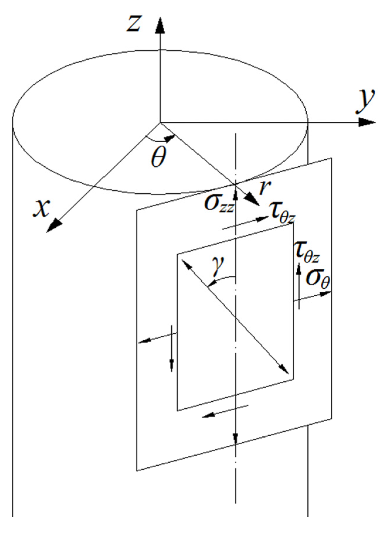
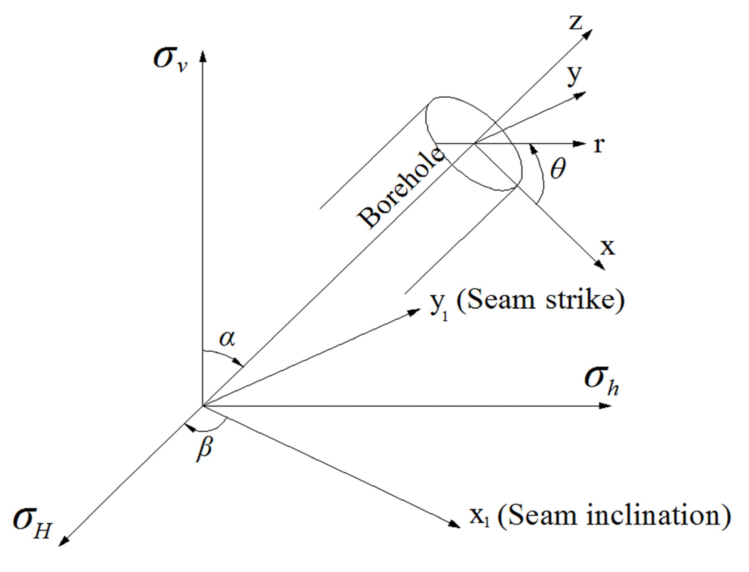
2.1. Stress Analysis for Cross-Measure Fracturing Boreholes

The stress state of a coal seam is shown in Figure 2. The analysis of the stress state around borehole was firstly performed based on the following assumptions:
(1)
Borehole is perpendicular to coal seam, as shown in Figure 1.
(2)
Taking the direction of coal seam inclination as 0°, corresponding to 0-x1 in Figure 2.
Figure 2. Stress state of the borehole.
Energies 08 06977 g002
The stress state on borehole wall can be obtained by converting the coordinate of in-situ rock stress [12].
{ σ x = ( σ H cos 2 β + σ h sin 2 β ) cos 2 α + σ v sin 2 α σ y = σ H sin 2 β + σ h cos 2 β σ z = ( σ H cos 2 β + σ h sin 2 β ) sin 2 α + σ v cos 2 α τ x y = ( σ h σ H ) cos α cos β sin β τ y z = ( σ h σ H ) sin α cos β sin β τ z x = ( σ H cos 2 β + σ h sin 2 β σ v ) 2 sin 2 α
where σv is the vertical principal stress (MPa); σH and σh are the major and minor horizontal principal stress (MPa); α is the coal seam dip angle (°); and β is the azimuth of the major principle stress (°).
Then, stress components at a distance of r from borehole caused by principle stress σH, σh, and σv can be obtained from Equation (1) [12]:
{ σ r = R 2 r 2 p + σ x + σ y 2 ( 1 R 2 r 2 ) + ( 1 + 3 R 4 r 4 4 R 2 r 2 ) σ x σ y 2 cos 2 θ + τ x y ( 1 + 3 R 4 r 4 4 R 2 r 2 ) sin 2 θ σ θ = σ x + σ y 2 ( 1 + R 2 r 2 ) R 2 r 2 p σ x σ y 2 ( 1 + 3 R 4 r 4 ) cos 2 θ τ x y ( 1 + 3 R 4 r 4 ) sin 2 θ σ z z = σ z ν [ 2 ( σ x + σ y ) R 2 r 2 cos 2 θ + 4 τ x y R 2 r 2 sin 2 θ ] τ r θ = σ y σ x 2 ( 1 3 R 4 r 4 + 2 R 2 r 2 ) sin 2 θ + τ x y ( 1 3 R 4 r 4 + 2 R 2 r 2 ) cos 2 θ τ θ z = τ y z ( 1 + R 2 r 2 ) cos θ τ x z ( 1 + R 2 r 2 ) sin θ τ z r = τ x z ( 1 R 2 r 2 ) cos θ + τ y z ( 1 R 2 r 2 ) sin θ
where R is the radius of the borehole, p is the water pressure in the borehole, and σr, σθ, σzz, τ, τθz, and τzr radial radial, tangential and axial components of normal and shear stress (MPa) at a distance of r from borehole and inclined at an angle of θ with σy, respectively.

2.2. Model for Calculation of Initial Cracking Parameters

To simplify the analysis, the implementation of cross-measure fracturing is assumed to be conducted in an elastomeric tube. In other words, the derivation only considers the factors of high water pressure and in-situ stress. The stress state of borehole walls is given by Equation (2), where r is defined as R:
{ σ r = p σ θ = ( σ x + σ y ) 2 ( σ x σ y ) cos 2 θ 4 τ x y sin 2 θ p σ z z = σ z ν [ 2 ( σ x + σ y ) cos 2 θ + 4 τ x y sin 2 θ ] τ θ z = 2 τ y z cos θ 2 τ x z sin θ τ r θ = τ z r = 0
The principle stresses on borehole walls can be obtained using Equation (3):
{ σ 1 = σ r σ 2 = 1 2 [ σ θ + σ z z + ( σ θ σ z z ) 2 + 4 τ θ z 2 ] σ 3 = 1 2 [ σ θ + σ z z ( σ θ σ z z ) 2 + 4 τ θ z 2 ]
From Equation (4), it can be seen that the initial cracking would occur in θ–z plane, as shown in Figure 3. According to the maximum tensile stress criterion, the crack initiation on borehole walls would occur when the tensile stress meets the ultimate tensile strength of coal [20]. Using Equation (4), the maximum tensile stress on borehole wall can be obtained by:
σ max = σ 3 = 1 2 [ σ θ + σ z z ( σ θ σ z z ) 2 + 4 τ θ z 2 ]
Using the concept of effective stress, the stress contributed to initiate fracture (termed “fracturing stress” in this paper) on the borehole wall can be estimated as:
σ f = σ max p 0
where p 0 is pore pressure (MPa).
The fracturing stress σf is a function of borehole pressure p through σ3, which is a function of σ θ directly related to p. However, the value of σf is not a constant at angular positions around the borehole wall. In hydraulic fracturing process, the fracture starts to grow at an angular position, say θ, with the increase of borehole pressure p from zero to the threshold. The condition for borehole wall cracking initiation can be given by Hossain et al. [21]:
σ f σ t
where σt is the coal tensile strength (MPa).
Figure 3. Stress state on the borehole wall.
Energies 08 06977 g003
The initial angular position of cracks is obtained by:
{ σ f θ = 0 2 σ f θ 2 > 0
When θ = θf, the minimum value of σf in Equation (6) can be found. If this value meets the requirement of Equation (7), the borehole will initiate. So, based on Equations (6) and (7), the fracture initiation criterion can be obtained:
σ max p 0 + σ t = 0
From Equation (9), it can be seen that rock mass of high tensile strength requires a high fracture initiation pressure, while the pore pressure p0 has a positive effect on hydraulic fracture initiation by reducing the required pressure. The research shows that the pore pressure and tensile strength of rock can be assumed as zero to achieve a conservative pressure for fracture initiation [22,23,24]. Therefore, the solution of fracture initiation criterion (Equation (9)) can be simplified as:
σ max = 0
Equations (5) and (10) can be combined to obtain the commonly used relationship
1 2 [ σ θ + σ z z ( σ θ σ z z ) 2 + 4 τ θ z 2 ] = 0
σ θ σ z z τ θ z 2 = 0
Equations (3) and (11) can be combined to obtain the simplified fracture initiation criterion
[ ( σ x + σ y ) 2 ( σ x σ y ) cos 2 θ f 4 τ x y sin 2 θ f p ] σ z z τ θ z 2 = 0
p f = ( σ x + σ y ) 2 ( σ x σ y ) cos 2 θ f 4 τ x y sin 2 θ f τ θ z 2 σ z z
As can be seen from Equations (1), (3) and (12), the initial cracking pressure (pf) and location (θf) of cross-measure fracturing are affected conjointly by coal seam dip angle (α), azimuth of maximum principle stress (β), and in-situ stress.

3. Field Experimentation

Based on the developed model of crack initiation, hydraulic fracturing trials were carried out at Tonghua coalmine in Songzao mining area (Chongqing, China), and the relationship between the crack initiation pressure and the coal seam dip angle is verified with field data. The coal seam inclination is assumed to be 0° during the test.

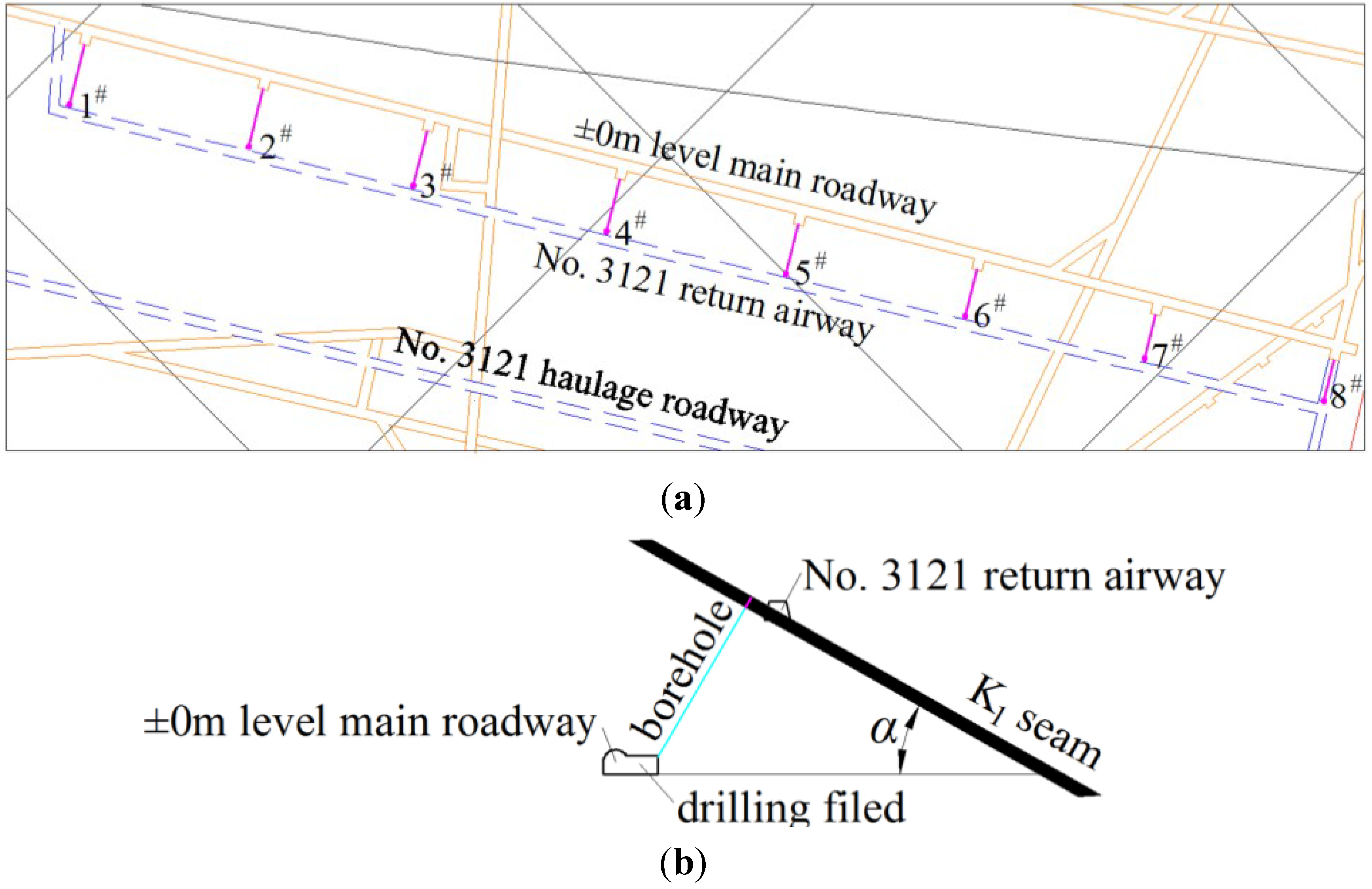
3.1. Mine-Site Condition and Borehole Layout

The hydraulic fracturing trials are conducted at ±0 m south main roadway of Tonghua coalmine, and the purpose is to drain the coal bed methane from the No. 3121 driving band air return roadway efficiently, and then tunnel the No. 3121 driving band air return roadway. There are three coal seams in this area. K1 coal seam is the targeted seam for fracturing that is usually called the “floor chamber”, with a black or slightly steel-gray color, which is a single seam that has a layered structure and massive textures with luster of metallic or semi-metallic. The depth of K1 coal seam is 500 m, with an average thickness of 1.65 m, dip angle ranging from 29.88° to 48.00°. Eight boreholes are drilled along strike of No. 3121 driving band air return roadway. Profile map of fracturing drilling is illustrated in Figure 4 and drilling parameters are listed in Table 1. The detailed sealing material and sealing craft in fracturing were used referring to Ge et al. [25].
Figure 4. The layout of the fracturing boreholes: (a) the plan of the fracturing boreholes; (b) the section of the fracturing boreholes.
Energies 08 06977 g004
Table 1. Fracturing boreholes parameters.
NumberBorehole Size/mmAzimuth Angle/°Borehole Angle/°Borehole Depth/m
1#9106030.2
2#9105733.2
3#9105535.1
4#9105337.0
5#9105039.8
6#9104742.4
7#9104445.0
8#9104246.6

3.2. In-Situ Stress Measurement in Test Site

In order to accurately obtain the relationship between the initial cracking pressure and coal seam dip angle, the technology of Kaiser effect of rock acoustic emission was used to measure in-situ stress of the rocks in fractured area. Rock cores were collected from six special directions in the measuring points of fractured rock, based on the fact that the rock has a characteristic of memorizing the original stress level. Subsequently, the rock core specimens were tested using the uniaxial compression apparatus. Kaiser points were determined from the test results, and the stress level were derived from Kaiser points, then the level and directions of in-situ stress at measuring points can be calculated using the theory of elasticity [26,27]. Figure 5 shows the rock core layout for in-situ stress tests at ±0 m south main roadway of Tonghua coalmine. Note that the convention “x” in Figure 5 is equal to “x1” in Figure 2.
Figure 5. Boreholes layout for the rock core.
Energies 08 06977 g005
The specimens of a length-to-width ratio 2:1 were cored in the field and three samples were collected in each direction (Figure 6). The main equipment for experiment includes electronic precision material testing machine and acoustic emission detection system. Table 2 shows the basic parameters of the equipment. In the loading stage, a velocity of displacement control was applied by 0.005 mm/s, and the change of ring-down count rate, energy count rate, accumulative ring-down count, accumulative energy count with elapse of time was recorded. Then, according to the observed Kaiser effect, the in-situ stress environment was derived for test site (Table 3).
Figure 6. Specimens in acoustic emission test.
Energies 08 06977 g006
Table 2. Basic parameter of equipment.
Equipment NameTypeParameters
Electronic precision material testing machineAG-I 250kN1/1000 degree loading precision, 1/1000 degree displacement control precision
Acoustic emission detection system16CHsSAMOS™ System12 channels, 40 MHz, 18 bit A/D, 1 KHz–3 MHz frequency range, 100 dB maximum signal amplitude, 40 MSPS sample rate
Table 3. Test result of in-situ stress.
CategoryThe Maximum σ1The Intermediate σ2The Minimum σ3
Principal stress /MPa23.79.94.5
θx (The angle between principal stress and x)/°39.094.651.1
θy (The angle between principal stress and y)/°129.187.838.9
θz (The angle between principal stress and z)/°86.83.488.4

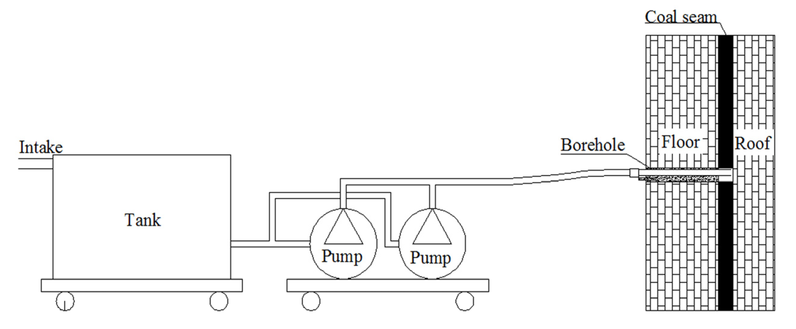
3.3. Hydraulic Fracturing Equipment for Field Test

Hydraulic fracturing test was conducted using two fracturing pumps (Liuhe Coal Mining Machinery Co. Ltd, Nanjing, China) at a flow rate of 200 L/min and a maximum working pressure of 56 MPa. As the pumps are variable displacement pumps, the pumps are used in pressure control mode. The high-pressure hydraulic fracturing system mainly consists of the fracturing pump, consoles, water tanks, water meters, pressure gauges, high-pressure pipes, sealing accessories, and relevant connecting devices, as shown in Figure 7. The fracturing fluid is water. During the fracturing process, two pumps run simultaneously. Figure 8 shows the field test of the cross-measure hydraulic fracturing in underground coalmines.
Figure 7. The connected equipment of the high-pressure hydraulic fracturing system.
Energies 08 06977 g007
Figure 8. Field test of cross-measure hydraulic fracturing in underground coalmines.
Energies 08 06977 g008

4. Results and Discussion

4.1. Analysis on the Initiation Parameters

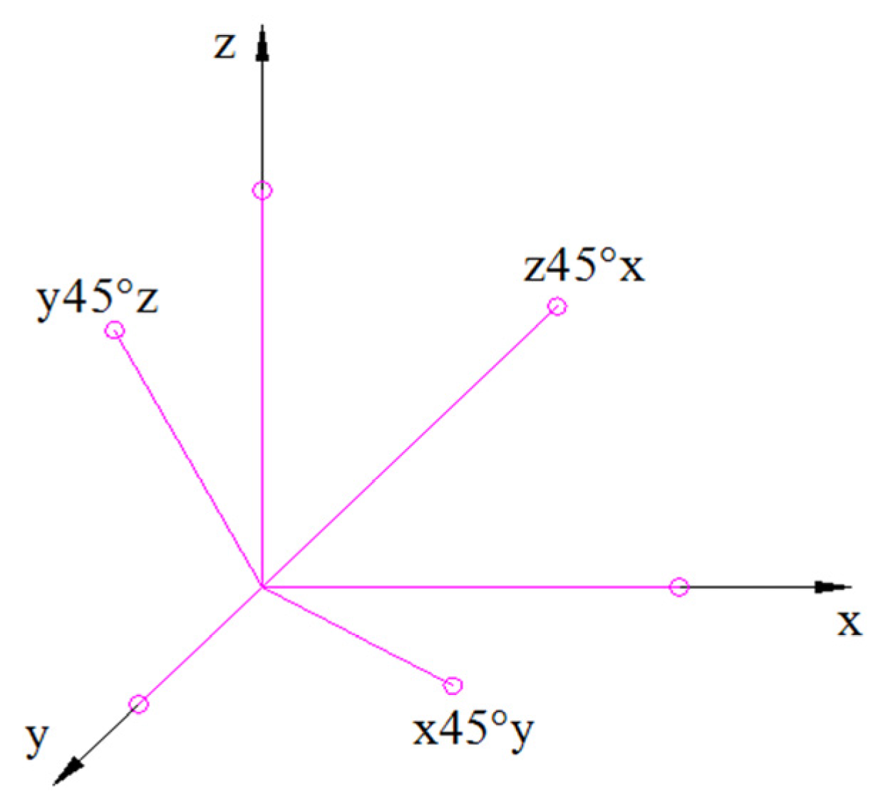
4.1.1. State of In-Situ Stress in Coal Seams

Underground, a coal seam is in a triaxial compressive stress state, where three principle stress components are usually unequal to each other. The vertical stress component σv is equal to the overlying rock weight in vertical orientation. There is a linear relationship between the major or intermediate principle stress and the seam burial depth. The in-situ stress analysis is assumed to obey the stress distribution rule that is suitable for Mainland China [28,29]. Thus, the principle stresses in Equation (1) can be obtained:
{ σ v = ρ H σ H = 6.7808 + 0.0216 H σ h = 2.2323 + 0.0182 H
where ρ is the average weight of overlying rock (kN/m3) and H is the burial depth of coal seam (m). The burial depth of Chinese coal seam usually ranges from 300 to 700 m. The overlying rock is mainly composed of mudstone and marlstone strata. Conventionally, the average weight of overlying strata is taken as 25 kN/m3. For simplicity, the Poisson ratio can be assumed as zero [13,21].

4.1.2. The Effect of Burial Depth on Borehole Cracking Initiation

In China, a coal seam is usually at a depth of less than 1000 m. The initial cracking pressure and location are plotted in Figure 9, where the values of α and β are set as 0°, 30°, 45°, 60° or 90°. It can be seen that the initiation pressure increases with the buried depth of coal seam, and boreholes are more likely to collapse at a smaller initiation pressure under the in-situ stress. Figure 10 shows the initiation direction is independent of the burial depth, and the cracks initiated along the inclination or strike if α and β are both at 0° or 90°. When α and β are both at 30°, 45° or 60°, the initiation locations are mainly distributed in the second or fourth quadrant of the polar coordinate, but it tends to shift their direction to coal seam inclination with the increase of burial depth.
Figure 9. Relationship between the initial cracking pressure and burial depth.
Energies 08 06977 g009
Figure 10. Relationship between the initial cracking location and burial depth.
Energies 08 06977 g010

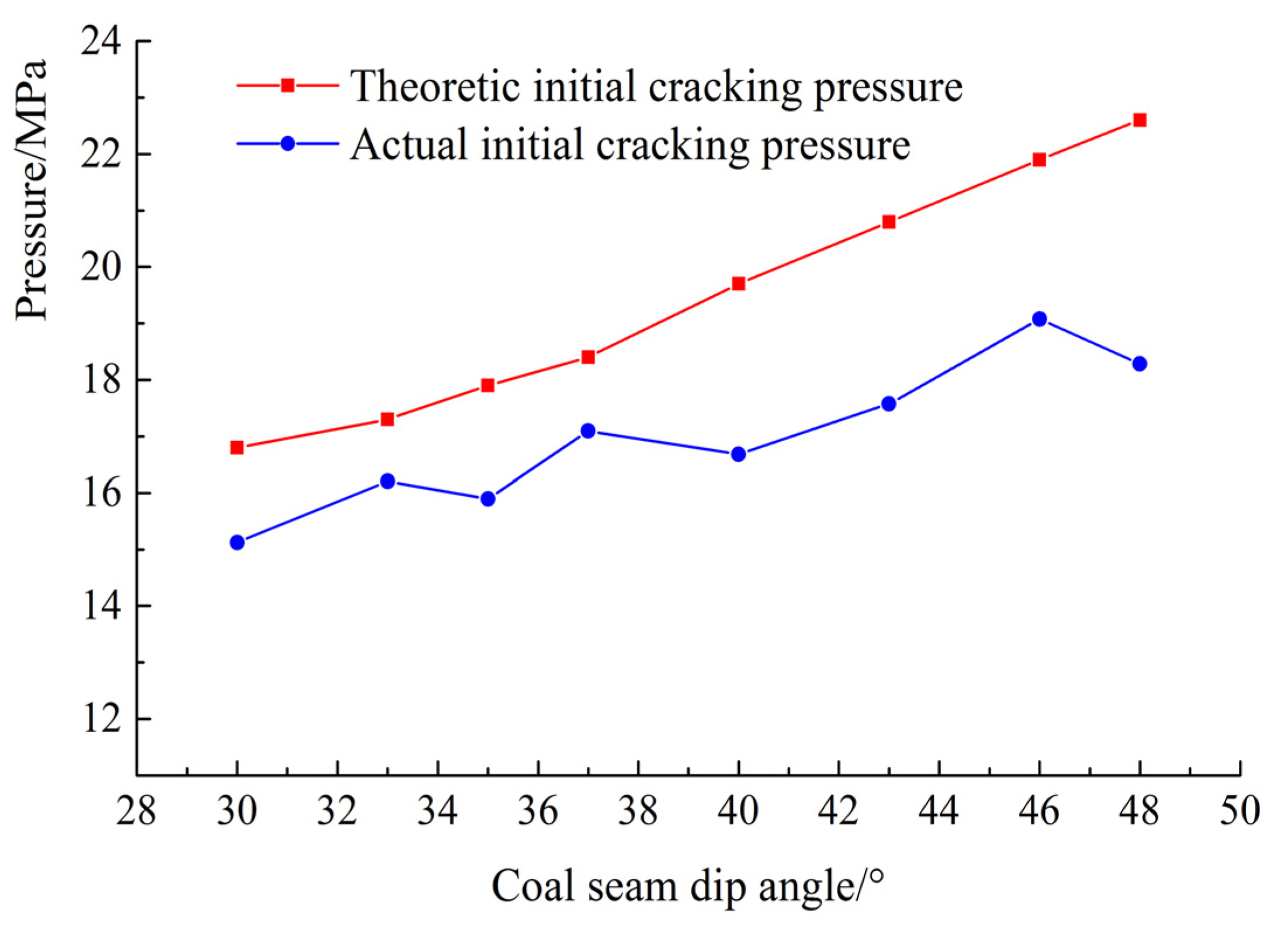
4.1.3. The Effect of the Coal Seam Dip Angle on Borehole Cracking Initiation

For coal seam at a depth of 500 m, its stress state can be calculated using Equation (10), where σv, σH, σh are 12.5, 17.58 and 11.33 MPa, respectively. Thus, when β is set at 0°, 30°, 45°, 60° and 90°, for different coal seam dip angle, the initiation pressure and initiation location changes as follows: the initiation pressure increases with coal seam dip angle as shown in Figure 11, and the cracks initiate along the inclination and strike of coal seam when β is set as 0° and 90°, respectively, as demonstrated in Figure 12. This trend is the same as that obtained with the increase in coal seam dip angle; when β is set as 30°, 45° or 60°, the cracks initiation locations are mainly distributed in the second or fourth quadrant of the polar coordinate. However, with the increase of coal seam dip angle, they shifted to the direction of coal seam strike, and the deflection speed increased during this process.
Figure 11. Relationship between the initial cracking pressure and coal seam dip angle.
Energies 08 06977 g011
Figure 12. Relationship between the initial cracking location and coal seam dip angle.
Energies 08 06977 g012

4.1.4. The Effect of the Stress Orientations on Boreholes Initiation

In this case, the same condition that the coal seam is buried at 500 m in depth is considered. When α is taken as 0°, 30°, 45°, 60° or 90°, for the different major principle stress azimuth, the initiation pressure and initiation location changes as follows.
As shown in Figure 13, when α is 0°, the initiation pressure remains invariable during the increase in the major principle stress azimuth. However, when α is taking the value of 30°, 45°, 60° and 90°, the initiation pressure decreases as the azimuth of major principle stress increases. It can be seen from Figure 14 that the cracks initiate along the direction of coal seam strike when α is 90°; when α is 0°, 30°, 45° and 60°, respectively, the initial cracking locations mainly occurred in the second or fourth quadrant of the polar coordinate, and shifted to direction of coal seam strike with the increase in azimuth angle. The deflection speed reduced in the process.
Figure 13. Relationship between the initial cracking pressure and the major principle stress azimuth angle.
Energies 08 06977 g013
Figure 14. Relationship between the initial cracking location and the major principle stress azimuth angle.
Energies 08 06977 g014

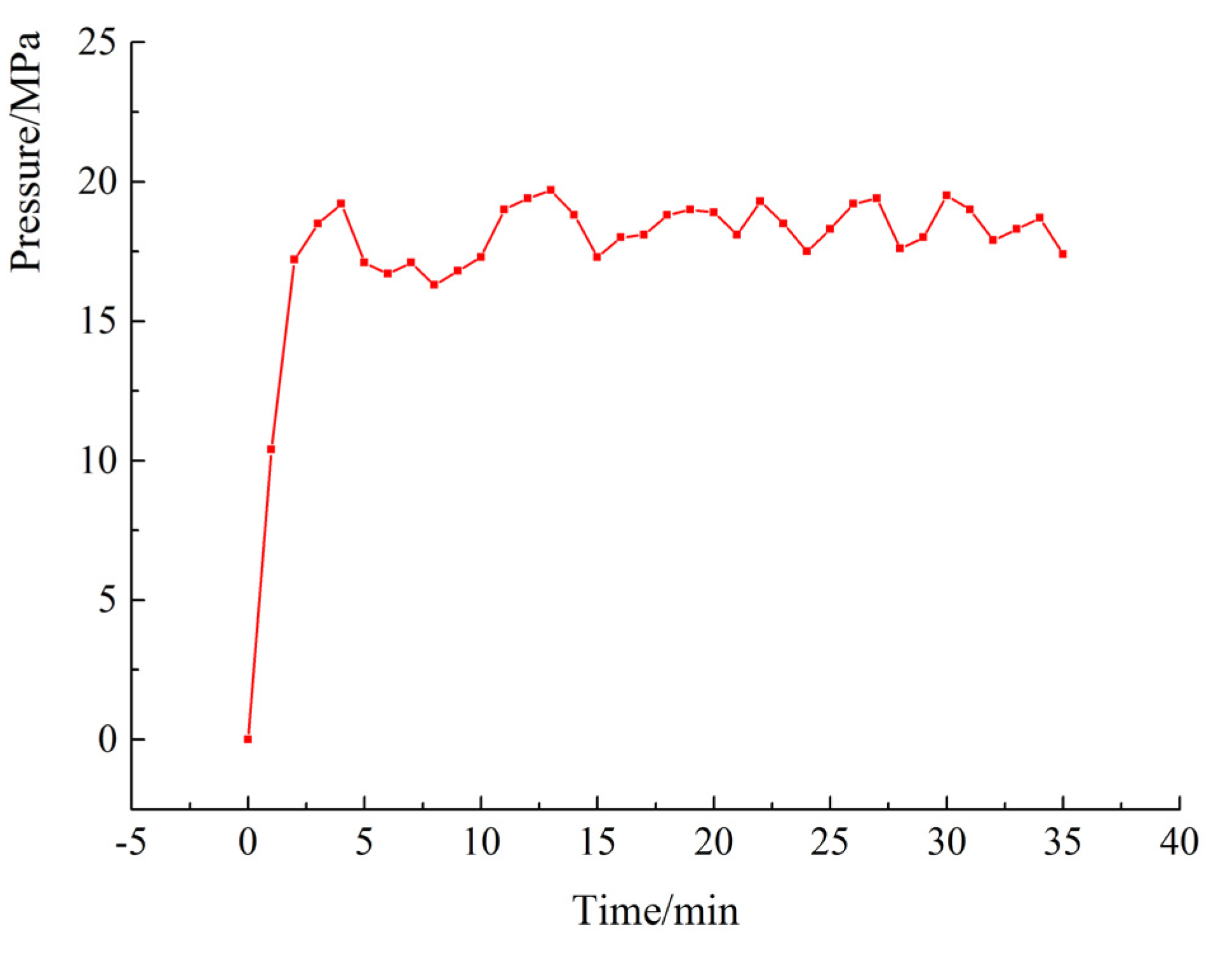
4.2. Field Validation and Discussion

Table 3 summarizes the test results of in-situ stress at field site. The intermediate principal stress σ2 and the vertical stress σv are considered to be equal for the small offset of σv in vertical direction. Due to the small offset between σH and σh in the horizontal plane, the major principal stress σ1 and minor principal stress σ3 are considered equal to the major horizontal principal stress σH and minor horizontal principal stress σh, respectively. Using in-situ stress test results and the developed mathematical model for initial cracking parameters and the condition of coal seams in fractured area, the theoretical initiation pressure of boreholes from No. 1# to No. 8# were calculated individually and summarized in Table 4.
Table 4. Theoretical initiation parameters of Nos. 1#–8# borehole.
Number1#2#3#4#5#6#7#8#
Initiation pressure/MPa16.817.317.918.419.720.821.922.6
Initiation location/°144143.5143.1142.7142141.2140.6139.7
Boreholes drilling and sealing were completed in Tonghua coalmine on 13–28 May 2013. From May 2013 to August 2013, the hydraulic fracturing were carried out in boreholes from No. 1# to No. 8# seriatim at ±0 m south main roadway of Tonghua coalmine. Figure 15 illustrates the pump pressure change in No. 1# borehole, during the fracturing process. Figure 16 shows the comparison between the theoretic initial cracking pressure and the initial cracking pump pressures. The points on the blue line in Figure 16 represent the initial cracking pump pressures of No. 1# to No. 8# borehole, respectively.
It can be seen from Figure 15 that the system pressure increased sharply at the beginning of the fracturing process, and then reduced when the cracks initiate. The decrease process of pump pressure is not the same as that during the oil and gas wells fracturing, but the repeated increase and decrease in the pressure can be observed. This can be explained by the reason that coal has a higher plasticity and more pores and cracks compared with rocks typically encountered during oil and gas well fracturing. Thus, the coal seam initial cracking pressure should be the first maximum pump pressure during fracturing. Then, the pump pressure of crack initiation for No. 1# to No. 8# borehole is shown in Figure 16. It can be seen that the pressure tends to increase with the coal seam dip angle, which is consistent with the theoretical prediction. However, the pump pressure of crack initiation is higher than that theoretical one. There maybe two reasons to explain this phenomenon:
(1)
The fracturing pump is far away from the borehole for the safety purpose and a certain amount of pressure is dissipated in the pipe line from the pump to borehole destination. This amount of pressure loss can be calculated using the following Equation [30]:
Δ p 1 = 59.7 Q 2 D 5 Re 0.25 L
where Δ p 1 is the pressure loss of the pipe line (MPa/m); Q is the average flow (L/min); D is the diameter of pipe line (mm), which is 32 mm; Re is the Reynolds number, taking 11165Q/D; and L is the distance between pump and fractured borehole (m), which is usually set as 500 m.
(2)
The gravity of water increases the actual initiation pressure due to the height difference between fractured borehole bottom and the discharged pump. This amount of pressure loss can be calculated from the following Equation:
Δ p 2 = ρ g Δ h
where Δ p 2 is the pressure loss caused by the gravity of water (MPa); ρ is the density of water (kg/m3); g is the gravitational acceleration (m/s2); and Δ h is the height difference (m), which can be calculated from Table 1.
Figure 15. Pressure change in the borehole.
Energies 08 06977 g015
Figure 16. Comparison between the theoretic initial cracking pressure and the initial cracking pump pressure.
Energies 08 06977 g016
Therefore, after deducting the pressure loss of the pipeline and the water weight, the actual initiation pressure is shown in Figure 17. The actual initial cracking pressure is lower than the theoretical one, the natural joints and fractures of coal seam may decrease the initiation pressure [31], and the properties of the rock and the fracturing fluid can also affect the pressure to initiate hydraulic fracture.
Figure 17. Comparison between the theoretic initial cracking pressure and the actual initial cracking pressure.
Energies 08 06977 g017
In this study, only the influences of in-situ stress and condition of coal seams on the initial cracking pressure were analyzed. To further reveal factors affecting the initial cracking pressure, the in-depth study will focus on the influence of rock properties and fracturing fluid on hydraulic fracturing process.

5. Conclusions

Using the maximum tensile stress criterion, this study analyzed the stress state around the boreholes during cross-measure hydraulic fracturing, and then developed a mathematical model for borehole wall initial cracking parameters. Finally, the influences of in-situ stress and coal seam dip angle on hydraulic fracturing initial pressure and locations in underground coalmines were investigated using the model. Field test data from Tonghua coalmine verified the proposed model. The results suggest that the initial cracking pressure increases with depth and coal seam dip angle, whereas it decreases with the increase in azimuth of major principle stress. This study also found that the initial cracking locations mainly occurred in the second and fourth quadrant in polar coordinate. With the increase in coal seam dip angle and azimuth of major principle stress, its direction shifted to strike of coal seam. The result of the field test is consistent with the rule that the initiation pressure increases with the coal seam dip angle, verifying the validity of the proposal mathematical model.

Acknowledgments

This study was financially supported by the National Science and Technology Major Projects of China under Grant No. 2011ZX05065, the National Natural Science Foundation of China (NSFC) under Grant No. 51374258, and Program for Changjiang Scholars and Innovative Research Team in University of China under Grant No. IRT13043.

Author Contributions

Yiyu Lu, Liang Cheng and Zhaolong Ge all contributed to developing the mathematical model, designing the experiments, and writing the paper; Binwei Xia, Qian Li and Jiufu Chen performed experiments.

Conflicts of Interest

The authors declare no conflict of interest.

References

  1. Dai, S.F.; Ren, D.Y.; Chou, C.L.; Finkelman, R.B.; Seredind, V.V.; Zhou, Y.P. Geochemistry of trace elements in Chinese coals: A review of abundances, genetic types, impacts on human health, and industrial utilization. Int. J. Coal Geol. 2012, 94, 3–21. [Google Scholar] [CrossRef]
  2. Shen, B.H.; Liu, J.Z.; Zhang, H. The technical measures of gas control in China coal mines. J. China Coal Soc. 2007, 32, 673–679. [Google Scholar]
  3. Yuan, L. Key technique to high efficiency and safe mining in highly gassy mining area with complex geologic condition. J. China Coal Soc. 2006, 31, 174–178. [Google Scholar]
  4. Lu, Y.Y.; Liu, Y.; Li, X.H.; Kang, Y. A new method of drilling long boreholes in low permeability coal by improving its permeability. Int. J. Coal Geol. 2010, 84, 94–102. [Google Scholar] [CrossRef]
  5. Karacan, C.Ö.; Diamond, W.P.; Schatzel, S.J. Numerical analysis of the influence of in-seam horizontal methane drainage boreholes on longwall face emission rates. Int. J. Coal Geol. 2007, 72, 94–102. [Google Scholar] [CrossRef]
  6. Klaus, N. Control of gas emissions in underground coal mines. Int. J. Coal Geol. 1998, 35, 57–82. [Google Scholar]
  7. Sun, D.F.; Chen, J.F.; Long, J.M.; Li, W.S.; Mei, X.D. Experimental study on high pressure hydraulic fracturing technology to uncover coal in cross-cut. Coal Sci. Technol. 2013, 41, 163–165. [Google Scholar]
  8. Hubbert, M.K.; Willis, D.G. Mechanics of hydraulic fracturing. Trans. Soc. Petrol. Eng. AIME 1957, 210, 153–166. [Google Scholar]
  9. Schmidt, D.R.; Zoback, M.D. Poroelasticity effects in the determination of minimum horizontal principal stress in hydraulic fracturing test—A proposed breakdown equation employing a modified effective stress relation for tensile failure. Int. J. Rock Mech. Min. Sci. 1989, 26, 499–506. [Google Scholar] [CrossRef]
  10. Zhang, X.; Jeffrey, R.G.; Bunger, A.P.; Thiercelin, M. Initiation and growth of a hydraulic fracture from a circular wellbore. Int. J. Rock Mech. Min. Sci. 2011, 48, 984–995. [Google Scholar] [CrossRef]
  11. Huang, J.; Griffiths, D.V.; Wong, S.W. In situ stress determination from inversion of hydraulic fracture data. Int. J. Rock Mech. Min. Sci. 2011, 48, 476–481. [Google Scholar] [CrossRef]
  12. Huang, J.; Griffiths, D.V.; Wong, S.W. Initiation pressure, location and orientation of hydraulic fracture. Int. J. Rock Mech. Min. Sci. 2012, 49, 59–67. [Google Scholar] [CrossRef]
  13. Chen, M.; Jin, Y.; Zhang, G.Q. Rock Mechanics of Petroleum Engineering; Science Press: Beijing, China, 2008; pp. 167–173. [Google Scholar]
  14. Wang, T.; Zhou, W.B.; Chen, J.H.; Xiao, X.; Li, Y.; Zhao, X.Y. Simulation of hydraulic fracturing using particle flow method and application in a coal mine. Int. J. Coal Geol. 2014, 121, 1–13. [Google Scholar] [CrossRef]
  15. Zhang, X.; Jeffrey, R.G.; Thiercelin, M. Deflection and propagation of fluid-driven fractures at frictional bedding interfaces: A numerical investigation. J. Struct. Geol. 2007, 29, 396–410. [Google Scholar] [CrossRef]
  16. Zhang, X.; Jeffrey, R.G.; Thiercelin, M. Escape of fluid-driven fractures from frictional bedding interfaces: A numerical study. J. Struct. Geol. 2008, 30, 478–490. [Google Scholar] [CrossRef]
  17. Li, X.Z.; Lin, B.Q.; Zhai, C.; Li, Q.G.; Ni, G.H. The mechanism of breaking coal and rock by pulsating pressure wave in single low permeability seam. J. China Coal Soc. 2013, 38, 918–923. [Google Scholar]
  18. Lian, Z.L.; Zhang, J.; Wang, X.X.; Wu, H.A.; Xue, B. Simulation study of characteristics of hydraulic fracturing propagation. Rock Soil Mech. 2009, 30, 169–174. [Google Scholar]
  19. Lin, H.X.; Du, C.Z. Experimental research on the quasi three-axis hydraulic fracturing of coal. J. China Coal Soc. 2011, 36, 1801–1805. [Google Scholar]
  20. Li, C.L.; Kong, X.Y. A theoretical study on rocks break down pressure calculation equation of fracturing process. Oil Drill. Prod. Technol. 2000, 22, 54–57. [Google Scholar]
  21. Hossain, M.M.; Rahman, M.K.; Rahman, S.S. Hydraulic fracture initiation and propagation: Roles of wellbore trajectory, perforation and stress regimes. J. Petrol. Sci. Eng. 2000, 27, 129–149. [Google Scholar] [CrossRef]
  22. Bradley, W.B. Failure of inclined borehole. J. Energ. Resour. Technol. 1979, 101, 233–239. [Google Scholar] [CrossRef]
  23. Aadnoy, B.S.; Rogaland, U.; Chenevert, M.E. Stability of Highly Inclined Boreholes. In Proceedings of the SPE/IADC Drilling Conference, New Orleans, LA, USA, 15–18 March 1987.
  24. Tan, C.P.; Willoughby, D.R. Critical Mud Weight and Risk Contour Plots for Designing Inclined Wells. In Proceedings of the 68th Annual Technical Conference and Exhibition of the Society of Petroleum Engineers, Houston, TX, USA, 3–6 October 1993.
  25. Ge, Z.L.; Mei, X.D.; Lu, Y.Y.; Xia, B.W.; Chen, J.F. Mechanical model and test study of sealed drilling for hydraulic fracturing in underground coal mines. Rock Soil Mech. 2014, 35, 1097–1103. [Google Scholar]
  26. Jiang, Y.D.; Xian, X.F.; Xu, J. Research on application of Kaiser effect of acoustic emission to measuring initial stress in rock mass. Rock Soil Mech. 2005, 26, 946–950. [Google Scholar]
  27. Khademian, Z.; Shahiar, K.; Gharouni, N.M. Developing an algorithm to estimate in situ stresses using a hybrid numerical method based on local stress measurement. Int. J. Rock Mech. Min. Sci. 2012, 55, 80–85. [Google Scholar] [CrossRef]
  28. Jing, F.; Sheng, Q.; Zhang, Y.H.; Luo, C.W.; Liu, Y.K. Research on distribution rule of shallow crustal geostress in China mainland. Chin. J. Rock Mech. Eng. 2007, 26, 2056–2062. (In Chinese) [Google Scholar]
  29. Zhao, D.A.; Chen, Z.M.; Cai, X.L.; Li, S.Y. Analysis of distribution rule of geostress in China. Chin. J. Rock Mech. Eng. 2007, 26, 1265–1211. (In Chinese) [Google Scholar]
  30. Thomas, J.L. Fluid Jet Technology: Fundamentals and Application; Water Jet Technology Association: St. Louis, MO, USA, 1995. [Google Scholar]
  31. Zhu, B.C.; Tang, S.H.; Yan, Z.F.; Zhang, J.Z. Effects of crustal stresses and natural fractures on fracture pressure of coal reservoirs. J. China Coal Soc. 2009, 34, 1199–1202. [Google Scholar]

