
Modeling on the Effect of Coal Loads on Kinetic Energy of Balls for Ball Mills

School of Control and Computer Engineering, North China Electric Power University, Beijing 102206, China
*
Author to whom correspondence should be addressed.
Energies 2015, 8(7), 6859-6880; https://doi.org/10.3390/en8076859
Submission received: 15 May 2015
/
Revised: 1 July 2015
/
Accepted: 2 July 2015
/
Published: 9 July 2015
(This article belongs to the Special Issue Recent Advances in Coal Combustion and Gasification)
Abstract
:This paper presents a solution for the detection and control of coal loads that is more accurate and convenient than those currently used. To date, no research has addressed the use of a grinding medium as the controlled parameter. To improve the accuracy of the coal load detection based on the kinetic energy of balls in a tubular ball mill, a Discrete Element Method (DEM) model for ball kinematics based on coal loads is proposed. The operating process for a ball mill and the ball motion, as influenced by the coal quality and the coal load, was analyzed carefully. The relationship between the operating efficiency of a coal pulverizing system, coal loads, and the balls’ kinetic energy was obtained. Origin and Matlab were utilized to draw the variation of parameters with increasing coal loads in the projectile and cascading motion states. The parameters include the balls’ real-time kinetic energy, the friction energy consumption, and the mill’s total work. Meanwhile, a method of balanced adjacent degree and a physical experiment were proposed to verify the considerable effect of the balls’ kinetic energy on coal loads. The model and experiment results indicate that a coal load control method based on the balls’ kinetic energy is therefore feasible for the optimized operation of a coal pulverizing system.
1. Introduction
Ball mills, which grind coal to a target size prior to boiler combustion, are important auxiliary equipment in thermal power plants. Their coal grinding efficiency is closely related to the economy of the power plant, as discussed by Masiuk, et al. [1]. The control requirement for a pulverizing system is to guarantee that the coal load in the ball mill is close to the optimum level. Therefore, accurately measuring and controlling the coal load of a ball mill is key to maintaining the proper boiler feed. Currently, the various detection methods include the differential pressure method, the vibration method, the noise method, the ultrasonic method, the power method and different combinations of these methods. In the differential pressure method, the coal load is expressed in terms of the pressure difference between the inflow and outflow of a ball mill, and the measuring precision is finite and determined by the air rate. The fundamentals of vibration method are to analyze the relationship between the vibration strength of the bearing and the coal load at a constant rotational speed of the ball mill. However, this method has poor linearity and low accuracy. In detecting the coal load, the noise method utilizes ball mill noise, which has poor anti-interference and large deviations due to the effect of environmental noise on the audio signals. The ultrasonic inspection method realizes coal detection by building relations in the sending-receiving interval between the ultrasonic sensor and the interface. The shortcomings of this method are a high system cost, demanding environmental requirements, and the lack of stability and reliability. In the power method, material levels are detected by the power transformation rule of the coal load. Nevertheless, the sensitivity of this method needs to be improved, and it may be difficult to estimate the coal load when the electric power of a ball mill decreases. The above mentioned methods cannot truthfully reflect the coal load in ball mills because they have many limitations and low accuracies [2,3].
The motion of the ball mill’s medium can directly influence the power consumption of grinding and is associated with the grinding mechanism [4,5]. Davis [6] and Lu, et al. [7] studied projectile motion in ball mills and established the ball’s motion equations by numerical modeling, and they developed a systematic theory for grinding coal. Ying [8] studied the influence of the mill’s rotation rate, the ball filling ratio, and many other factors on balls’ motion. Afterwards, many domestic and overseas scholars performed numerical modeling and developed theories of medium movement states, such as the two-phase movement theory [9,10,11]. Although there is already a considerable amount of research on the medium’s motion track and how the mill’s working parameters influence the medium’s motion in different distribution areas, there are only a few studies on using the grinding medium as a controlled parameter.
The above-mentioned findings and discussions reveal that there has not been a unified, rigorous and complete mathematical theory for a ball mill grinding process, and this theory lacks a more complete and accurate method for supervising and controlling the coal load. The research on improving the mill’s efficiency and lowering energy consumption has not provided breakthrough progress. The aim of this study is to obtain the relationship between the ball motion and coal loads and realize a better coal load control method based on the balls’ kinetic energy. To improve the performance of the coal load control method, a Discrete Element Method (DEM) is used to analyze the kinematics of the balls under the influence of the coal load. A method of balanced adjacent degree and a physical experiment further confirms that the balls’ kinetic energy can reflect the coal load more accurately. In this paper, the balls’ kinetic energy is utilized to detect and control the coal load, and this method avoids the influence of other factors and enhances the accuracy of coal detection.
2. Results and Discussion
The device architecture is described in detail in the Modeling Section. The force and boundary conditions for the balls and the coal are limited, and the accumulation of particles appears naturally. The kinetic energy, the friction energy consumption, and the mill’s total work for any location and size are conveniently determined in the ball and coal accumulation system. A three-dimensional image of the balls and the coal can be directly generated. PFC3D tracks every particle’s motion periodically and repeatedly, thus obtaining the motion of the overall granular mixtures.
Based on the PFC3D model, the initial values of the coal load are an arithmetic progression whose a(1) = 100, d = 200 and a(7) = 1300. The mill rotates uniformly in 5.6 rpm. The modeling simulation results for four revolutions of the cylinder are as follows:
2.1. Effects of Db = 0.03 m and N0.03 = 200
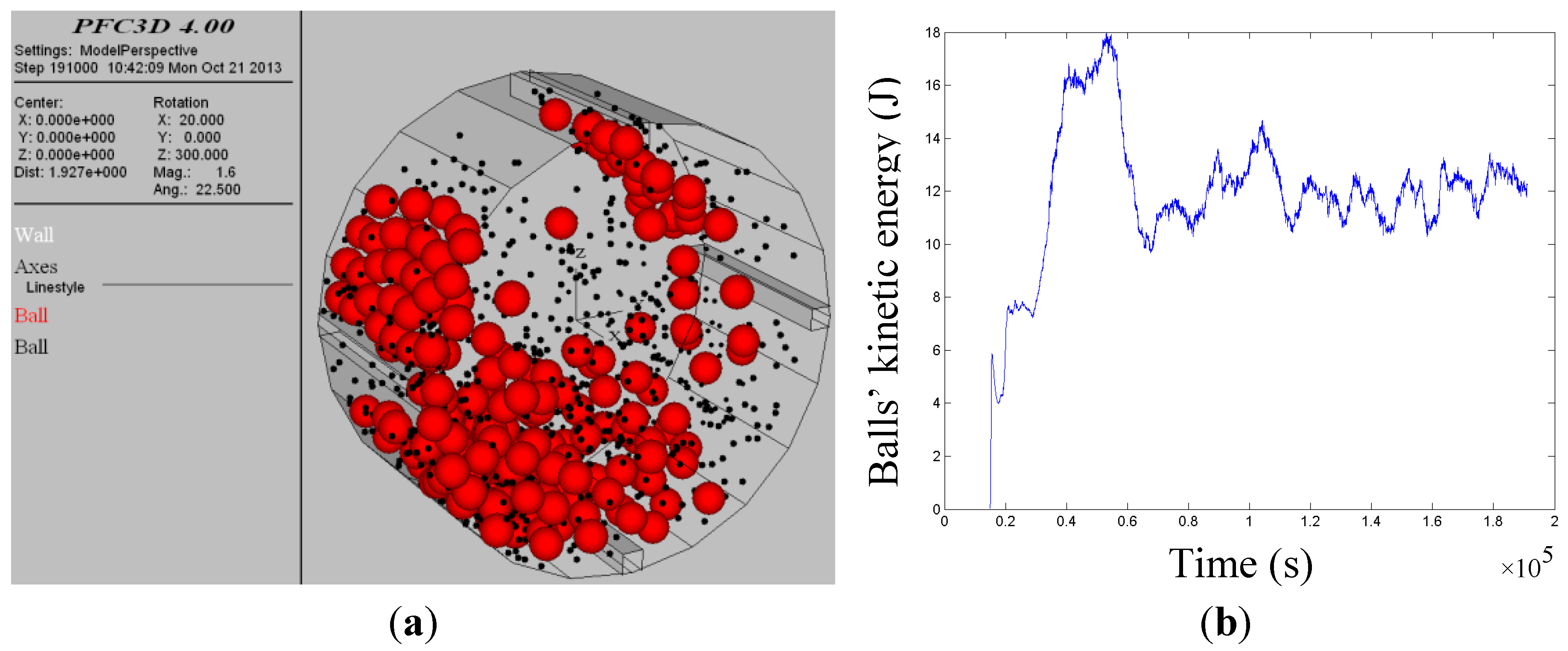
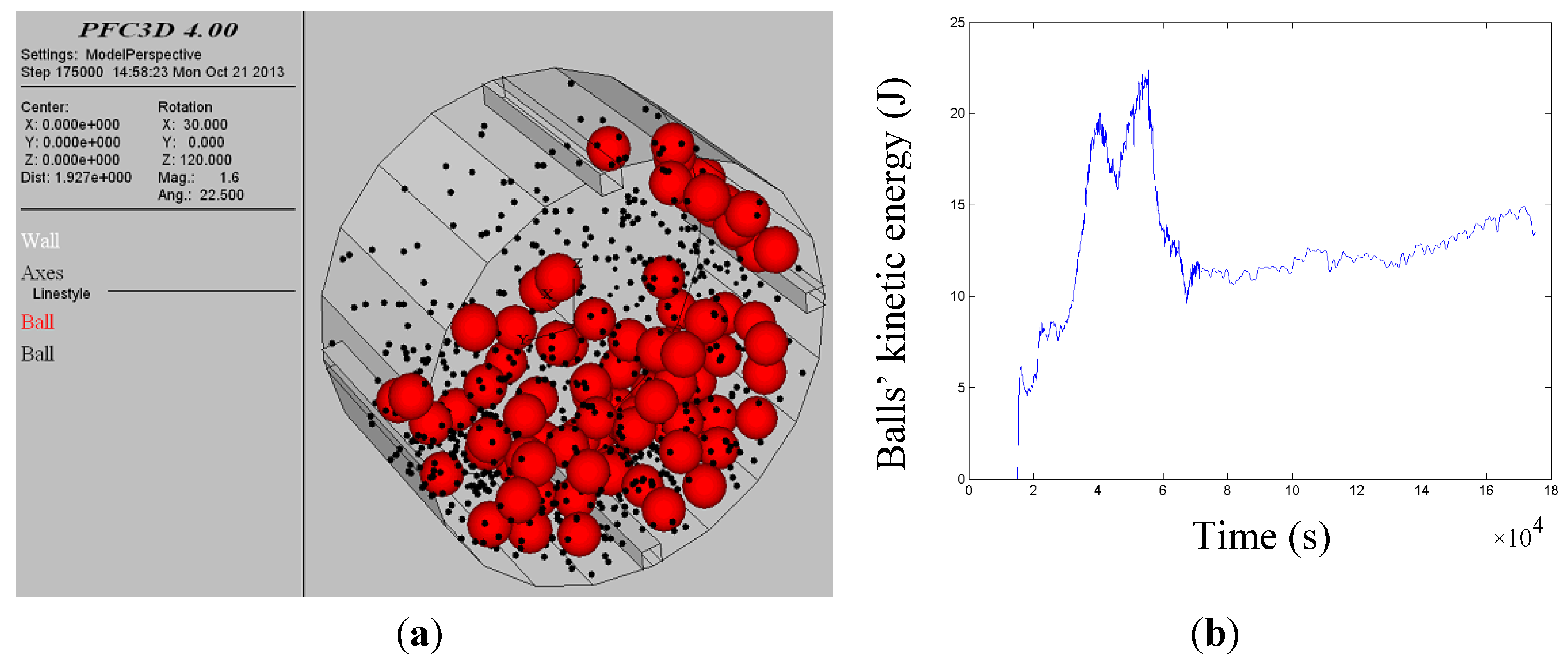
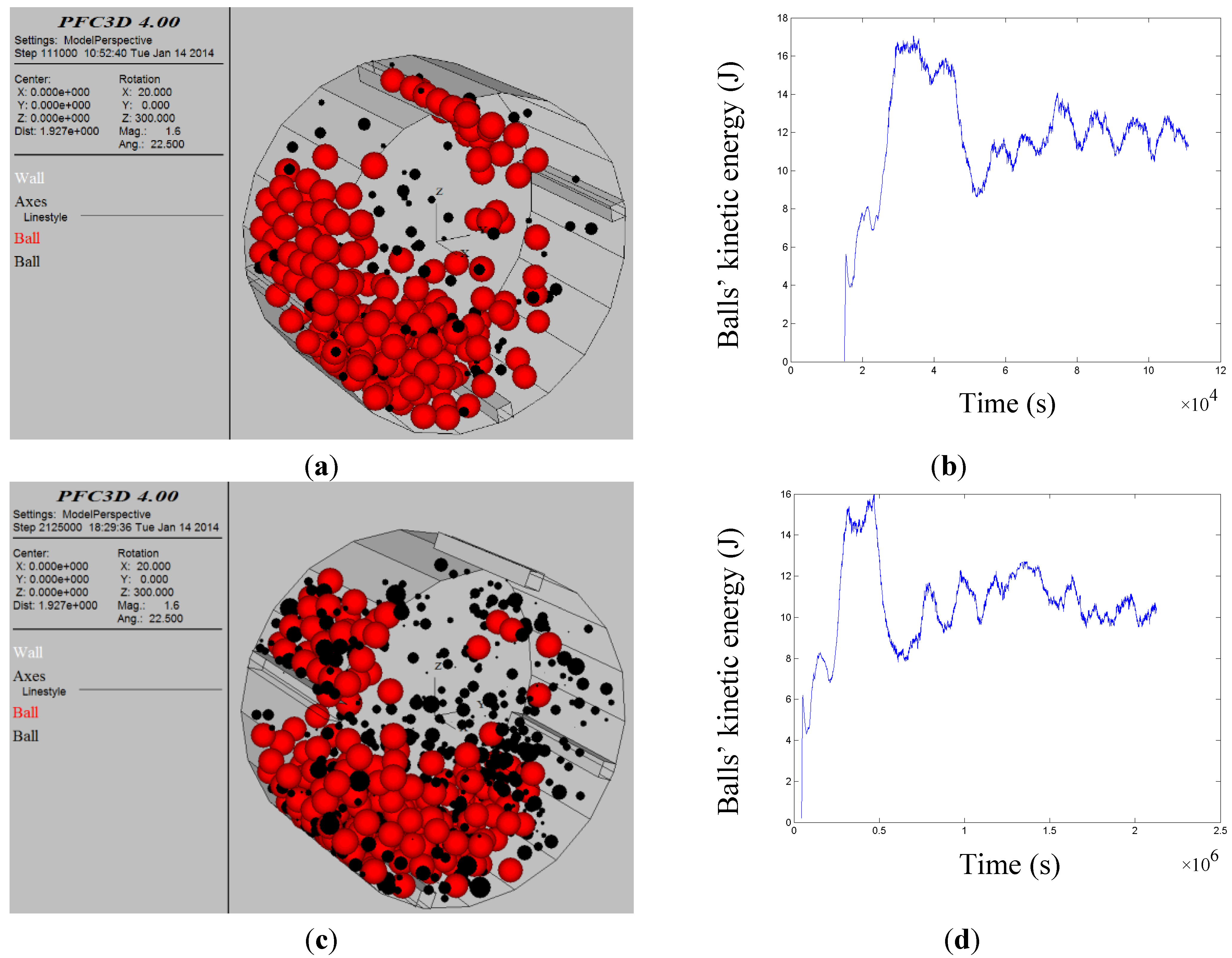
Figure 1a indicates the balls’ distribution and motion of the mill when it is running in a steady state after adding coal particles of Dm = 6 mm and Nm = 700. Figure 1b illustrates the real-time variation curve of the balls’ kinetic energy after the rotation of the cylinder, and it concludes that the balls’ kinetic energy reaches the obvious peak value when the projectile ball and the coal come to a certain value. Moreover, there exists a regular fluctuation of kinetic energy with the circulating rotation of the cylinder.
Figure 1.
(a) Simulation model of ball motion; (b) Real-time kinetic energy of balls.

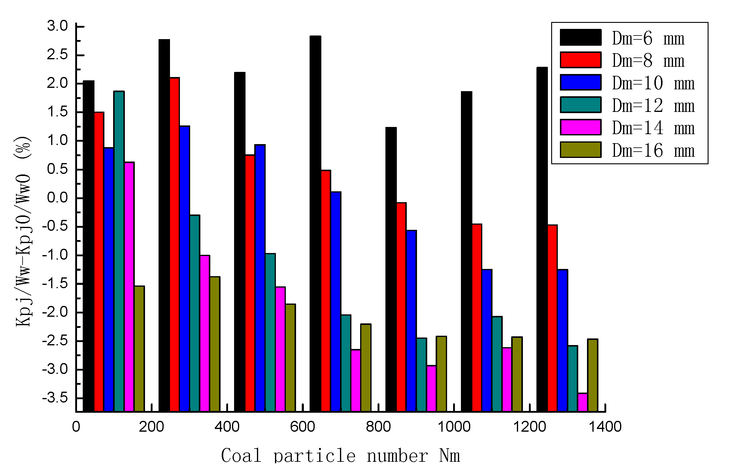
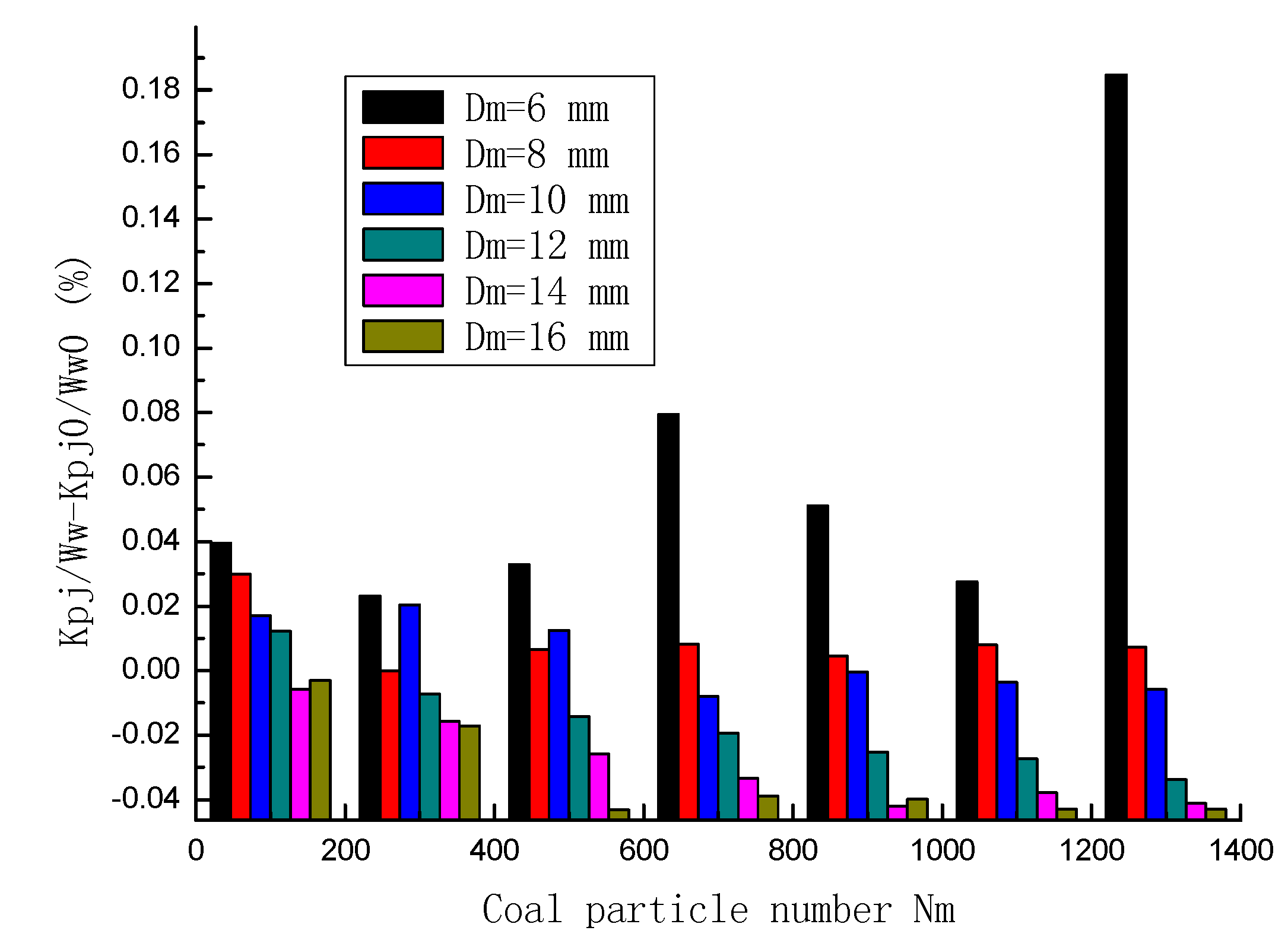
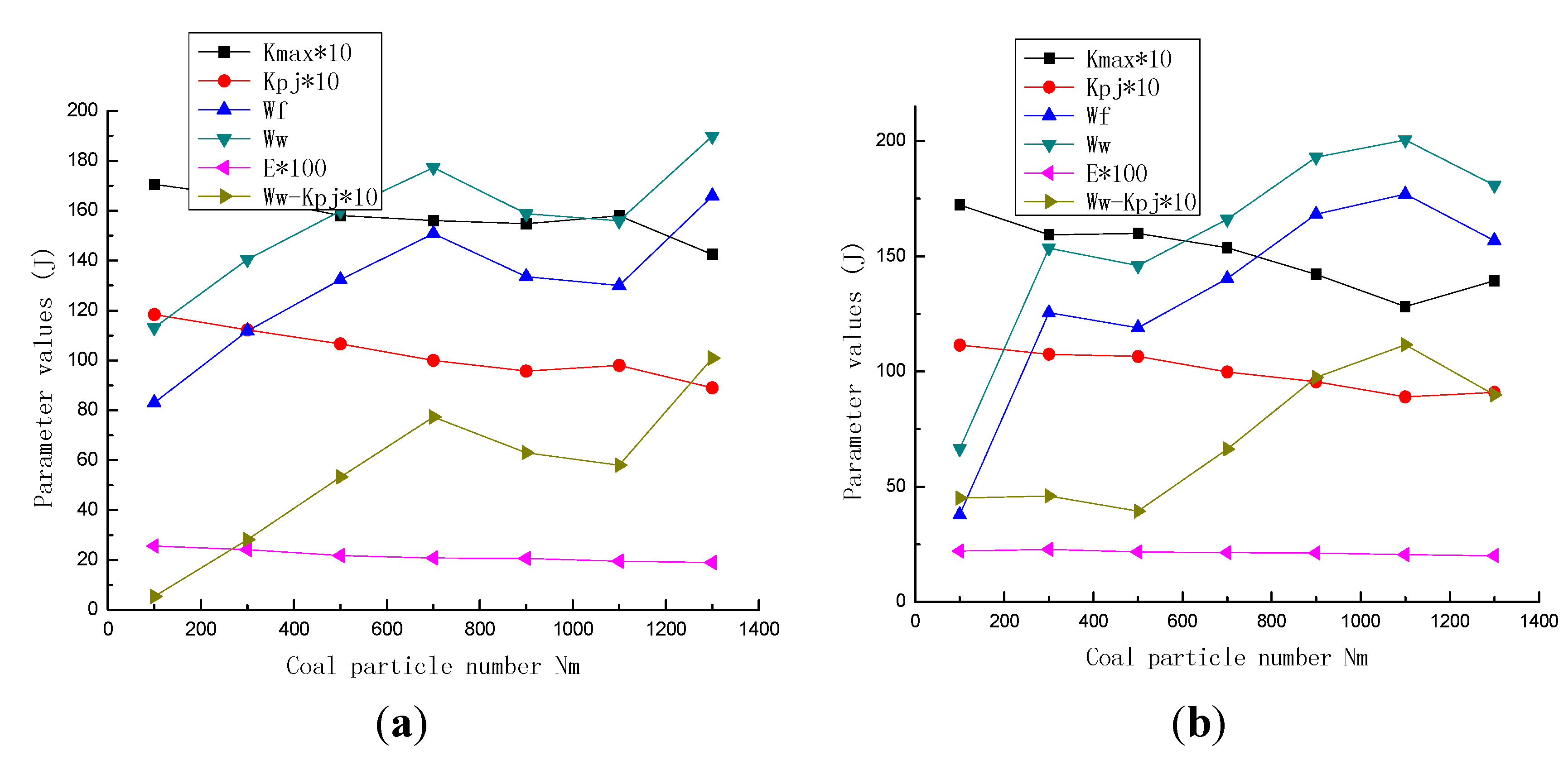
With increasing coal loads, the maximum and average value of the balls’ real-time kinetic energy, the energy consumption from sliding friction and the mill’s total work are shown in Figure 2 and Figure 3, where Kpj0/Ww0 represents the average value of the balls’ kinetic energy as a percentage of the mill’s total work when the mill rotates four revolutions without coal. In Figure 2, the balls’ work on the coal particles with different diameters is first increasing and then decreasing as the coal load increases. When Dm = 6 mm and Nm = 700, the balls’ kinetic energy accounts for 9.2831% of the mill’s total work, which is higher than the situation when there is no coal (6.4537%). That is, Kpj/Ww − Kpj0/Ww0 = 2.8294%. When Dm ≥ 12 mm, the increase of kinetic energy of the ball load becomes smaller and smaller as the coal load increases. When Dm = 16 mm, the projectile motion disappears, and the motion of the balls is mainly grinding and squeezing. Therefore, different ball mills and parameters are suitable for a limited range of coal diameters.
Figure 2.
Parameters of ball motion of Db = 0.03 m and N0.03 = 200 for coal particles with different diameters with increasing coal loads.
Figure 2.
Parameters of ball motion of Db = 0.03 m and N0.03 = 200 for coal particles with different diameters with increasing coal loads.

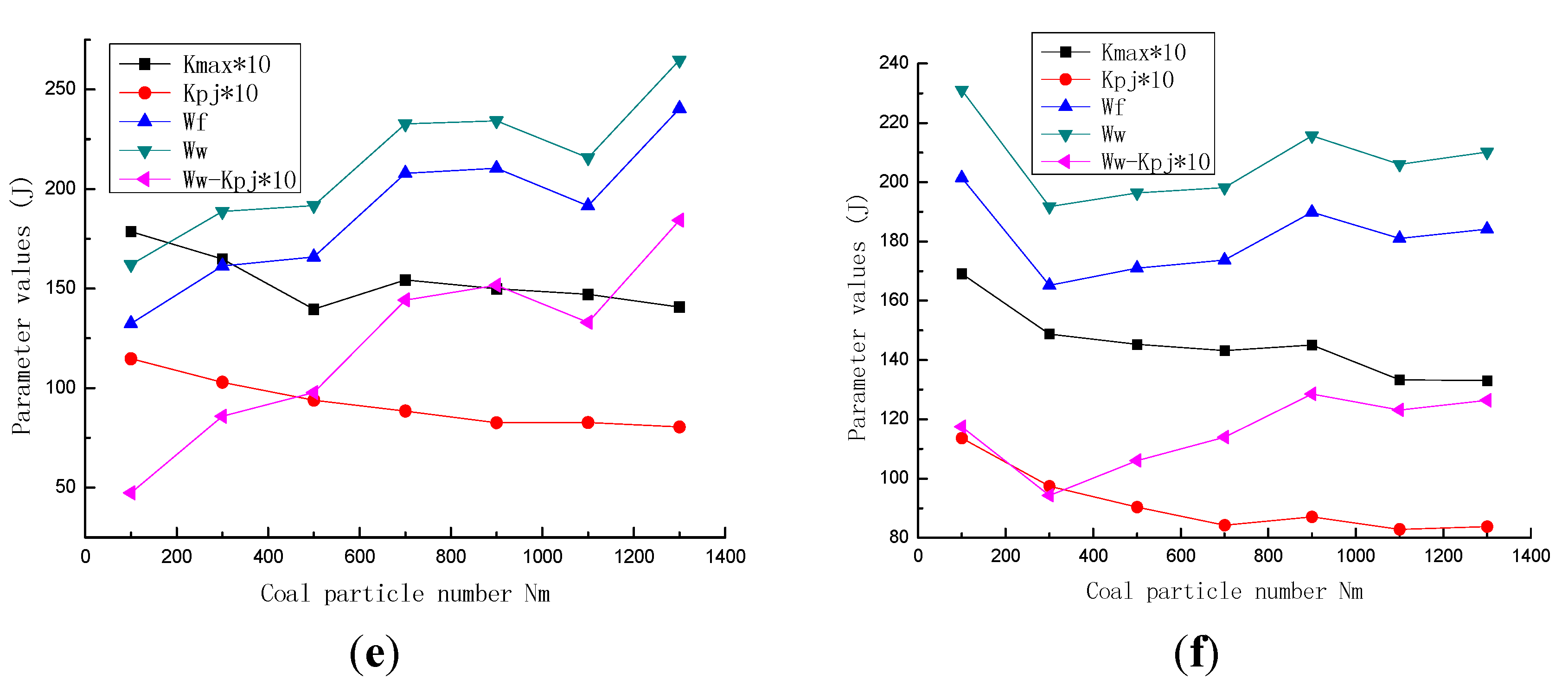
Figure 3.
(a) Dm = 6 mm; (b) Dm = 8 mm; (c) Dm = 10 mm; (d) Dm = 12 mm; (e) Dm = 14 mm; (f) Dm = 16 mm.
Figure 3.
(a) Dm = 6 mm; (b) Dm = 8 mm; (c) Dm = 10 mm; (d) Dm = 12 mm; (e) Dm = 14 mm; (f) Dm = 16 mm.


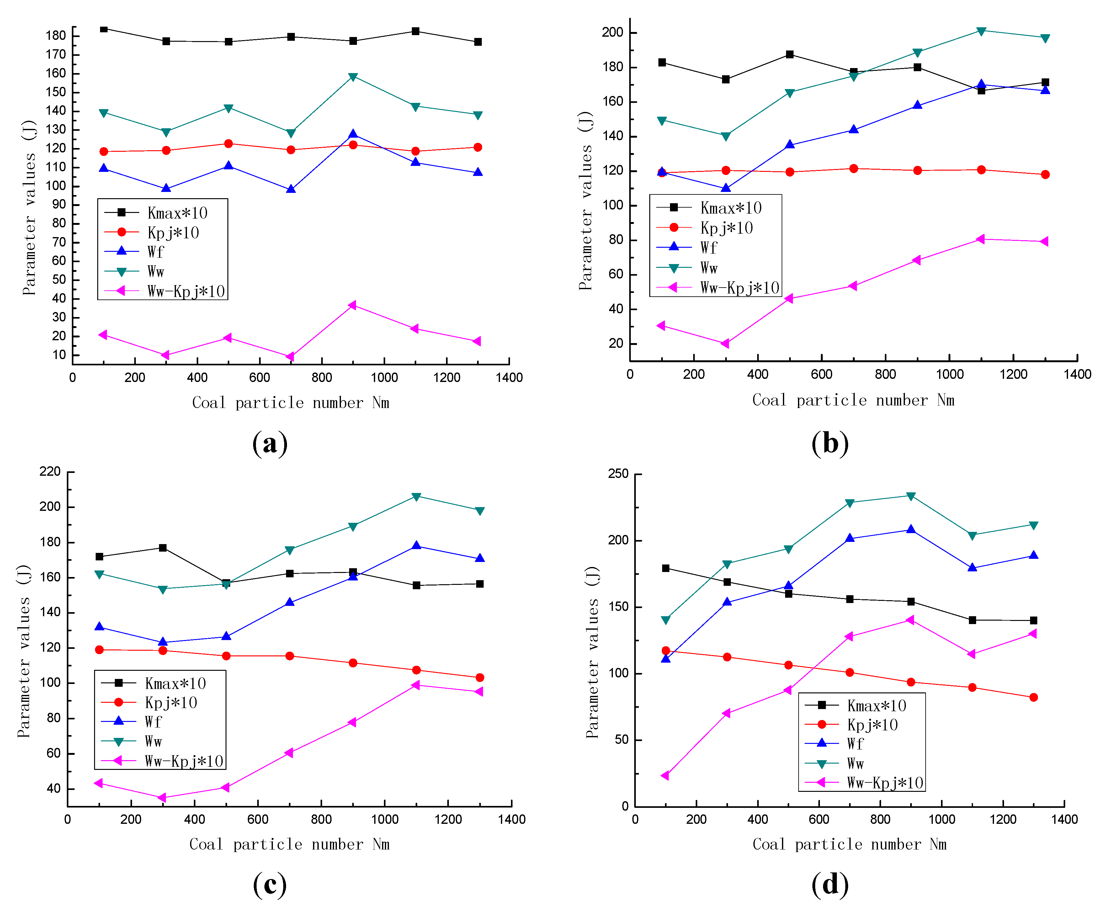
The maximum and average value of the balls’ kinetic energy for different coal particles’ diameters, energy consumption from the sliding friction and the mill’s total work with increasing coal loads are clearly demonstrated in Figure 3. To reflect the variation of the curve in the Figure 3, the maximum and average values of the balls are amplified by a factor of ten. The pink data points, shown in Figure 3, represents the difference between the mill’s total work and ten times the average value of the balls’ kinetic energy (Wn = Ww−Kpj*10). As a result, the variation of the friction energy consumption and the variation of the mill’s total work were fundamentally the same. When Wn was larger than its minimum, it increased gradually, and the mill’s total work rose while the balls’ kinetic energy remained almost the same. The minimum of the curve corresponded to the optimal coal load, which further indicated that when the coal load exceeded a certain value, both the mill’s useful work and the use ratio of the balls’ kinetic energy decreased. Therefore, the real-time kinetic energy of the ball motion closely relates to the coal load and the mill’s operational efficiency.
2.2. Effects of Db = 0.04 m and N0.04 = 86
Figure 4a demonstrates the PFC3D distribution and the motion of coal particles of Dm = 6 mm and Nm = 700 corresponds to the 86 balls inputted, which reached their maximum kinetic energy when the mill cylinder rotated in steady state. Figure 4b demonstrates the real-time variation curve of the balls’ kinetic energy in Figure 4a after the mill rotates. Figure 5 and Figure 6 demonstrate the maximum and average value of the balls’ kinetic energy, the friction energy consumption and the mill’s total work with increasing coal loads.
Figure 4.
(a) Simulation model of ball motion; (b) Real-time kinetic energy of balls.

Figure 5.
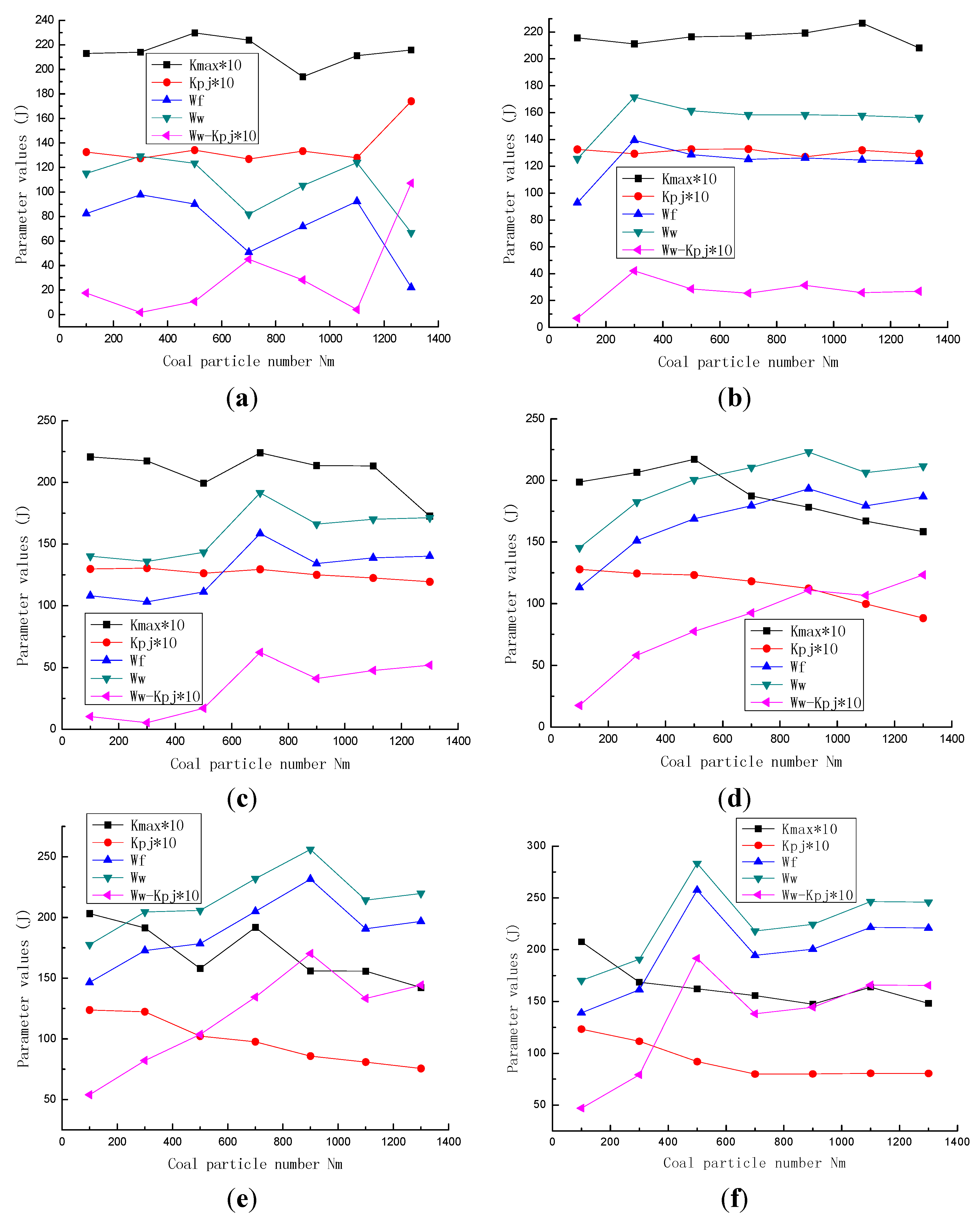
Parameters of ball motion of Db = 0.04 m and N0.04 = 86 for coal particles with different diameters with increasing coal loads.
Figure 5.
Parameters of ball motion of Db = 0.04 m and N0.04 = 86 for coal particles with different diameters with increasing coal loads.

In the comparison between Figure 2, Figure 3, Figure 5 and Figure 6, increasing ball diameter by 0.01 m, the growth rate of the balls’ kinetic energy reduces with increasing coal particles’ diameters. However, when Dm ≤ 12 mm, the balls’ kinetic energy increases in the beginning and then decreases with increasing coal loads. The larger the coal particle’s diameter is, the less the optimal coal load corresponds to the maximum of the balls’ kinetic energy. Wn increases with increasing coal loads but has a minimum point. Therefore, the motion space of balls inside the mill is limited. When the coal load exceeds the optimum value, the balls’ impact strength gradually decreases, and their grinding effect on coal loads plays a leading role. Because it is influenced by the ball’s diameter and the coal particle’s diameter, the optimal coal load possesses different functional values [12,13].
Figure 6.
(a) Dm = 6 mm; (b) Dm = 8 mm; (c) Dm = 10 mm; (d) Dm = 12 mm; (e) Dm = 14 mm; (f) Dm = 16 mm.
Figure 6.
(a) Dm = 6 mm; (b) Dm = 8 mm; (c) Dm = 10 mm; (d) Dm = 12 mm; (e) Dm = 14 mm; (f) Dm = 16 mm.

2.3. Effects of Coal Size Distribution
Coal particles are of different sizes during the grinding process of a ball mill. To further simulate actual operation conditions of a ball mill, PFC3D models were respectively conducted on coal particles (6–16 mm) with a uniform distribution and a Gaussian distribution. The random numbers were drawn from coal particle number (such as Nm = 100) with coal particle diameters between 6 mm and 16 mm. In addition, the balls’ strain energy was researched. Figure 7a shows the PFC3D motion of the coal particles with Nm = 100 with a uniform distribution corresponding to the balls of Db = 0.03 m and N0.03 = 200, which reached their maximum kinetic energy when the mill was running in a steady state. Figure 7c shows the PFC3D motion of the coal particle Gaussian distribution with Nm = 500 under otherwise identical conditions. Figure 7b,d demonstrate the real-time variation curve of the balls’ kinetic energies in Figure 5a,c, respectively. Figure 8 and Figure 9 show the maximum and average value of the balls’ kinetic energy, the strain energy, the friction energy consumption and the mill’s total work with increasing coal loads.
These results show that strain energy of the balls was much smaller than the balls’ kinetic energy and the mill’s total work. Consequently, the strain energy of the balls was amplified a hundred times to reflect the variation of the parameter values in the figure. Balls were less affected by the kinetic energy of the cylinder rotation movement. Assuming the dynamic and temperature effects were not considered in the process of deformation, the work performed by the mill’s total work on the balls would be all stored in the coal in the form of strain and stress, and the work would be transformed into strain energy. The balls’ energy was almost all utilized to impact coal particles.
Figure 7.
(a) Simulation model of ball motion with uniform distribution; (b) Real-time kinetic energy of balls with uniform distribution; (c) Simulation model of ball motion with Gaussian distribution; (d) Real-time kinetic energy of balls with Gaussian distribution.
Figure 7.
(a) Simulation model of ball motion with uniform distribution; (b) Real-time kinetic energy of balls with uniform distribution; (c) Simulation model of ball motion with Gaussian distribution; (d) Real-time kinetic energy of balls with Gaussian distribution.

Figure 8.
Parameters of ball motion with coal particle size distribution with increasing coal loads.
Figure 8.
Parameters of ball motion with coal particle size distribution with increasing coal loads.
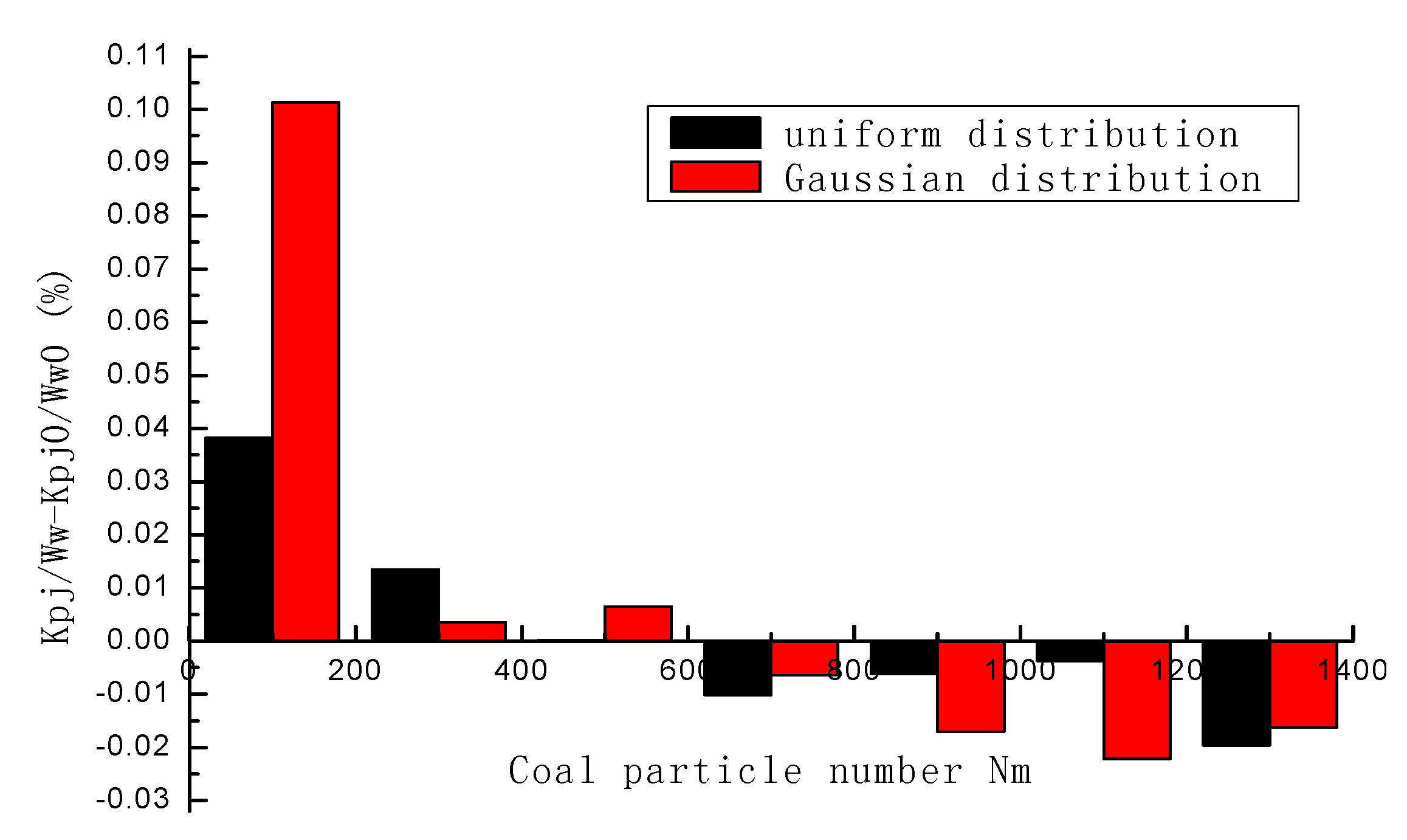
In Figure 1, Figure 4 and Figure 7, balls’ kinetic energy gradually reached its maximum, the impact strength of balls on coal loads is highest, the use ratio of balls is also highest, and the maximum useful work of the ball mill is done to obtain the qualified pulverized coal. Therefore, the projectile motion is a ball’s optimal motion state, the mill obtains the optimal coal load, which corresponds to the mill’s highest grinding efficiency. In Figure 2 and Figure 5, when the coal particles’ diameter and coal load are proper, the average value of the balls’ kinetic energy as a percentage of the mill’s total work gradually increased and then decreased in comparison with the situation when there was no coal. In Figure 3 and Figure 8, when the coal particles’ diameter is proper and the coal load increased, the difference between the mill’s total work and balls’ work on the coal experienced a minimum point and then increased. It is obtained that the balls and coal in the mill were going through a cascading motion, a projectile motion of several balls, a projectile motion of most of the balls, and a circular motion of almost all balls, respectively. In addition, the use ratio of the balls’ kinetic energy increased first and then decreased, and the mill’s efficiency likewise increased first and then decreased. In the comparison between Figure 2, Figure 3, Figure 8 and Figure 9, with increasing coal loads, the increasing range of the energy consumption of the friction and the mill’s total work for coal particle diameter with a uniform distribution and a Gaussian distribution was larger than for a situation with coal particles of equal size. The use ratio of the balls’ kinetic energy similarly increased in the beginning and then decreased with increasing coal loads. In conclusion, the balls’ real-time kinetic energy can indicate the mill’s coal load in a more precise way, and the mill obtains the optimal coal load when the balls reach a maximum kinetic energy, corresponding to the highest grinding efficiency. The energy consumption of the friction and the mill’s total work further indicate the use ratio of the balls’ impact force, thus demonstrating the mill’s grinding efficiency in indirect ways.
Figure 9.
(a) Coal particle uniform distribution; (b) Coal particle Gaussian distribution.

2.4. Ball Kinematics
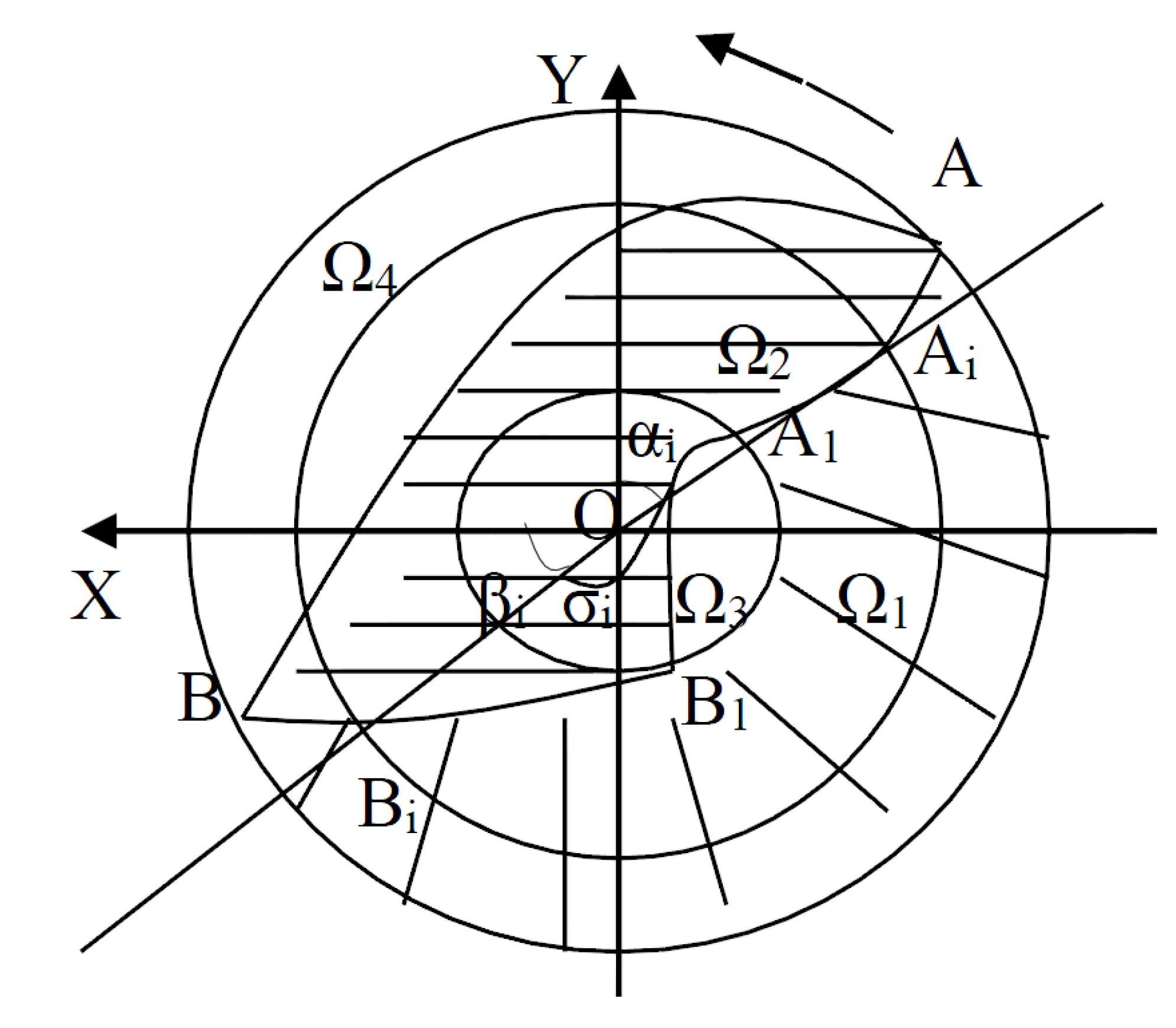
The coal load inside the mill is a significant factor in influencing ball motion. Figure 10 is the spatial distribution diagram describing that when the mill is rotating uniformly around a center axle O, the balls inside the mill would realize different motion with increasing coal loads. Where,
- Ω1 is the area where the balls undergo circular motions or cascades. When the coal load inside the mill is small or even empty, the possibility of collisions among the balls is larger. The friction force among the balls, the coal, and the mill’s liner is enhanced, and they are mainly affected by grinding in this area, and the friction force is enhanced, thus leading to unnecessary abrasion of the balls and liner and low grinding efficiency.
- Ω2 is the projectile motion area. When the coal load is normal and not exceeding the dropping point B of the balls’ outermost layer, the motion between the balls and the coal in the underneath area is mainly a striking motion. Therefore, this motion realizes a periodic collision between the balls and the coal, and it has a high efficiency.
Figure 10.
Distribution diagram of ball motion.

Suppose that the volume of all the moving balls is Ω = Ω1 + Ω2, L is the mill’s effective length, R is the distance between a ball regarded as a particle and the center of the ball mill, and the ball filling ratio Ψ = Ω/(πR2L) is the ratio of the balls’ loose volume and the mill’s effective volume. For the ball in the ith layer, σi is its central angle, αi is the included angle between OAi, which is the line that connects the mill’s center and the departure point, and the positive vertical axis Y. βi is the included angle between OBi, which is the line that connects the point of dropping and the center of the mill, and the positive horizontal axis X. According to the arc length computational formula, we can infer that dΩ1 = πRiLσi/180°dRi. The integration of the radius between the outermost layer R and the innermost layer R1 is:
And we can obtain that:
where σi = 270° − αi − βi = 360° − 4αi, i = 1,2, ···.
- 3.
- In the area around the mill’s center region Ω3, the balls’ circular motion and projectile motion are blended. Because space is limited, grinding and impact effect is weak.
- 4.
- In the empty area Ω4, balls do not move or undergo circular motion. When the coal load inside the mill is excessive, it would waste energy and cause operational troubles because the balls’ moving space is limited, and the balls are relatively still relative to the mill [14].
2.5. Verification of Parameter Correlation
2.5.1. Correlation Degree and Balance Degree Method
The correlation degree combined with the balance degree is utilized to verify that the balls’ kinetic energy is applicable for the control of the coal load in a ball mill. Correlation degree is a measure of the correlation degree of the factor variation trends between two systems with the increase of time or other variables. We judge the correlation degree between the reference data sequence and the comparison data sequence according to the geometrical relation and similarity of the generated data curves. The more approximate the variation trends of curves are, the bigger the correlation degree of the corresponding sequence is, and vice versa.
The reference data sequence reflects the behavioral characteristics of system,
the comparison data sequence affects the factors of system performance,
the absolute difference between and :
and the correlation coefficient of and :
Among all sequences, and are the maximum and minimum absolute difference, generally with . The distinguishing coefficient is . The correlation degree between the reference data sequence and the comparison data sequence is calculated by the following formula [15]:
To reduce the association tendency of local points, the balance degree is further adopted to measure and compare the correlation degree of the data sequence’s correlation coefficient series [16,17]. Supposing the correlation coefficient series of the jth comparison data sequence and the ith reference data sequence is , then the correlation coefficient distribution map is
where . We can define the following equation based on Equation (8):
The above equation is the correlation coefficient’s entropy of the jth comparison data sequence and the ith reference data sequence, and the balance degree is (10):
where is expressed as Ln(sequence number), and it is the largest entropy in the jth comparison data sequence. Thus, the balanced adjacent degree is:
where .
The correlation degree between each comparison data sequence and reference data sequence is ordered by the balance adjacent degree. Finally, we can determine the relationship between the comparison parameter and the reference parameter, and obtain the effective theory, which is based on the meaning of parameters.
2.5.2. Correlation Analysis of the Coal Load and Balls’ Kinetic Energy
From the DEM simulation’s results, analysis of the ball motion with increasing coal particles with different diameters clearly demonstrates that there exists a close relationship between the coal load and the balls’ real-time kinetic energy in the operational process of a ball mill. According to the above study, a balanced adjacent degree between the coal load and the balls’ kinetic energy is proposed.
The coal load in modeling data was selected as the reference data sequence, while other parameters, such as the balls’ kinetic energy, the energy consumption from sliding friction and the mill’s total work, were comparison data sequences. Ba1(Xi,Xj) represents the balance degree between the coal load and other parameters when Db = 0.03 m when the balls possess optimal projectile motion. Ba2(Xi,Xj) represents the balance degree between the coal load and other parameters when Db = 0.04 m and when the balls possess optimal projectile motion. The results in Table 1 show that every parameter’s balanced adjacent degree exceeds 0.6, and every parameter’s sensitivity to the variation of the coal load was high. While the balanced adjacent degree between the balls’ kinetic energy and the coal load was slightly higher than the energy consumption from sliding friction and the mill’s total work, it could better explain the coal load and reflect the working efficiency.

| Parameters Balanced adjacent degree | Kmax | Kpj | Wf | Ww |
|---|---|---|---|---|
| Ba1(Xi,Xj) | 0.6920 | 0.6936 | 0.6926 | 0.6929 |
| Ba2(Xi,Xj) | 0.6946 | 0.6948 | 0.6916 | 0.6926 |
3. Experimental Verification
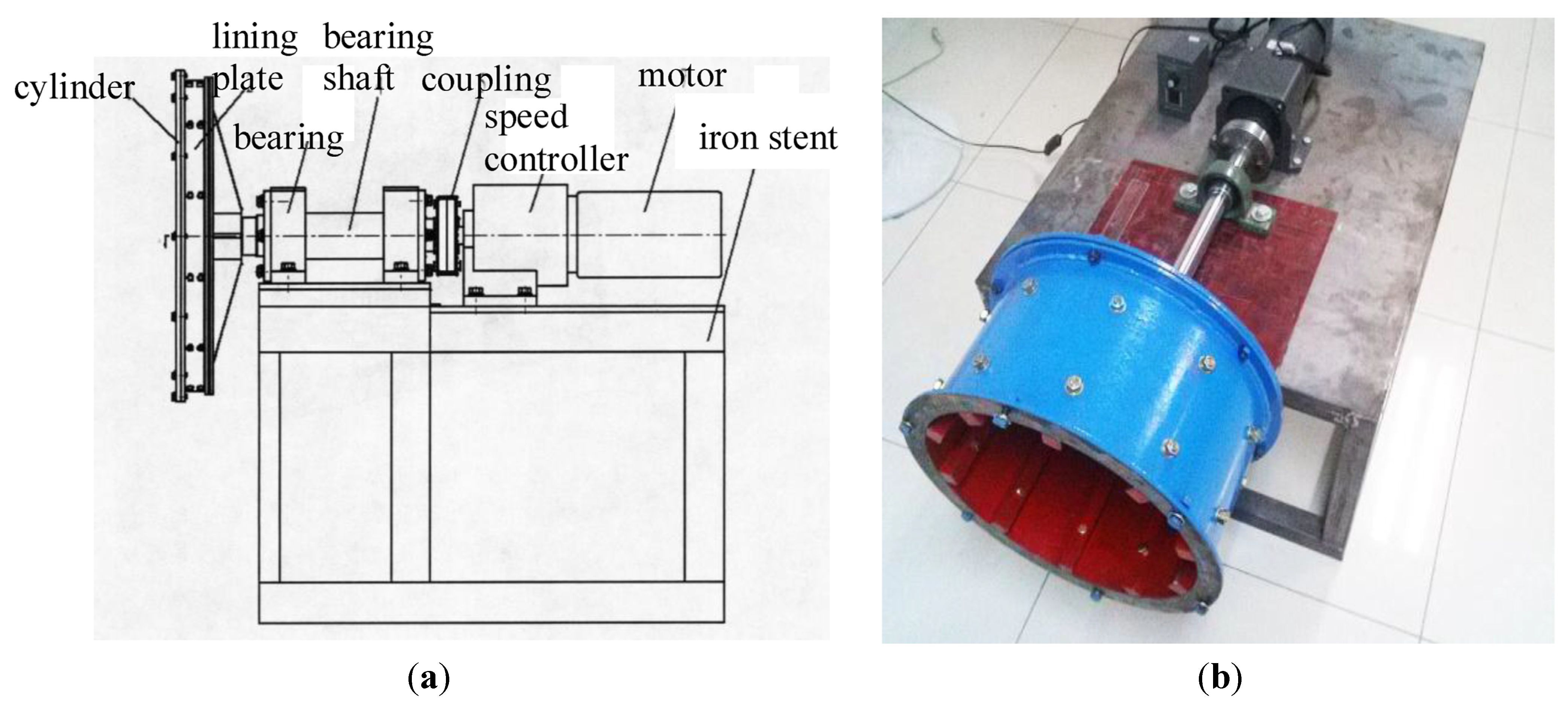
3.1. Experimental Apparatus
The practical ball motion is very complicated. The validity of the DEM model for ball kinematics with increasing coal loads is estimated by practical experiments. The experimental apparatus is shown schematically in Figure 11. It is a ball mill whose standard is Ø0.36 m × 0.2 m. The rough rubber lining plates are connected to 8 × 2 screw holes on the cylinder wall, which can change the number of lining plates. The electronic speed controller controls the working speed of the mill. An iron stent reduces vibration and increases the stability by connecting the bearing part with boards. The front cover and back cover are made up of thick flange and ribbed flange respectively. The front window glass and the mill cylinder are fixed by the front cover, and the middle rubber cradle is connected to avoid the damage of the front window. The diameter of balls is Db = 0.008 m, and the bulk density is ρ = 4.9 t/m3. Coal particles are replaced with the polypropylene plastic particles (EPP) in the experiment, which is similar to coal in physical characteristics, aiming at reducing the wear and tear of the mill cylinder and guaranteeing the visibility of the front glass window. Their bulk density is ρm = 0.75 t/m3, the rotation rate is Φ = 75% and the optimum ball filling ratio is Ψzj = 40%. Ψm is coal filling ratio. It is assumed that the ball filling ratio in the experiment satisfies that the balls can move in cascading or projectile motion.
Figure 11.
(a) General schematic drawing of experimental apparatus; (b) Ball mill physical experiment.
Figure 11.
(a) General schematic drawing of experimental apparatus; (b) Ball mill physical experiment.

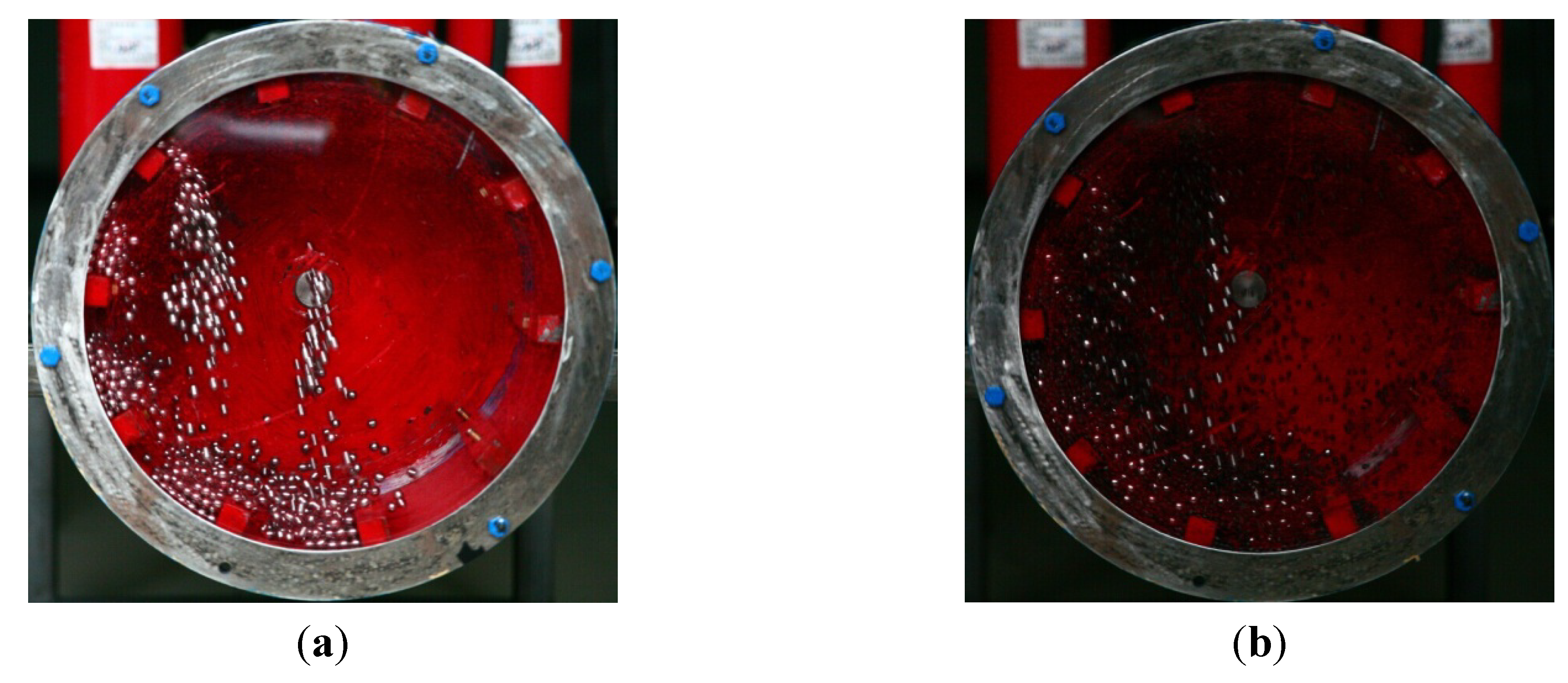
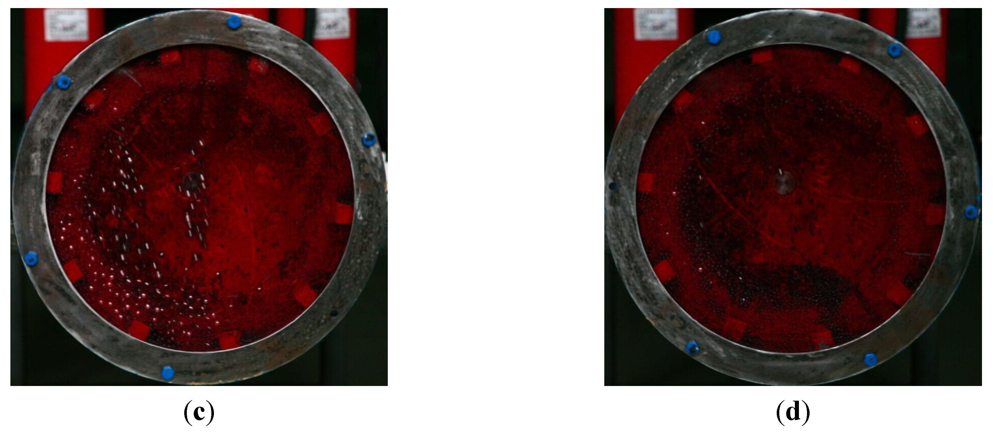
Based on the optimized configuration of the above operating parameters, the physical model of a ball mill was established. A high-speed camera was adopted to record the real-time variation of kinetic energy of balls and coal loads, the parameters are as follows: the camera body is CANON EOS 5D, 12.8 million pixels; the lens is CANON EF50MM, F1.4; the shutter speed is 1/256 S and the focal length is 105 mm. The initial values of the coal load are arithmetic progression whose a(1) = 10%, a(2) = 20% and a(3) = 50%. The mill rotates uniformly at 20 rpm. The physical experiment results are shown in Figure 12.
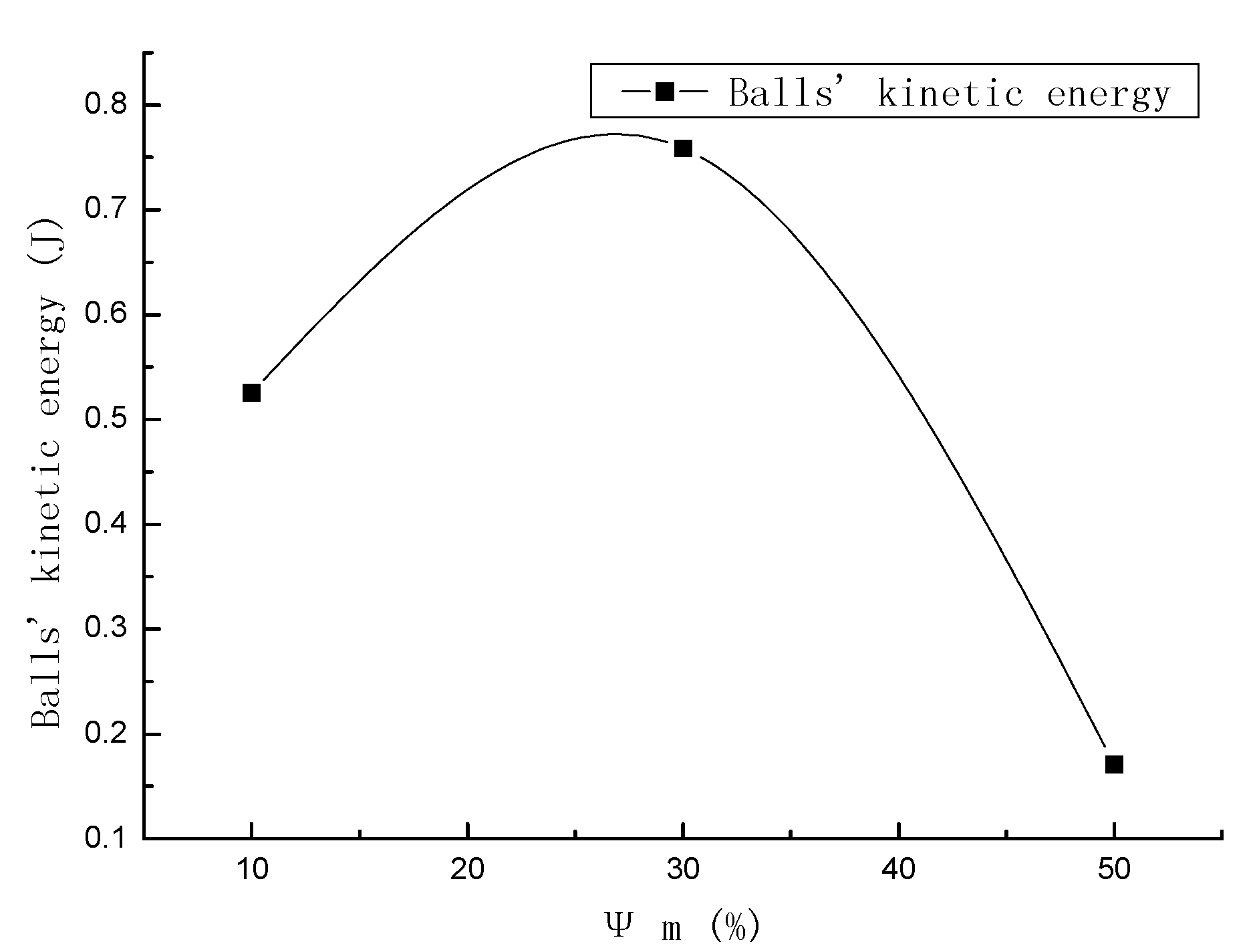
The use ratio of balls’ kinetic energy is performed by impacting and grinding coal loads. When Ψm >30%, the number of the projectile balls tend to decrease with increasing coal loads. When Ψm = 50%, the motion space of balls inside the mill is limited, balls’ impact strength gradually decreases and the grinding plays a leading role. It concludes that the projectile motion reaches the obvious peak point when the balls and coal loads come to a certain value. Therefore, ensuring the optimal motion state of balls is significant to the coal pulverizing efficiency for limited coal loads.
Figure 12.
(a) The motion state of balls without coal loads; (b) The motion state of balls with 10% coal loads; (c) The motion state of balls with 30% coal loads; (d) The motion state of balls with 50% coal loads.
Figure 12.
(a) The motion state of balls without coal loads; (b) The motion state of balls with 10% coal loads; (c) The motion state of balls with 30% coal loads; (d) The motion state of balls with 50% coal loads.

3.2. Experimental Results
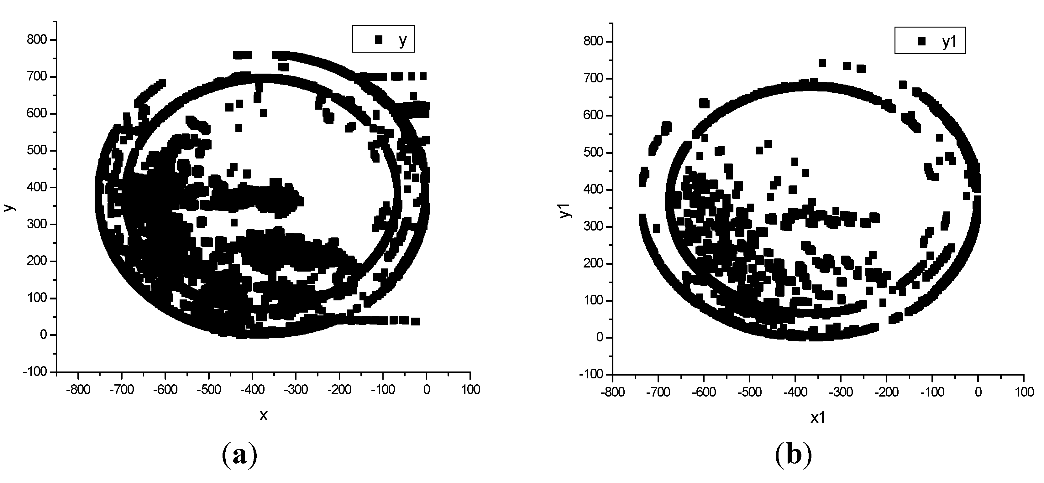
The position data of the balls and coal loads are shown in Figure 13 when the ball mill was running in a steady state. It further indicates that the ball motion is closely related to coal loads on equal conditions. In the process balls and coal loads in the mill are going through the cascading motion, the projectile motion of several balls and the one of most balls, their kinetic energy gradually reached its maximum. The projectile motion is the balls’ optimal motion state and it corresponds to mill’s highest grinding efficiency. However, balls do not move or undergo circular motion and the kinetic energy of balls decreased due to excess coal loads and the limited space.
Figure 13.
(a) The scatterplot of ball motion without coal loads; (b) The scatterplot of ball motion with 10% coal loads; (c) The scatterplot of ball motion with 30% coal loads; (d) The scatterplot of ball motion with 50% coal loads.
Figure 13.
(a) The scatterplot of ball motion without coal loads; (b) The scatterplot of ball motion with 10% coal loads; (c) The scatterplot of ball motion with 30% coal loads; (d) The scatterplot of ball motion with 50% coal loads.

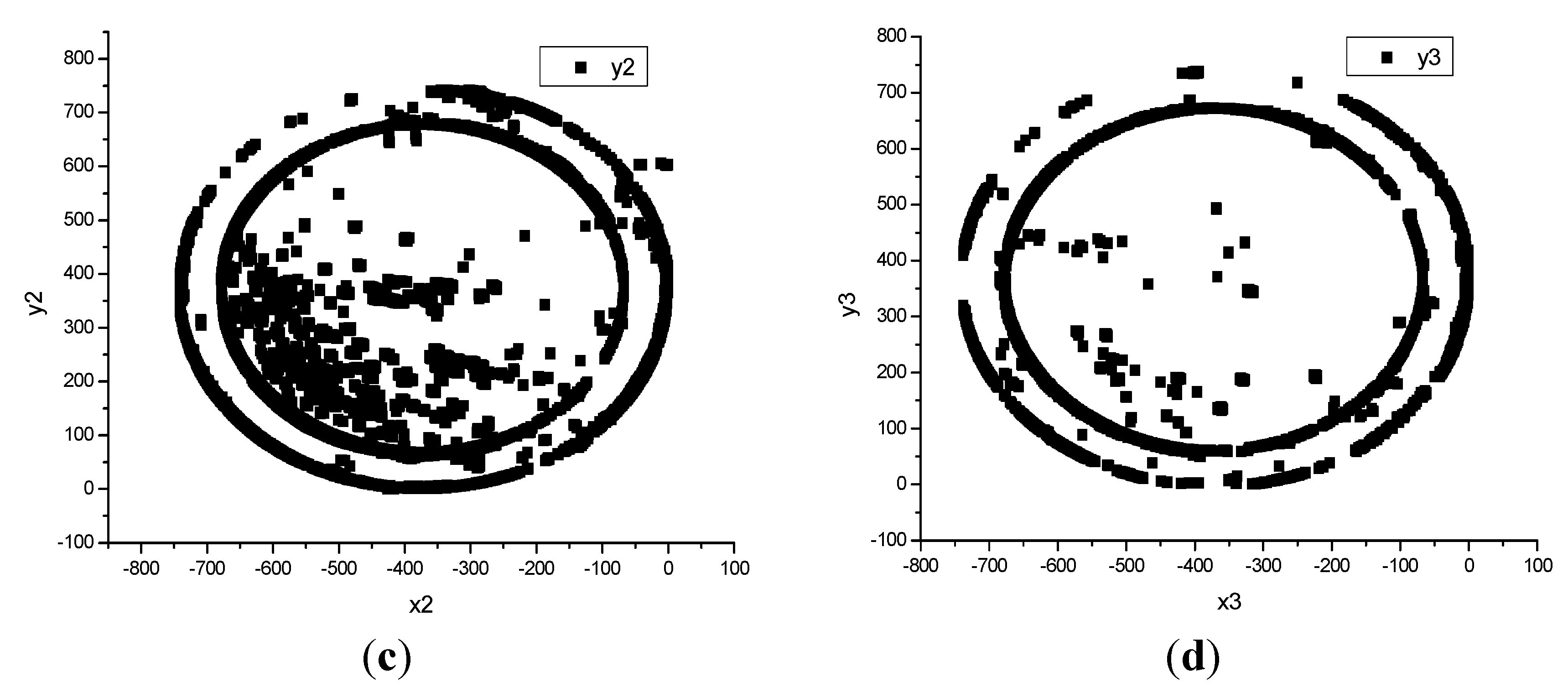
Figure 14 demonstrates the variation of balls’ kinetic energy with the coal loads based on the ball mill physical experiment. It is indicated that the more impact energy balls obtain in the projectile motion state, the higher the grinding efficiency is. The speed sensor and the torque will be utilized to measure the balls’ motion speed and the mill’ torque, and the relevant experimental study will be further designed in the future.
Figure 14.
Balls’ kinetic energy with increasing coal loads.
4. Modeling Section
A 0.4 m diameter by 1.2 m long ball mill with steel liner plates was modeled by a cylinder with special material characteristics according to the ball mill’s performance. The cylinder’s boundary was truncated into the 1/6 of the initial 1.2 m long. Balls and the coal inside the mill were modeled by spherical discrete elements of certain material characteristics and size. The balls’ diameters were Db = 0.03 m and Db = 0.04 m, and their bulk density was ρgq = 4.9 t/m3. The coal particles’ diameters are Dm = 6, 8, 10, 12, 14, 16 mm, and their bulk density was ρm = 0.75 t/m3. In a particle and contact model, a “ball-ball” contact and a “ball-wall” contact were affected by the contact force. The parameters with the most influence on the contact force were the stiffness, the damping, and the friction factor. The stiffness represented the stress resistance of balls to elastic deformation, the friction factor affected the power consumption of ball mills, and the damping main influenced the accumulation process and the course of energy dissipation [18]. Some properties of other parameters for the model are given in Table 2, which combines the operating characteristics of a ball mill with different performance properties of the materials. The rotation rate Φ, the ratio of the working speed to the critical speed of the mill, was selected as Φ = 80%. With the parameters optimized by the estimate method for experiments, the ball mill model was established by setting the parameters related to the external appearance of ball mills, which included a mill cylinder and cylinder walls.
| Model Parameters | Parameter Values |
|---|---|
| Friction factor(ball-ball) | 0.142 |
| Normal stiffness(ball-ball)/(N/m) | 2.0 × 10⁵ |
| Shear stiffness(ball-ball)/(N/m) | 2.0 × 10⁵ |
| Friction factor(ball-wall) | 0.189 |
| Normal stiffness(ball-wall)/(N/m) | 4.0 × 10⁵ |
| Shear stiffness(ball-wall)/(N/m) | 3.0 × 10⁵ |
| Ball’s density/(kg/m3) | 7.8 × 10³ |
| Normal damping | 0.3 |
| Tangential damping | 0.3 |
DEM is a numerical computation method for discontinuous medium mechanics and is used for solving and analyzing granular material’s equations of motion and kinetic parameters [19,20,21]. DEM separates granular mixtures to the set of discrete units, and the units themselves have certain geometrical, physical, and chemical properties. The medium motion is controlled by Newton’s second law, and it can be iteratively solved by dynamic or static relaxation method, which describes the whole medium’s law of motion by observing all units’ motion and location.
The particle i’s equation of motion according to Newton’s second law is as follows:
where , are respectively particle i’s accelerated velocity and angular acceleration, , are respectively particle i’s quality and rotational inertia, , are respectively the joint force and joint moment of force where the particle is in the center of mass. Central difference method is always used to do numerical integration for Equation (12), and it could obtain the updated speed which is expressed by the intermediate point of two iterative time steps, which is as follows:
where , are respectively particle i’s velocity and angular velocity, is time step, N is corresponding to time t. By integrating the Equation (13), we can get the Equation (14) which is with respect to displacement:
where , are respectively particle i’s displacement and angular displacement in this equation. Therefore we can compute the new force according to particle’s new value of displacement, and it satisfies the relationship of force-displacement. It tracks every particle’s motion periodically and repeatedly at any time, thus obtaining the motion of the overall granular mixtures. Fundamental assumptions are very important prerequisites for DEM analysis. The fundamental assumptions of this study are as follows:
- (1)
- The particle unit is regarded as a rigid body and a sphere.
- (2)
- Contacts happen over a tiny area, which is a point contact. There exists the maximum stress strength of contact-bonded model in the contact place.
- (3)
- The contact is a flexible contact. It allows a certain overlap, which is tiny in comparison with the particle size in the contact area, and it relates to contact force.
- (4)
- The time step is small. Any unit disturbance from indirect contact should be avoided, and the velocity as well as the accelerated velocity of any time step is constant.
DEM is used to simulate the ball mill with the optimized working parameters [22,23], and it records the real-time modeling simulation data of the balls’ kinetic energy by directly observing the ball motion when the mill’s coal load is different. The DEM model analyzes the ball kinematics with increasing coal loads under different parameter conditions.
Recently [24,25] PFC3D was used to simulate the motion and interaction between the balls and the coal by DEM. The pulverized coal with dry hot air is discharged and coal particles are added simultaneously, which is a process of dynamic equilibrium. The balls inside the mill are discontinuous, and the PFC3D model, which is based on a command driving mode, is good at processing discontinuous problems because it can demonstrate ball motion in a natural way, as discussed by Geng, et al. [26]. The PFC3D model uses an explicit difference algorithm and the theory of discrete element simulation to calculate the balls’ kinetic energy for coal particles with the coal pulverization and particle size distribution with increasing coal loads.
The contact patterns in the PFC3D model include a “ball-ball” contact and a “ball-wall” contact. Supposing that we can simulate the three-dimensional motion of a particle system by setting the contact model of the balls and the coal, the boundary conditions, and the force as well as particle properties [27], there exists an optimum value in the ball filling ratio Ψzj that corresponds to a rotation rate Φ, that is:
then the optimum weight of ball charge is:
The approximation calculation equation for the number of balls is [28,29,30,31]:
where L is the mill’s effective length, D is the inner diameter of mill, and Ψ is the ball filling ratio of ball mill. After the calculation, the number of simulated balls for diameters of 0.03 m and 0.04 m were N0.03 = 200 and N0.04 = 86, respectively. With coal loads, the variation tendency of the kinetic energy, the strain energy, the energy consumption from sliding friction and the mill’s total work was analyzed based on these two parameter conditions that are effect of Db = 0.03 m and N0.03 = 200 and effect of Db = 0.04 m and N0.04 = 86.
5. Conclusions
The balls’ kinetic energy is utilized as the controlled variable of coal loads. Meanwhile, to study the relationship between the operating efficiency of the coal pulverizing system, the coal load and the balls’ kinetic energy, DEM ball motion simulation modeling was carried out for different coal weight, coal loads, and coal particle size distributions. Several important conclusions may be drawn:
- (1)
- Results of the DEM modeling showed that the use ratio of the balls’ kinetic energy increased in the beginning and then decreased with increasing coal loads. The projectile motion is the optimum state for the balls to obtain the maximum kinetic energy. A close relationship between the coal load of the ball mill and ball movement was found.
- (2)
- The real-time kinetic energy of the balls was modeled by Origin and Matlab to reflect the coal load of the ball mill accordingly. With an increase of the coal load, the spatial distribution states of the balls were obtained. It is further indicated that the effect of the balls’ kinetic energy on the coal load was considerable by using the method of balanced adjacent degree.
- (3)
- A real physical experiment was performed to verify the close correlation between balls’ kinetic energy and coal loads. A coal load control method based on the balls’ kinetic energy is applicable for control of coal loads for ball mills.
Acknowledgments
We thank Ran Zhang for providing us access and assistance in using PFC3D software. This work was supported by the National Natural Science Foundation of China (Youth Science Foundation) (61304041) and Fundamental Research Funds for the Central Universities (2014XS36).
Author Contributions
Yan Bai contributed to the DEM model design, project management and analysis. Fang He performed the designs, analysis, and simulations, and largely wrote this article.
Conflicts of Interest
The authors declare no conflict of interest.
Abbreviation
| D | inner diameter of a ball mill, m |
| Db | a ball’s diameter, m |
| Dm | a coal particle’s diameter, m |
| E | strain energy of balls, J |
| G | optimum weight of ball charge, t |
| L | effective length of a ball mill, m |
| Kmax | maximum of balls’ kinetic energy, J |
| Kpj | average value of balls’ kinetic energy, J |
| N | number of the ball |
| Nm | number of coal particles |
| R | effective radius of a ball mill, m |
| Wf | friction energy consumption, J |
| Ww | the mill’s total work, J |
| αi | included angle between OAi and the positive vertical axis Y |
balance degree | |
balanced adjacent degree | |
| βi | included angle between OBi and the positive horizontal axis X |
| γ | correlation degree |
| Δmax | maximum absolute difference |
| Δmin | minimum absolute difference |
correlation coefficient’s entropy | |
largest entropy in the jth comparison data sequence | |
| ρgq | balls’ bulk density, t/m3 |
| ρm | coal particles’ bulk density, t/m3 |
| σi | central angle of the ball in the ith layer |
| Φ | rotation rate of a ball mill, % |
| η | distinguishing coefficient, |
| Ψ | ball filling ratio, % |
| Ψzj | optimum value of the ball filling ratio, %. |
References
- Masiuk, S.; Rakoczy, R. Kinetic equation of grinding process in mixing of granular material using probability density functions, transient operators and informational entropy. Chem. Eng. Process. 2008, 47, 200–208. [Google Scholar] [CrossRef]
- Cheng, X.H.; Li, Q. Optimization control of the ball mill mechanical equipment. Appl. Mech. Mater. 2014, 602–605, 1283–1286. [Google Scholar] [CrossRef]
- Vladimir, S.; Vsevolod, P.; Galina, M. Energy efficient trajectories of industrial machine tools with parallel kinematics. In Proceedings of the IEEE International Conference on Industrial Technology, Cape Town, South Africa, 25–27 February 2013; pp. 1267–1272.
- Hu, G.M. Analysis and Simulation of Granular System by Discrete Element Method Using EDEM; Wuhan University of Technology Press: Wuhan, China, 2010; pp. 6–20. [Google Scholar]
- Fan, D.F.; Sun, Y.; Mao, Y.L.; Dong, M.F. Analysis of medium motions under the hybrid motion state in the ball mill. Min. Mach. 2010, 38, 81–84. [Google Scholar]
- Davis, E.W. Fine crushing in ball mills. AIME Trans. 1919, 61, 250–296. [Google Scholar]
- Lu, S.Y.; Mao, Q.J.; Peng, Z.; Li, X.D.; Yan, J.H. Simulation of ball motion and energy transfer in a planetary ball mill. Chin. Phys. B 2012, 21, 566–574. [Google Scholar] [CrossRef]
- Ying, L.L. Experimental Research of Kinematic Regularity of Mediums in Ball Mill. Master’s Thesis, Kunming University of Science and Technology, Kunming, China, 26 March 2009. [Google Scholar]
- Michaël, B.; Alain, V.W.; Renato, L.; Christine, R.; Marcel, R. Modeling and control of cement grinding processes. IEEE Trans. Control. Syst. Technol. 2003, 11, 715–725. [Google Scholar]
- Kwon, Y.S.; Choi, P.P.; Kim, J.S.; Gerasimov, K.B. Decomposition induced by mechanical milling. Sci. Technol. 2005, 11, 560–564. [Google Scholar]
- Ozkan, C.A.; Yekeler, M.; Calkaya, M. Kinetics of fine wet grinding of zeolite in a steel ball mill in comparison to dry grinding. Int. J. Min. Process. 2009, 90, 67–73. [Google Scholar] [CrossRef]
- Bwalya, M.M.; Moys, M.H.; Finnie, G.J.; Mulenga, F.K. Exploring ball size distribution in coal grinding mills. Powder Technol. 2014, 257, 68–73. [Google Scholar] [CrossRef]
- Chen, Y.R.; Lian, X.M.; Li, Z.Y.; Zheng, S.L.; Wang, Z.C. Effects of rotation speed and media density on particle size distribution and structure of ground calcium carbonate in a planetary ball mill. Adv. Powder Technol. 2015, 26, 505–510. [Google Scholar] [CrossRef]
- Li, Q.H. Ore Crushing and Grinding; Metallurgical Industry Press: Beijing, China, 1980; pp. 117–143. [Google Scholar]
- Wang, J.G.; He, F.; Di, H. Correlation analysis of magnetic field and conductivity, pH value in electromagnetic restraint of scale formation. CIESC J. 2012, 63, 1468–1473. [Google Scholar]
- Zhang, Q.S.; Deng, J.L.; Shao, Y. A grey correlational analysis by the method of degree of balance and approach. J. Huazhong Univ. Sci. Technol. 1995, 23, 94–98. [Google Scholar]
- Chen, Y. A computation method for several new grey proximity incidence and its application. J. Mianyang Norm. Univ. 2010, 29, 4–8. [Google Scholar]
- Liu, L. Application of discrete element method in the ball study. J. Nanyang Inst. of Technol. 2012, 4, 62–66. [Google Scholar]
- Rosenkranz, S.; Breitung-Faes, S.; Kwade, A. Experimental investigations and modelling of the ball motion in planetary ball mills. Powder Technol. 2011, 212, 224–230. [Google Scholar] [CrossRef]
- Yue, J.F.; Xiao, J.; Qin, P.; Su, Z.M. Experimental study of a dual inlet and outlet coal mill for reducing its milling power consumption. J. Eng. Therm. Energ. Power 2011, 26, 354–358. [Google Scholar]
- Hu, X.Y. Preliminary Study on Characteristics of Structure of Voids in Particle Assemblies Generated by PFC3D. Ph.D. Thesis, Tsinghua University, Beijing, China, 18 December 2008. [Google Scholar]
- Cundall, P.A. Formulation of a three-dimensional distinct element model-part I: A scheme to detect and represent contacts in a system composed of many polyhedral blocks. Int. J. Rock Mech. Min. Sci. Geomech. Abstr. 1988, 25, 107–116. [Google Scholar] [CrossRef]
- Kwapinska, M.; Saage, G.; Tsotsas, E. Mixing of particles in rotary drums: A comparison of discrete element simulations with experimental results and penetration models for thermal processes. Powder Technol. 2006, 161, 69–78. [Google Scholar] [CrossRef]
- Zhang, X.L.; Zhang, H.J.; Xu, G. Numerical simulation trial and its application in PFC3D. Coal Technol. 2010, 29, 61–63. [Google Scholar]
- Xia, E.P.; Dong, W.M.; Ying, L.L. Experimental research of the major factors influencing the medium movements in the ball mill. Min. Process. Equip. 2009, 37, 60–63. [Google Scholar]
- Geng, X.L.; Chi, Y.L.; Wang, X.J. Numerical simulation of size selecting to the performance of ball mill. New Technol. New Process. 2011, 4, 58–61. [Google Scholar]
- Zeng, W.D. Calculation and determination of ball filling ratio in ball mill. East China Electr. Power 1996, 4, 42–44. [Google Scholar]
- Ye, J.M. Power Plant Boiler Principle and Equipment; China Electric Power Press: Beijing, China, 1980; pp. 57–84. [Google Scholar]
- Zhang, X.B.; Yang, J.G.; Zhao, H. Operation optimization of a ball mill pulverizing system. J. Chin. Soc. Power Eng. 2010, 30, 133–137. [Google Scholar]
- Bai, Y. Study on the Application of Neural Decoupling Control in Bin Storage Type Pulverizing System of Ball Mill. Ph.D. Thesis, Northeastern University, Shenyang, China, 16 March 1998. [Google Scholar]
- Pervaiz, S.; Deiab, I.; Rashid, A.; Nicolescu, M. An experimental analysis of energy consumption in milling strategies. In Proceedings of the International Conference on Computer Systems and Industrial Informatics, Sharjah, UAE, 18–20 December 2012; pp. 978–983.
© 2015 by the authors; licensee MDPI, Basel, Switzerland. This article is an open access article distributed under the terms and conditions of the Creative Commons Attribution license (http://creativecommons.org/licenses/by/4.0/).
Share and Cite
MDPI and ACS Style
Bai, Y.; He, F. Modeling on the Effect of Coal Loads on Kinetic Energy of Balls for Ball Mills. Energies 2015, 8, 6859-6880. https://doi.org/10.3390/en8076859
AMA Style
Bai Y, He F. Modeling on the Effect of Coal Loads on Kinetic Energy of Balls for Ball Mills. Energies. 2015; 8(7):6859-6880. https://doi.org/10.3390/en8076859
Chicago/Turabian StyleBai, Yan, and Fang He. 2015. "Modeling on the Effect of Coal Loads on Kinetic Energy of Balls for Ball Mills" Energies 8, no. 7: 6859-6880. https://doi.org/10.3390/en8076859