Article

An Experimental Investigation on the Combustion and Heat Release Characteristics of an Opposed-Piston Folded-Cranktrain Diesel Engine

1
School of Mechanical and Vehicle Engineering, Beijing Institute of Technology, Zhongguancun South Street No.5, Beijing 100081, China
2
School of Mechanical and Power Engineering, North University of China, University Road No.3, Taiyuan 030051, China
*
Author to whom correspondence should be addressed.
Energies 2015, 8(7), 6365-6381; https://doi.org/10.3390/en8076365
Submission received: 21 April 2015 / Revised: 11 June 2015 / Accepted: 12 June 2015 / Published: 25 June 2015
(This article belongs to the Special Issue Energy Conservation in Infrastructures)

Abstract

:
In opposed-piston folded-cranktrain diesel engines, the relative movement rules of opposed-pistons, combustion chamber components and injector position are different from those of conventional diesel engines. The combustion and heat release characteristics of an opposed-piston folded-cranktrain diesel engine under different operating conditions were investigated. Four phases: ignition delay, premixed combustion, diffusion combustion and after combustion are used to describe the heat release process of the engine. Load changing has a small effect on premixed combustion duration while it influences diffusion combustion duration significantly. The heat release process has more significant isochoric and isobaric combustion which differs from the conventional diesel engine situation, except at high exhaust pressure and temperature, due to its two-stroke and uniflow scavenging characteristics. Meanwhile, a relatively high-quality exhaust heat energy is produced in opposed-piston folded-cranktrain diesel engines.

Graphical Abstract

1. Introduction

Pressured by the energy crisis and environmental pollution, the car industry is faced with unprecedented challenges due to its high energy consumption and pollution emissions [1,2]. Over the past two decades, researchers and manufacturers have proposed effective energy-saving and emission reduction measures for diesel engines. Meanwhile, they have focused their study and practice on new types of diesel engines, too [3,4,5]. Opposed-piston two-stroke (OP2S) diesel engines are different from the conventional diesel engines in structure and have better fuel efficiency, power density and balance performance [3]. The OP2S engine concept can be traced back to late 1800s. Since then, many novel applications have been used on aircraft, ships and vehicles. In the first half of the 20th century, the OP2S engine concept was developed in multiple countries for a wide variety of applications, however, modern emissions regulations essentially put an end to the spread of two-stroke engines in the latter half of the 20th century [6]. With the application of advanced design technology, modern analytical tools, materials and engineering technology development, electrical assisted turbochargers and high pressure common rail injection technology, the emission problem is no longer a limiting factor for the successful design of a clean and efficient OP2S engine [7], thus OP2S engines have again attracted intensive attention to improve the engine efficiency and emissions [8,9].
In recent years, there has been extensive research on the OP2S diesel engine working process. Naik conducted an experimental study on a single-cylinder prototype with a particular interest in its combustion process. He found that the opposed-piston engine is characterized by a rapid heat release rate and short combustion duration (CD) [7]. Hofbauer simulated the OP2S engine working process to study two-stroke scavenging, side-injection combustion and key component structure, showing the potential of the opposed-piston and opposed-cylinder (OPOC) concept. Hofbauer conducted a numerical study on the effects of in-cylinder swirl intensity and fuel injection parameters on mixing and the subseq uent combustion process. His result proved that, due to the OPOC side injection, excessive swirl levels result in a high gas tangential velocity around the nozzles. Consequently, it is difficult for the fuel spray to reach the center area of the combustion chamber and combustion occurs close to the chamber surface. He also found that the joint effects of a proper swirl level and a high injection rate play a positive effect on mixture formation and combustion [3]. The conclusions indicate that the interaction between a higher fuel injection rate and swirl intensity facilitates complete combustion. Brojo also found that the intake port radial angle facilitates the scavenging process [10]. McGough adopted the inlet tracer gas method to study uniflow scavenging. The inlet tracer gas method is found to be an effective tool for evaluating scavenging performance of a running two-stroke engine [11]. However, gas motion in OP2S diesel engines has not been sufficiently studied in the literature. In OP2S engines, the symmetrical movement of the opposed pistons makes the volumetric change rate twice as large as that of conventional engines, so the gas motion and dissipation laws change. Fuel injectors were installed in the cylinder liner and the interaction between fuel spray and in-cylinder fresh-charge motion with traditional high swirl resulted in combustion near the combustion chamber surfaces [8]. In a joint effort, Xu studied how OP2S diesel engine in-cylinder flow makes a difference in mixture formation and combustion by numerical modeling [12] and he also investigated the combustion characteristics of HCCI for an OP2S diesel hydraulic free piston engine. His simulations prove that such flow stimulates in-cylinder turbulent kinetic energy so that the combustion is accelerated and heat transfer loss is reduced. In his studies, Xu also found that the OP2S engine can help achieve HCCI combustion even at large loads. These studies demonstrate the difference between OP2S and diesel fuel combustion [13]. However, most of the researches conducted were based on simulation. Many previous studies focus on the numerical simulation of the combustion in OP2S engines under a limited range of working conditions and the existing research is unsystematic. According to the knowledge of the authors, published analyses of the combined effect of the unique combustion system and opposed-piston movement rules on OP2S engine performance and combustion characteristics are still lacking.
In internal combustion engine tests, indicated mean effective pressure (IMEP) is commonly utilized for calculating the rate of heat release (ROHR) and analyzing combustion characteristics [14]. A useful tool for studying engine performance is provided by heat release (HR) analysis which is based on ROHR calculations using cylinder gas pressure (CGP) versus crank angle (CA) data, measured over the compression and expansion strokes. This approach, based on the application of the first law of thermodynamics to the volume and pressure data, can be complemented by the introduction of the ROHR concept. At the same time, Rakopoulos and Giakoumis [15] presented a comprehensive review of works related to second-law analysis for reciprocating internal combustion engine operation applications. They reported that exergy analysis of combustion processes has been applied to conventional engines.
In this paper, a new-type opposed-piston folded-cranktrain (OPFC) diesel engine developed by the Beijing Institute of Technology is described. The OPFC diesel engine is a type of OP2S engine and the synchronous movements of the opposed-pistons are guaranteed by a folded-cranktrain mechanism. As the combustion system lacks cylinder heads, fuel injectors are installed on the cylinder liner. OPFC diesel engines differ from conventional diesel engines in three aspects: the relative movement rules of opposed-pistons, combustion chamber components and fuel injection position [16,17]. Compared with conventional diesel engines it can be assumed that OPFC diesel engines have their own combustion process [5,9]. Based on the differences between OPFC diesel engines and conventional diesel engines, this study aims to analyze the OPFC diesel engine ROHR and combustion characteristics and evaluate the effect of the unique combustion system and opposed-piston relative movement rule on the performance and combustion characteristics of OPFC diesel engines by using a ROHR and waste heat exergy analysis.

2. Experimental Set-up and Methods

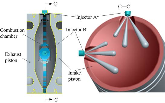
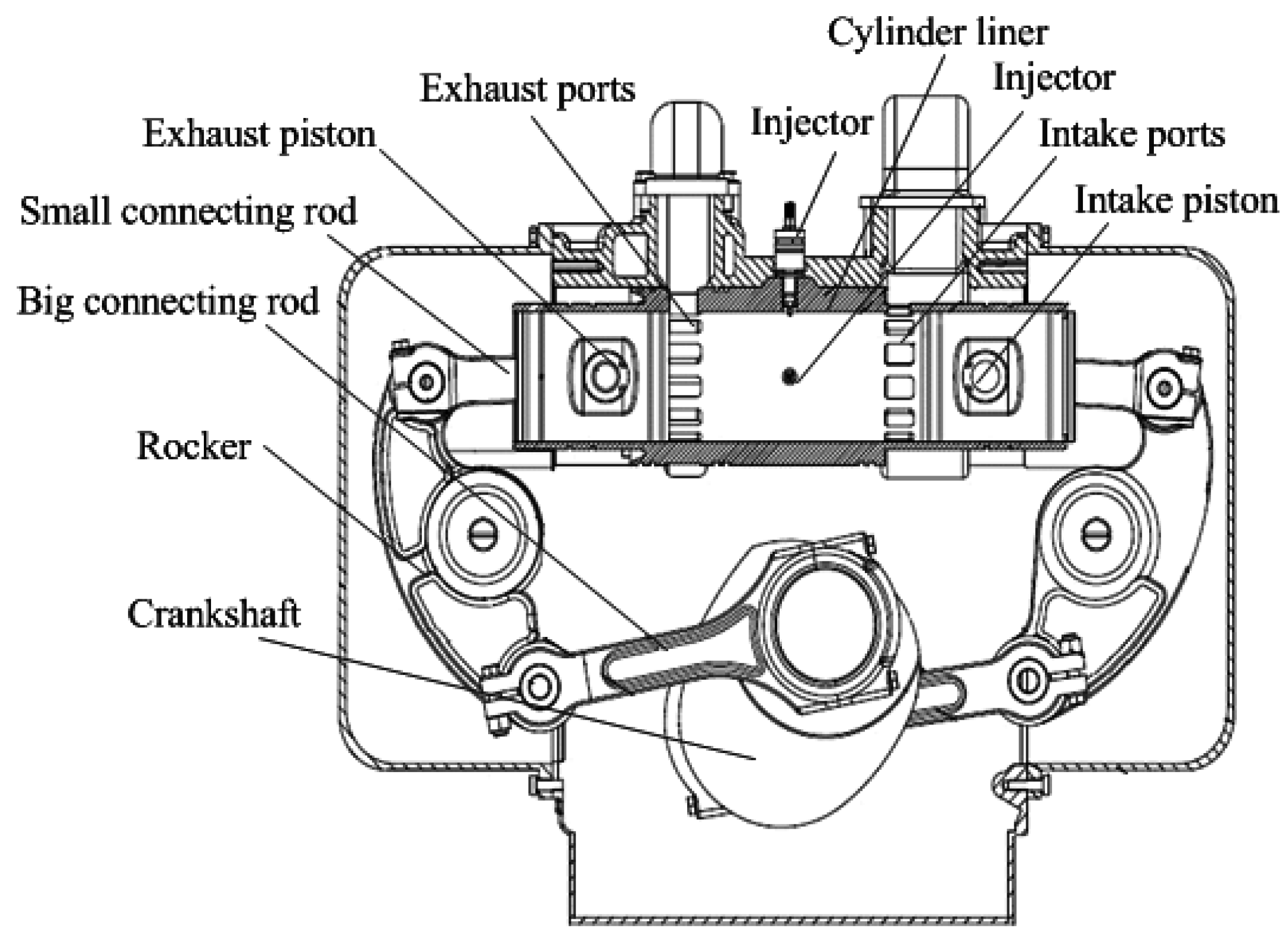
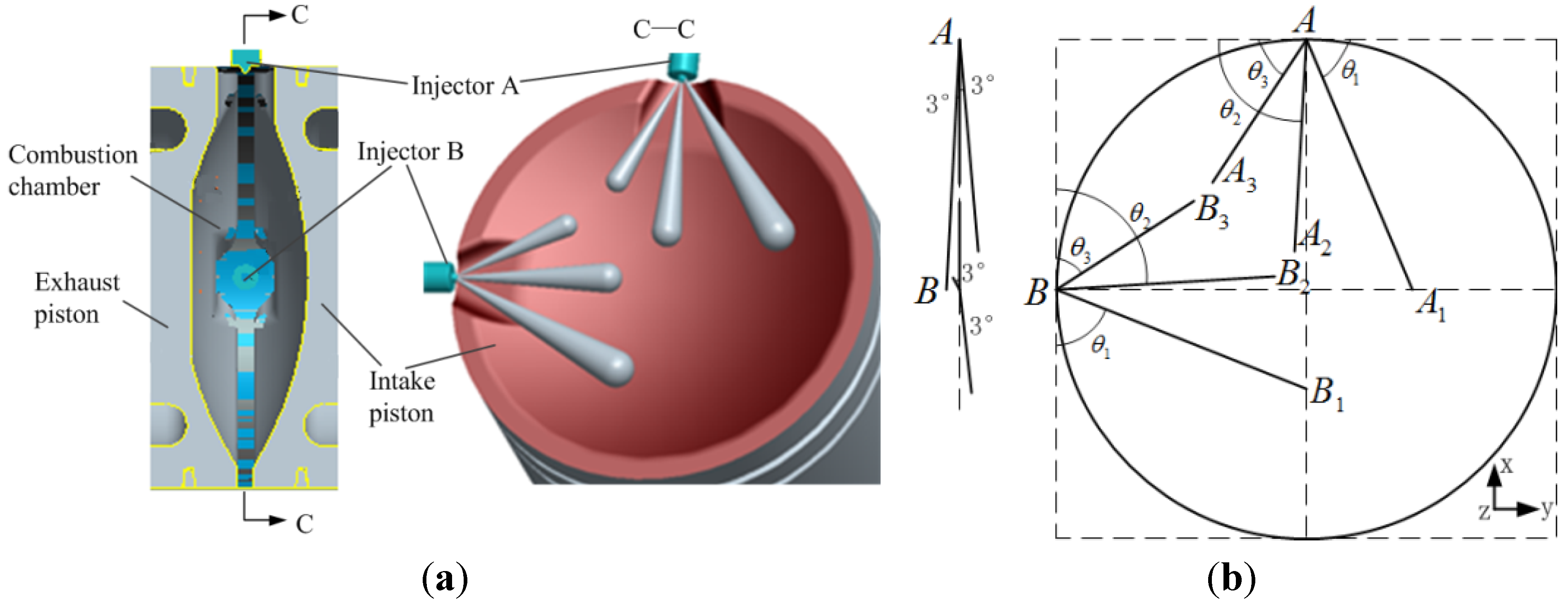
2.1. OPFC Diesel Engine Concept

As shown in Figure 1, the cylinder of an OPFC diesel engine is horizontal and the injector was placed on the cylinder liner. Meanwhile, at the end of the liner there are gas ports, intake ports on one side and exhaust ports on the other side. Intake ports are used for in-cylinder fresh air delivery, and exhaust ports were used to remove burnt gases from the cylinder. Two pistons are placed in the same cylinder liner, a combustion chamber is formed when two pistons move to the most closed position as shown in Figure 2, which is inner dead center (IDC). Rockers are placed on either ends of the cylinder body; the upper end of the rocker is connected to the piston by a small connecting rod, and the lower end of the rocker is connected to the crankshaft by a big connecting rod. The reciprocating movements of the pistons are driven by crankshaft through the rockers and connecting rods. The pistons can be defined by the different positions of the control gas ports. The piston that controls the opening and closing of intake ports is defined as the intake piston and the piston that controls the opening and closing of the exhaust ports is defined as the exhaust piston. Usually a phase difference between intake piston and exhaust piston is an effective way to improve gas exchange performance in an OPFC engine by changing scavenging duration and timing. At the same time, due to the opposed-piston motion phase difference, opposed-pistons on both sides cannot arrive at each top dead center (TDC) simultaneously. When opposed-pistons are around IDC, the opposed-pistons’ relative velocity affects the isochoric combustion duration. When the opposed-pistons are approaching IDC, the greater the motion phase difference is, the smaller the relative velocity is. This is caused by the opposed-piston motion phase difference, which results in the phenomenon that when the exhaust piston is moving away from the IDC, the intake piston will be close to the IDC. There is a catch-up process between two pistons, and the bigger the phase difference is, the longer the catch-up process will be [18,19]. The engine specifications are listed in Table 1.
Figure 1. OPFC diesel engine concept.
Energies 08 06365 g001
Table 1. OPFC diesel engine specifications.
Specification ItemValue
Number of the culinder(-)2
Bore (mm)100
Stroke (intake/exhaust) (mm)110/110
Nominal compression ratio (-)22
Trapping compression ratio (-)15.8
Displacement (L)3.4
Opposed-piston motion phase difference (°CA)17
Exhaust valve open (AIDC) (°CA)100
Intake valve open (AIDC) (°CA)116
Exhaust valve close (BIDC) (°CA)113
Intake valve close (BIDC) (°CA)110
Maximum engine power (kW)80 @ 2400 rpm
Maximum engine moment (N.m)420 @ 1600 rpm
Figure 2 shows OPFC diesel engine combustion chamber and injector position. Thinking about scavenging flow, the intake and exhaust pistons are distinguished from each other in their design. The intake piston is round and the exhaust piston has a shallow pit on the surface. Two injectors are placed on the cylinder liner at a 90 degree angle from each other.
Figure 2. (a) OPFC diesel engine combustion chamber and injector position; (b) injector spraying direction.
Energies 08 06365 g002

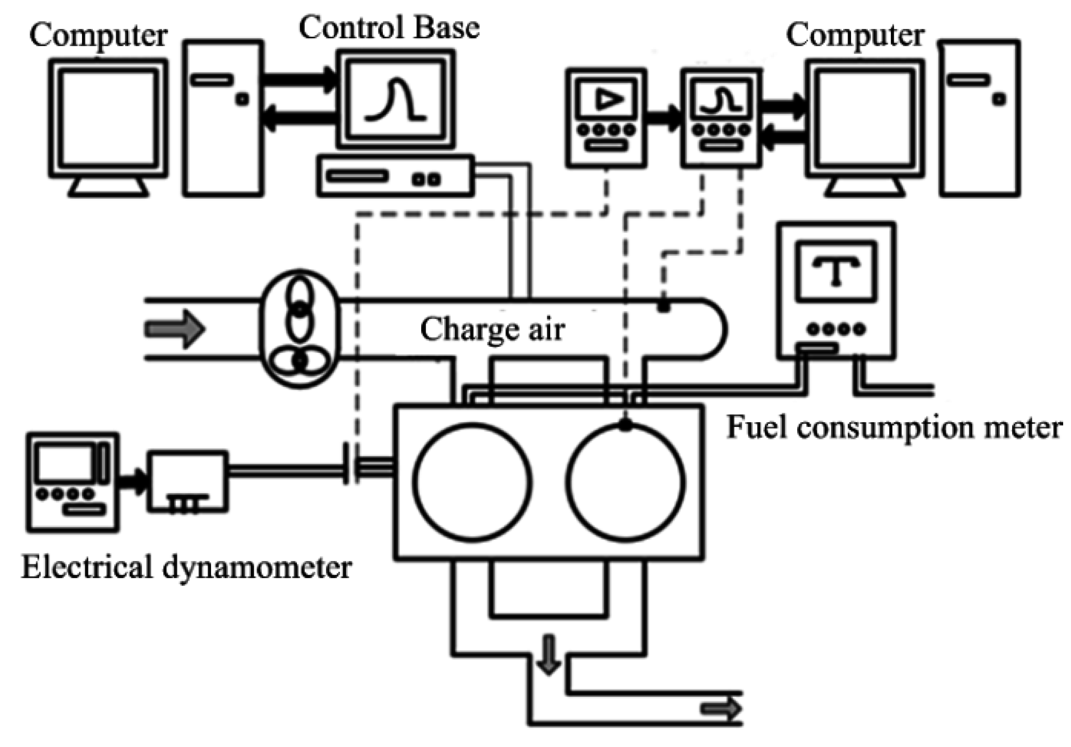
2.2. Experimental Set-up

The experiment is performed in an OPFC diesel engine prototype developed by the Beijing Institute of Technology. The schematic of the engine test bench is shown in Figure 3. The control system uses Control-Base, a fast prototyping tool, as a supporting platform. It can control fuel consumption and use Matlab/Simulink for programming, thus achieving accurate control over injection timing, fuel injection quantity, common rail pressure and other parameters under various OPFC diesel engine operating conditions.
Figure 3. Opposed-piston folded-cranktrain (OPFC) diesel engine experimental set-up.
Energies 08 06365 g003
In this experiment, the OPFC diesel engine is coupled with an electrical dynamometer to provide an engine load cell. A water-cooled cylinder pressure transducer (model 6056 A, Kistler Instrumente AG, Winterthur, Switzerland) was mounted on the first cylinder line to measure the CGP. The CGP data of 50 engine cycles were collected with a resolution of 0.25 °CA. Crankshaft position was obtained using a CA sensor to determine CGP as a function of CA. The crankshaft position signal is measured by a Kistler 2614B unit and its sampling precision is 0.2 °CA. Fuel consumption was determined by weighing the fuel used for a period of time on an electronic scale. Six different digital thermocouples monitored the temperatures of the intake air, fuel, engine oil, exhaust gas, coolant inlet and outlet.
Combustion characteristics of OPFC diesel engines under different loads were determined at a constant engine speed mode (1600 rpm, ±25 rpm). All tests were completed without any modifications to the test engine. The tests were carried out under steady-state conditions. The engine speed of 1600 rpm is the maximum engine torque region determined by the engine manufacturer at full load; this is the reason for engine speed selection in this study. For each test, the engine should be warmed up sufficiently, which ensures the initial conditions of the test: intake gas pressure and temperature is 1.2 bar and 310 ±3 K respectively, cooling water temperature is 350 ±3 K and the oil pressure is 5 bar. In each experiment run, measurements were repeated for three times, and the average data are used for in-cylinder working process analysis.

2.3. Calculation of Heat Release (HR)

HR calculations are an approach to acquire information about combustion processes. HR analysis is performed based on CGP data. A number of approaches to HR analysis have been presented in the literature. The most widely used one was developed by Krieger and Borman [20].
In this model, the experimental CGP data are used to compute an apparent fuel-burning rate. The model takes thermodynamic equilibrium as an assumption during in-cylinder combustion, but ignores temperature gradients, pressure waves, nonequilibrium conditions, fuel vaporization, mixing, etc. From the first law of thermodynamics:
d U d t = Q ˙ W ˙
m C v d T d t = Q ˙ P d V d t
where Q ˙ is the combination of the heat release rate and heat transfer rate across the cylinder wall, W ˙ is the rate of work done by the system due to system boundary displacement.
To simplify Equation (2) the ideal gas assumption can be used:
P V = m R T
Assuming constant mass, Equation (3) is differentiated as:
d T d t = 1 m R [ P d V d t + V d P d t ]
After combining these two equations, the heat release equation becomes:
Q ˙ = [ C v R + 1 ] P d V d t + C v R V d P d t
After replacing time (t) with the crank angle (θ); Equation (5) becomes:
Q ˙ = λ λ 1 P d V d θ + λ λ 1 V d P d θ
where λ is the ratio of specific heats; C p / C v which was taken as 1.35 for diesel heat release analysis; θ is crank angle; P is cylinder gas pressure; and V is cylinder volume [21].

3. Results and Discussion

3.1. Combustion Characteristics

3.1.1. Cylinder Gas Pressure (CGP)

Figure 4a illustrates the comparison of logarithmic P-V curve changes at various loads and 1600 rpm, which can be related to the differences in HR patterns. The peak CGP mainly depends on combustion rate in the initial stages, which is influenced by the fuel participating in the uncontrolled HR phase. In-cylinder gas endothermic processes can be divided into constant-volume and constant-pressure processes. In addition, the constant-volume process can be considered a premixed combustion process while the constant-pressure process can be considered a diffusion combustion process [15]. Figure 4a shows that since load changes have only slight effects on the premixed combustion phase, the cylinder pressure change is very small in the isochoric process. Because of the catch-up process between opposed-pistons around IDC, the relative velocity of opposed-pistons is smaller, which is beneficial to the isochoric combustion. In contrast, cylinder pressure changes substantially in the isobaric process. Pressure in the expansion process increases and the isobaric combustion process obviously shows an increase of IMEP because the heat transfer loss is less due to the opposed-piston combustion chamber geometry. OPFC diesel engine premixed combustion is similar to isochoric combustion. Its compression slopes and expansion processes curves are close to quantitative and each of the curves approximately matches adiabatic compression and expansion.
Figure 4. (a) CGP P-V logarithmic curves; (b) peak CGP values and points.
Energies 08 06365 g004
Figure 4b shows the effects on peak CGP values and points of various loads. In a compression ignition (CI) engine, the peak CGP value depends on combustion rate in premixed combustion phase. Due to the small increase in the premixed CD, increase of peak CGP value is not obvious. It can be seen that when the IMEP is 0.305 MPa, the peak CGP value is 6.6 MPa, and when the IMEP grows from 0.305 MPa to 0.703 MPa, the peak CGP value only increases by 5%. Therefore, load changes have little effect on peak CGP values. The peak CGP points were observed in terms of CA after IDC for different loads. Peak CGP point is significantly retarded with load growth. When IMEP is 0.703 MPa higher than its initial value of 0.305 MPa, the peak CGP point is consequently retarded by 3.4 °CA. Due to the smaller effect of load growth on the premixed combustion period, an increase of peak CGP value is not apparent. On the contrary, HR in diffusion combustion is greatly increased. Therefore, peak CGP value is increased by increasing load and its point is consequently delayed.

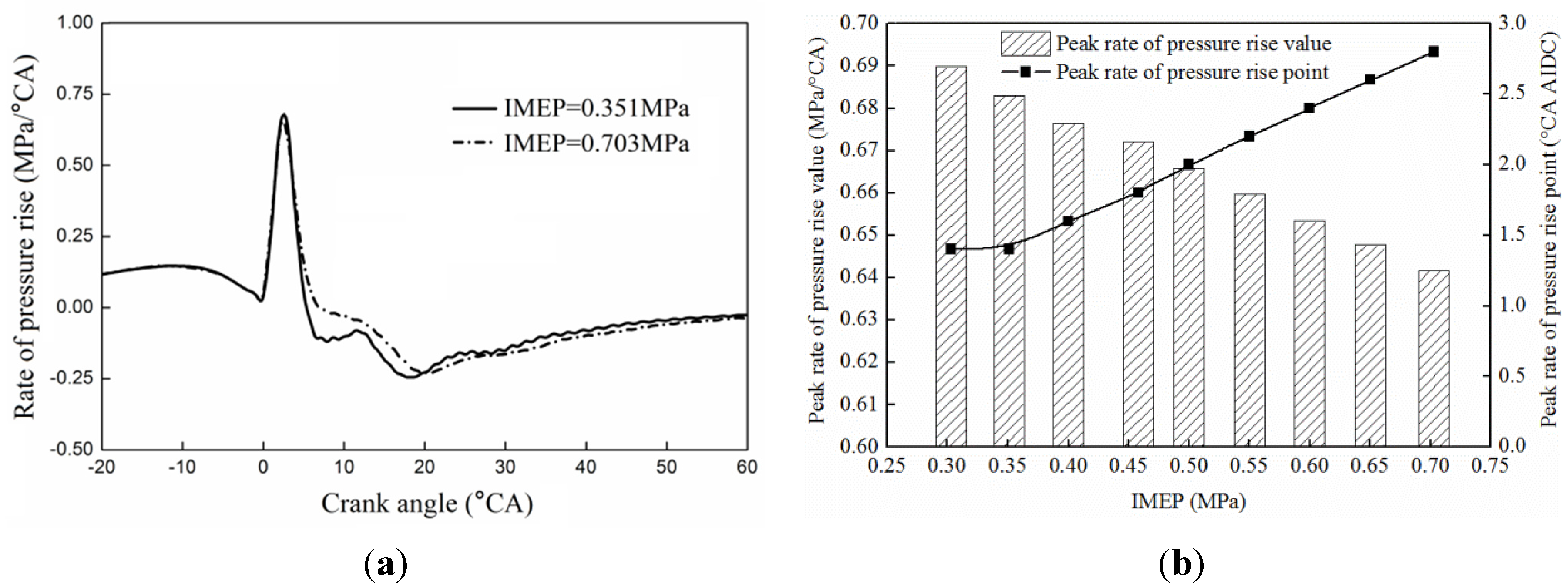
3.1.2. Rate of Pressure Rise (ROPR)

ROPR reflects combustion roughness, and it is an important parameter in the whole engine operation. Higher ROPR means a greater proportion of injected fuel is burnt in the premixed combustion phase [22]. Figure 5a compares the ROPR curves at 0.351 MPa and 0.703 MPa IMEP at 1600 rpm. The peak ROPR of 0.351 MPa IMEP approximates 0.66 MPa/°CA while at 0.703 MPa IMEP it is 0.655 MPa/°CA, which are all higher than conventional diesel engines. As a result, in-cylinder ROPR curves come closest in shape. The peak ROPR value and peak ROPR point in terms of CA after IDC at different loads are shown in Figure 5b. The increase in peak ROPR value as load grows is substantial. Moreover, peak ROPR point is also retarded for different IMEP values. This finding is best exemplified by the fact that the peak ROPR point is retarded by 1.6 °CA in this test.
Figure 5. (a) ROPR versus CA for different loads; (b) peak ROPR values and points.
Energies 08 06365 g005

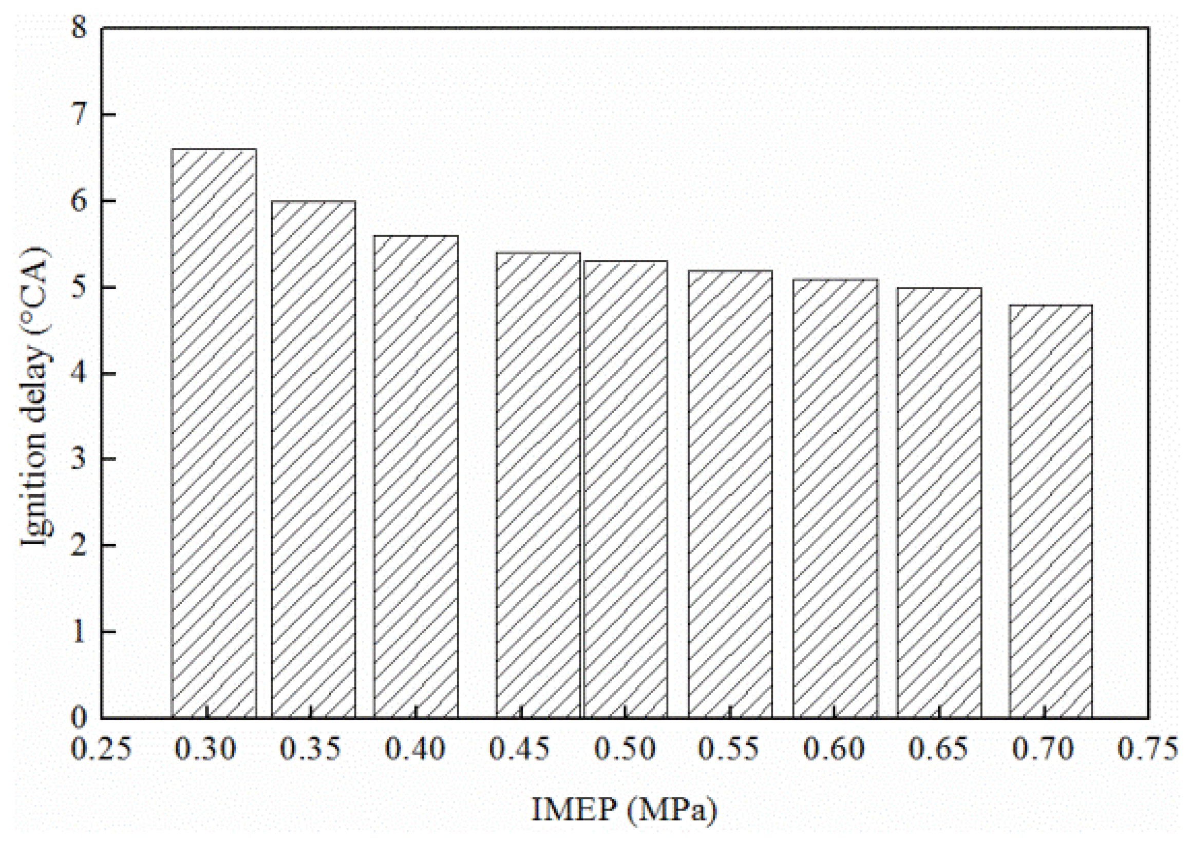
3.1.3. Ignition Delay (ID)

ID is an important parameter for combustion phenomenon description. Parameters such as fuel type, fuel quality, air-fuel ratio, engine speed, intake air temperature and pressure all influence the ID [23]. Different fuel quantities will be injected per stroke for the same crank angle volume at different loads. Figure 6 shows the ID at various loads when the engine speed is adjusted to 1600 rpm. Like the conventional diesel engine, ID was decreased with increasing load. ID was shortened by 0.6 °CA when the IMEP increases from 0.303 MPa to 0.351 MPa. However, this trend is gradually weakened as IMEP increases. When IMEP increases from 0.65 MPa to 0.703 MPa, ID drops by merely 0.2 °CA. Thus it can be concluded that ID remains unaffected by load changes.
Figure 6. ID at different loads.
Energies 08 06365 g006

3.2. Analysis of Heat Release

HR calculations attempt to learn more about the combustion process in an engine. Several important parameters such as rate of heat release (ROHR), cumulative heat release (CHR), center of heat release (COHR), and CD were determined by HR analysis.

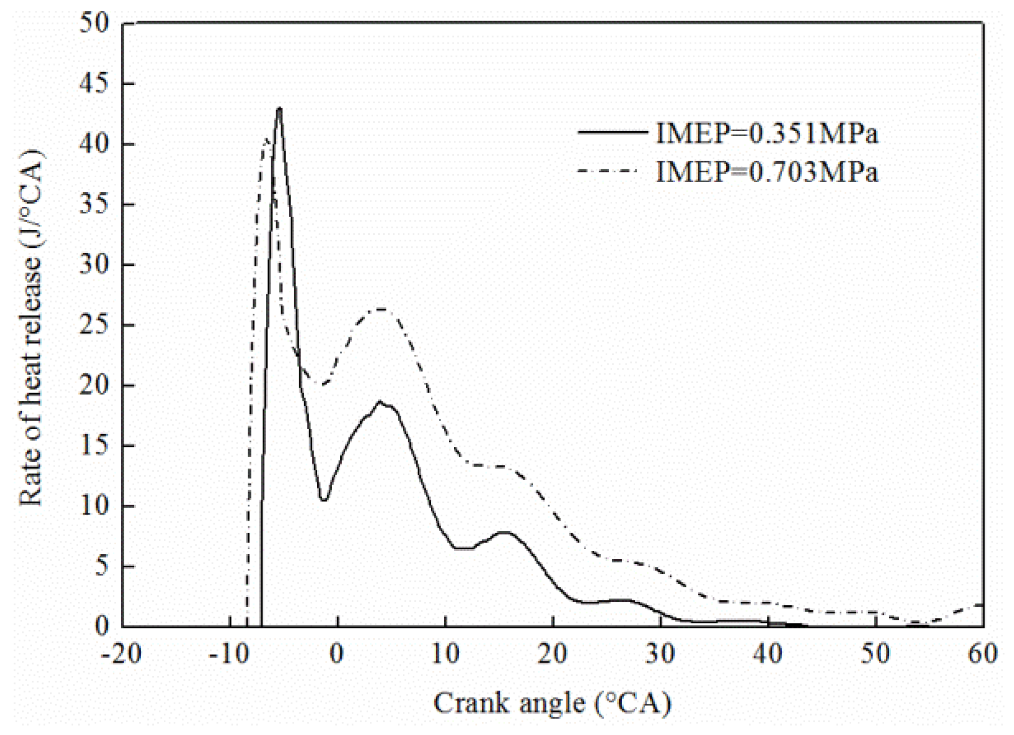
3.2.1. Rate of Heat Release (ROHR)

In Figure 7, a comparison is made between instantaneous ROHR at 0.351 MPa and 0.703 MPa IMEP at 1600 rpm. It shows that the HR curve of an OPFC diesel engine displays a significant “double hump”, just like conventional diesel engines.
Figure 7. ROHR versus CA for different loads.
Energies 08 06365 g007
Consequently, the OPFC diesel engine combustion process can be divided into ignition delay, premixed combustion, diffusion combustion and after combustion. When IMEP is 0.351 MPa, the peak ROHR value of the premixed combustion phase is around 43 J/°CA; while it dropped by 5.8% to approximately 40.5 J/°CA at 0.703 MPa IMEP. Peak ROHR value of the diffusion combustion phase is approximately 18.5 J/°CA at 0.351 MPa IMEP while it is increased by 43.3% at 0.703 MPa IMEP.

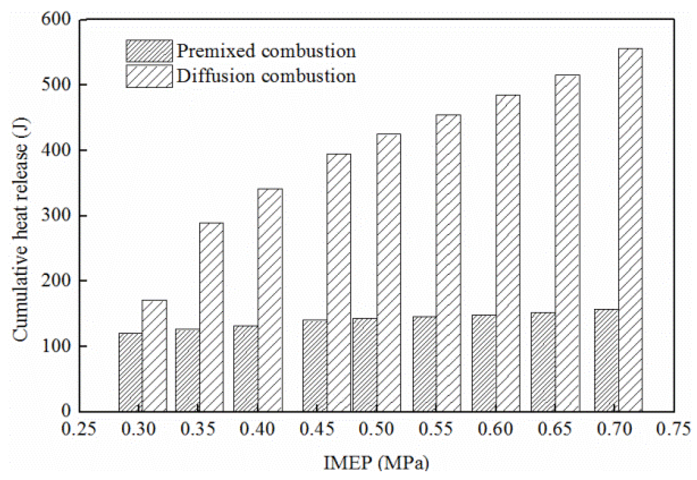
3.2.2. Cumulative Heat Release (CHR)

Figure 8 illustrates the CHR in premixed CD and diffusion CD at various loads at 1600 rpm. Despite the load increase, the OPFC diesel engine HR remains almost unchanged in premixed combustion, making the pressure around IDC vary by little. In comparison, based on a considerable HR growth in diffusion combustion, in-cylinder pressure is positively correlated to load increase in the expansion process. The result shows that load changes have more influence on diffusion combustion HR than on premixed combustion. It shows a rising tendency on the whole in these two stages as IMEP increases. When IMEP rises from 0.305 MPa to 0.703 MPa; HR in premixed CD increases by 30%. Particularly, this value for diffusion CD is 227%. On the other hand, the distinction in CHR also proves that the effect of CHR in diffusion combustion is significant, while almost does nothing to the HR in premixed combustion.
Figure 8. CHR at different loads.
Energies 08 06365 g008

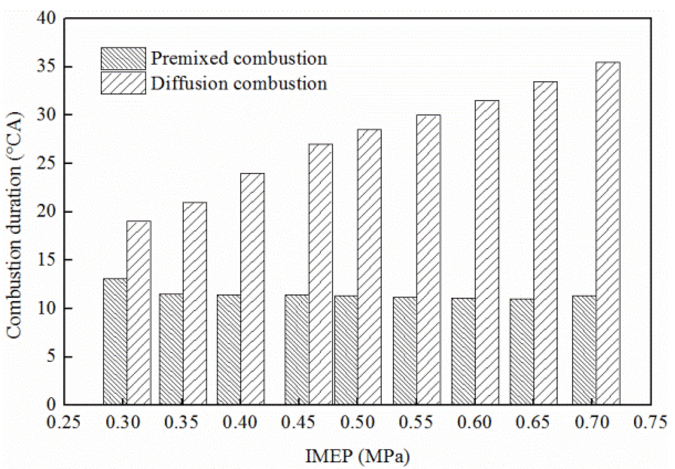
3.2.3. Combustion Duration (CD)

CD was calculated as the HR interval from the maximum ROPR to the maximum CHR. On the ROHR curve, the sudden rise in HR is considered as the start of combustion and the valley point between two peaks is the end of the premixed CD. The end of diffusion CD can be defined as the time when 90% of the fuel was burnt. Figure 9 shows premixed and diffusion CD at different loads when the engine speed is 1600 rpm. Premixed CD at all loads is shorter than diffusion CD, which shows a slightly declining tendency as load is increasing. When IMEP raises from 0.305 MPa to 0.703 MPa, premixed CD is thus lowered by 13%. By contrast, diffusion CD shows an opposite tend as it increases substantially with IMEP. When the IMEP raises from 0.305 MPa to 0.703 MPa, diffusion CD is increased by 87%. Overall, CD increases as IMEP rises. Thus, effect on diffusion CD of load changes is more significant than that on premixed CD.
Figure 9. CD at different loads.
Energies 08 06365 g009

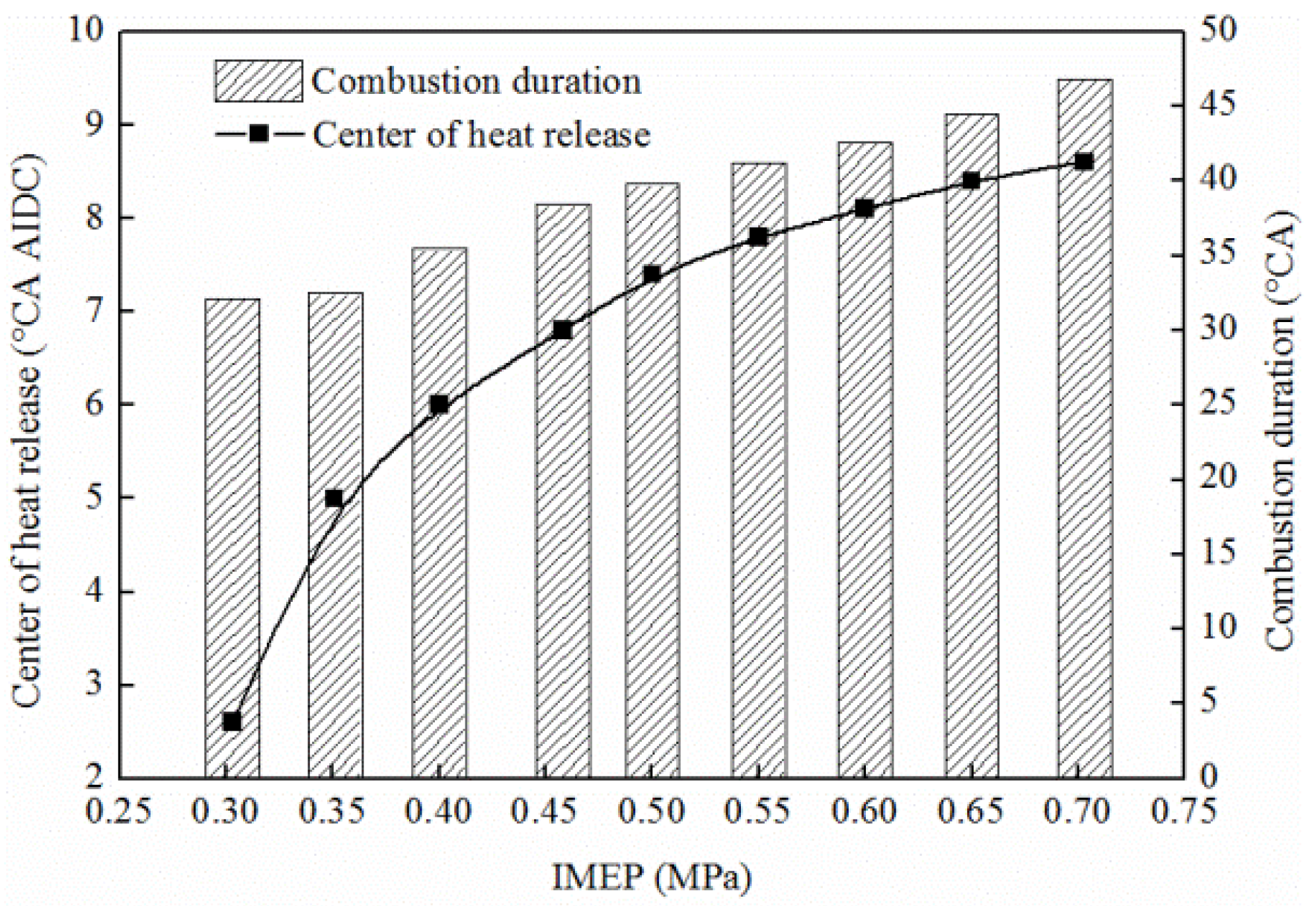
3.2.4. Center of Heat Release (COHR)

COHR is very important for an internal combustion engine. It is defined as the time when 50% of the fuel was burnt. COHR is calculated as CA by using the expression given below:
θ c = θ s θ e d Q d θ θ d θ θ s θ e d Q d θ d θ
where θ c is the center angle of combustion; θ s is the starting angle of combustion; θ e is the ending angle of combustion; θ is the crank angle; Q is the heat release. Figure 10 illustrates COHR at different loads at 1600 rpm.
Figure 10. COHR and CD at different loads.
Energies 08 06365 g010
As CD increases with the rising IMEP, COHR appears to go away from IDC, yet such a phenomenon becomes less prominent with load increase. Compared with conventional diesel, the COHR can close to the IDC at the high engine load and the indicated thermal efficiency is improved. Similarly, the CD is positively correlated to the increasing load. When IMEP increases from 0.305 MPa to 0.703 MPa, COHR is then retarded by 6 °CA. Meanwhile, CD is also extended by 14.7 °CA, 45.7% higher than the previous one.

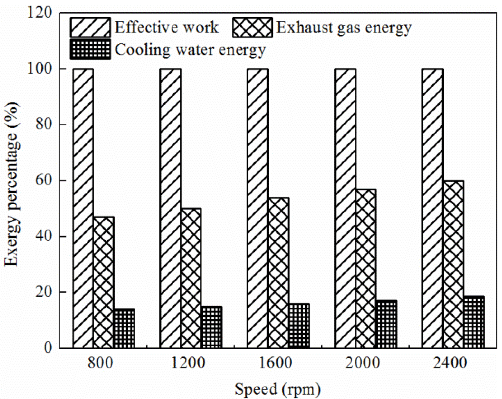
3.3. Analysis of Waste Heat Energy

The OPFC diesel engine features two-stroke operation and uniflow scavenging, which may result in high exhaust pressures and temperatures. Thus, it has relatively high-quality waste heat energy. According to the second law of thermodynamics [24], the evaluation indicator of energy is not only the quantity, but also the quality. Compared to effective mechanical energy, waste heat energy is a kind of low-grade energy since it requires various kinds of thermodynamic cycles to convert it into effective work. In accordance with the Carnot principle, the maximum efficiency of thermodynamic cycles cannot be higher than Carnot cycle efficiency. Thus, only part of waste heat energy can be recovered. From this viewpoint, exergy analysis is more useful to evaluate the waste heat energy characteristics [25,26].
Waste heat energy will be studied by using the exergy analysis method for the sake of revealing its recovery potential. Exergy is also called available energy used for energy quality evaluation. It indicates the maximum recoverable energy of waste heat energy [27]. The mathematical expression of exergy is given as:
E X , Q = Q ( 1 T 0 T )
where EX,Q is the exergy of waste heat energy; Q is quantity of waste heat energy; T0 is ambient temperature and T is waste heat temperature.
In order to better evaluate the quality of waste heat energy, exergy percentage is defined, and its calculation formula is written as:
η E x e , p = E X , Q Q 100 % = ( 1 T 0 T ) 100 %
where η E x e , p represents the exergy percentage of each kind of waste heat energy. As can be seen from Equation (9), exergy percentage is just a temperature monodrome function. After the ambient temperature is fixed, the exergy percentage increases with waste heat energy temperature.
Figure 11 shows the exergy percentages of effective work, exhaust gas energy and cooling water energy under full load. As can be seen from the Figure 11, the exergy percentage of exhaust gas energy is higher than 50% except at the speed of 800 rpm. That is, theoretically, about 50% of exhaust gas energy can be recovered under full load. However, the exergy percentage of cooling water energy is always lower than 20%. It means that the percentage of recoverable cooling water energy is less than 20%. The cooling water exergy percentage is much lower than exhaust gas exergy percentage, so the recovery potential of cooling water energy is also much lower than that of exhaust gas energy. Furthermore, Figure 11 shows the grades of various kinds of energy in an OPFC diesel engine. As the effective work is mechanical energy, its exergy percentage is 100%. Consequently, in OPFC diesel engine from effective work, exhaust gas energy to cooling water energy, the energy grades reduce in turn.
Figure 11. Exergy percentages of different energies under full load.
Energies 08 06365 g011
In order to better evaluate the recovery potential of exhaust gas energy in an OPFC diesel engine, the concept of exergy efficiency (available energy efficiency) is proposed [27]. Exergy efficiency is defined as the percentage of exergy in the total fuel energy. Equation (10) is used to quantify the exhaust gas exergy efficiency, which is dividing the exergy content of exhaust gases by the amount of energy you have available (engine total fuel energy):
η E x e , e f f e x h = E X , Q e x h H f u e l 100 %
where η E x e , e f f e x h is the exhaust gas exergy efficiency, E X , Q e x h is the exergy of exhaust gas heat energy, H f u e l is the fuel chemical energy.
According to Equation (8), the exergy of exhaust gas heat energy is given as:
E X , Q e x h = Q e x h ( 1 T 0 T e x h )
where E X , Q e x h is the exergy of exhaust gas heat energy; Q e x h is quantity of exhaust gas heat energy; T 0 is ambient temperature and T e x h is the exhaust gas temperature.
Figure 12 shows the exhaust gas exergy efficiency of OPFC diesel engine at different loads. As shown in this figure, exhaust gas exergy efficiency is not sensitive to the speed. The higher the load is, the higher the exhaust gas exergy efficiency will be. The highest exhaust gas exergy efficiency is larger than 25% under high-speed and high-load operating conditions. It means that fuel efficiency of this engine can be improved by 25% at most by exhaust gas energy recovery.
Figure 12. Exhaust gas exergy efficiency.
Energies 08 06365 g012

4. Conclusions

Based on experimental results and working process analysis using the first and second laws of thermodynamics, the following conclusions can be drawn:
(1)
The heat release process of OPFC diesel engines can be divided into four phases: ignition delay, premixed combustion, diffusion combustion and after combustion, which have more significant isochoric and isobaric combustion because of a smaller relative velocity of opposed-pistons and heat transfer loss around IDC.
(2)
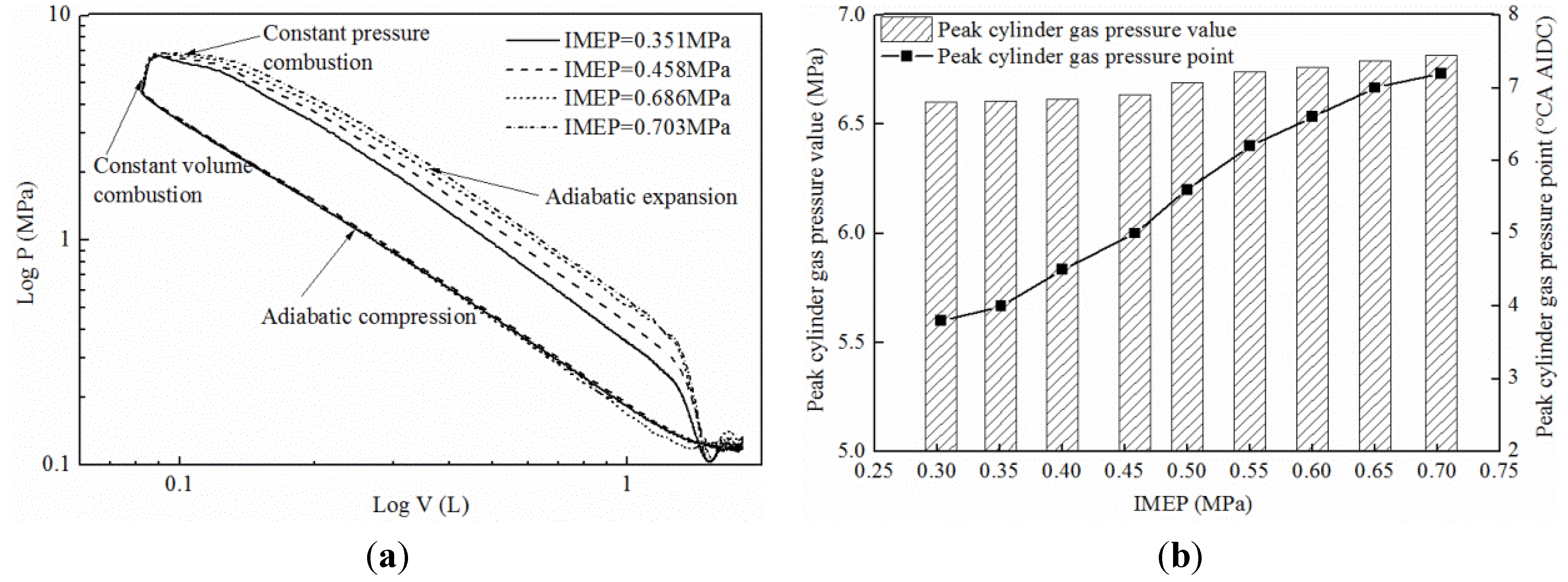
With an increasing IMEP, premixed CD increases slightly while diffusion CD increases significantly, resulting in a slight increase of CGP in premixed CD while it increases substantially in diffusion CD. When IMEP increases from 0.351 MPa to 0.703 MPa, peak ROPR is shortened by 7%.
(3)
The relative movement rule of opposed-pistons is a main impact factor for the combustion process of OPFC diesel engines. A smaller relative velocity of the opposed-pistons around IDC results in more obvious isochoric combustion so the ROPR is higher than in a conventional diesel engine. With the increase of IMEP, isobaric combustion is obvious because the heat transfer loss is less in the opposed-piston combustion chamber components.
(4)
An OPFC diesel engine features high exhaust pressure and temperature due to its two-stroke and uniflow scavenging characteristics, through which relatively high-quality exhaust gas heat energy is produced. The available energy efficiency is about 50% of exhaust gas energy and 25% of the total fuel energy can be recovered under full load.

Acknowledgments

The authors gratefully acknowledge the financial support by the Foundation Research Funds of the Ministry of Industry and Information Technology of the People’s Republic of China.

Author Contributions

Fukang Ma and Changlu Zhao designed the experimental set-up; Zhenfeng Zhao, Zhaoyi Xie and Fukang Ma performed the experiments; Zhenfeng Zhao, Zhenyu Zhang and Hao Wang analyzed the data; Fukang Ma and Fujun Zhang contributed to the editing and reviewing of the document.

Conflicts of Interest

The authors declare no conflict of interest.

Nomenclature

AIDCafter inner dead centerIDignition delay
BIDCbefore inner dead centerIDCinner dead center
CAcrank angleIMEPindicated mean effective pressure
CDcombustion durationOPOCopposed-piston and opposed-cylinder
CGPcylinder gas pressureOPFCopposed-piston folded-cranktrain
CHRcumulative heat releaseOP2Sopposed-piston two-stroke
CIcompression ignitionrpmrevolution per minute
COHRcenter of heat releaseROPRrate of pressure rise
HCCIhomogeneous charge compression ignitionROHRrate of heat release
HRheat releaseTDCtop dead center

References

  1. Callahan, B.J.; Wahl, M.H.; Froelund, K. Oil consumption measurements for a modern opposed-piston two-stroke diesel engine. In Proceedings of the ASME 2011 Internal Combustion Engine Division Fall Technical Conference, Morgantown, WV, USA, 2–5 October 2011; pp. 1019–1028.
  2. Kalebjian, C.; Redon, F.; Wahl, M. Low Emissions and Rapid Catalyst Light-off Capability for Upcoming Emissions Regulations with an Opposed-Piston, Two-Stroke Diesel Engine; Global Automotive Management Council and Emissions: Troy, MI, USA, 2012. [Google Scholar]
  3. Hofbauer, P. Opposed Piston Opposed Cylinder (OPOC) Engine for Military Ground Vehicles; SAE Technical Paper 2005-01-1548; SAE: Warrendale, PA, USA, 2005. [Google Scholar]
  4. Hirsch, N.R.; Schwarz, E.E.; McGough, M.G. Advanced Opposed-Piston Two-Stroke Diesel Demonstrator; SAE Technical Paper 2006-01-0926; SAE: Warrendale, PA, USA, 2006. [Google Scholar]
  5. Herold, R.E.; Wahl, M.H.; Regner, G.; Lemke, J.U.; Foster, D.E. Thermodynamic Benefits of Opposed-Piston Two-Stroke Engines; SAE Technical Paper 2011-01-2216; SAE: Warrendale, PA, USA, 2011. [Google Scholar]
  6. Pirault, J.P.; Flint, M. Opposed-Piston Engines: Evolution, Use, and Future Applications; SAE International: Warrendale, PA, USA, 2010. [Google Scholar]
  7. Naik, S.; Johnson, D.; Koszewnik, J.; Fromm, L.; Redon, F. Practical Applications of Opposed-Piston Engine Technology to Reduce Fuel Consumption and Emissions; SAE Technical Paper 2013-01-2754; SAE: Warrendale, PA, USA, 2013. [Google Scholar]
  8. Regner, G.; Herold, R.E.; Wahl, M.H.; Dion, E. The Achates Power Opposed-Piston Two-Stroke Engine: Performance and Emissions Results in a Medium-Duty Application; SAE Technical Paper 2011-01-2221; SAE: Warrendale, PA, USA, 2011. [Google Scholar]
  9. Redon, F.; Kalebjian, C.; Kessler, J.; Rakovec, N.; Headley, J. Meeting Stringent 2025 Emissions and Fuel Efficiency Regulations with an Opposed-Piston, Light-Duty Diesel Engine; SAE Technical Paper 2014-01-1187; SAE: Warrendale, PA, USA, 2014. [Google Scholar]
  10. Francisco, B.; Santos, A.; Gregorio, J. Computational analysis of the scavenging of a two-stroke opposed piston diesel engine. In Proceedings of the 2010 International Conference of Mechanical Engineering, London, UK, 30 June–2 July 2010; Volume 30.
  11. McGough, M.G.; Fanick, E.R. Experimental Investigation of the Scavenging Performance of a Two-Stroke Opposed-Piston Diesel Tank Engine; SAE Technical Paper 2001-01-1591; SAE: Warrendale, PA, USA, 2004. [Google Scholar]
  12. Xu, H.J.; Song, J.O.; Yao, C.D. Simulation on in-cylinder flow on mixture formation and combustion in OPOC engine. Trans. CSICE 2009, 27, 395–400. [Google Scholar]
  13. Xu, S.; Wang, Y.; Zhu, T. Numerical analysis of two-stroke free piston engine operating on HCCI combustion. Appl. Energy 2011, 88, 3712–3725. [Google Scholar] [CrossRef]
  14. Heywood, J.B. Internal Combustion Engines Fundamentals; McGraw Hill International: New York, NY, USA, 1988. [Google Scholar]
  15. Rakopoulos, C.D.; Giakoumis, E.G. Second-law analyses applied to internal combustion engines operation. Prog. Energy Combust. Sci. 2006, 32, 2–47. [Google Scholar] [CrossRef]
  16. Franke, M.; Huang, H.; Liu, J.P. Opposed Piston Opposed Cylinder (opoc™) 450 hp Engine: Performance Development by CAE Simulations and Testing; SAE Technical Paper 2006-01-0277; SAE: Warrendale, PA, USA, 2006. [Google Scholar]
  17. Zhao, Z.F.; Wu, D.; Zhang, F.J. Design and Performance Simulation of Opposed-Piston Folded-Cranktrain Engines; SAE Technical Paper 2014-01-1638; SAE: Warrendale, PA, USA, 2014. [Google Scholar]
  18. Xie, Z.Y.; Zhao, Z.F.; Zhang, Z.Y. Numerical Simulation of an Opposed-Piston Two-Stroke Diesel Engine; SAE Technical Paper 2015-01-0404; SAE: Warrendale, PA, USA, 2015. [Google Scholar]
  19. Ma, F.K.; Zhao, C.L.; Zhang, S.L. Scheme Design and Performance Simulation of Opposed-Piston Two-Stroke Gasoline Direct Injection Engine; SAE Technical Paper 2015-01-1276; SAE: Warrendale, PA, USA, 2015. [Google Scholar]
  20. Krieger, R.B.; Borman, G.L. The Computation of Applied Heat Release for Internal Combustion Engines; ASME Paper 66-WA/DGP-4; SAE: Warrendale, PA, USA, 1966. [Google Scholar]
  21. Brunt, M.F.J.; Rai, H.; Emtage, A.L. The Calculation of Heat Release Energy from Engine Cylinder Pressure Data; SAE Technical Paper 981052; SAE: Warrendale, PA, USA, 1998. [Google Scholar]
  22. Selim, M.Y.E.; Radwan, M.S.; Elfeky, S.M.S. Combustion of jojoba methyl ester in an indirect injection diesel engine. Renew Energy 2003, 28, 1401–1420. [Google Scholar] [CrossRef]
  23. Ozsezen, A.N.; Canakci, M.; Turkcan, A.; Sayin, C. Performance and combustion characteristics of a DI diesel engine fueled with waste palm oil and canola oil methyl esters. Fuel 2009, 88, 629–636. [Google Scholar] [CrossRef]
  24. Azoumah, Y.; Blin, J.; Daho, T. Exergy efficiency applied for the performance optimization of a direct injection compression ignition (CI) engine using biofuels. Renew Energy 2009, 34, 1494–1500. [Google Scholar] [CrossRef]
  25. Abusoglu, A.; Kanoglu, M. Exergetic and thermoeconomic analyses of diesel engine powered cogeneration. Part 1–Formulations. Appl. Therm. Eng. 2009, 29, 234–241. [Google Scholar] [CrossRef]
  26. Gungor, A.; Erbay, Z.; Hepbasli, A. Exergoeconomic analyses of a gas engine driven heat pump drier and food drying process. Appl. Energy 2011, 88, 2677–2684. [Google Scholar] [CrossRef]
  27. Fu, J.Q.; Liu, J.P.; Feng, R.H. Energy and exergy analysis on gasoline engine based on mapping characteristics experiment. Appl. Energy 2013, 102, 622–630. [Google Scholar] [CrossRef]

