Article

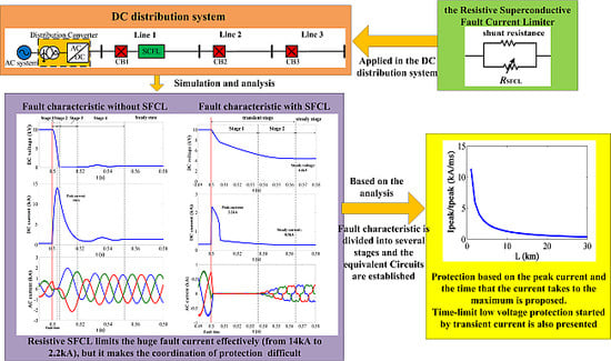
Protection Principle for a DC Distribution System with a Resistive Superconductive Fault Current Limiter

The Key Laboratory of Smart Grid of Ministry of Education, Tianjin University, Tianjin 300072, China
*
Author to whom correspondence should be addressed.
Energies 2015, 8(6), 4839-4852; https://doi.org/10.3390/en8064839
Submission received: 13 February 2015 / Accepted: 14 May 2015 / Published: 26 May 2015
(This article belongs to the Special Issue Electrical Power and Energy Systems for Transportation Applications)

Abstract

:
A DC distribution system, which is suitable for access to distributed power generation and DC loads, is one of the development directions in power systems. Furthermore, it could greatly improve the energy efficiency and reduce the loss of power transportation. The huge short circuit current is always a great threat to the safety of the components, especially the capacitors and diodes. A resistive superconductive fault current limiter (SFCL), which could respond quickly once a fault happens and limit the fault current to a relatively low level, becomes a good solution to this problem. In this paper, the operational principle of the resistive SFCL is introduced first, and then, the DC short-circuit fault characteristic of the DC distribution system with the SFCL is analyzed and the effectiveness of the SFCL verified. In order to realize the selectivity of the protection in the DC distribution system with SFCL, a new transient current protection principle based on Ip (the peak value of the current) and tp (the transient time that the current takes to reach its peak value) is proposed. Finally, a model of a 10-kV DC distribution system with an SFCL is established and simulated in PSCAD/METDC. Simulation results have demonstrated the validity of the analysis and protection principle.

Graphical Abstract

1. Introduction

Nowadays, more and more electric appliances, such as electric vehicles, LED lamps, mobile phones and computers, are becoming DC consumers with the development of power electronics technology. Scholars are now putting forward the DC distribution system based on the widely studied and applied distributed generation, which supplies DC power. Compared with the AC distribution system, a DC distribution system based on a voltage source converter (VSC) presents much more advantages, such as better power quality, larger power transportation capacity, higher reliability, being more economical, having lower energy waste, and so on [1,2,3,4,5]. Therefore, the research on DC the distribution system has drawn more and more attention.
However, in the DC distribution system based on a VSC, the Insulated Gate Bipolar Transistor (IGBTs) will be blocked from self-protection during the DC short-circuit fault. In this case, the VSC turns into an uncontrolled rectifier, as the freewheeling diodes will feed the fault [6]. In the meantime, the DC-link capacitance discharges, and the DC current rises rapidly to a relatively large value, which may be dozens of times the normal one and poses a considerable threat with respect to the safety issue. As a result, a current-limiting device is necessary, and the resistive superconductive fault current limiter (SFCL) is a good choice because of its fast response and low power loss characteristics [7].
Currently, SFCLs are mainly applied to the AC system. For example, a 220-kV saturated iron-core superconductive fault current limiter (SISFCL) has been installed in a high voltage transmission system in Tianjin, China. There are few studies about how resistive SFCL is to be used in the DC system, and some have evaluated its performance based on the effect of limiting the voltage and current only [8,9], while some studied the suitable location for the SFCL in the DC system considering the influence of the current only [7,9,10]. However, the influence of the SFCL on the fault characteristic and relay protection of the DC distribution system has had no research results till now. At present, most of the research about relay protection of the DC distribution system does not take the current limiters into consideration [11,12,13,14,15,16,17,18]. These protection schemes all apply a great short-circuit current and a low voltage. The impact of the SFCL on the protection of the DC distribution system needs to be further investigated, for introducing the SFCL will bring about problems with respect to protection.
In this paper, the fault characteristic of the DC distribution system with the SFCL and the influence of the SFCL on protection of the DC distribution system are studied. Then, a new transient current protection principle based on Ip (the peak value of the current) and tp (the transient time that the current takes to reach its peak value) is introduced and investigated in detail. Finally, many fault simulations are completed to verify the accuracy of the protection principle.

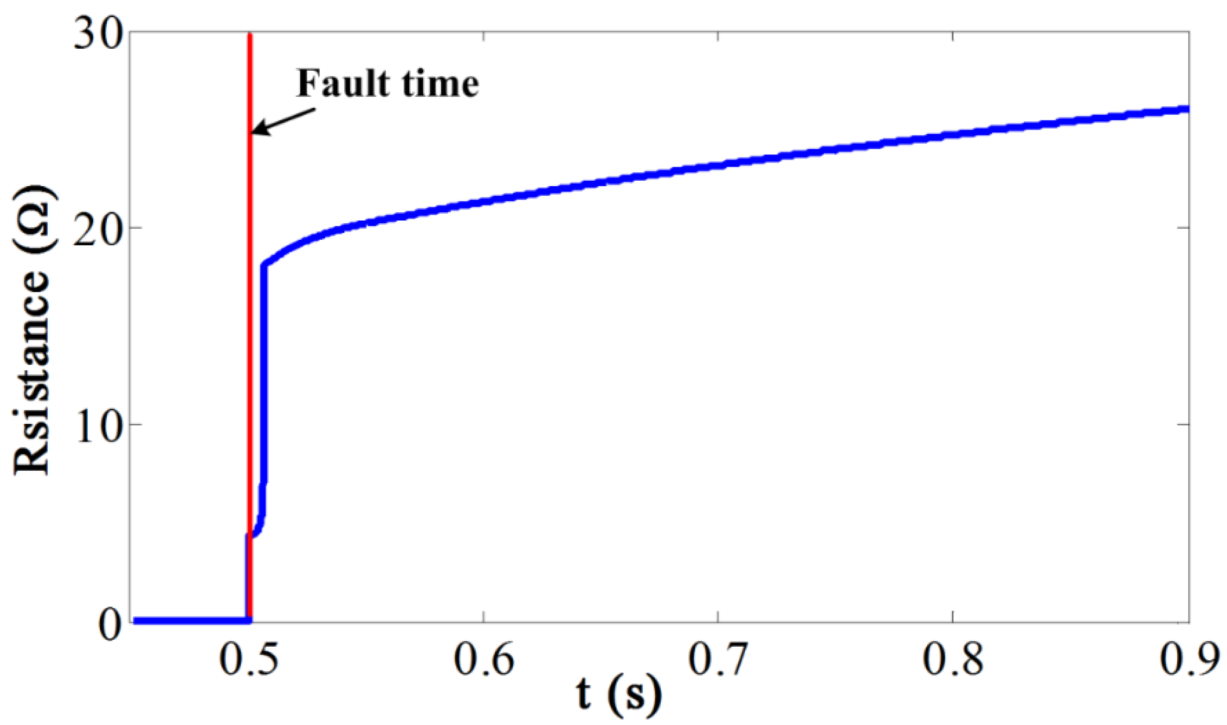
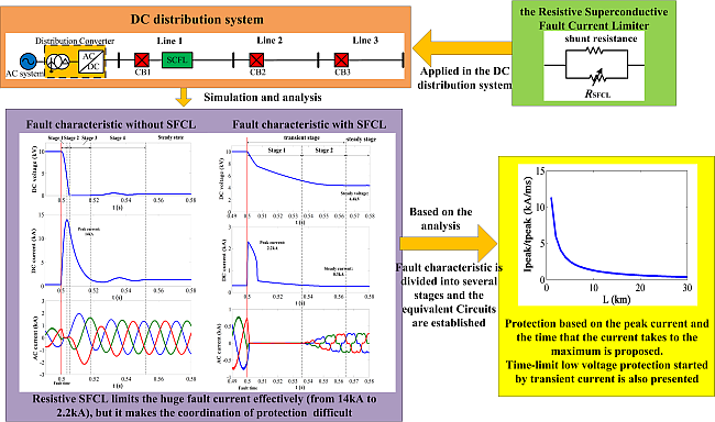
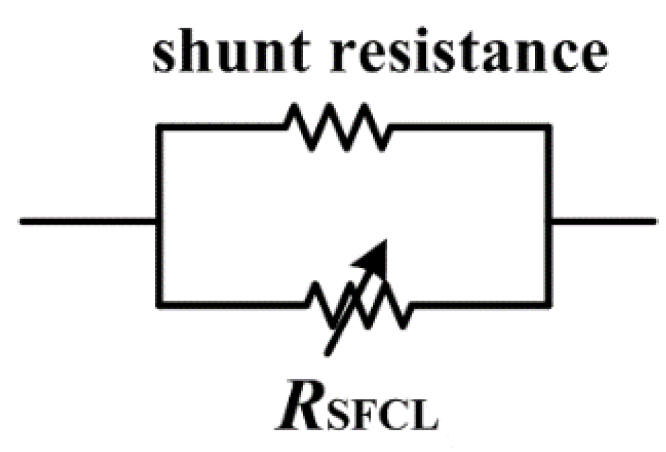
2. Resistive Superconducting Fault Current Limiter

A resistive SFCL is composed of a superconducting cable and a shunt resistance. The equivalent model of the SFCL is a variable resistance RSFCL and a shunt resistance in parallel, which is shown in Figure 1. The shunt resistance is necessary for reducing the overvoltage. Then, the resistive SFCL uses the transformation between the superconducting state and the normal resistive state to limit the increase of the current. When a fault happens, the resistive SFCL responds rapidly, so that the fault current is limited [8].
Figure 1. Structure of the resistive superconductive fault current limiter (SFCL).
Energies 08 04839 g001
In this paper, we choose Bi2212 as the material of the SFCL. The transformation of the resistive SFCL can be divided into three states as follows [8,19,20]:
(1) Superconducting state:
In this state, the current density going through the SFCL is below the critical value, and the resistance of the SFCL is very small. The electric field is:
E ( J , T ) = E c ( J J c ( T ) ) α
where Ec = 1 µV/cm; 5 ≤ α ≤ 15; J is the current density and Jc(T) is the critical current density, which is dependent on the temperature of the material. Additionally, the Jc(T) is:
J c ( T ) = J c ( 77 ) ( T c T T c T 0 )
where Tc is the critical temperature expressed in units of K; and T0 is the initial temperature. Here, Tc = 95 K; T0 = 77 K; and Jc(77) = 1.5 × 10⁷ A/m2.
(2) Flux flow state:
When the current density exceeds the critical value, the SFCL enters this state, and the electric field starts increasing. Then, the resistance of the SFCL begins increasing, and as a result, the current starts to be limited and the temperature of the material begins to increase. Additionally, the increase of temperature makes the Jc(T) decrease, so the electric field will increase continuously. In this state, the electric field is:
E ( J , T ) = E 0 ( E c E 0 ) β α J c ( 77 ) J c ( T ) ( J J c ( 77 ) ) β
where E0 = 0.1 V/m is the electric field during the transition from the superconducting state to the flux flow state. 2 ≤ β ≤ 4.
(3) Normal resistive state:
After the temperature gets higher than the critical temperature, the SFCL enters the normal resistive state. In this state, the resistance and the electric field are mainly dependent on the current density and the temperature. Additionally, the electric field is:
E ( J , T ) = ρ ( T c ) J T T c
where ρ(Tc) is the normal conducting resistivity, and here, ρ(Tc) = 1 × 10⁻⁶ Ω·m.
Overall, the resistance of the material is:
R sc = E i sc l sc
where the isc is the current going through the superconducting wire and lsc is the length of the wire.
Furthermore, in all three states, the heat diffusion equation is:
ρ v l sc S C d T d t = i sc 2 R sc T T 0 θ sc
where θsc = 1/[κ(lsc·2πr + 2S)]; κ = 1.5 × 10³ W/(K·m2); r is the radius of the superconducting wire and C = 1.58T (in units of J/(kg·K)). Here, the length of the superconducting wire is lsc = 200 m, and the volumetric density is ρv = 6 g/cm3. When the critical current is chosen, the cross-sectional area can be calculated by S = Ic/Jc.
The resistive SFCL model is established in PSCAD/EMTDC. In order to limit the surge current discharged by the capacitor, the resistance of the SFCL needs to become large enough quickly before the current gets to the peak value. In this paper, the length of the superconducting wire is assumed to be 200 m. In the DC distribution system, when a fault happens at 0.5 s, the variation of the resistance of the SFCL with respect to time is as shown in Figure 2.
Figure 2. Variation of the resistance of the SFCL.
Energies 08 04839 g002

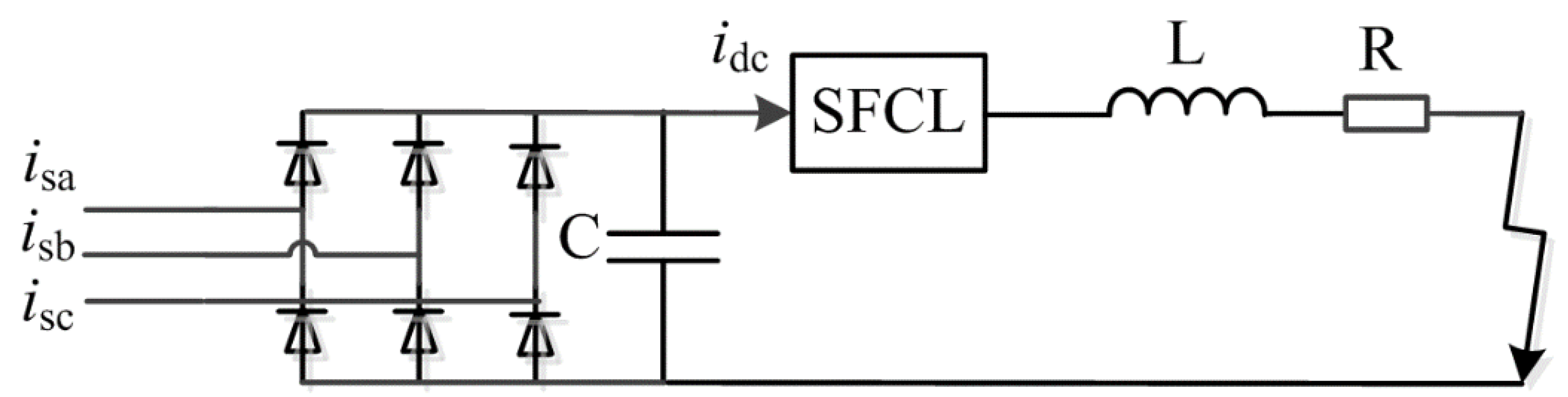
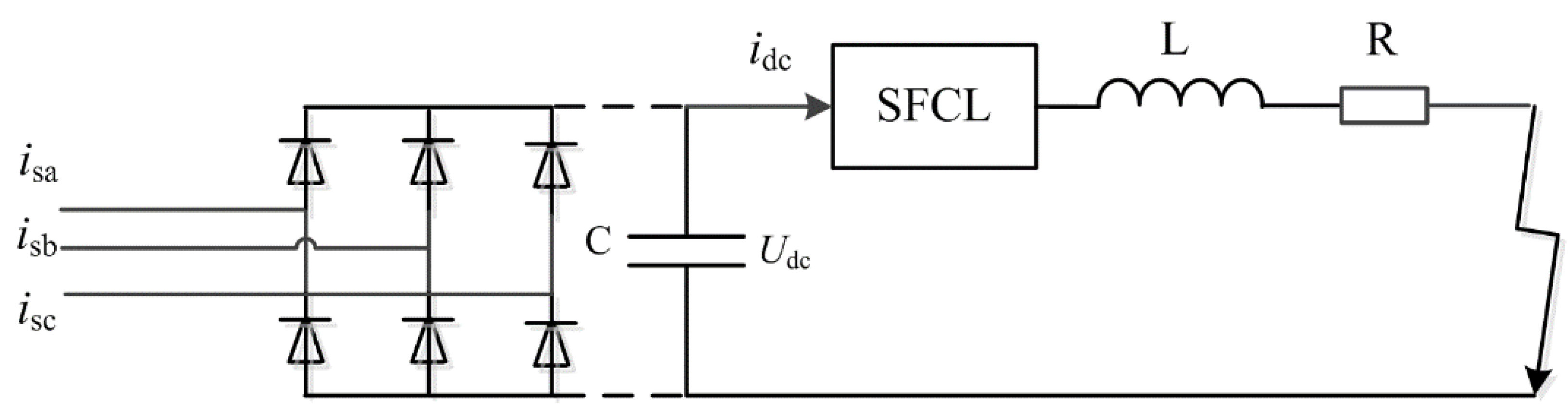
3. Analysis of Fault Characteristic in the DC Distribution System with the SFCL

When a DC short-circuit fault happens on the DC side of VSC, the IGBTs are blocked from self-protection. All of the diodes are blocked because of the reverse voltage. As a result, the AC system is separated from the DC side, and the AC current drops to zero [6]. If a SFCL is not used, the fault characteristic can be divided into four stages [16], which are shown in Figure 3. In the first stage, the capacitor discharges rapidly, and the DC current gets to a large value. This is a great threat to the safety of the capacitors. Additionally, in the third stage, the AC system is equivalent to a three-phase short circuit. These are unfavorable conditions for the system, and the large AC current is harmful for the diodes. Whether the third stage appears is decided by the damping property of the circuit. However, the installation of a resistive SFCL can limit the discharge of the capacitor and make the third stage disappear. Therefore, the resistive SFCL can limit the fault current on both the AC and DC sides, and the system will be safer. Then, the breaking capacity of the DC circuit breakers could be reduced. The fault characteristic under a particular situation of the simulation system is shown in Figure 4 and Figure 5.
Figure 3. The four stages for the rectifier during a DC short-circuit fault without the SFCL.
Energies 08 04839 g003
Figure 4. The fault characteristic of the voltage source converter (VSC) without the SFCL during a DC short-circuit fault.
Energies 08 04839 g004
Figure 5. The fault characteristic of the VSC with the SFCL during a DC short-circuit fault.
Energies 08 04839 g005
As shown in Figure 4 and Figure 5, the peak current is reduced from 14 down to 2.20 kA after the SFCL is installed, about an 84.3% decrease. The peak current is limited because of the fast operation of the SFCL. Furthermore, due to the SFCL, the time that the current takes from the beginning of the fault to the peak becomes shorter. In the steady state of the fault, the current is limited to a very low level with the increasing resistance of the SFCL. At this time, the current is close to 0.3 kA, even smaller than the normal value.
In addition, the decrease of the DC voltage is also limited by the SFCL. The rate of descent is reduced greatly. Additionally, the steady value of the voltage rises from about 1 up to 4.4 kV, about a 77% increase. Furthermore, once the SFCL is installed, the voltage will remain at a relatively high value, and the third stage disappears. Therefore, the resistive SFCL overcomes the equivalent three-phase short circuit on the AC side. For different distances of faults, the voltage of the steady state changes little.
The analysis of the fault characteristic is carried on in detail as follows.

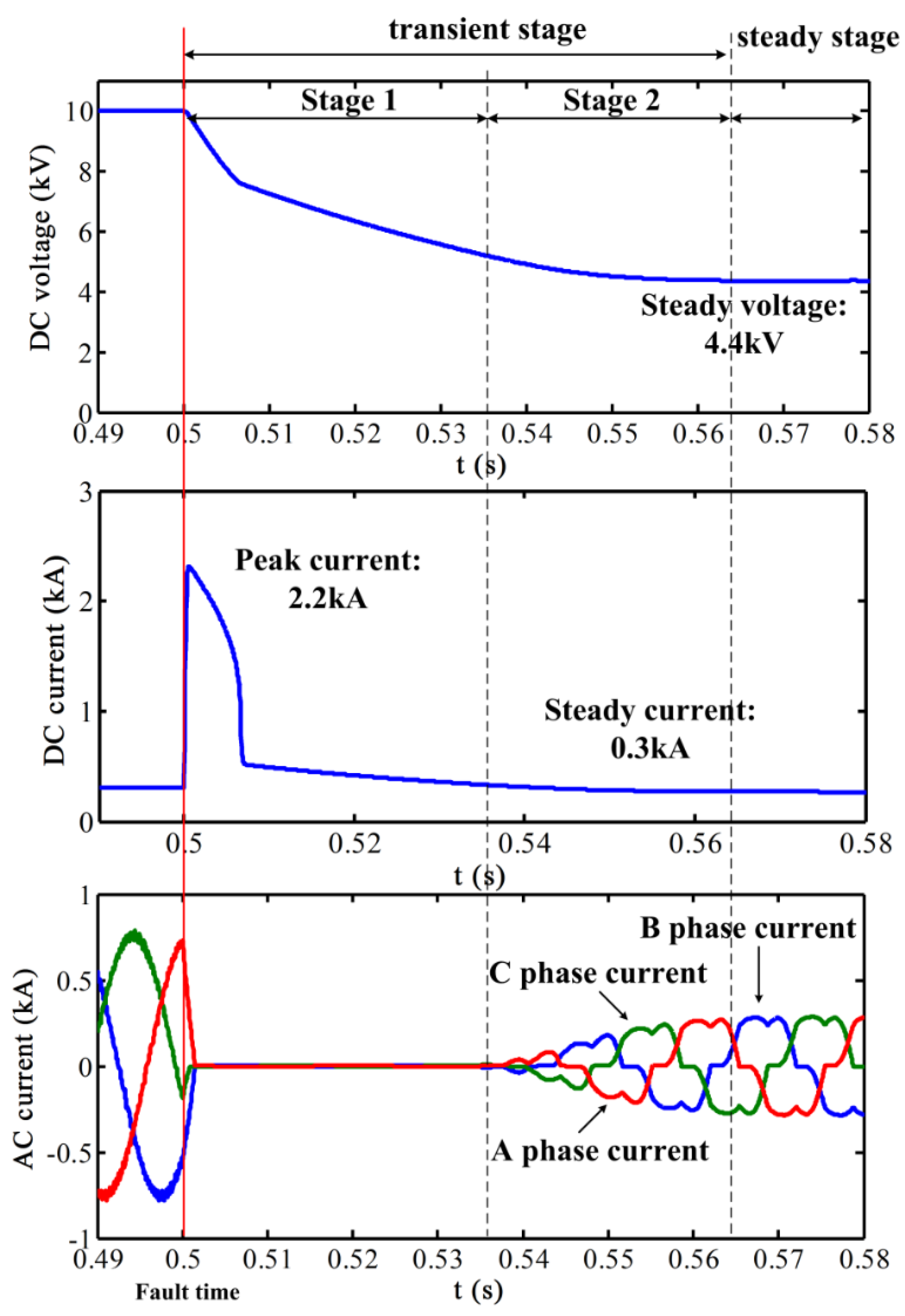
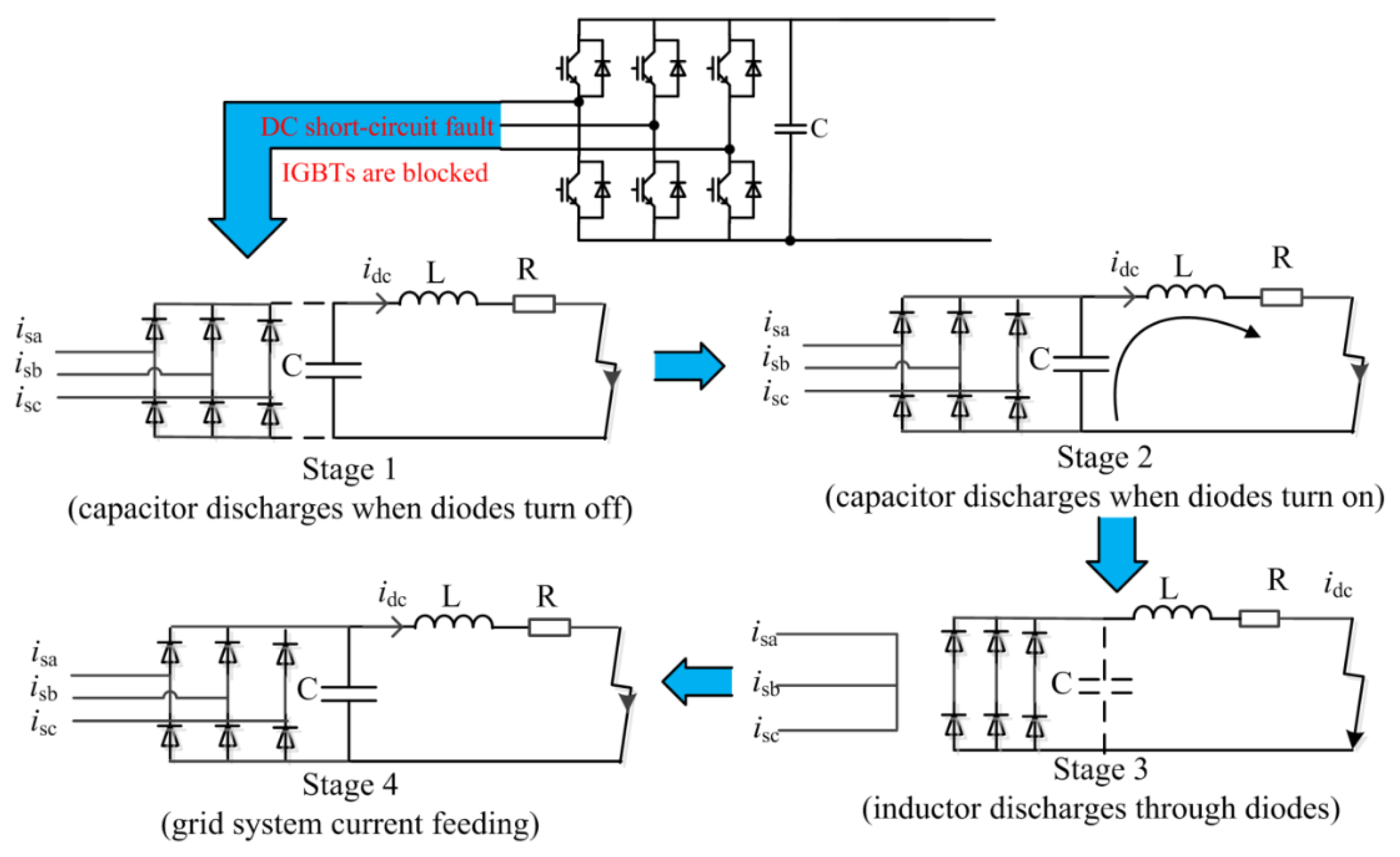
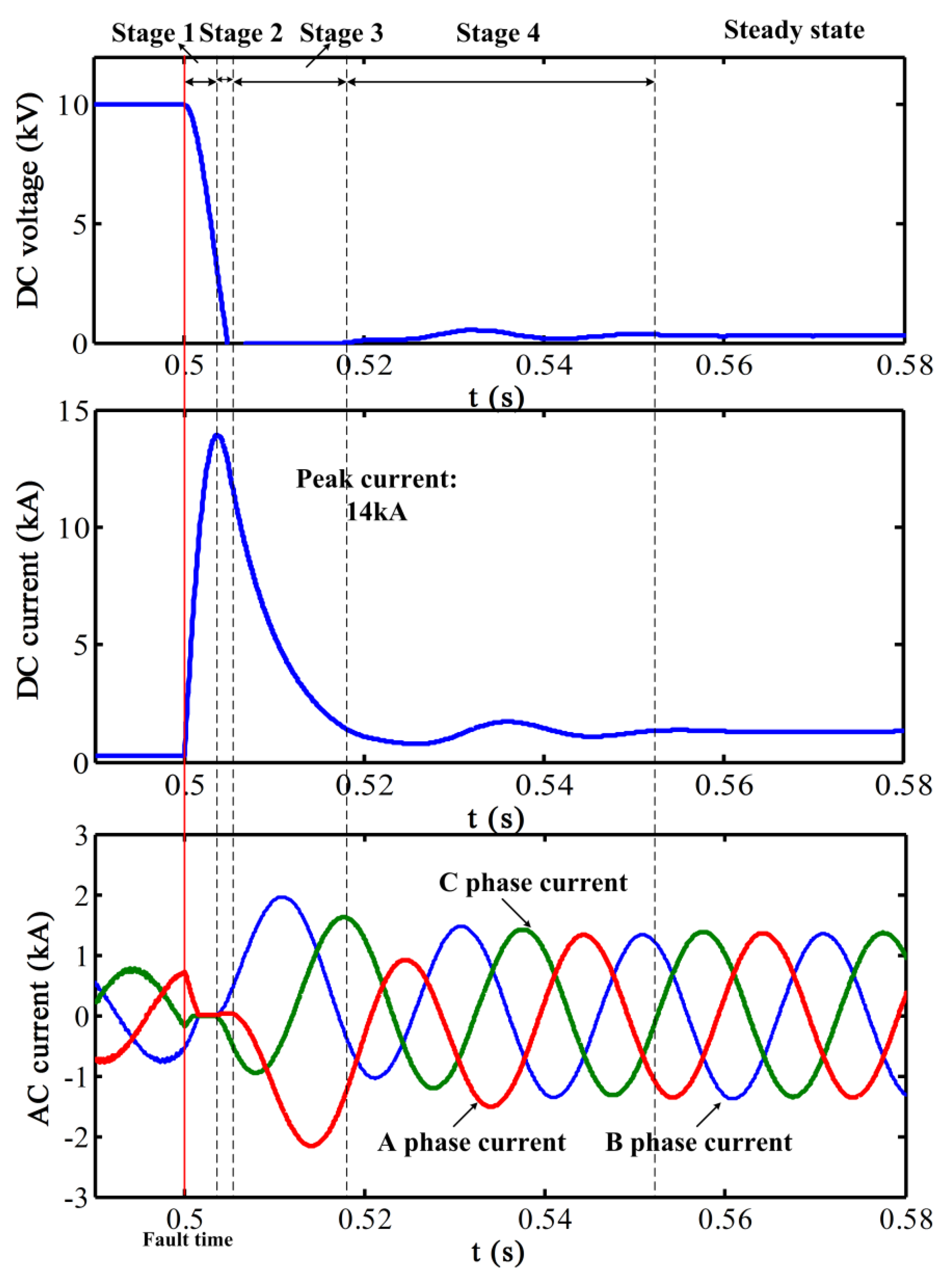
3.1. The Transient State of the DC Short-Circuit Fault with the Resistive SFCL

Stage 1: In the initial period of the fault, when the resistive SFCL is included and the IGBTs are blocked, the capacity, the cable and the SFCL compose the discharge circuit on the DC side. During this period, the voltage begins to decrease, and the DC current will rise to the maximum, then decrease. The equivalent circuit is shown in Figure 6.
Figure 6. The equivalent circuit of the VSC in the initial phase of the fault.
Energies 08 04839 g006
According to the circuit, the voltage and current of the DC side can be calculated by:
{ u dc = ( R + R SFCL ) i dc + L d i dc d t i dc = C d u dc d t
where idc is the current of the circuit; udc is the voltage of the capacitor; C is the capacity; R and L are the equivalent parameters of the cable from the exit of the VSC to the fault position; RSFCL is the resistance of the SFCL, which changes to nonlinear. Additionally, it is easy to know that the rate of descent of the voltage and peak current reduces greatly. The fault waveforms of Stage 1 are shown in Figure 5.
Stage 2: With the decrease of the DC voltage, the diodes start to turn on after the DC voltage is less than the AC voltage. The AC current begins to rise from zero. Then, the fault reaches the steady state gradually. The equivalent circuit at this stage is the same as the circuit in the steady state, which is shown in Figure 7. However, the discharge of the capacitor plays a major role at this stage. Additionally, the fault waveform of Stage 2 is shown in Figure 5.
Figure 7. The uncontrolled rectifier.
Energies 08 04839 g007

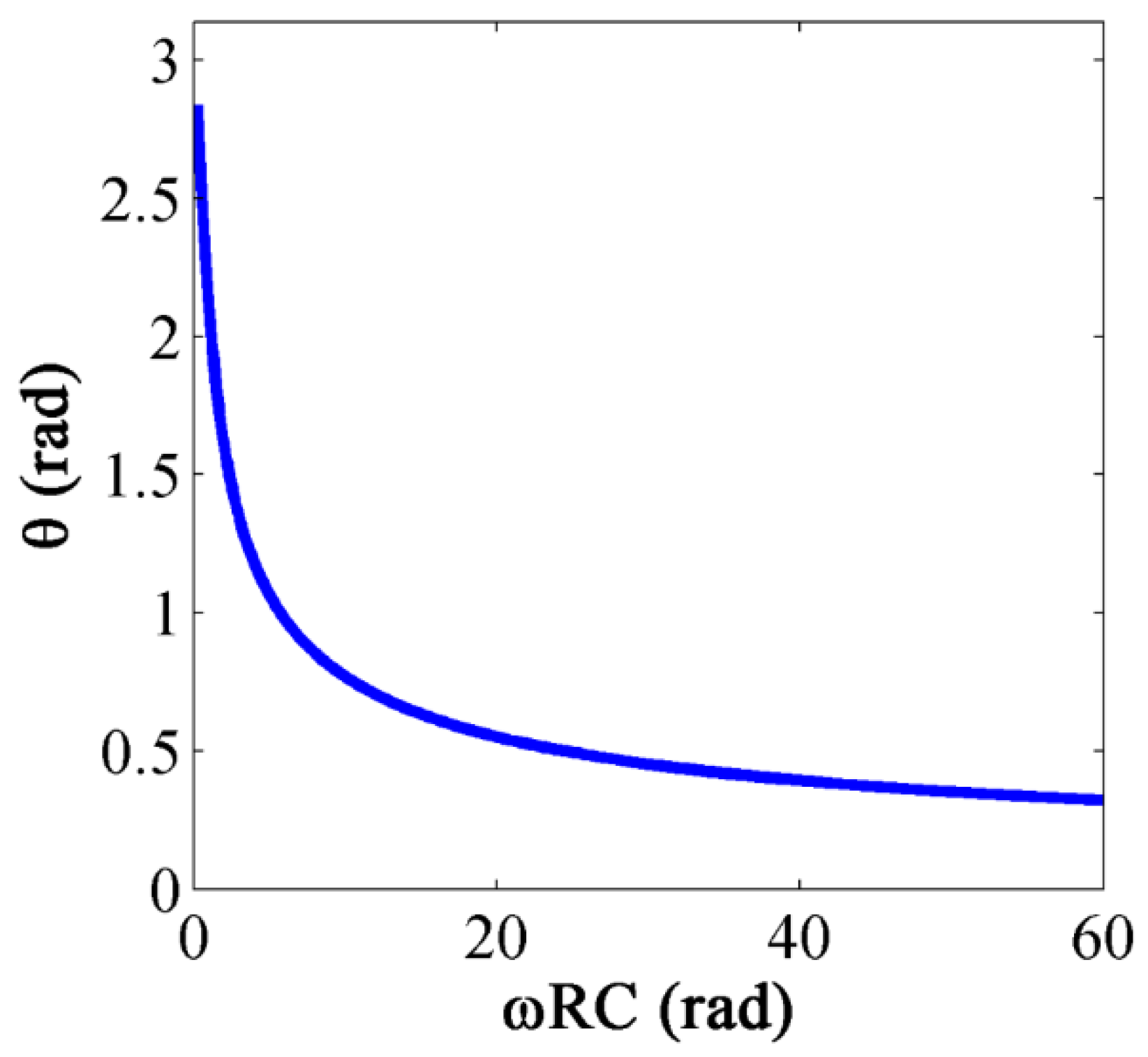
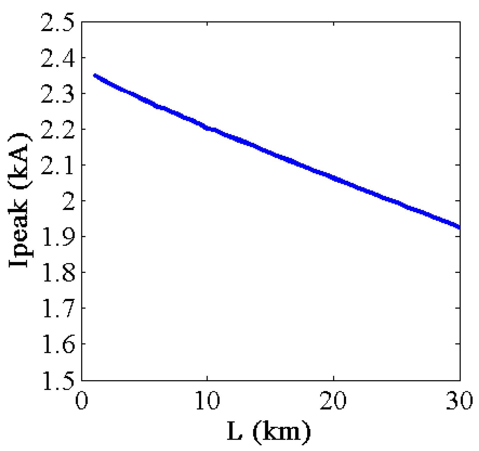
3.2. The Steady State of the DC Short-Circuit Fault with the Resistive SFCL

In the steady state, the VSC changes into an uncontrolled rectifier, as shown in Figure 7. The output voltage is impacted by the flow angle of the diodes. Additionally, the voltage changes between 2.34 U and 2.45 U, where U is the RMS value of the phase voltage of the AC system.
Because the resistance of the SFCL is much greater than the impedance of the cable, the analysis can be done ignoring the inductance. Then, the flow angle (θ) of the diodes is influenced by ωRC, and the relationship is shown in Figure 8.
Figure 8. The flow angle (θ) versus ωRC.
Energies 08 04839 g008
From Figure 8, it is known that the flow angle (θ) will decrease, with the increase of ωRC. The critical condition is ω R C = 3 . When ω R C > 3 , the AC current of the uncontrolled bridge rectifier will be discontinuous, as shown in Figure 5. With the large increase of the resistance in the fault circuit, the current in the steady state may be close to or less than the value in the normal condition. Additionally, in the steady state of the fault, the voltage increases greatly compared with the condition that the SFCL is not installed. On the other hand, the current in the steady state of the fault cannot be used for protection; otherwise, the protection will be incorrectly tripped.

4. Protection Principle and Verification

4.1. Transient Current Protection and Its Coordination

Overcurrent protection using the peak current is widely used in the DC distribution system. As we know, before the integration of the SFCL, the overcurrent protection using the peak current could coordinate very well [16]. It can satisfy the requests for protection. However, after the integration of the SFCL, the difference among the peak currents of different fault positions becomes little. In this situation, if we still apply the overcurrent protection, the reliability coefficient will be too small to satisfy the request for sensitivity and reliability. Therefore, the overcurrent protection needs to be improved.
In this paper, it is assumed that the fault resistance of the DC short-circuit fault between the cables is very small. According to the analysis above, we can get the relationship between the fault position and peak current, as shown in Figure 9. If the SFCL is included, the peak current has an approximately linear relationship with the position of the fault. However, the peak current changes a little with respect to the increasing of the distance of the fault. However, the time that the current takes to reach the maximum varies greatly when a fault happens at different positions, as shown in Figure 10. Then, if the ratio of the peak current to the time is used for the protection, as shown in Figure 11, the sensitivity and reliability could be ensured.
Figure 9. Peak currents of different fault positions.
Energies 08 04839 g009
Figure 10. The time that the current takes to reach the peak versus the fault position.
Energies 08 04839 g010
Figure 11. The ratio of the peak current to the time versus the fault position.
Energies 08 04839 g011

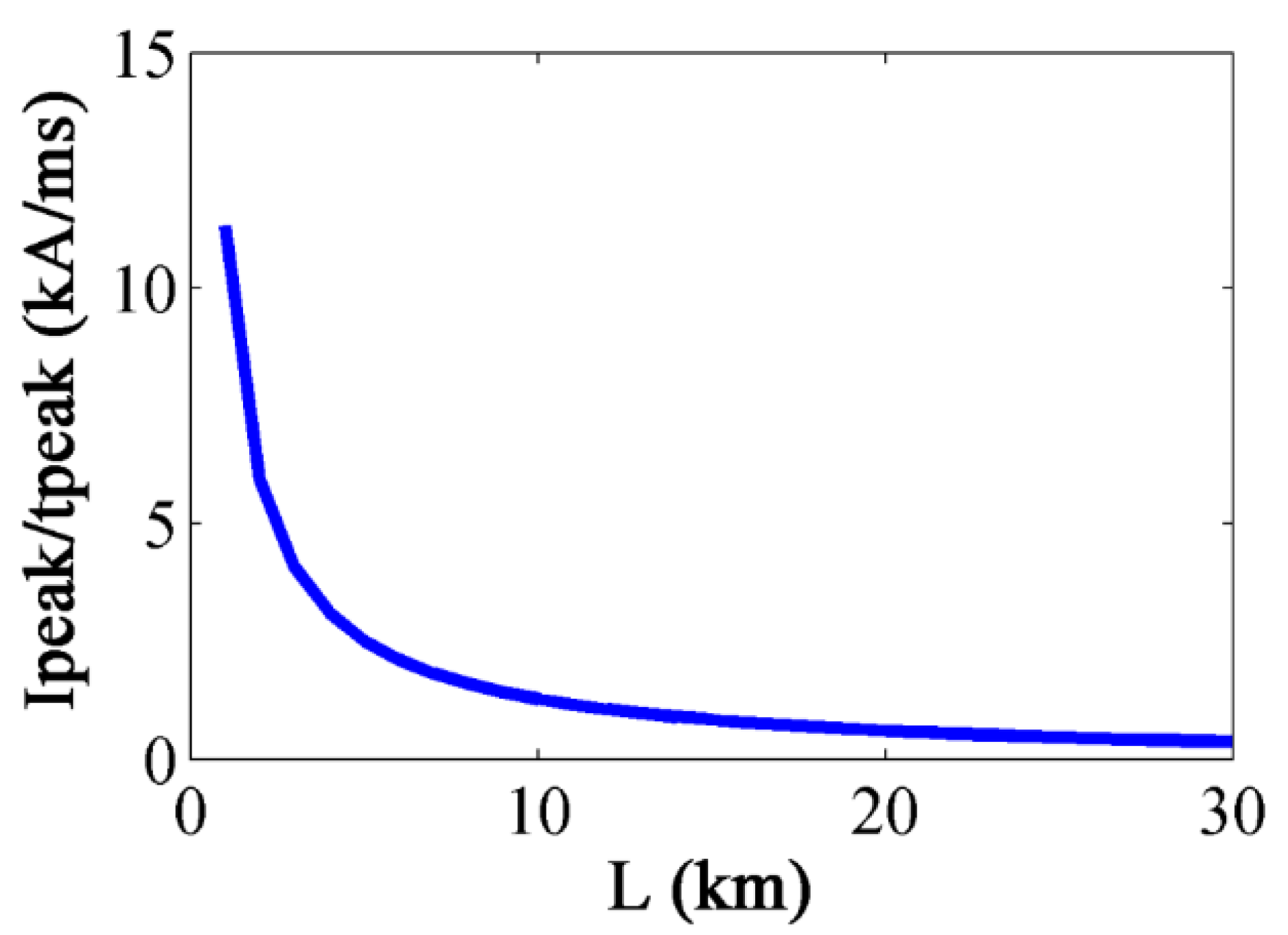
4.1.1. Transient Current Protection

Under the condition that the SFCL is installed, transient current protection is set according to the principle that the threshold is above the ratio of Ik peak end 1 (the peak of the short circuit current at the end of the line) to ∆tk peak end 1 (the time that the current takes to reach the maximum from the beginning of the fault). The operating criterion is:
I peak Δ t > ( I peak Δ t ) set 1 I
The threshold is:
( I peak Δ t ) set 1 I = K rel I × I k peak end 1 Δ t k peak end 1
where Ipeak is the maximum of the short circuit current during the fault; ∆t is the time that the current takes to reach the maximum from the start of the fault and K rel I is the reliability coefficient, which can be 1.2–1.3. Therefore, transient current protection can only protect about 80% or less of the line. However, the protection will operate without delay once the ratio exceeds the threshold.

4.1.2. Time-Limit under Voltage Protection Started by the Transient Current

Time-limit overcurrent protection coordinates with the downstream line by the time delay. The time delay can be 0.1 s or more in the DC system [16], considering the coordination with the downstream line and the operation time that the DC circuit breaker takes. However, when the SFCL is installed, the current has already been in the steady state at 0.1 s, and the value is close to the normal value after the fault. Therefore, traditional time-limited overcurrent protection cannot be applied directly to the DC system with the SFCL.
However, the DC voltage will decrease to a relatively low level at 0.1 s after the fault. When the resistive SFCL is installed, the voltage in the steady state changes little with the change of the fault position. Therefore, the under voltage protection alone cannot ensure the selectivity. Then, the transient current protection is combined with the under voltage protection, called the time-limit under the voltage protection started by the transient current. This kind of protection still protects the whole line and does not exceed the range of the transient current protection of the downstream line. It coordinates with the downstream line by a time delay. The starting value is the threshold of the transient current protection, and it can guarantee the selectivity of protection. After the time delay, whether the breaker operates is decided by the under voltage protection. The operating criterion is:
( I peak Δ t > ( I peak Δ t ) set 1 II ) ( t = t set 1 II ) ( U dc < U set 1 II )
The threshold is:
( I peak Δ t ) set 1 II = K rel II × ( I peak Δ t ) set 2 I = K rel II × K rel I × ( I k peak end 2 Δ t k peak end 2 )
t set 1 II = t 2 I + Δ t
U set 1 II = K u rel II × U N
where ( I peak / Δ t ) set 1 II is the starting value of the under voltage protection; ( I peak / Δ t ) set 2 I is the threshold of the transient current protection of the downstream line; K rel II is the reliability coefficient, which can be 1.1–1.2; U set 1 II is the threshold of the under voltage protection; UN is the rated K u rel II is the reliability coefficient; K u rel II = 0.5 0.6 , t 2 I is the inherent opening time of the transient current protection and ∆t is the time delay, always ∆t = 0.1–0.3 s.

4.2. Case Study

A 10-kV DC distribution system with the resistive SFCL is simulated by PSCAD/EMTDC. The structure of the system is shown in Figure 12. It is assumed that DC short-circuit fault occurs at 0.5 s in the different positions of the DC side. The fault resistance is 0.001 Ω. Each of the lines in the system is 10 km long. The equivalent parameter of the line is R = 0.078 Ω/km and L = 0.48 mH/km. When the system operates in the normal condition, the currents that go through each line are Iline1 = 0.35 kA, Iline2 = 0.252 kA and Iline3 = 0.157 kA.
Figure 12. The structure of the DC distribution, including the SFCL.
Energies 08 04839 g012
According to the analysis above, the thresholds of protection are listed in Table 1. Because Line 3 is the last section of the transmission line, traditional overcurrent protection can be applied for Line 3. Therefore, the threshold can be several times the load current, and the instantaneous overcurrent protection protects the whole line. In this situation, the time-limited overcurrent protection is the backup protection of Line 3. Then, the principle of the protection mentioned above is verified in this system, and the result is listed in Table 2.
Table 1. The thresholds of protection.
Line ParametersThresholds
Line1 (CB1)Itransient current threshold1.424 (kA/ms)
IItransient current threshold0.812 (kA/ms)
under voltage threshold5.0 (kV)
time delay threshold0.2 (s)
Line2 (CB2)Itransient current threshold0.738 (kA/ms)
IItransient current threshold0.496 (kA/ms)
under voltage threshold5.0 (kV)
time delay threshold0.2 (s)
Line3 (CB3)Iinstantaneous overcurrent threshold1.5 (kA)
IItime-limit overcurrent threshold1.5 (kA)
time delay threshold0.2 (s)
Table 2. The action situation of each CB.
LineFault Location (Percentage of the Line)The Action of Breakers (Time for Receiving Trip Instruction) (s)
CB1CB2CB3
Line130%0.5010##
80%0.5017##
100%0.7021##
Line230%#0.5027#
80%#0.5034#
100%#0.7038#
Line330%##0.5026
80%##0.5033
100%##0.5039
Note: # is defined as that the circuit breaker (CB) of the Line will not operate.
From the result, it can be seen that the presented protection principle could clear the fault quickly and accurately. The transient current protection can protect about 80% of the length of the section. Additionally, it operates without a time delay. With the increasing of the distance of the fault, the rising of current slows down. Therefore, the operation time of the transient current protection becomes longer, but still operates very quickly. On the other hand, the time-limited under voltage protection started by the transient current can protect the whole length of the line with a time delay. It can operate at about 0.2 s or more after the fault. This kind of protection may operate slowly, but it can guarantee the selectivity between the upstream line and the downstream line.
Therefore, for the DC distribution system, including the SFCL, this principle of protection can operate within a short time for the feeder faults, and the coordination of the upstream and downstream protective relays is ensured.

5. Conclusions

A resistive SFCL has good performance for current limiting in the DC distribution system. It is suitable for a system with a high fault current and a high current rising speed. However, the integration of the SFCL has a serious influence on the coordination of the protection. In this paper, the influence of the SFCL on the protection and the fault characteristic is analyzed in detail. Then, the transient current protection is presented, and the time-limited under voltage protection started by the transient current is proposed. Finally, the principle of the protection is verified in PSCAD/EMTDC. The result demonstrates that this principle of protection can ensure the coordination of the upstream and downstream protective relays. Nevertheless, a DC short-circuit fault with fault resistance is not considered in this paper, which would be the main work in the future.

Acknowledgments

This work was supported in part by the National Natural Science Foundation of China under Grant 51207103, by the Tianjin Municipal Natural Science Foundation under Grant 14JCYBJC21000, by the Innovation Foundation of Tianjin University under Grant 2014XRG-0118, by the Specialized Research Fund for the Doctoral Program of Higher Education for New Teacher under Grant 20120032120085 and by National High Technology Research and Development (863 program) under Grant 2015AA050102.

Author Contributions

Shimin Xue researched the protection principle and drafted the article. Feng Gao provided the results of the simulation. Valuable comments on the first draft were received from Feng Gao, Wenpeng Sun and Botong Li. All four were involved in revising the paper.

Conflicts of Interest

The authors declare no conflict of interests.

References

  1. Starke, M.R.; Tolbert, L.M.; Ozpineci, B. AC vs. DC distribution: A loss comparison. In Proceedings of the IEEE/PES TDCE, Chicago, IL, USA, 21–24 April 2008; pp. 225–231.
  2. Kakigano, H.; Nomura, M.; Ise, T. Loss evaluation of DC distribution for residential houses compared with AC system. In Proceedings of the IPEC, Sapporo, Japan, 21–24 June 2010; pp. 480–486.
  3. Mahmoodi, M.; Gharehpetian, G.B.; Abedi, M. A suitable control strategy for source converters and a novel load-generation voltage control scheme for DC voltage determination in DC distribution systems. In Proceedings of the IPEC, Putra Jaya, Malaysia, 28–29 November 2006; pp. 363–367.
  4. Starke, M.R.; Li, F.; Tolbert, L.M.; Ozpineci, B. AC vs. DC distribution: maximum transfer capability. In Proceedings of the IEEE PES, Pittsburgh, PA, USA, 20–24 July 2008; pp. 922–927.
  5. Sannino, A.; Postiglione, G.; Bollen, M.H.J. Feasibility of a DC network for commercial facilities. IEEE Trans. Ind. Appl. 2003, 39, 1499–1507. [Google Scholar] [CrossRef]
  6. Yang, J.; Fletcher, J.E.; O’ Reilly, J. Short-circuit and ground fault analyses and location in VSC-based DC network cables. IEEE Trans. Ind. Electron. 2012, 59, 3827–3837. [Google Scholar] [CrossRef]
  7. Khan, U.A.; Hwang, J.-S.; Seong, J.-K.; Lee, B.-W. Application and positioning analysis of a resistive type Superconducting Fault Current Limiter in AC and DC microgrids using Simulink and SimPowerSystem. In Proceedings of the ICEPE-ST, Xi’an, China, 23–27 October 2011; pp. 348–351.
  8. Manohar, P.; Ahmed, W. Superconducting Fault Current Limiter to mitigate the effect of DC Line fault in VSC-HVDC system. In Proceedings of the EPSCICON, Thrissur, Kerala, India, 3–6 January 2012; pp. 1–6.
  9. Lee, J.-G.; Khan, U.-A.; Hwang, J.-S.; Seong, J.-K.; Shin, W.-J.; Park, B.-B.; Lee, B.-W. Assessment on the influence of resistive superconducting fault current limiter in VSC-HVDC system. Phys. C. 2014, 504, 163–166. [Google Scholar] [CrossRef]
  10. Hwang, J.-S.; Khan, U.A.; Shin, W.-J. Validity analysis on the positioning of superconducting fault current limiter in neighboring AC and DC microgrid. IEEE Trans. Appl. Supercond. 2013, 23. [Google Scholar] [CrossRef]
  11. Ciezki, J.G.; Ashton, R.W. Selection and stability issues associated with a navy shipboard DC zonal electric distribution system. IEEE Trans. Power Deliver. 2000, 25, 665–669. [Google Scholar] [CrossRef]
  12. Tang, L. Control and Protection of Multi-Terminal DC Transmission Systems Based on Voltage-Source Converters. Ph.D. Thesis, McGill University, Montreal, QC, Canada, 2003. [Google Scholar]
  13. Mesute, B.; Nikhil, R.M. Overcurrent protection on voltage-source-converter based multi-terminal DC distribution systems. IEEE Trans. Power Deliver. 2007, 22, 406–411. [Google Scholar] [CrossRef]
  14. Tang, L.; Ooi, B.-T. Locating and isolating DC faults in multi-terminal DC systems. IEEE Trans. Power Deliver. 2007, 22, 1877–1884. [Google Scholar] [CrossRef]
  15. Salonen, P.; Nuutinen, P.; Peltoniemi, P. LVDC distribution system protection: Solutions, implementation and measurements. In Proceedings of the EPE, Barcelona, Spain, 8–10 September 2009; pp. 1–10.
  16. Xue, S.M.; Chen, C.C.; Jin, Y.; Li, Y.L.; Li, B.T.; Wang, Y. Protection for DC distribution system with distributed generator. J. Appl. Math. 2014, 2014. [Google Scholar] [CrossRef]
  17. Duan, P.; Xie, K.-G.; Zhang, L.; Rong, X. Open-switch fault diagnosis and system reconfiguration of doubly fed wind power converter used in a microgrid. IEEE Trans. Power Electron. 2011, 26, 816–821. [Google Scholar] [CrossRef]
  18. Choi, U.-M.; Jeong, H.-G.; Lee, K.-B.; Blaabjerg, F. Method for detecting an open-switch fault in a grid-connected NPC inverter system. IEEE Trans. Power Electron. 2012, 27, 2726–2739. [Google Scholar] [CrossRef]
  19. De Sousa, W.T.B.; Polasek, A.; Silva, F.A.; Dias, R.; Rio de Janeiro, B. Simulation and tests of MCP-BSCCO-2212 superconducting fault current limiters. IEEE Trans. Appl. Supercond. 2012, 22. [Google Scholar] [CrossRef]
  20. Langston, J.; Steurer, M.; Woodruff, S.; Baldwin, T.; Tang, J. A generic real time computer simulation model for superconducting fault current limiters and its applications in system protection studies. IEEE Trans. Appl. Supercond. 2005, 15, 2090–2093. [Google Scholar] [CrossRef]

