Article

A New Optimization Method for Centrifugal Compressors Based on 1D Calculations and Analyses

Department of Thermal Engineering, Tsinghua University, Beijing 100084, China
*
Author to whom correspondence should be addressed.
Energies 2015, 8(5), 4317-4334; https://doi.org/10.3390/en8054317
Submission received: 24 February 2015 / Revised: 30 March 2015 / Accepted: 15 April 2015 / Published: 12 May 2015

Abstract

:
This paper presents an optimization design method for centrifugal compressors based on one-dimensional calculations and analyses. It consists of two parts: (1) centrifugal compressor geometry optimization based on one-dimensional calculations and (2) matching optimization of the vaned diffuser with an impeller based on the required throat area. A low pressure stage centrifugal compressor in a MW level gas turbine is optimized by this method. One-dimensional calculation results show that D3/D2 is too large in the original design, resulting in the low efficiency of the entire stage. Based on the one-dimensional optimization results, the geometry of the diffuser has been redesigned. The outlet diameter of the vaneless diffuser has been reduced, and the original single stage diffuser has been replaced by a tandem vaned diffuser. After optimization, the entire stage pressure ratio is increased by approximately 4%, and the efficiency is increased by approximately 2%.

1. Introduction

Small gas turbines have been widely used in small aircraft, vehicles, distributed energy systems and other energy applications. A centrifugal compressor has been generally used in small gas turbines because of the high single stage pressure ratio, simple structure, long life and other favorable characteristics. Therefore, research on design optimization methods for centrifugal compressors has important significance for small gas turbine development. The centrifugal compressor has an axial inlet and a radial outlet, so the interactions between the impeller and diffuser exhibit strong three-dimensional characteristics. At present, the design of centrifugal compressors is based on 1D calculations and analyses. 1D calculations are a very important tool for designers; they can be used to calculate the geometric parameters according to the requirements at very early development stages and during the optimization process. These calculations can quickly determine whether the geometrical parameters are reasonable.
1D analysis has been persistently developed in the past several decades, and the main methods used in the prediction are Single-Zone modeling and Two-Zone modeling. The Single-Zone model assumes that the flow through the impeller passage is uniform, so there is one flow path in the impeller. Galvas [1] developed a Single-Zone model for calculating the off-design performance of centrifugal compressors with channel diffusers. Aungier [2] provided a comprehensive mean streamline aerodynamic performance prediction procedure for centrifugal compressor stages, and the results match the experimental results for a turbocharger compressor with pressure ratio up to 3.5. Oh [3] extensively tested the loss models previously published in the literature and found an optimum set of empirical loss models for a reliable performance prediction of centrifugal compressors. Two-Zone modeling was developed by Japikse [4]; it assumes that a ‘jet-wake’ structure exists in the impeller passage.
Shape optimization is also an important method in centrifugal compressor design. Mengistu [5] represented the turbine blade shape with a MRATD model, which is a low-order representation that describes the blade profile using a maximum of 17 aerodynamic design parameters. This representation is then used in an optimization scheme to accomplish a certain optimization objective. Rossetti [6] presented an optimum design procedure for an aerodynamic radial diffuser aiming at achieving the best compromise between flow deflection, static pressure recovery, and total pressure loss. Although many designers try to improve the efficiency of centrifugal compressor by shape optimization, the matching of the vaned diffuser with the impeller has an important influence on the efficiency of centrifugal compressor. Klassen [7] tested a centrifugal compressor with a backswept bladed impeller and a vaned and vaneless diffuser, and it is found that better matching of impeller and diffuser can improve peak stage efficiency. Tamaki [8] tested centrifugal compressors with 11 differenet vaned diffusers in order to investigate change of surge flow rate with different diffuser throat areas. Caser [9] proposed a method to judge whether the impeller and the vaned diffuser match, which has been validated by comparison with a wide range of compressor designs from many sources. Cumpsty [10] even believes that mismatching is a far more common cause of poor performance with high pressure ratio machines than the diffuser details and the impeller vane shapes. However, the above researches did not try to optimize the performance of the centrifugal compressor by improving the matching of the vaned diffuser with the impeller.
This study, proposes an optimization method for centrifugal compressors based on 1D calculations and analyses. The centrifugal compressor will first be analyzed by Single-Zone modeling based on the iSIGHT platform to find the best geometric parameters. Then, the matching of the vaned diffuser with the impeller will be examined, according to which the vaned diffuser is optimized. The low pressure stage centrifugal compressor in a MW level gas turbine is optimized by this method. After optimization, the entire stage performance is greatly improved.

2. Review of Loss Model

In the past several decades, the empirical loss model for centrifugal compressor has been persistently developed. Each loss model has one or more correlations. This section will review the loss models in the literature.

2.1. Impeller Loss Model

2.1.1. Incidence Loss

Incidence loss is caused by the direction of the gas flow diffusing from the blade angle, which greatly affects the compressor performance characteristics at off-design conditions. Galvas [1] developed an equation assuming that the relative velocity component normal to the optimum incidence angle is lost:
Δ h i n c = W L 2 2 C p
where:
W L = W m 1 sin | β o p t β 1 m |
Conard [11] suggested that:
Δ h i n c = f i n c W θ 1 2
where f i n c is the incidence coefficient in the range of 0.5 to 0.7.
Aungier [2] also developed an equation for centrifugal compressors with an axial inlet. The incidence loss is computed by:
Δ h i n c = 0.4 ( W m 1 C m 1 sin β 1 b ) 2
Equation (4) is applied at the hub, shroud, and mean surfaces.

2.1.2. Blade Loading Loss

Boundary layer growth in the impeller is highly dependent on the diffusion of the working fluid internal to the impeller itself. Jansen [12] and Coppage [13] proposed an equation for calculating the diffusion factor of the impeller:
D f = 1.0 W 2 W s 1 + 0.75 Δ h t h W 2 [ Z π ( 1 d s 1 d 2 ) + 2 d s 1 d 2 ]
With the diffusion factor calculated by this method, the blade loading loss was expressed as:
Δ h b l = 0.05 D f 2 u 2 2
Aungier [2] suggested that the blade loading loss should be computed as the mixing loss derived from the integrated difference between the average and the mass-averaged relative velocity squared for the distorted profiles:
Δ h b l = Δ W 2 48
where:
Δ W = 2 π d 2 u 2 I B Z L B

2.1.3. Skin Friction Loss

Skin friction losses are due to shear forces in the boundary layer. The loss model given by Jasen [12] is:
Δ h s f = 2 c f L B d H B ( W ¯ u 2 ) 2 u 2 2
W ¯ = 2 W 2 + W s 1 + W h 1 4
L B π 8 [ d 2 d s 1 + d h 1 2 b 2 + 2 L z ] ( 2 cos β s 1 + cos β h 1 2 + cos β 2 )
d H B d 2 = cos β 2 [ Z π + d 2 cos β 2 b 2 ] + 1 2 ( d s 1 d 2 + d h 1 d 2 ) ( cos β s 1 + cos β h 1 2 ) Z π + ( d s 1 + d h 1 d s 1 d h 1 ) ( cos β s 1 + cos β h 1 2 )
The equation suggested by Aungier [2] is same as Equation (8), where:
W ¯ 2 = W 1 2 + W 2 2 2

2.1.4. Disk Friction Loss

This specific loss is due to the shear forces between the impeller back face and the stationary surface. Daily and Nece [14] gave the correlation:
Δ h d f = f d f ρ ¯ d 2 2 u 2 3 16 m ˙
where f d f is a friction factor depending on the Reynolds number.
Galvas [1] used another equation to calculate the loss:
Δ h d f = 0.01356 ρ 2 m ˙ Re 0.2 d 2 2 u 2 3

2.1.5. Recirculation Loss

Recirculation loss results from the working fluid backflow into the impeller. The correlation suggested by Rodgers [15] is:
Δ h r e = 0.032 ( u 2 c m 1 ) 2 u 2 2
Jasen [12] suggested another equation to estimate the value of recirculation loss:
Δ h r e = 0.02 D f 2 cot α 2 u 2 2
Aungier [2] introduced the blade stall limit into the recirculation loss model to improve the previous model at the low flow region:
Δ h r e = ( D e q 2 1 ) ( W u 2 C m 2 2 cot β 2 ) ,     i f D e q > 2
Oh [3] employed a hyperbolic function in the recirculation loss model:
Δ h r e = 8 × 10 5 sinh ( 3.5 α 2 3 ) D f 2 U 2 2
Japikse [4] thought that prediction of the efficiency at flows of more than ±15% or 20% away from the design point was largely dominated by the empirical specification of the recirculation loss. Therefore, the use of a “bucket” model was suggested to account for the additional loss in off-design conditions. A “bucket” curve is a common approach that uses a piecewise parabola to fit the recirculation loss value. The “bucket” model suggested by Japikse is presented as follows:
Δ h r e = ( c 1 ( m ˙ m ˙ d e s i g n 1 ) 2 + b 1 ) u 2 2
where c 1 and b 1 are empirical coefficients. The model consisted of two pieces of second order curves, so the coefficient c 1 has two different values in different situations:
c 1 = { k 1 , m ˙ m ˙ d e s i g n 1 k 2 , m ˙ m ˙ d e s i g n > 1
where k 1 and k 2 are empirical coefficients.

2.1.6. Clearance Loss

Significant flow leakage occurs through the gap between the impeller and the casing resulting from the pressure difference between the pressure side and the suction side of the compressor. The correlation for this loss was given by Jasen [12]:
Δ h c l = f c l ( Δ n c l b 2 ) ( C θ 2 u 2 ) 4 π b 2 Z [ r s 1 2 r h 1 2 ( r 2 r s t ) ( 1 + ρ 2 / ρ 1 ) ] ( C θ 2 u 2 ) ( C m 2 u 2 )
The equation given by Aungier [2] is:
Δ h c l = m ˙ c l Δ P C L m ˙ ρ

2.1.7. Mixing Loss

The correlation suggested by Johnston and Dean [16] is:
Δ h m i x = 1 1 + tan 2 α 2 ( 1 ε w b * 1 ε w ) 2 C 2 2
Aungier [2] gave another equation to compute the mixing loss:
Δ h m i x = 1 2 ( W s e p W o u t ) 2 W s e p = W 2 ;    D e q 2 W s e p = W 2 D e q 2 ;    D e q > 2 W o u t 2 = ( C m 2 A 2 π d 2 b 2 ) 2 + W θ 2

2.2. Slip Factor

Due to the finite number of blades, the exit flow angle cannot be the same as the exit blade metal angle. Slip factor is one of the methods used to model the flow deviation. The equation given by Stodola [17] is:
μ = 1 π sin β 2 b Z ( 1 c r 2 cot β 2 b / u 2 )
Weisner [18] reviewed the slip factor calculations and gave his own correlation based on the analysis of a number of experiments:
σ = 1 cos β 2 b Z 0.7
Qiu [19] considered that the flow coefficient at the impeller exit was an important variable for the slip factor and suggested a new slip model:
σ = 1 F π cos β 2 b sin γ 2 Z F s 2 ϕ 2 4 cos β 2 b ( d β d m ) 2

2.3. Vaneless Diffuser Loss Model

Stanitz [20] suggested an equation to calculate loss in the vaneless diffuser:
Δ h v l d = C p T 02 [ ( P 3 P 03 ) ( γ 1 ) / r ( P 3 P 02 ) ( γ 1 ) / r ]

2.4. Vaneless Diffuser Loss Model

Aungier [21] gave a set of equation to calculate the loss in the vaned diffuser. The loss was divided in the vaned diffuser into the following types:
Incidence loss:
Δ h v i n = { 0.4 ( C 3 C 3 * ) i f C 3 < C 3 s 0.4 [ C 3 2 C 3 s 2 + ( C 3 s C 3 * ) 2 ] i f C 3 > C 3 s
Skin friction loss:
Δ h v s f = 0.5 C ¯ 2 L B d H
Choking loss:
Δ h v c h = { 0 ; X 0 1 4 C 3 2 U 2 2 [ 0.05 X + X 7 ] ; X > 0
Discharge blockage friction loss:
Δ h v B = 1 2 [ C 4 1 B 4 C 4 ] 2
Wake mixing loss:
Δ h v w = 1 2 ( C w a k e 2 C o u t 2 ) 2

3. Validation of the Loss Model

From the above review, it can be seen that there are many loss models for centrifugal compressor, some of which have two or more correlations. When a performance prediction is made, there are hundreds of combinations to be selected. Before the 1D analysis is completed, an optimum loss model should be chosen. A large number of researchers, including Galvas [1], Aungier [2], Oh [3], and Doustmohammadi [22], among others, have determined an optimum set of loss models. However, some critical factors have not been well considered. In this section, a new optimum set of loss models will be suggested according to the experimental data.
HPCC is a typical and well-known centrifugal compressor with a vaned diffuser. Its main specifications are shown in Table 1. Other information can be found in reference [23]. Its experimental data will be used to find the optimum set of loss models. The validation will be divided into two parts as follows: first, the loss model of the impeller and the vaneless diffuser will be discussed; then, the loss model of the vaned diffuser will be examined.
Table 1. Main specifications of HPCC.
HPCC impeller
Inlet total temperature (K)288.15
Inlet total pressure (Pa)101,325
Rotation speed (rpm)21,789
Mass flow (kg/s)4.54
Pressure ratio4

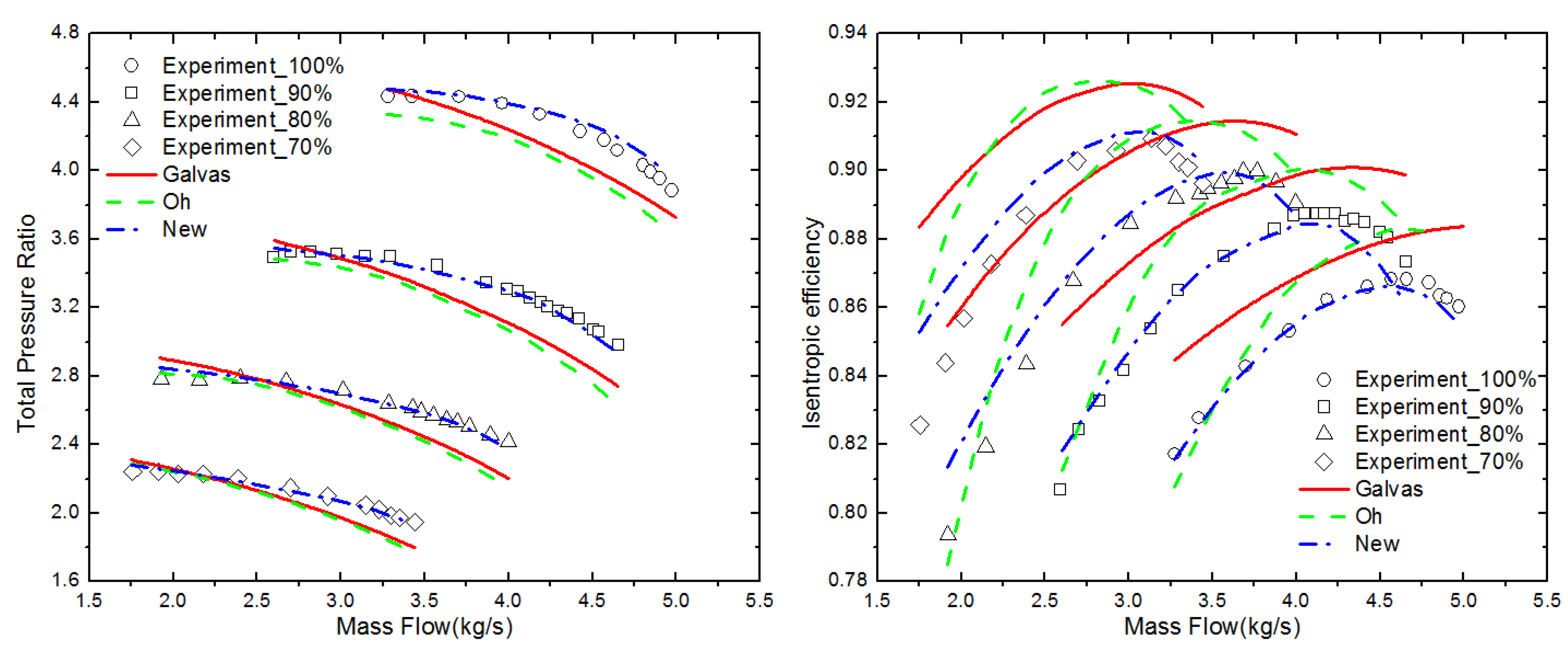
3.1. Validation of the Impeller and Vaneless Diffuser Loss Model

Two classical loss model combinations and the new loss model combination are shown in Table 2. Figure 1 shows the performance predictions computed by these three combinations for a HPCC impeller. It can see that the pressure ratio results of the new model are greatly improved at all rotational speeds, and the efficiency results of the new model also agree well with the experimental data
Table 2. Loss model combination.
LossesGalvasOhNew
IncidenceGalvas [1]Conrad [11]Aungier [2]
Skin frictionGalvas [1]Jasen [12]Jasen [11]
Blade loadingCoppage [12]Coppage [13]Coppage [13]
ClearanceNoneJasen [12]Jasen [12]
MixingNoneJohnston and Dean [16]Johnston and Dean [16]
Disk FrictionGalvas [12]Daily and Nece [14]Daily and Nece [14]
RecirculationJasen [13]Oh [3]Japikse [4]
Slip factorWiesner [18]Wiesner [18]Qiu [19]
Vaneless diffuser lossStanitz [24]Stanitz [24]Stanitz [24]
Figure 1. Performance prediction of HPCC impeller with a vaneless diffuser.
Energies 08 04317 g001

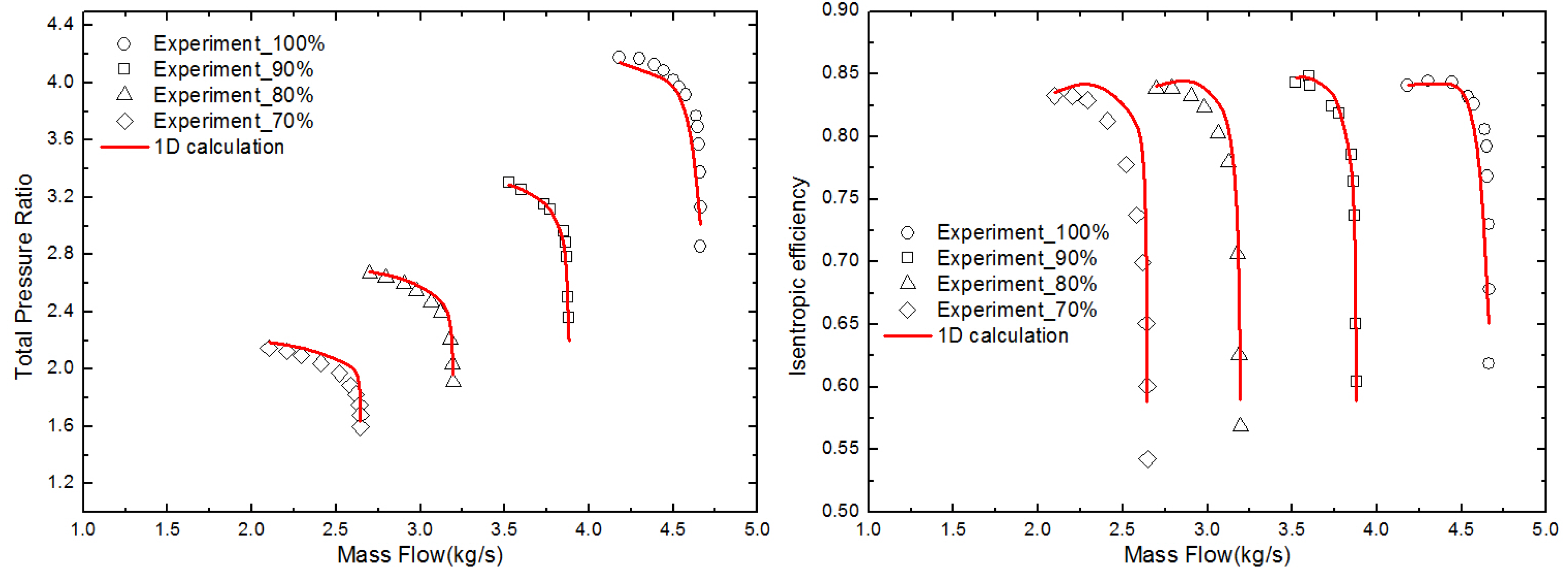
3.2. Validation of the Vaned Diffuser Loss Model

The loss model combination given by Aungier [21] is used to calculate the loss in the vaned diffuser. Comparisons of the 1D calculation results and the experiment data for the HPCC impeller with vaned diffuser are shown in Figure 2. It can be seen that the 1D calculation results agree well with the experimental data at 100% rotation speed. At off-design speeds and lower rotational speeds, larger errors occur between the 1D result and the experimental data. At 60% rotation speed, the error is greater than 20%. This may occur because the model proposed by Aungier is mainly aimed at the design condition loss calculation. In this study, only the centrifugal compressor performance is examined at the design condition using the 1D calculation, so the Aungier loss model meets the requirement.
Figure 2. Performance prediction of HPCC impeller with a vaned diffuser.
Energies 08 04317 g002

4. Optimization Results

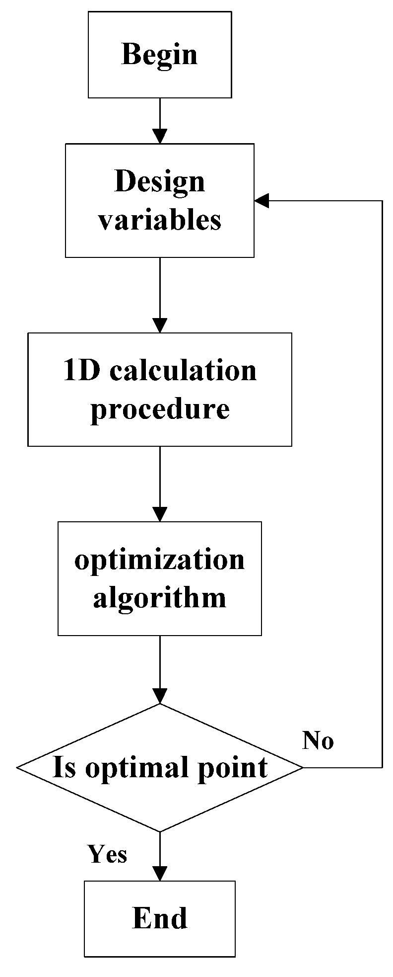
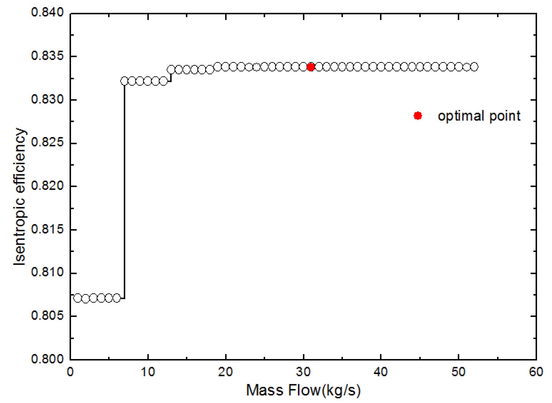
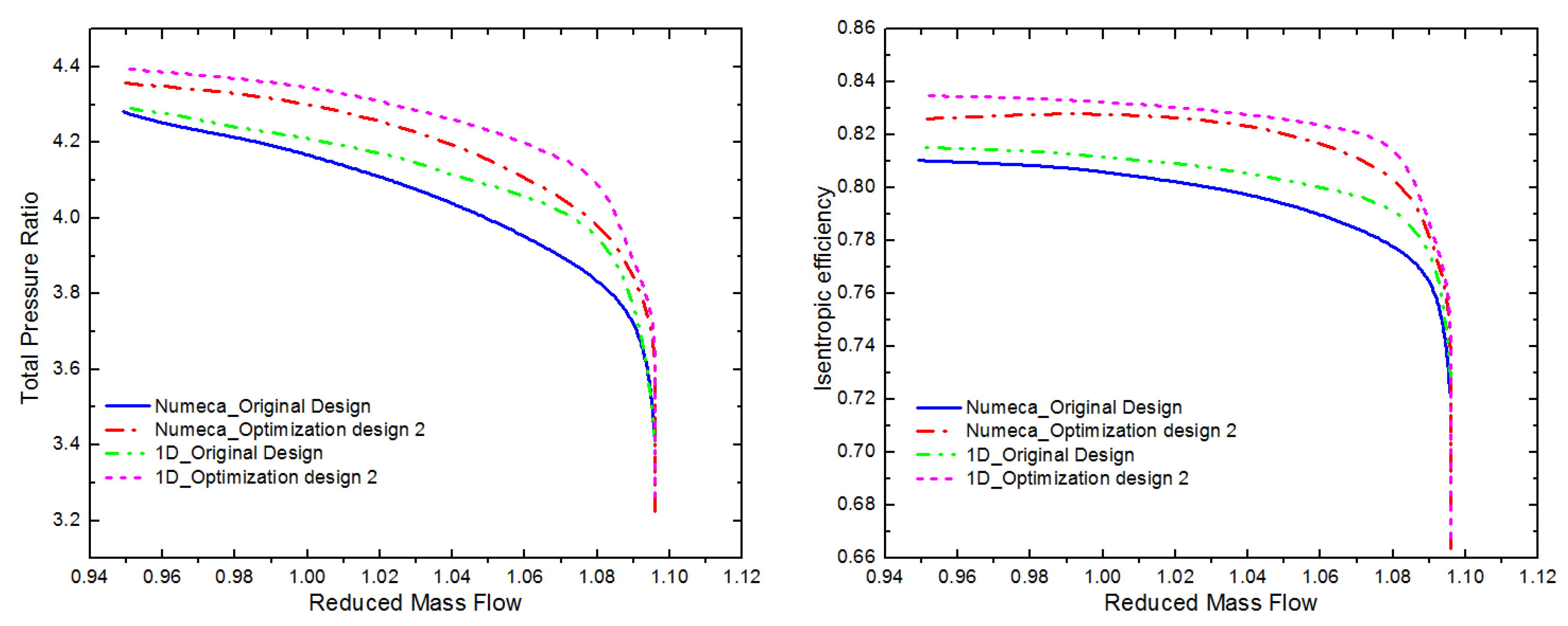
4.1. Results of the 1D Optimization Calculations

The structure of a MW level gas turbine is shown in Figure 3. The low stage centrifugal compressor is composed of an inlet guide vane, an impeller and a diffuser. Its geometric structure is shown in Figure 4.
Figure 3. Structure of a MW level gas turbine.
Energies 08 04317 g003
Figure 4. Geometric structure of a low stage centrifugal compressor.
Energies 08 04317 g004
The geometric parameters of the centrifugal compressor are considered to be design variables, and the efficiency of the entire stage is considered to be the objective function. The optimization is completed using iSIGHT commercial software by an adaptive simulated annealing algorithm. The optimization procedure is shown in Figure 5. Figure 6 shows the optimization history, which shows a ladder-like shape similar as the previous work which also used the ASA algorithm [24,25].
Figure 5. Optimization procedure.
Energies 08 04317 g005
Figure 6. Optimization history.
Energies 08 04317 g006
Table 3 shows the parameters comparison between the optimization design and the original design. In both designs, the efficiency at the impeller outlet is very high, at nearly 95%. However, at the outlet of the vaneless and vaned diffusers, the efficiency of the optimization design is much higher than in the original design. This is because the diameter ratio D3/D2 is too large in the original design, resulting in a loss increase in the vaneless diffuser that decreases the efficiency of the entire stage. In the optimization design, the diameter ratio D3/D2 is reduced to a proper value, the loss in the vaneless diffuser is significantly reduced, and the efficiency of the entire stage is obviously improved.

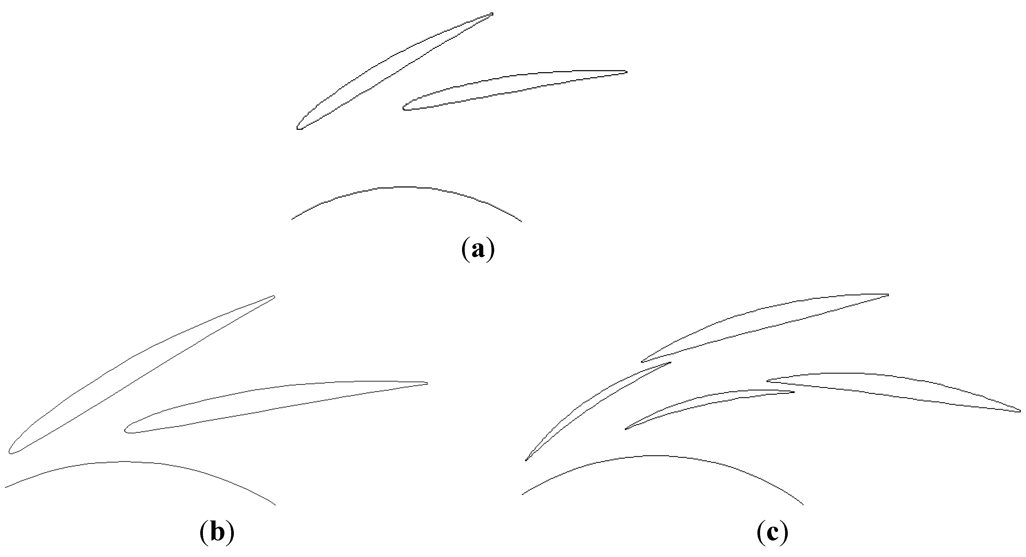
4.2. Redesign of the Vaned Diffuser

The 1D optimization results show that to improve the efficiency of a low pressure stage centrifugal compressor, the diameter ratio D3/D2 must be reduced. If D3/D2 is reduced by moving the original vaned diffuser toward the impeller, the throat area of the vaned diffuser will also decrease (as shown in optimization design 1 in Figure 7). The reduction of the vaned diffuser throat area will lead to the decrease of the vaned diffuser choke mass flow, which affect the matching of the diffuser and the impeller. To ensure that the performance of the entire stage will be improved after optimization, it is necessary to analyze the matching of the impeller and the vaned diffuser.
Table 3. Parameters comparison between the optimization design and the original design.
ParameterOriginal DesignOptimization Design
D 1 s (m)0.0820.075
D 1 t (m)0.2020.190
D 2 (m)0.3260.326
Lz (m)0.080.075
b 2 (m)0.01510.0158
D 3 (m)0.440.3586
D 4 (m)0.6010.601
D3/D21.341.10
η 2 94.87%95.15%
η 3 86.29%92.63%
η 4 81.09%83.38
Figure 7. Geometric structure of the vaned diffuser: (a) Original design; (b) Optimization design 1; (c) Optimization design 2.
Energies 08 04317 g007
Caser [9] proposed a method to judge whether the impeller and the vaned diffuser match. If the impeller and the vaned diffuser choke at the same time, the theoretical ratio of the impeller and the diffuser throat areas is:
A d * A i * = ( 1 + K 1 2 ( D 1 D 2 ) 2 M u 2 2 ) K + 1 2 ( K 1 ) ( 1 + ( K 1 ) λ M u 2 2 ) n + 1 2 ( n 1 )
Michae thought that a high performance of the centrifugal compressor is to be achieved, the design ratio of the impeller and the diffuser throat areas should be close to the theoretical value. In the original design, as seen in Table 4, the ratio of design A d * / A i * to theoretical A d * / A i * is 1.161.
Table 4. Ratio of the impeller and the diffuser throat areas.
Original designOptimization design 1Optimization design 2
( A d * / A i * ) d e s i g n ( A d * / A i * ) t h e o r y 1..1610.9221.043
This indicates that the choke mass flow of the vaned diffuser is larger than the impeller and that the impeller and the vaned diffuser do not match well. If the vaned diffuser is moved towards to the impeller (as shown in optimization design 1), the ratio of design A d * / A i * to theoretical A d * / A i * is reduced to 0.922. This leads to a sudden decrease of the throat area of the vaned diffuser, resulting in the reduction of the choke mass flow of the entire stage, which does not meet the design requirements. If the diameter ratio D3/D2 needs to be reduced without a decrease of the choke mass flow, the vaned diffuser should be redesigned. The original vaned diffuser is replaced by a tandem vaned diffuser. Its geometric structure is shown in Figure 7 (as shown in optimization design 2). Using the tandem diffuser, then the ratio of design A d * / A i * and theoretical A d * / A i * is reduced to 1.043, much close to 1. This indicates that the impeller and diffuser match very well. The throat area of the vaned diffuser is slightly larger than the impeller, which makes the choke mass flow of the optimization design remain consistent with the original design.
The original design and optimization design 2 are simulated by a 3-D CFD code Numeca. The grids are generated by AutoGrid. The grid number of the original design is 1,100,000 and the grid number of optimization design 2 is 1,400,000. An S-A turbulence model is employed. The inlet total temperature, total pressure and flow direction are given at the compressor inlet. A radial equilibrium equation is used at the outlet and the no slip wall is defined for the hub, casing and blade surfaces. 1D calculations are completed for comparison. The calculation results are shown in Figure 8.
Figure 8. Performance map of original design and optimization design 2.
Energies 08 04317 g008
Figure 9 shows the meridional streamline chart, which illustrates a large separation vortex in the vaneless diffuser due to large diameter ratio D3/D2 in the original design. The separation vortex in the vaneless diffuser also deteriorates the flow condition at the vaned diffuser inlet, which resultes in the large separation area in the vaned diffuser (Figure 10). In optimization design 2, as the diameter ratio D3/D2 decreases, the separation vortex disappears in the vaneless diffuser. The flow condition at the vaned diffuser inlet is also improved too. Therefore, there is no longer a separation area in the vaned diffuser.
Figure 9. Meridional streamline: (a) Original design; (b) Optimization design 2.
Energies 08 04317 g009
Figure 10. Streamline in the vaned diffuser at different span: (a) Original design; (b) Optimization design 2.
Energies 08 04317 g010

5. Conclusions

This paper presents an optimization design method for centrifugal compressors based on one-dimensional calculations and analyses. It consists of two parts: (1) centrifugal compressor geometry optimization based on one-dimensional calculations and (2) matching optimization of the vaned diffuser with the radial compressor impeller based on the required throat area. A low pressure stage centrifugal compressor in a MW level gas turbine is optimized by the method. The conclusions of the study are the follows:
(1)
A new set of loss model combinations is presented by reviewing the existing 1D loss models, which contains loss models of the impeller, vaneless diffuser and vaned diffuser. At design speeds, the 1D calculation results agree well with the experiment data; at off-design speeds, especially at low speeds, there is large difference betweent the 1D calculation results and the experiment data.
(2)
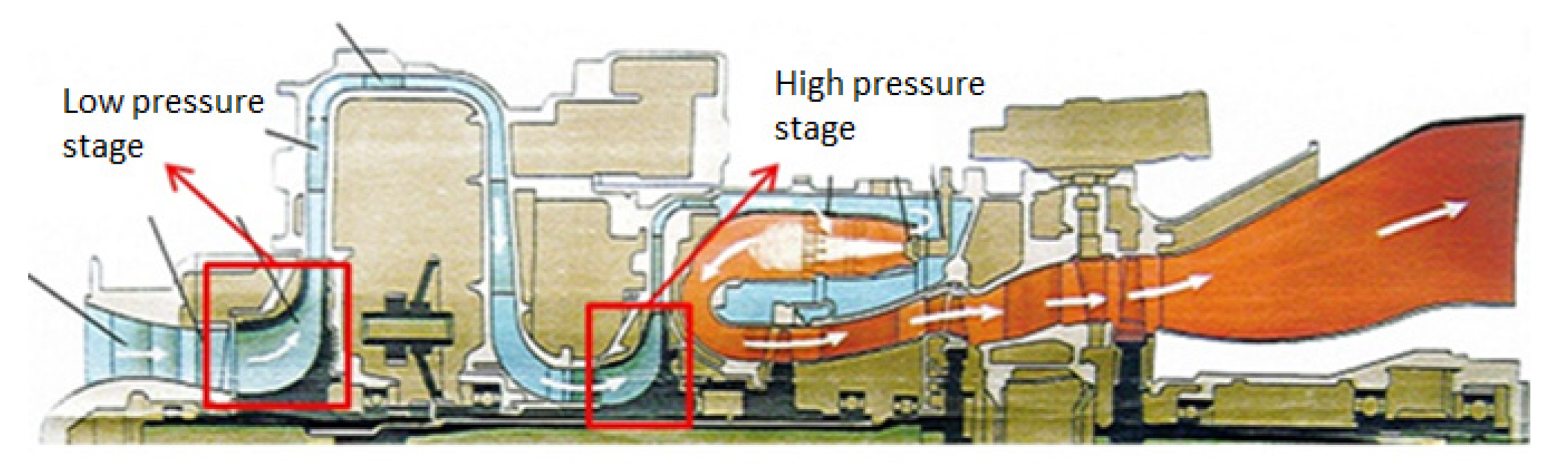
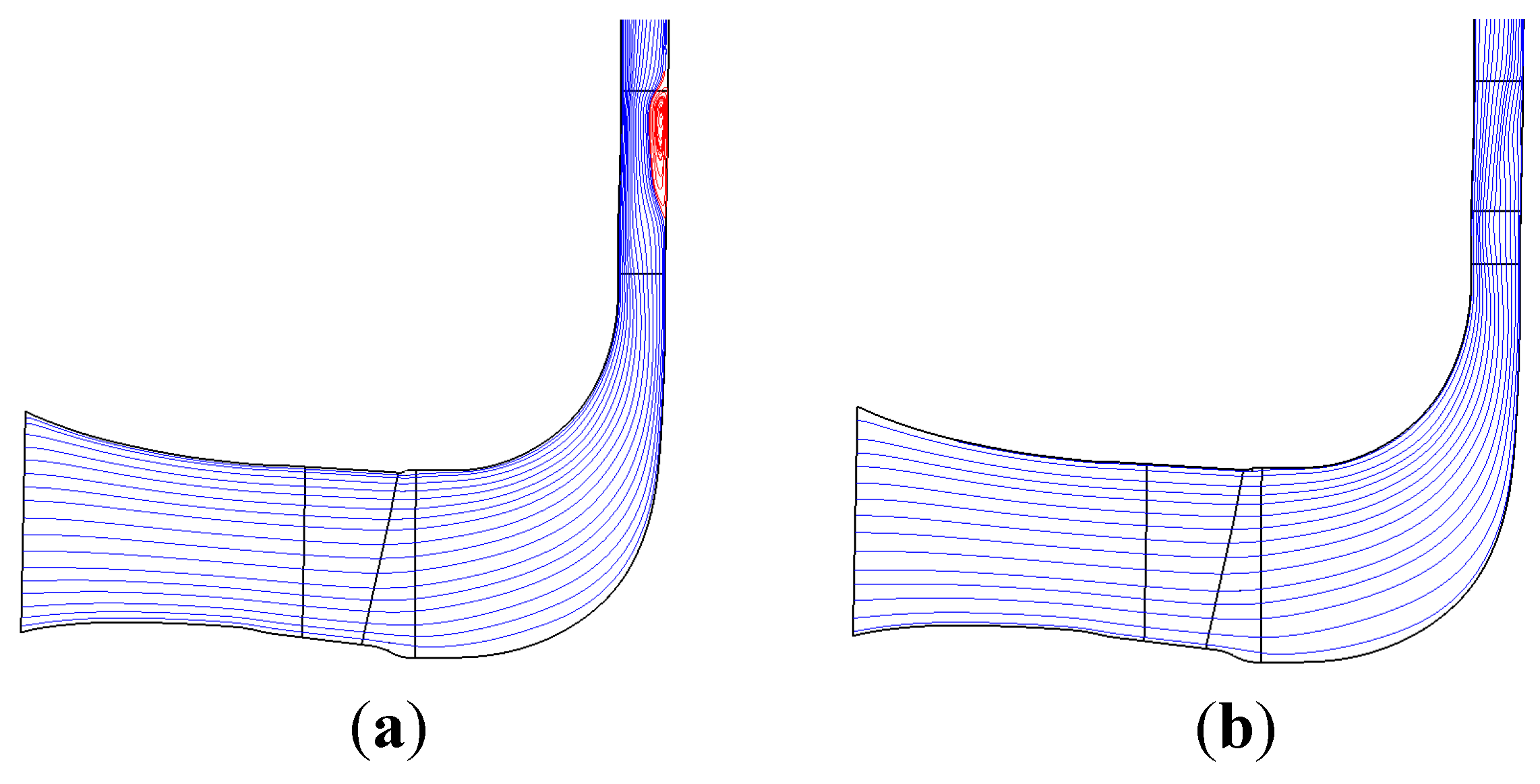
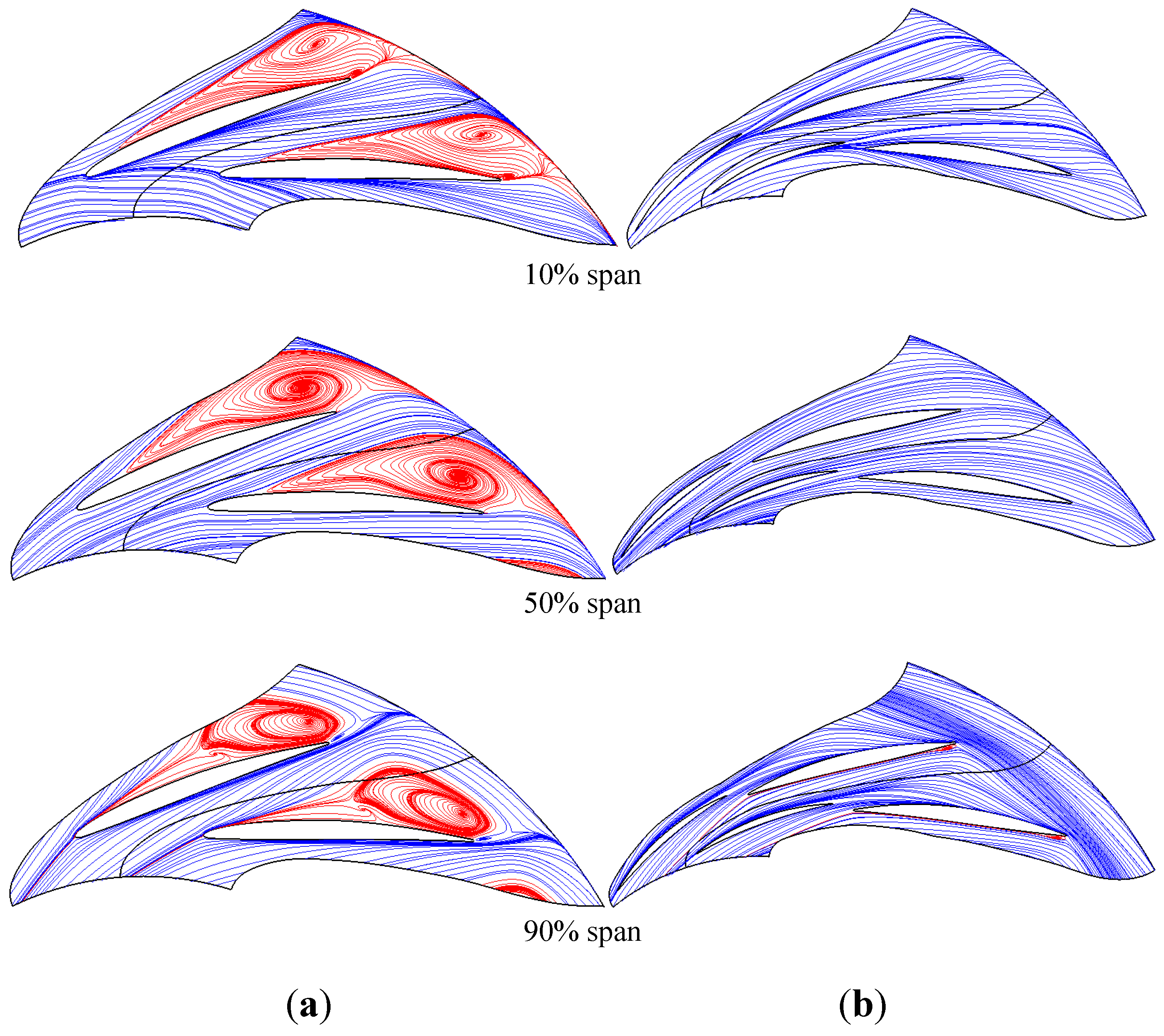
A low pressure stage centrifugal compressor in a MW level gas turbine is optimized by the 1D optimization method based on the iSIGHT software. The optimization results show that too large diameter ratio D3/D2 is the main cause of low efficiency. The Numeca results also show that there is a large vortex in the vaneless diffuser, which also validates the reliability of the 1D calculation results.
(3)
The vaned diffuser is redesigned according to the 1D optimization results and the matching of vaneless and vaned diffusers. The Numeca results show that the vortex in the vaneless diffuser disappears in optimization design. After optimization, the entire stage pressure ratio is increased by approximately 4%, and the efficiency is increased by approximately 2%.

Nomenclature

b
hub to shroud passage width
b *
ratio of vaneless diffuser inlet width to impeller exit width
B
aerodynamic blockage
c f
skin friction coefficient
C
absolute velocity
C p
specific heat at constant pressure
C m
absolute meridional velocity
C θ
absolute tangential velocity
d
diameter
d H B
hydraulic diameter
D f
diffusion factor
Δ h t h
euler work
L B
impeller flow length
L Z
axial length of impeller
m ˙
mass flow rate
U
Impeller periphery velocity
W
relative velocity
Z
number of blade
α
absolute flow angle
β
relative angle
ϕ
flow coefficient
γ
meridional inclination angle
η
Efficiency
ε
wake fraction of blade-to-blade space
μ
slip factor, μ = C θ 2 C θ 2
ρ
density
σ
slip factor, σ = 1 C s l i p U 2

Subscripts

1
impeller inlet condition
2
impeller outlet condition
3
vaneless diffuser outlet condition
4
vaned diffuser outlet condition
m
meriditional direction
θ
tangential direction
h
hub
s
shroud

Acknowledgments

This work is supported by the National Natural Science Foundation of China (Grant No. 51276093).

Author Contributions

All authors have contributed to writing and revisions of this manuscript.

Conflicts of Interest

The authors declare no conflict of interest.

References

  1. Galvas, M.R. Fortran Program for Predicting Off-Design Performance of Centrifugal Compressors; TN D-7487; Technical Report for National Aeronautics and Space Administration (NASA): Cleveland, OH, USA, 1973. [Google Scholar]
  2. Aungier, R.H. Mean streamline aerodynamic performance analysis of centrifugal compressors. J. Turbomach. 1995, 117, 360–366. [Google Scholar] [CrossRef]
  3. Oh, H.W.; Yoon, E.S.; Chung, M.K. An optimum set of loss models for performance prediction of centrifugal compressors. Proc. Inst. Mech. Eng. Part A J. Power Energy 1997, 211, 331–338. [Google Scholar] [CrossRef]
  4. Japikse, D. Centrifugal Compressor Design and Performance, 3rd ed.; Concepts ETI Inc.: Wilder, TN, USA, 1996; pp. 2.26–2.81. [Google Scholar]
  5. Mengistu, T.; Ghaly, W.; Mansour, T. Aerodynamic shape optimization of turbine blades using a designparameter-based shape representation. Proc. ASME Turbo Expo 2007 Power Land Sea Air 2007, 6, 1395–1404. [Google Scholar]
  6. Rossetti, G.; Ardizzon, G.; Pavesi, G. An optimum design procedure for an aerodynamic radial diffuser with incompressible flow at different reynolds numbers. J. Power Energy 2014, 224, 69–84. [Google Scholar] [CrossRef]
  7. Klassen, H.A.; Wood, J.R. Experimental Performance of a 16.1 Centimetre Tip Diameter Centrifugal Compressor Designed for a 6:1 Pressure Ratio; National Aeronautics and Space Administration (NASA): Cleveland, OH, USA, 1979. [Google Scholar]
  8. Tamaki, H.; Nakao, H.; Saito, M. The experimental study of matching between centrifugal compressor impeller and diffuser. J. Turbomach. 1999, 121, 113–118. [Google Scholar] [CrossRef]
  9. Caser, M. The matching of a vaned diffuser with a radial compressor impeller and its effect on the stage performance. J. Turbomach. 2014, 136. [Google Scholar] [CrossRef]
  10. Cumpsty, N.A. Compressor Aerodynamics; Longman Group Ltd.: Harlow, Essex, UK, 1989. [Google Scholar]
  11. Conrad, O.; Raif, K.; Wessels, M. The calculation of performance maps for centrifugal compressors with vane-island diffusers. In Proceedings of the ASME Twenty-fifth Annual International Gas Turbine Conference and Twenty Second Annual Fluids Engineering Conference on Performance Prediction of Centrifugal Pumps and Compressors, New Orleans, LA, USA, 9–13 March 1980; pp. 135–147.
  12. Jansen, W. A Method for Calculating the Flow in a Centrifugal Impeller When Entropy Gradients Are Present; Royal Society Conference on Internal Aerodynamics (Turbomachinery): London, UK, 1967; pp. 133–146. [Google Scholar]
  13. Coppage, J.E.; Dallenbach, F.; Eichenberger, H.P. Study of Super-Sonic Radial Compressors for Refrigeration and Pressurization Systems; Technical Report for Wright Air Development Center (WADC): Los Angeles, CA, USA, 1956. [Google Scholar]
  14. Daily, J.W.; Nece, R.E. Chamber dimension effects on induced flow and frictional resistance of enclosed rotating disks. Trans. ASME J. Basic. Eng. Power 1966, 88, 49–62. [Google Scholar] [CrossRef]
  15. Rodgers, C. Influence of Impeller and Diffuser Characteristics and Matching on Radial Compressor Performance; Technical Paper for Society of Automotive Engineers: Warrendale, PA, USA, 1 January 1961. [Google Scholar]
  16. Johnston, J.P.; Dean, R.C. Losses in vaneless diffusers of centrifugal compressors and pumps: Analysis, experiment, and design. J. Eng. Gas Turbines Power. 1966, 88, 49–62. [Google Scholar] [CrossRef]
  17. Stodola, A. Steam and Gas Turbines; McGraw-Hill: New York, NY, USA, 1945. [Google Scholar]
  18. Wiesner, F.J. A review of slip factors for centrifugal impellers. J. Eng. Power. 1967, 89, 558–572. [Google Scholar]
  19. Qiu, X.W.; Japikse, D.; Zhao, J.; Anderson, M.R. Analysis and validation of a unified slip factor model for impellers at design and off-design conditions. J. Turbomach. 2011, 133, 041018:1–041018:9. [Google Scholar] [CrossRef]
  20. Stanitz, J.D. One-Dimensional Compressible Flow in Vaneless Diffusers of Radial and Mixed-Flow Centrifugal Compressors, Including Effects of Friction, Heat Transfer and Area Change; Technical Report for Lewis Flight Propulsion Laboratory: Cleveland, OH, USA, January 1952. [Google Scholar]
  21. Aungier, R.H. Aerodynamic performance analysis of vaned diffusers. Fluid Mach. Compon. 1990, 110, 37–44. [Google Scholar]
  22. Doostmohammadi, A.A.; Hajilouy-Benisi, A.; Mojaddam, M. Experimental and numerical investigation of losses in centrifugal compressor components. In Proceeding of the ASME Turbo Expo 2013: Turbine Technical Conference and Exposition, San Antonio, TX, USA, 3–7 June 2013.
  23. Skoch, G.J.; Prahst, P.S.; Wernet, M.P. Laser Anemometer Measurements of the Flow Field in a 4:1 Pressure Ratio Centrifugal Impeller; Technical Report for National Aeronautics and Space Administration: Orlando, FL, USA, 1997. [Google Scholar]
  24. Kazuyuki, S. Aerodynamic Shape optimization and knowledge mining of centrifugal fans using simulated annealing coupled with a neural network. In Proceedings of the 32nd Design Automation Conference, Philadelphia, PA, USA, 10–13 September 2006; pp. 291–300.
  25. Sarhadi, A.; Tahani, M.; Kolahan, F.; Sarhadi, M. Multi-Objective optimal design of sandwich composite laminates using simulated annealing and FEM. In Proceeding of the ASME 2008 Pressure Vessels and Piping Conference, Chicago, IL, USA, 27–31 July 2008; pp. 597–606.

