Article

Slit Wall and Heat Transfer Effect on the Taylor Vortex Flow

1
School of Energy and Power Engineering, Jiangsu University, Zhenjiang 212013, China
2
Research Center of Fluid Machinery Engineering and Technology, Jiangsu University, Zhenjiang 212013, China
3
School of Mechanical and Aerospace Engineering, Gyeongsang National University, Jinju 660-701, Korea
*
Authors to whom correspondence should be addressed.
Energies 2015, 8(3), 1958-1974; https://doi.org/10.3390/en8031958
Submission received: 30 November 2014 / Revised: 3 February 2015 / Accepted: 3 March 2015 / Published: 12 March 2015

Abstract

:
The Taylor vortex flow in the plain model with a constant temperature gradient effect was studied by experimental measurement, and the preliminary features of Taylor vortex flow affected by heat transfer process were obtained. This flow field in the plain model was also studied by numerical simulation. The reliability of numerical simulation was verified by comparing the numerical results with the experimental ones. To study the slit wall effect on this flow regime under the same temperature gradient conditions, another three models with different slit numbers (6, 9 and 12) were considered. The vortex pairs were found to have a motion along the axial direction. Because of the existence of the temperature gradient, the axial flow in the annulus gap was enhanced, but the radial velocity near the inner cylinder was found to be weakened. The heat flux generated by the inner cylinder was also compared among different models, and it was found that the heat flux generated by the 6-slit model was increased by 4.5% compared to that of the plain model, and the 12-slit model generated the maximum heat flux, which has the best heat transfer ability.

1. Introduction

The flow between two concentric cylinders with the inner one rotating or both rotating, called Taylor-Couette flow, was first studied by Taylor [1]. Since then, many researchers have studied the instability causing Taylor vortices. This kind of flow can be found in the electric motor, clutch, and the transmission system of numerical control (NC) machines [2]. Further study of the Taylor-Couette flow in the above devices is helpful for improving the performance and long term stable operation of these machines. As the rotor rotates in the motor, the heat generated by the rotor not only affects the performance of the motor, but also decreases the service life of the motor. During operation of the NC machine, the main shaft with high rotation speed generates a large heat flux, which reduces the fabrication precision of the machine. Study of the fluid dynamic and heat transfer phenomenon in the concentric cylinders is essential for solving the problem mentioned above.
Lepiller et al. [3] studied the effects of a weak temperature gradient on the stability of the circular Couette flow, and found the existence of a weak temperature gradient destabilized the Couette flow, and a pattern of travelling helicoidal vortices was found near the bottom of the system. Poncet et al. [4] applied a Reynolds stress model to study heated Taylor-Couette flow with an axial Poiseuille flow, and provided the correlations for the averaged Nusselt numbers along both cylinders according to the flow control parameters Re (Reynolds number) and Pr (Prandtl number). Kang et al. [5] studied the temperature gradient effect on the circular-Couette flow, and found the vortex size increased as the Richardson number increased.
The above studies were performed under plain wall conditions. That is, the annulus surface was a smooth plane. However, in engineering applications the walls of the outer cylinders generally have complex geometries. Therefore, studies of a Taylor-Couette flow considering the effect of the cylinder wall geometry are necessary. Hayase [6] studied the heat transfer between rotating coaxial cylinders with periodically embedded cavities, and found the flow in a cavity interacted with Taylor vortices in the annular space to enhance the heat transfer. Lee and Minkowycz [7] studied the heat transfer characteristics using a naphthalene sublimation technique in the annular gap between two short concentric cylinders with different wall geometries, and they obtained qualitative information regarding heat transfer, but did not address the flow phenomena inside the annular gap. Liu et al. [8,9] studied the slit wall and temperature gradient effect on the flow transition process in Taylor-Couette flow, and found the transition process in the models with a larger number of slits (9-, 18-slit models) was accelerated due to the slit wall.
As found in the previous studies, the slit wall has an obvious effect on the flow instability, but there is little work about the slit wall effect on the stability of Taylor vortex flow, and there are no studies on the slit number effect on the heat transfer process. Only the velocity distribution of limited area can be obtained by particle image velocimetry(PIV) experimental measurements, and in addition, the temperature distribution and its effect to the flow structure in the gap are hard to obtain by experimental methods. Based on the investigation of the slit wall effect on Taylor vortex flow and wavy vortex flow [10,11], we studied a constant temperature gradient and slit number effect on Taylor vortex flow, which was rarely studied by numerical simulation, by PIV (TSI INCORPORATED, Shoreview, MN, USA) measurements and numerical simulation. By comparing the results of four different models, the characteristics of the vortex flow in the annulus gap and the slit number effect on the heat transfer process were obtained.

2. Experimental Apparatus and Results

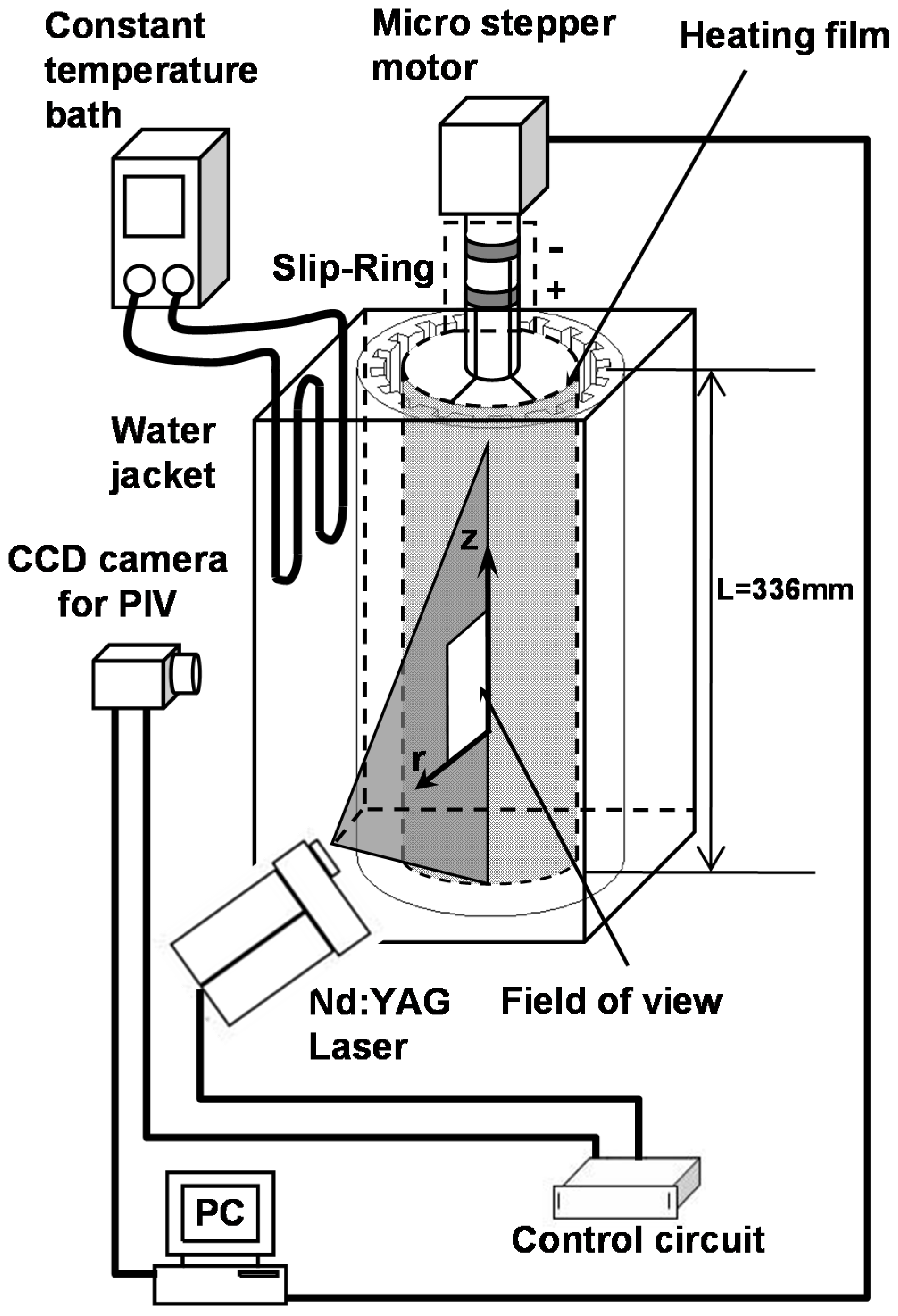
2.1. Experimental Apparatus

Figure 1 shows the experimental apparatus and set-up used to measure the velocity field. The inner cylinder was made of aluminum pipe which has an external radius ri = 33 mm and a black coating to prevent the reflection of a laser. The outer cylinder was made of acrylate and had an inner radius ro = 40 mm. The annulus gap (d) between the cylinders was 7 mm and the length of the cylinders (L) was 336 mm. The radius ratio (ri/ro) and aspect ratio (L/d) were 0.825 and 48, respectively, following the studies of Cole [12] and Wereley and Lueptow [13]. The geometry of the experimental models are shown in Figure 2, the 9-slit model has nine slits in the outer cylinder, and the depth and width of each slit is 5 mm. This micro-stepper motor was controlled through a computer, which allowed for the precise control of angular velocity (Ω) and the acceleration to the preset velocity. The outer cylinder was kept stationary. The working fluid sodium iodide solution filled the annular gaps and the space between the outer cylinder and the enclosure box in order to avoid the light refraction effect. More details of this method can be found in the previous study by Lee [14].
Figure 1. Schematic diagram of the experimental apparatus.
Energies 08 01958 g001
Figure 2. Geometries of models: (a) Plain model; and (b) 9-Slit model.
Energies 08 01958 g002
During the experiment, the temperature of the inner and outer cylinders was carefully controlled to keep the imposed temperature gradients constant. The details were explained in a previous study by Liu [8]. The temperature was measured by thermocouples along the surface of inner and outer cylinders. Each cylinder was installed five thermocouples. The average temperature of outer cylinder surface was Tout = 24.0 °C, the average surface temperature of the inner cylinder was Tin = 25.2 °C. And ΔT is the temperature increments across the gap, defined as ΔT = (TinTout). In this paper, ΔT equals 1.2 °C. The effect of the temperature gradient is parameterized by the Grashof number, which is defined as G r = d 3 β g Δ T / v 2 g , where g is the acceleration due to gravity, the thermal expansion coefficient β is 0.00057 1/k. The kinematic viscosity ν is 1.52 cSt, the density of the working fluid is 1780 kg/m3, the specific heat capacity and the thermal conductivity of the working fluid is 2725 J/kg k, 0.209 w/m k respectively, so the Grashof number considered in this study was 1000 and Pr number was 35.6.
In this experiment, the rotational speed was expressed as a Reynolds number, which is defined as Re = ridΩ/ν. From the experimental results of Lee [14], when the Reynolds number is within the range of 103 to 124, Taylor vortex flow will appears in plain model. In this paper, the rotation angular velocity of inner cylinder is fixed to 0.7238 rad/s, and the Reynolds number is 110.

2.2. Experimental Results

Figure 3 shows the instantaneous flow fields on the radial-axial plane at Re = 110. Each figure has the same time interval of 1 s, and the figures are labeled T1, T2, T3, and T4. The axial position, Z* = z/d, and the radial position, R* = (rri)/d, were normalized by the annulus gap width. Compared with the Taylor vortex flow, the Taylor vortices affected the heat transfer process had motion along the axial direction, which is named helical vortex flow [8]. From the Figure 3, the counterclockwise rotation vortex was found to be slightly larger than the clockwise rotation one, and the vortex pairs had motion along the axial direction. By comparing this results with that seen under isothermal conditions, it was found the Taylor vortex flow appears at this Re number and the vortices in the annulus gap had the same size, which rotated around a fixed center located in the middle of the annulus gap. Because of the higher temperature of the rotating inner cylinder and lower temperature of the outer cylinder, the buoyancy force generated an upward flow motion near the inner cylinder and a downward flow motion near the outer cylinder, this motion enhanced the clockwise rotation vortices and drove the vortex pairs to moves in an upward direction. Figure 3b shows this flow regime in 9-slit model, compared with the result of plain model, it was found the vortices in the slit model were larger than that of plain model because of the flow in the annulus gap expanded into the slit space.
Figure 3. Instantaneous velocity fields of helical vortex flow: (a) Plain model; and (b) 9-slit model. The scale of the vector is 0.002 m/s. * means the center of the vortex.
Energies 08 01958 g003
Because of the limitations of the experimental method, a numerical simulation was adopted to research the characteristics of the vortex flow in the annulus gap in different models, and to study the slit wall effect on the heat transfer process.

3. Numerical Calculation Method

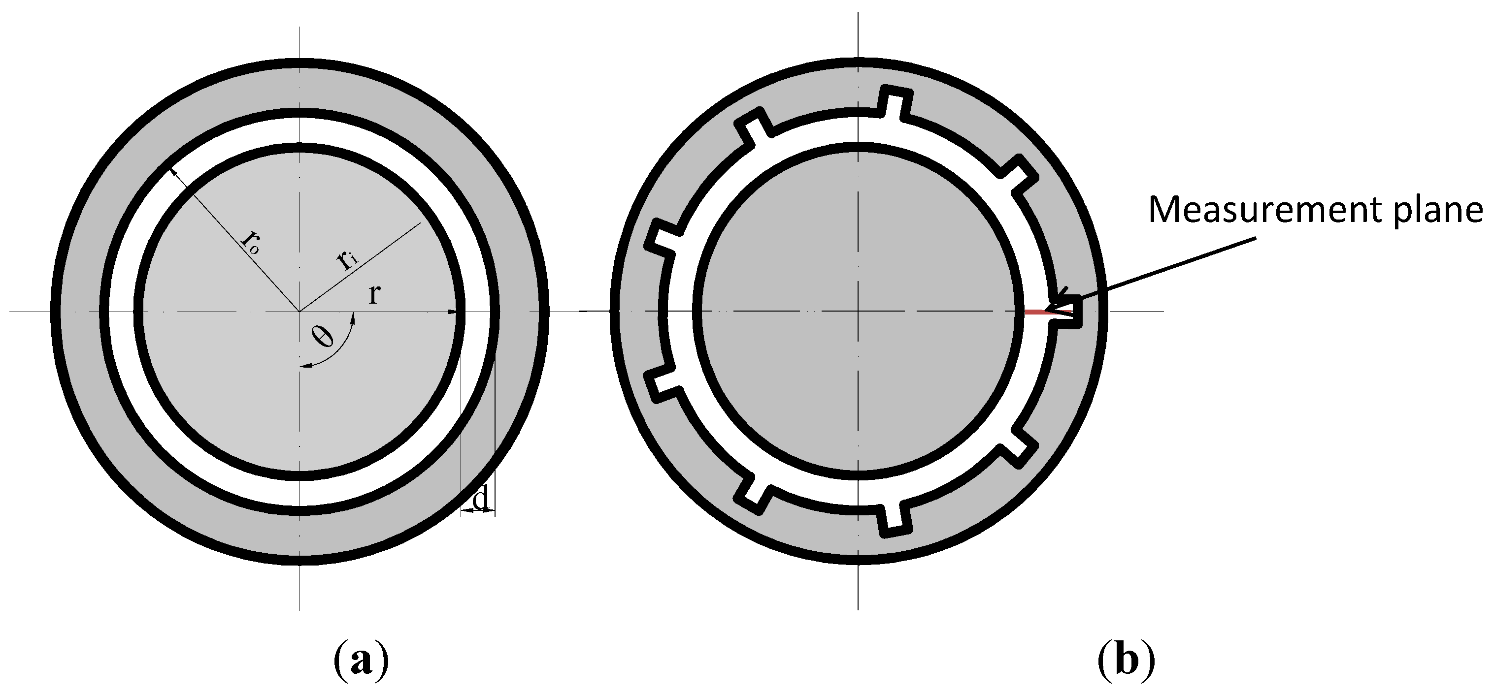
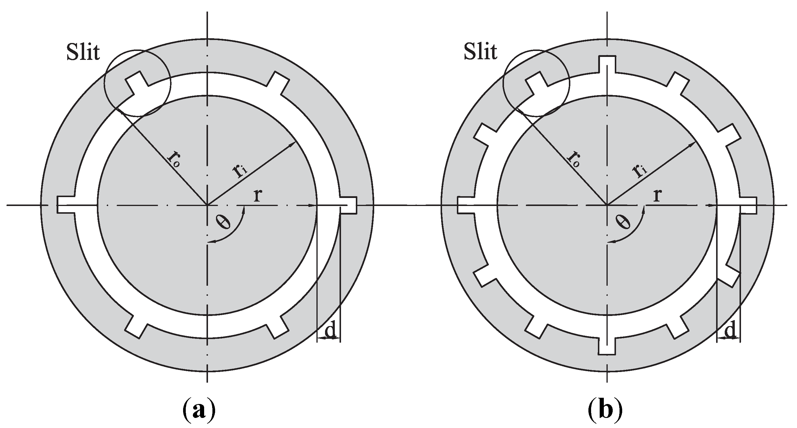
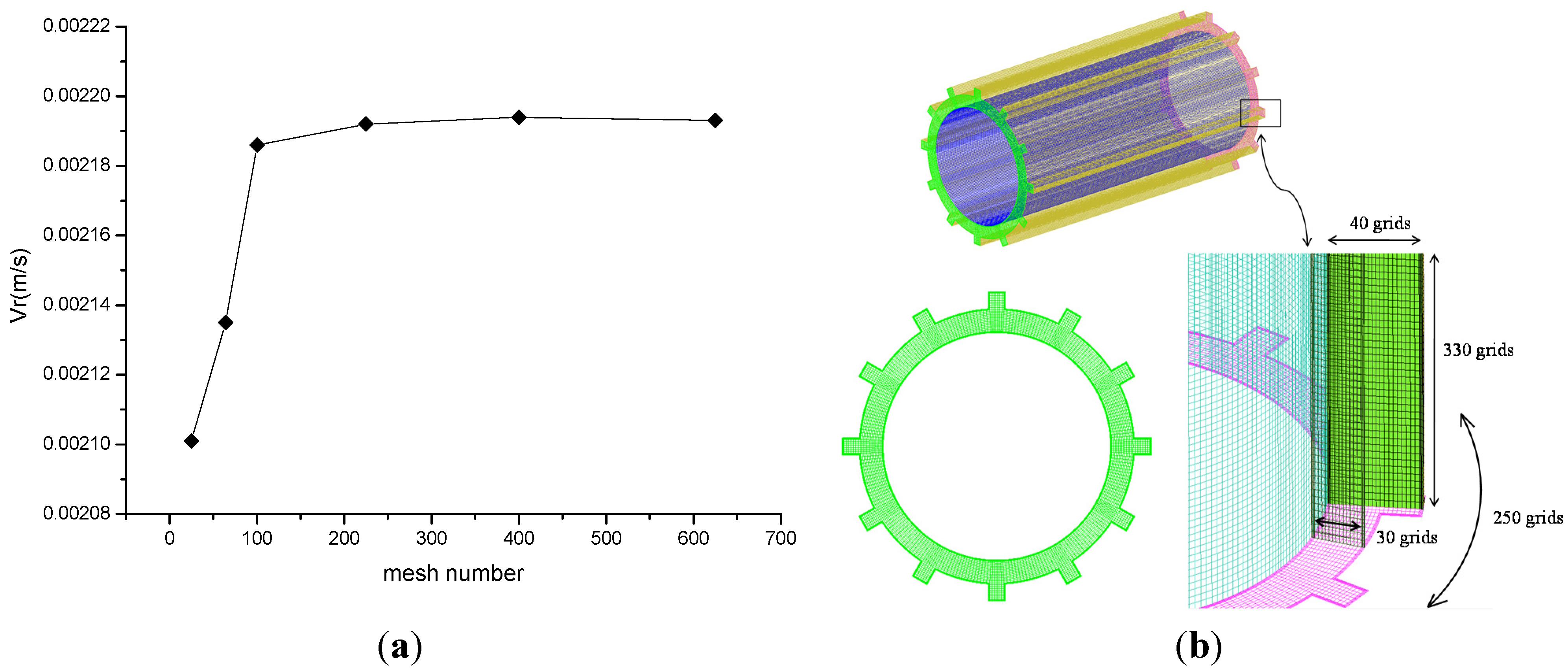
3.1. Calculation Model
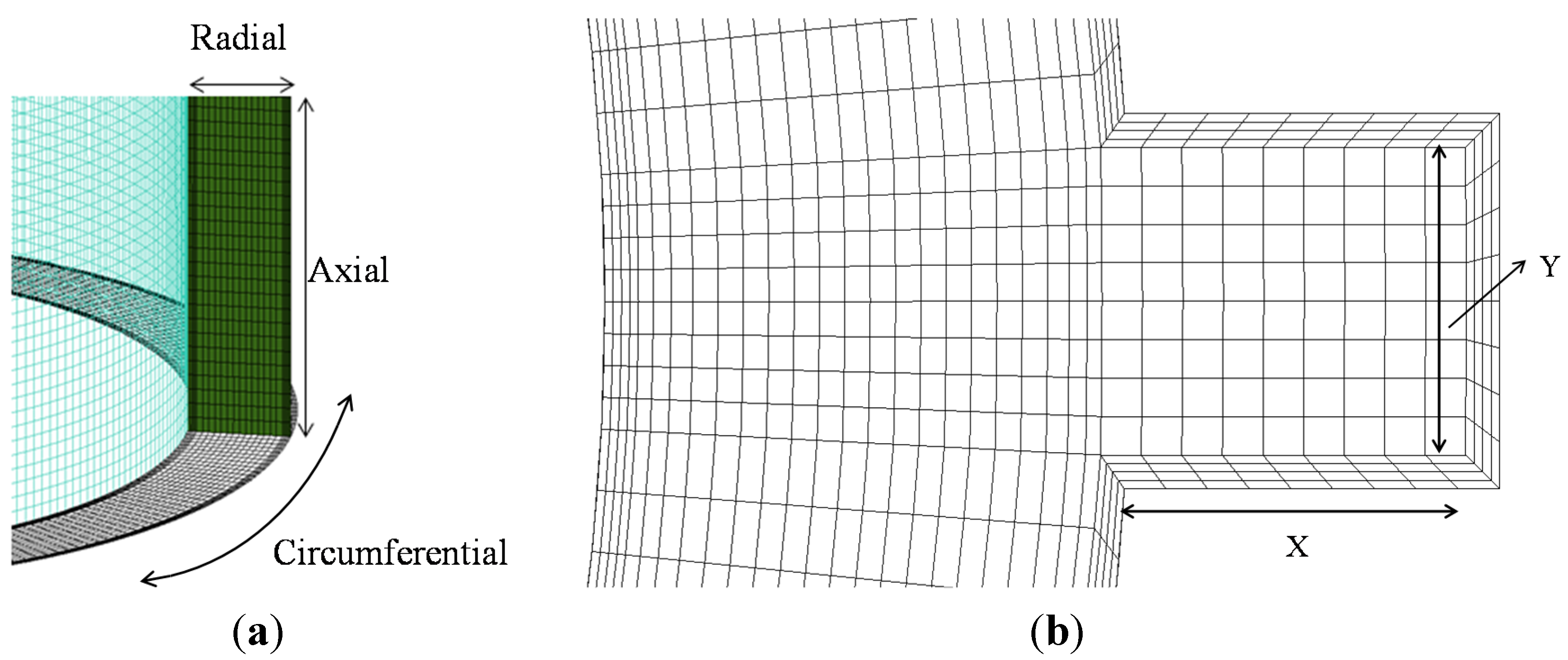
Four different models were considered in this numerical simulation work, the plain and 9-slit models are the same as those used in the experimental work, and another two models with different slit numbers were also considered, as shown in Figure 4, these slit numbers are 6 and 12, respectively. The radius of the inner and outer cylinder, annulus width and length is consistent with the plain model, the width and depth of each slit is the same as in the 9-slit model.
Figure 4. Geometries of calculation models: (a) 6-slit model; (b) 12-slit model.
Energies 08 01958 g004

3.2. Numerical Mode

Structured mesh was applied in this study which is more computationally efficient and also convenient for the present domain, and the mesh of 12-slit model is shown in Figure 5. In order to obtain an accurate calculation result, the local mesh refinement method was adopted near the wall. A mesh independence study was conducted to verify the effect of density on the final simulation results. A structured hexahedral mesh was selected. Figure 5 shows a brief illustration of the grid employed in the present study.
Figure 5. Brief scheme of the mesh construction; (a) Plain model; and (b) Slit wall region.
Energies 08 01958 g005
In order to set a criterion to judge the grid independence, the vortex pair number and maximum radial velocity was compared with experimental results in different schemes. The first step was to keep the grid numbers along the circumferential and axial directions fixed, which is 250 and 330 respectively, the radial grid number was 10, 15, 20, 30, 40 and 50. The simulation results are shown in Figure 6a, where there was nearly no change in the maximum radial velocity if the radial grid number was larger than 30. The number of Taylor vortex pairs was 24 when the radial grid number was smaller than 30, and when the radial grid number larger than 30, this number was 26, which was the same as in the experimental results. To minimize the computational time cost, the radial grid of 30 was the best choice for all the cases.
Figure 6. Simulation results with different grid number. (a) Different radial grid number; and (b) Different circumferential and axial grid number.
Energies 08 01958 g006
As discussed above, the radial grid number was kept as 30. The second step was to keep the axial grid number fixed as 330, while the circumferential grid number was 120, 160, 200, 250, 300 and 350. The simulation results are shown in Figure 6b, where there was nearly no change in the maximum radial velocity when the circumferential grid number was larger than 250. The number of Taylor vortex pairs was not changed with circumferential grid density. Therefore, for the same computational cost reasons, the circumferential grid number was set as 250.
For the plain model, the final step was to determine the appropriate value for the number of the axial grids, which were 160, 200, 240, 330, 400 and 500. The simulation results are given in Figure 6b, where there was nearly no change in the maximum radial velocity when the axial grid number was larger than 330. The number of Taylor vortex pairs also did not change with axial grid density. Therefore, the axial grid number was set as 330. Finally, it was observed that a structured mesh with 250 × 30 × 330 grid points (along the circumferential, radial, and axial directions) was enough to provide the mesh independent results. The total mesh number was 2,475,000.
For the slit model, the grid scheme in the annulus gap was the same as in the plain model, and in the slit region, six different grid schemes were applied to study the grid independence along the x and y directions, which was 5 × 5, 8 × 8, 10 × 10, 15 × 15, 20 × 20, 25 × 25. When the grid number was larger than 10, there was nearly no change on the maximum radial velocity. The mesh of the 12-slit model is shown in Figure 7.
The commercial computational fluid dynamics (CFD) software FLUENT 13 (ANSYS Inc, Canonsburg, PA, USA) was used to solve the laminar flow. The solver is pressure-based and transient. The viscous model is laminar. The material of fluid is sodium iodide solution, which is used in experimental work. The problem considered in this paper was a combined natural- and forced-convection problem, since the Grashof number Gr (~1000) and Reynolds number Re (~110) were both non-negligible. We have not isolated their effects and investigated their relative contributions to the overall heat transfer, and we only considered them together, and the Boussinesq assumption is adopted to consider the natural convection effect. Under-relaxation factors are 0.3 for pressure, 0.7 for momentum, and 0.9 for energy. The discretization mode is second order for pressure, SIMPLEC for pressure-velocity coupling, second order upwind for momentum, and second order upwind for energy. The solution is computed from the inner cylinder, and all initial values are zero unless specified. All the convergence criteria are 0.0001. The outer cylinder with the surface temperature 24 °C is resting, and the inner cylinder with a surface temperature of 25.2 °C is rotating at the speed of 0.7238 rad/s, while stationary wall conditions are adopted at the ends of the model, the Gr and Pr numbers are the same as those in the experimental work. The characteristics of the vortex flow are described by the convergent calculation results.
Figure 7. Grid independence study of slit model. (a) Simulation results with different grid number; and (b) Grid in 12 slit model.
Energies 08 01958 g007

4. Analysis of Simulation Results

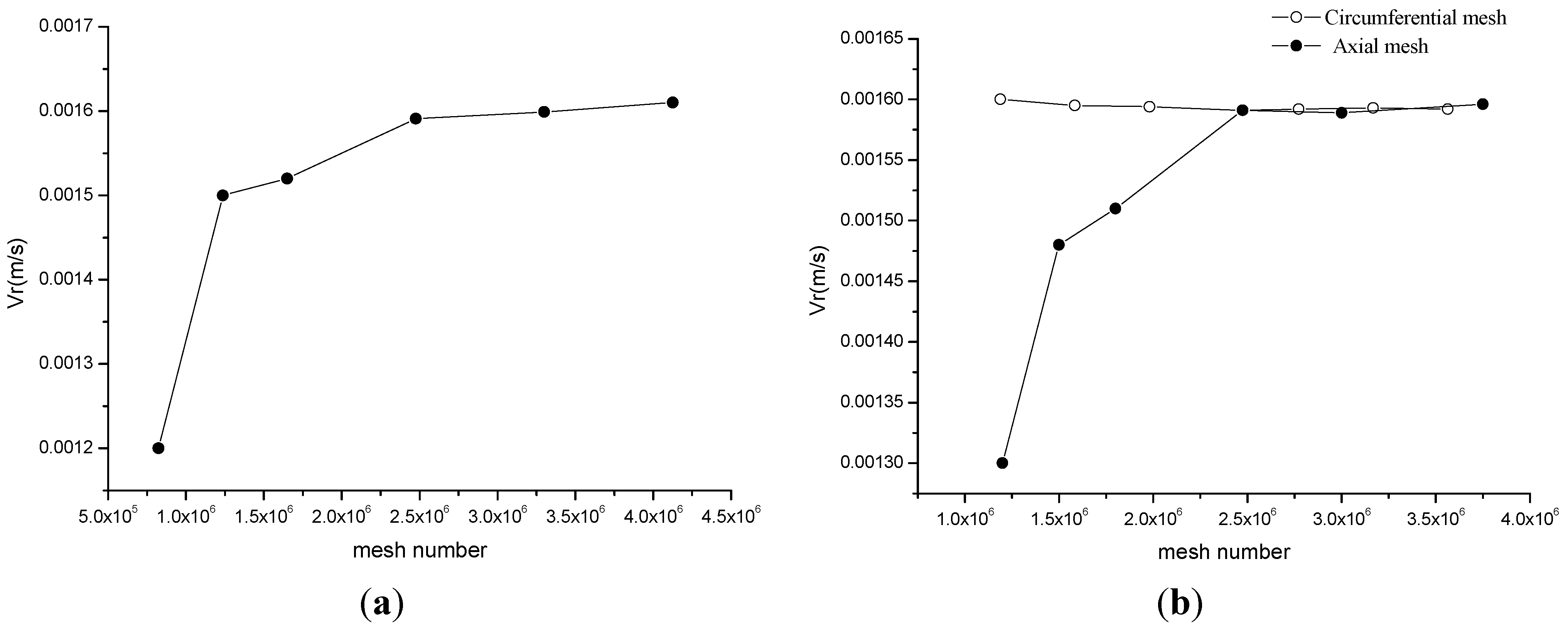
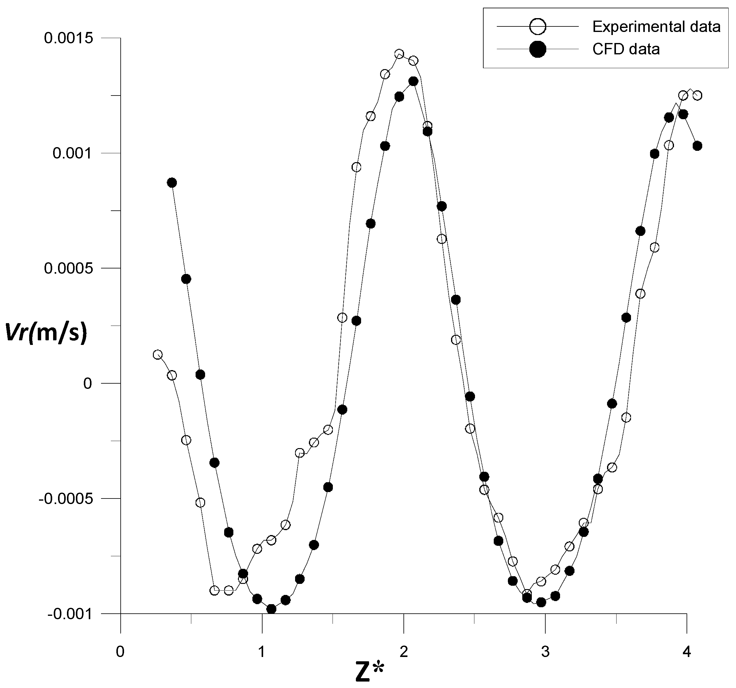
4.1. Numerical Validity

Figure 8 shows the velocity field in radial-axial plane of plain model, which was obtained by numerical simulation at Re = 110. The time interval between each result is 1 s, which is the same as in the experimental results. Comparing the velocity field of Figure 8 with Figure 3, it was found that the flow fields of helical vortex flow obtained from calculation and experiment were consistent.
Based on the movement of the vortex center, the axial motion velocity of this helical vortex flow was calculated, which was 1.5 mm/s. In order to further verify the accuracy of the numerical calculation, the radial velocity distribution at location R* = 0.5 was extracted from the numerical simulation and experimental results, which is shown in Figure 9. It is evident that the difference of radial velocity distributions obtained by numerical calculation and experiment is very small, except for the fact the maximum radial velocity of the experimental data is larger than that of CFD result. The reason for this divergence is as follows: the helical vortex flow is an unsteady flow, and the minimum interval time between each experimental datapoint is 0.2 s, and the time step size of CFD is 0.05 s, furthermore, the initial time of CFD and experimental data cannot be exactly the same, and it is difficult to get the CFD and experimental measurement results at the same time; and the other reason is that the average temperature near the inner and outer cylinder was used in the CFD work, but the real conditions in the experiment is that the temperature distribution cannot be uniform near both cylinder surfaces. Nevertheless, the flow regime and the vortex size in both the experimental and CFD results were the same, and during the CFD calculation we supposed the temperature gradient in all the models is uniform, so we think the numerical simulation method used in this paper is reliable for finding the slit number effect on the heat transfer process.
Figure 8. Instantaneous velocity fields of numerical simulation.
Energies 08 01958 g008
Figure 9. Radial velocity profile of PIV and CFD.
Energies 08 01958 g009

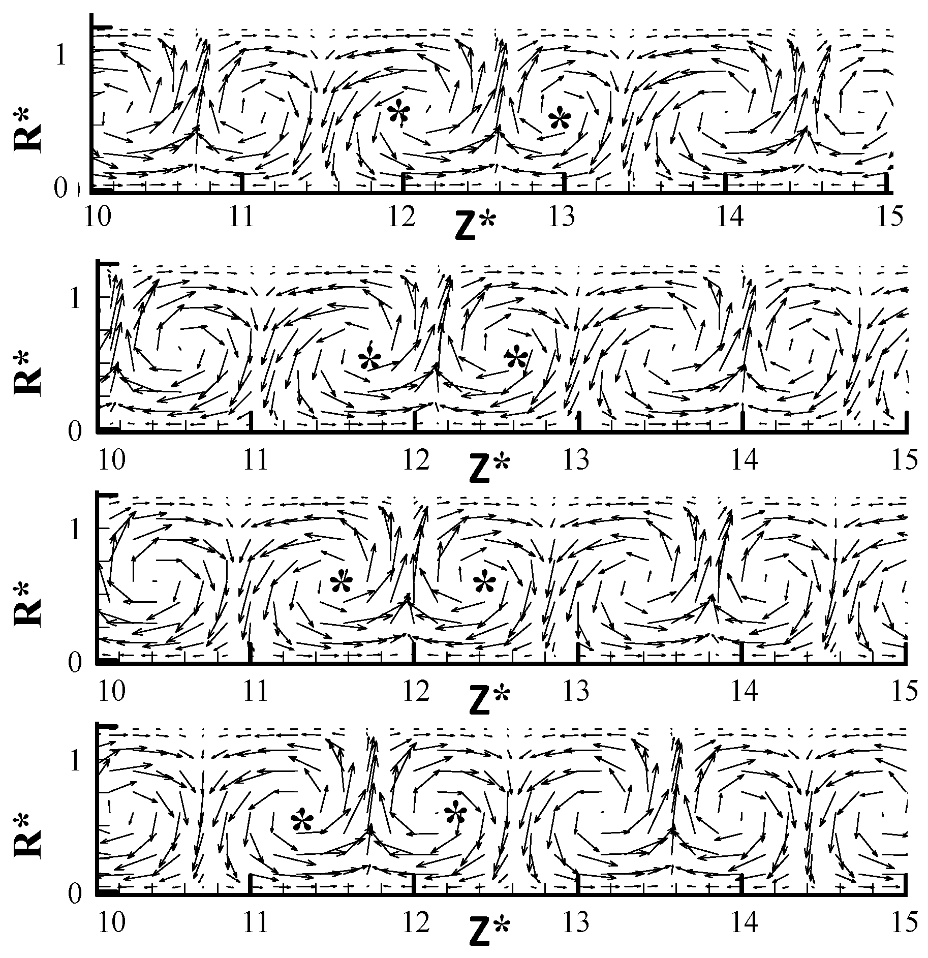
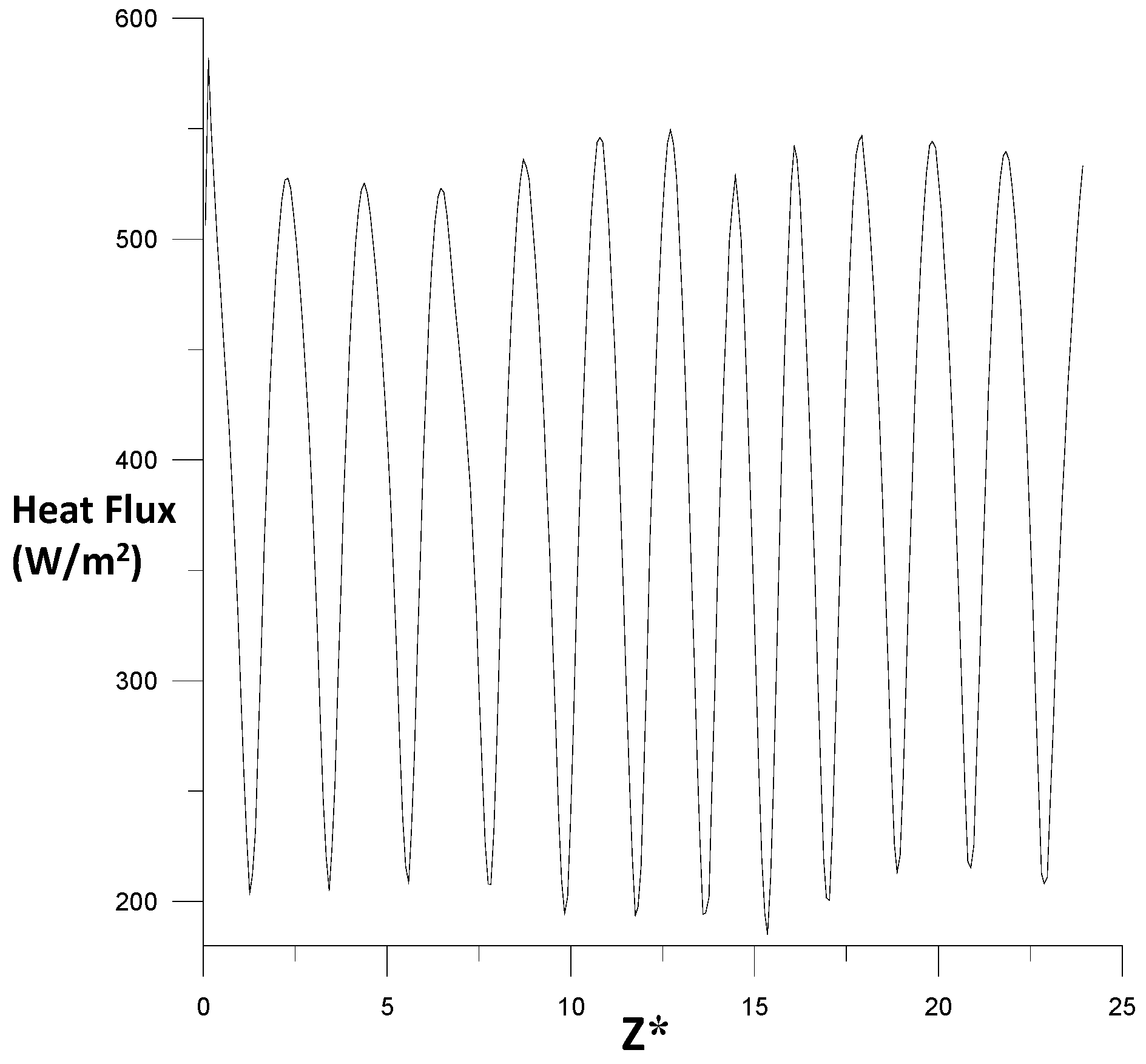
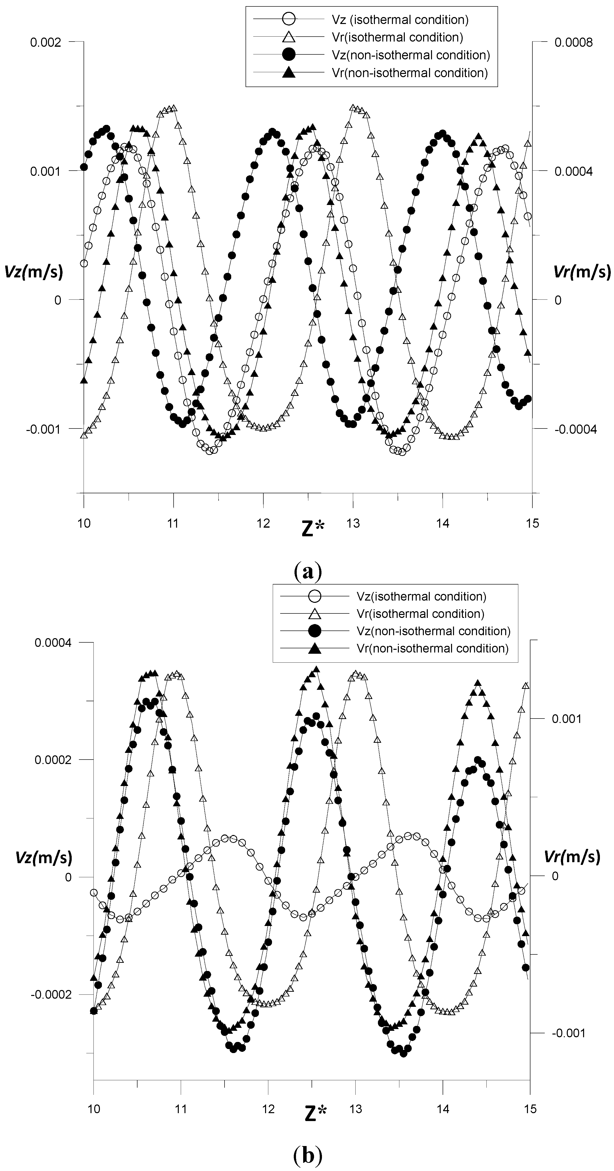
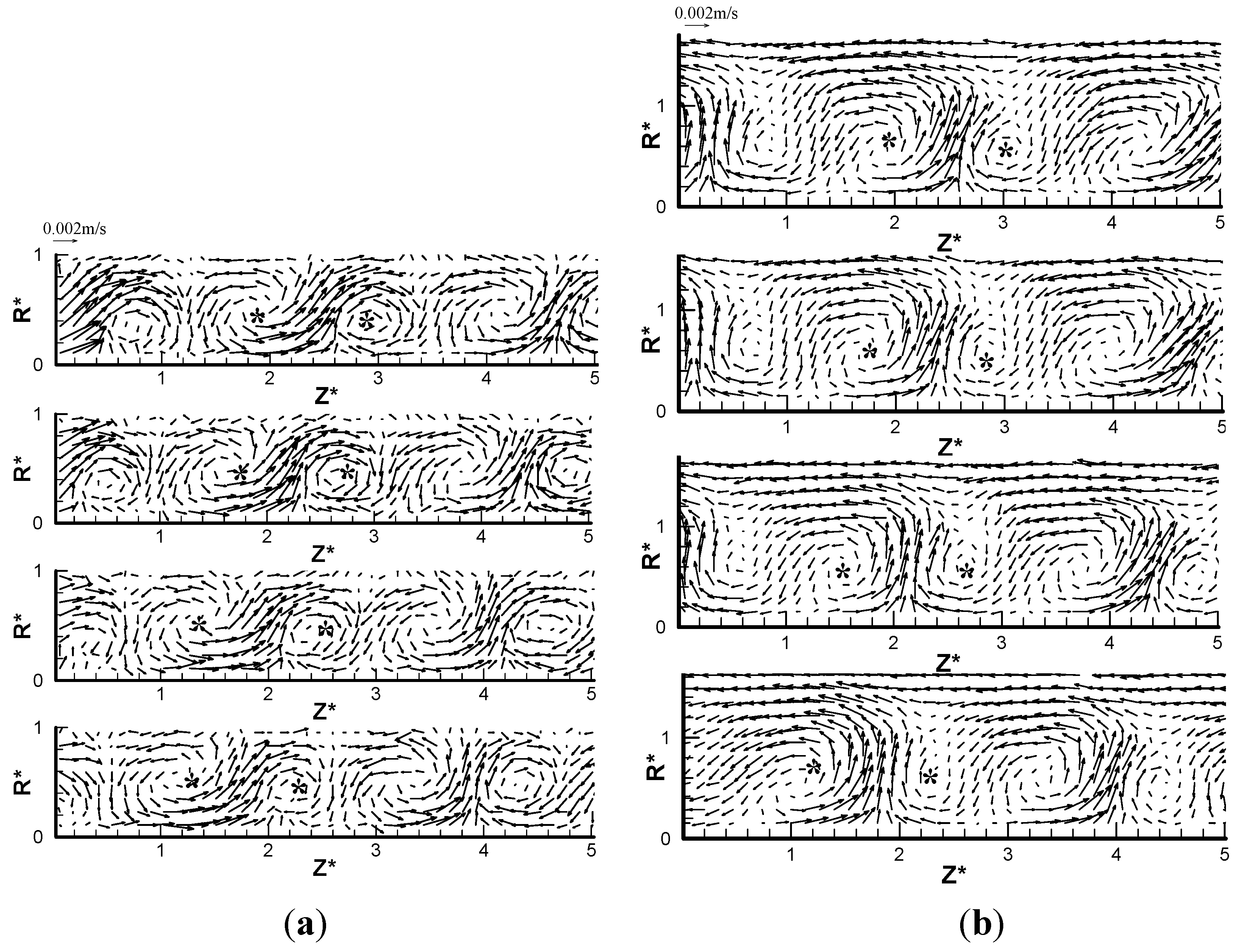
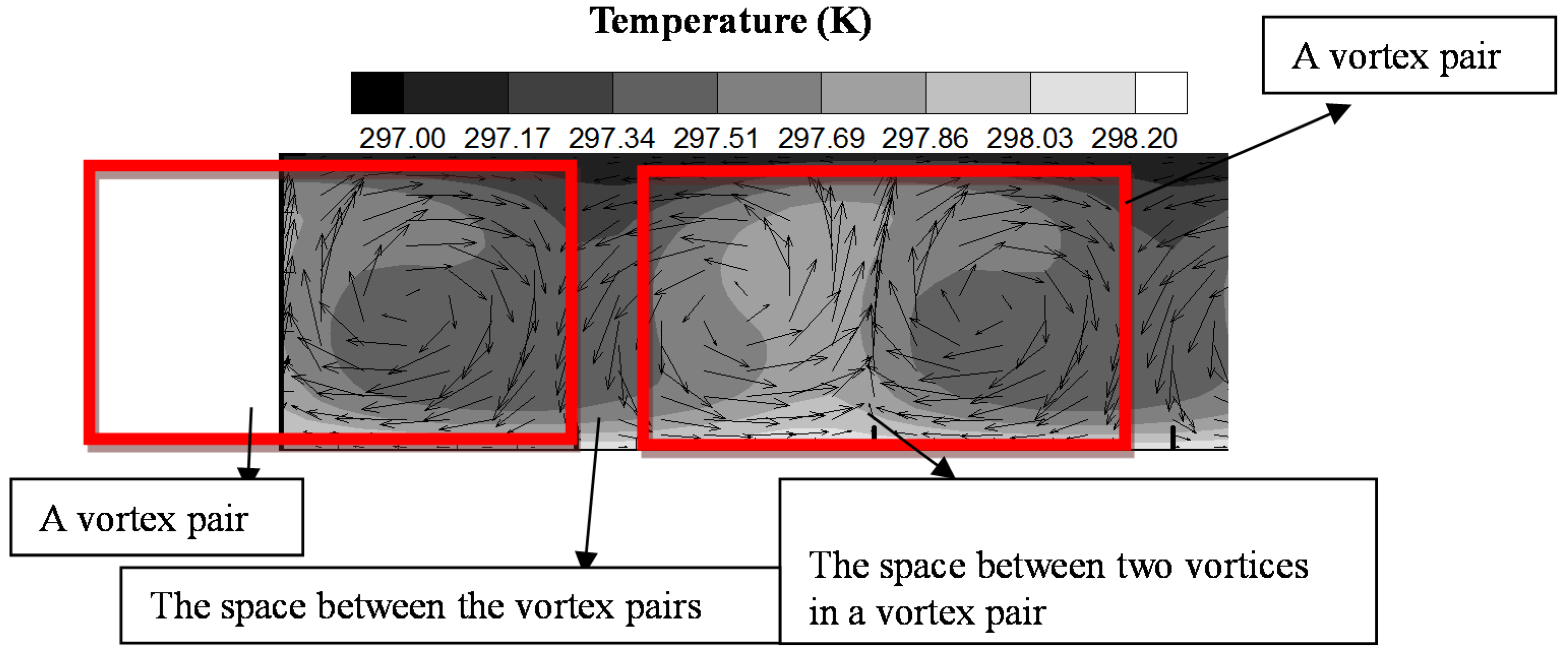
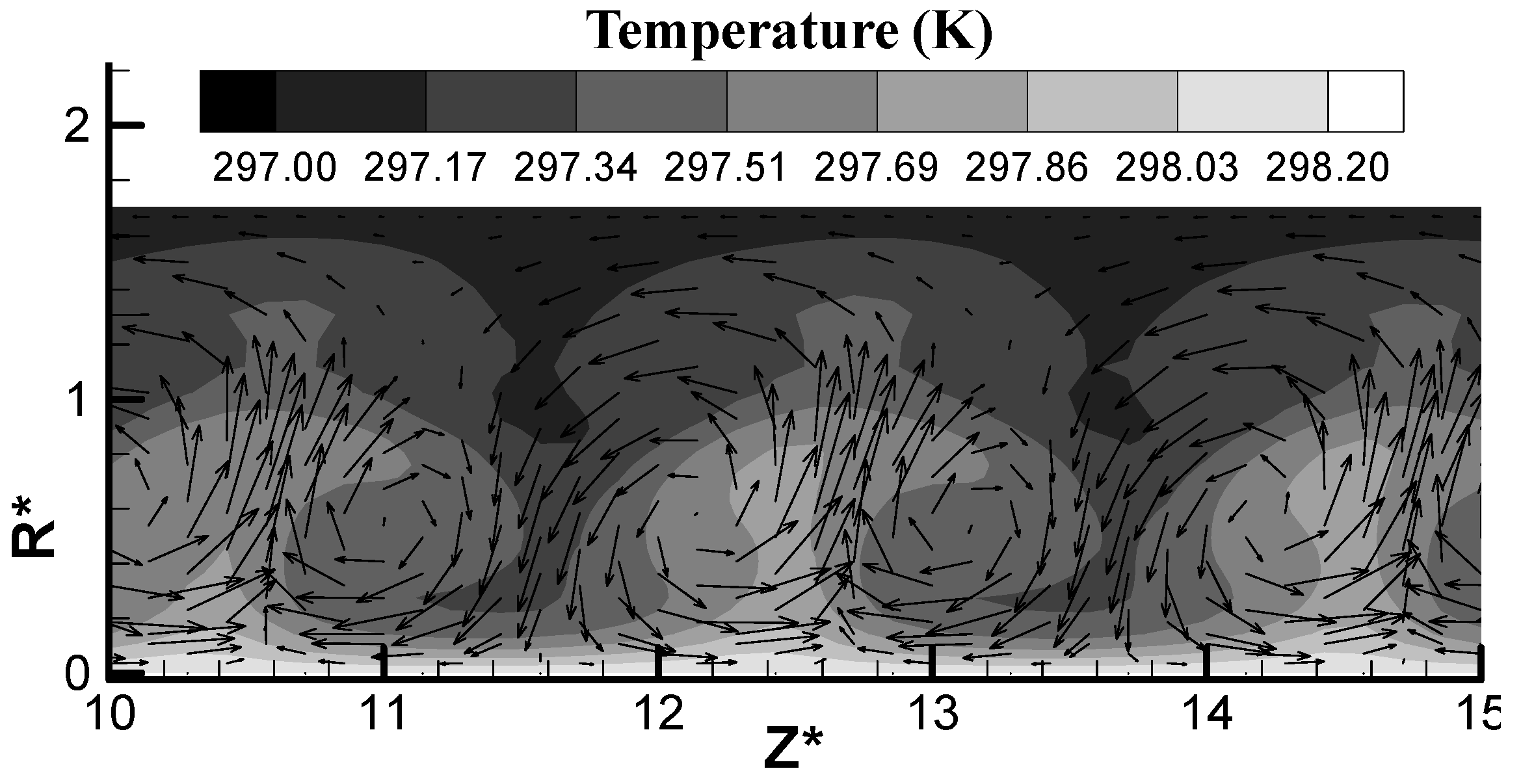
4.2. Characteristic of Flow and Heat Transfer Process in Plain Model

Figure 10 shows the velocity field of the vortex pair, and the background represents the temperature distribution, the black color represents the lower temperature and the white color represents the higher one. It was found the area of the space between the vortex pairs to the inner cylinder wall had a bigger temperature gradient, where the heat transfer intensity was stronger, and the space between two vortices in a vortex pair to the inner cylinder wall had a smaller temperature gradient, where the heat transfer intensity was weaker.
Figure 10. Velocity field and temperature distribution of a vortex pair.
Energies 08 01958 g010
Figure 11 shows the heat flux distribution in the inner cylinder wall along the axial direction, and it was found the heat flux distribution has a periodic changing feature. The crest and trough number of the heat flux distribution is the same as that of the radial velocity distribution. When the outer radial velocity has its maximum value, the heat flux on the inner cylinder has its minimum value. It was concluded that the area between two vortices in a vortex pair has the smallest heat transfer intensity, which is increasing along both sides, and has the biggest heat transfer intensity in the area between two vortex pairs. The area-weighted average surface heat flux of inner cylinder was 402.4 w/m2.
Figure 11. Heat flux along axial direction at T1.
Energies 08 01958 g011
Figure 12 shows the radial and axial velocity profile along the axial direction in different radial positions. When R* = 0.2, the radial velocity profile decreased slightly with the existence of the high temperature conditions near the inner wall, and the axial velocity increased with the existence of convection flow. In the middle position of the annulus gap, the convection flow had nearly no effect on the radial velocity, but increased the axial velocity obviously.
Figure 12. Radial and axial velocity along axial direction: (a) R* = 0.2; (b) R* = 0.5.
Energies 08 01958 g012

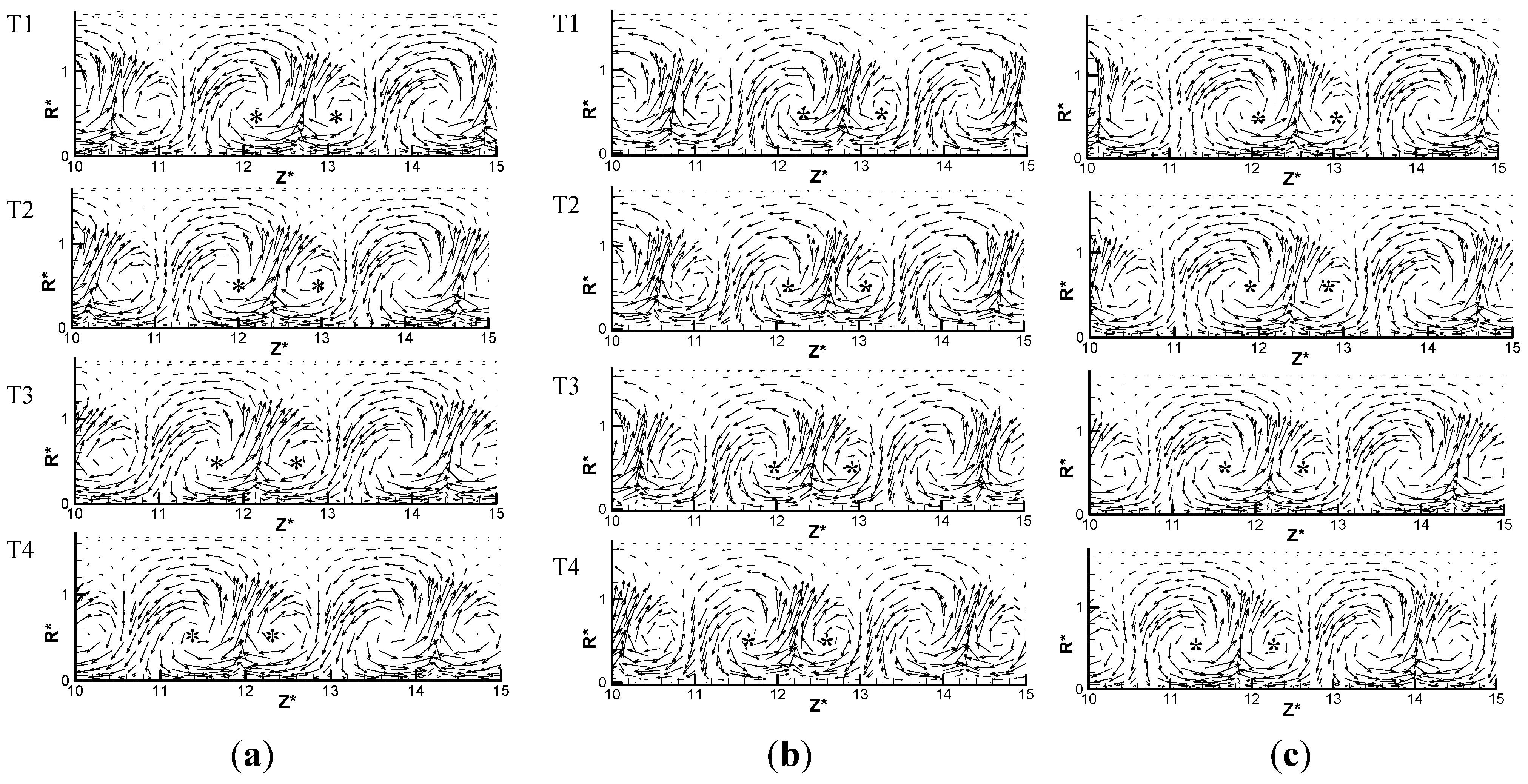
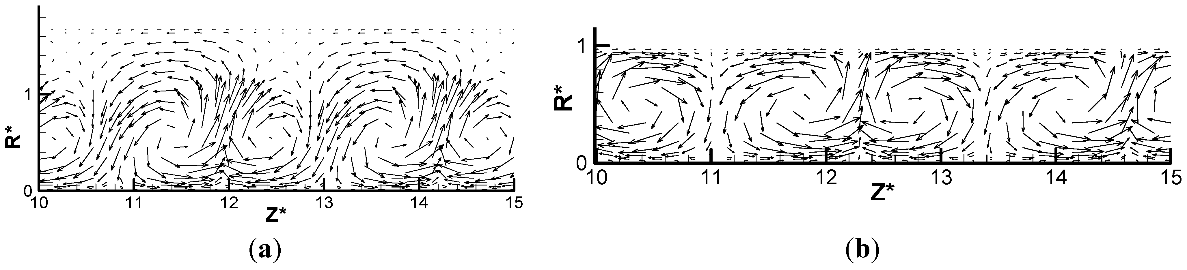
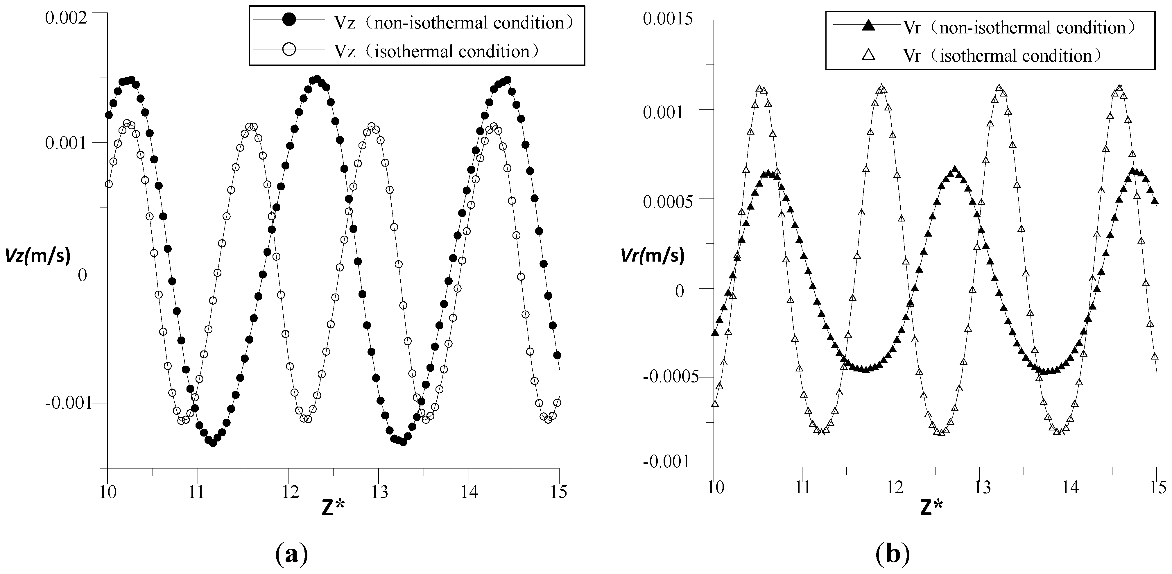
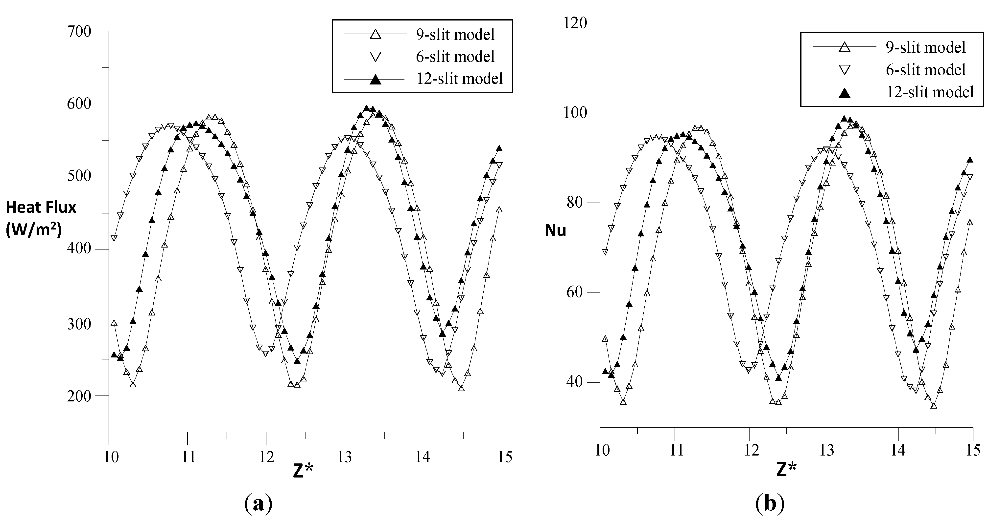
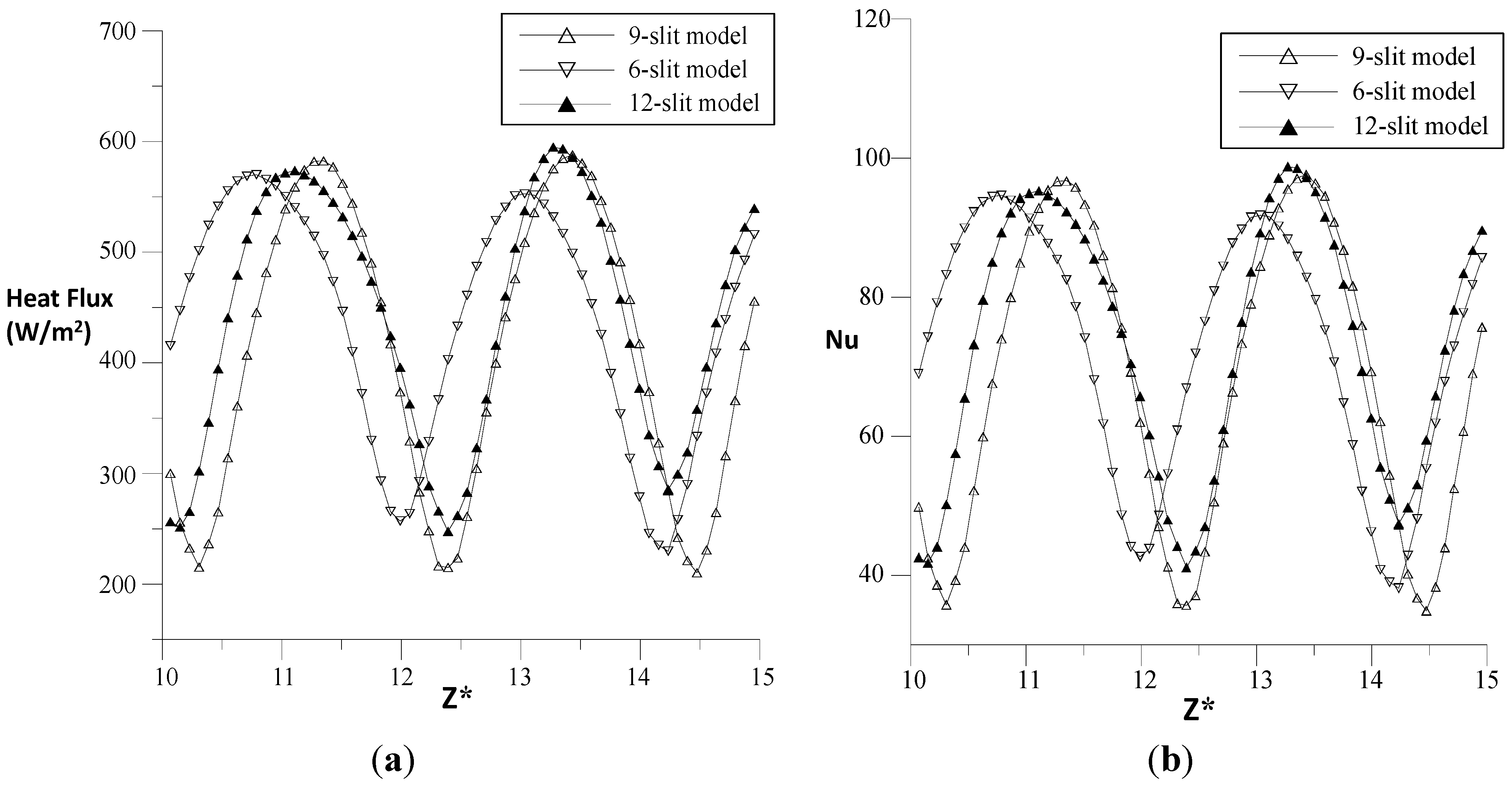
4.3. Flow Field Distribution in Slit Models

Figure 13 shows the velocity distribution at different times for the 6-slit, 9-slit and 12-slit models at Re = 110. This flow field has the feature of helical vortex flow, and two counter-rotating vortices which move helically along the axial direction appeared. The flow in the annulus gap expanded into the slit space, and the vortex size became larger compared with that of the plain model. The vortices with counterclockwise rotation were larger than the clockwise rotation ones, which was the same phenomenon as that seen in the plain model. The vortices’ axial motion velocity was 1.98 mm/s in the 12-slit model, and about 1.63 mm/s in the 6-slit model.
Figure 13. Instantaneous velocity fields in slit models at Re = 110: (a) 12-slit model; (b) 6-slit model; (c) 9-slit model.
Energies 08 01958 g013
Figure 14 shows the flow field of 12-slit model in different circumferential planes at Re = 110. Figure 14a is the velocity field in the slit wall region, and Figure 14b is the velocity field away from the slit wall region. It was found that the counterclockwise vortices in both figures were larger than the clockwise ones because of the temperature gradient effect.
Figure 14. Instantaneous velocity in different circumferential planes. (a) In the slit wall region; and (b) Away from the slit region.
Energies 08 01958 g014
Figure 15 shows the temperature distribution in the 6-slit model, where the higher temperature area in the annulus gap was between two vortices in a vortex pair, and the temperature gradient between this area and the inner cylinder wall was small. The fluid in the space of the slit wall area has a lower temperature compared to that in the annulus gap. To compare the temperature distribution in the 6-slit model to the plain model, it was found that the higher temperature area in the slit model was smaller than that of the plain model, and there was larger temperature gradient between the fluid area and the inner cylinder wall in the 6-slit model, which had stronger heat exchange ability.
Figure 15. Velocity field and temperature distribution in 6-slit model.
Energies 08 01958 g015
Figure 16, Figure 17 and Figure 18 shows the axial and radial velocity profile in 6-slit model at different radial positions, the R* is 0.2, 0.5 and 0.8 respectively. From Figure 16, it was found the axial velocity increases with the existence of a temperature gradient, but the radial velocity decreased because of the heat transfer process, and when R* is 0.2, the temperature is highest among three different radial positions. Because of the high temperature, the radial velocity at this position was weakened.
Figure 16. Axial and radial velocity profile in 6-slit model at R* = 0.2: (a) Axial velocity; and (b) Radial velocity.
Energies 08 01958 g016
From Figure 17, both axial and radial velocity in the center position of the annulus gap slightly increased with the existence of the temperature gradient. From Figure 16, Figure 17 and Figure 18, it was found the axial velocity at this position slightly increased, but the radial velocity increased by 200% because of the temperature gradient effect.
Figure 17. Axial and radial velocity profile in 6-slit model at R* = 0.5: (a) Axial velocity; (b) Radial velocity.
Energies 08 01958 g017
Figure 18. Axial and radial velocity profile in 6-slit model at R* = 0.8: (a) Axial velocity; and (b) Radial velocity.
Energies 08 01958 g018
Figure 19 shows the heat flux and Nusselt number distribution of different slit models along the inner cylinder wall. The two figures had the same trends. It was found the maximum heat flux increased as the slit number increased. The area-weighted average surface heat flux on the inner cylinder of 6-slit, 9-slit and 12-slit models was 421.2, 439.1 and 459.5 w/m2, respectively. In this study, the temperature of the inner and outer cylinder was kept constant, if the heat flux on the inner cylinder was the biggest, which means the inner cylinder wall generate the most amount of heat among all the models. When the inner cylinder was kept at a constant temperature, the additional heat was transferred to the outside environment through the outer cylinder, so more the heat flux generated by the inner cylinder, the better heat transfer ability that model had. From the area-weighted average surface heat flux of each model, it was found the 12-slit model had the best heat transfer ability, which was increased by 14.2% compared to the plain model.
Figure 19. Heat flux and Nusselt number along axial direction in different slit models. (a) Heat flux distribution; and (b) Nusselt number distribution.
Energies 08 01958 g019

5. Conclusions

In this paper, the Taylor vortex flow affected by a constant temperature gradient in plain and slit wall models was studied by experimental work and numerical simulation. The experimental and numerical simulation results were compared, which proved that the CFD method used in this paper is reliable. The following conclusions were obtained by comparing the results of different models: the flow field distribution at different times in slit models was analyzed at Re = 110. The vortices in the annulus gap were found to have a motion along the axial direction, which is the feature of helical vortex flow. In the plain model, the vortex size did not affect the heat transfer process considered in this study, and the space between adjacent vortex pairs had stronger heat transfer intensity. The heat flux in the inner cylinder wall along the axial direction did not remain constant any longer, and had periodically changing features. In the 6-slit model, the axial and radial velocity distribution in different radial positions was obtained, and except for the radial velocity at R* = 0.2, the velocity at other two radial positions was enhanced by the heat transfer process, especially at R* = 0.8, the radial velocity increased by 200% compared to the isothermal condition. By calculating the heat flux generated by the inner cylinder, it was found the heat flux had a maximum value in the 12-slit model, and this model has the best heat transfer ability, which was increased by 14.2% compared to the plain model.

Acknowledgments

This work was supported by National Natural Science Foundations of China (51206062), China Postdoctoral Science Foundation (2013M540420), Six talent peaks project in Jiangsu Province (ZBZZ-016), Specialized Research Fund for the Doctoral Program of Higher Education (20113227120012) and A Project Funded by the Priority Academic Program Development of Jiangsu Higher Education Institutions (PAPD). One of the authors (Hyoung-Bum Kim) was supported from Basic Science Research Program (2012-008918) through the National Research Foundation of Korea.

Author Contributions

All authors contributed to this work by collaboration. Dong Liu was the main author of this manuscript. Ying-Ze Wang assisted in the design of optimization methods to this study. Hyoung-Bum Kim and Ai-Kun Tang provided some useful suggestions in the construction of paper. The whole project was supervised by Wei-Dong Shi. All authors revised and approved the publication.

Conflicts of Interest

The authors declare no conflict of interest.

References

  1. Taylor, G.I. Stability of a viscous liquid contained between two rotating cylinders. Philos. Trans. R. Soc. A 1923, 223, 289–343. [Google Scholar] [CrossRef]
  2. Tzeng, S.C.; Ma, W.P.; Lin, C.W. Experimental investigation of lubrication and cooling effects of high-speed rotating machines. Int. J. Adv. Manuf. Technol. 2007, 35, 394–399. [Google Scholar] [CrossRef]
  3. Lepiller, V.; Goharzadeh, A.; Prigent, A.; Mutabazi, I. Weak temperature gradient effect on the stability of the circular Couette flow. Eur. Phys. J. B 2008, 61, 445–455. [Google Scholar] [CrossRef]
  4. Poncet, S.; Haddadi, S.; Viazzo, S. Numerical modeling of fluid flow and heat transfer in a narrow Taylor-Couette-Poiseuille system. Int. J. Heat Fluid Flow 2011, 1, 128–144. [Google Scholar] [CrossRef]
  5. Kang, C.W.; Yang, K.S.; Mutabazi, I. The effect of radial temperature gradient on the circular-Couette flow. Trans. KSCFE 2009, 14, 16–24. [Google Scholar]
  6. Hayase, T.; Humphrey, J.A.C.; Greif, R. Numerical calculation of convective heat transfer between rotating coaxial cylinders with periodically embedded cavities. J. Heat Transf. 1992, 114, 589–597. [Google Scholar] [CrossRef]
  7. Lee, Y.N.; Minkowycz, W.J. Heat transfer characteristics of the annulus of two-coaxial cylinders with one cylinder rotating. Int. J. Heat Mass Transf. 1989, 32, 711–722. [Google Scholar] [CrossRef]
  8. Liu, D.; Lee, S.H.; Kim, H.B. Effect of a constant radial temperature gradient on a Taylor-Couette with axial wall slits. Fluid Dyn. Res. 2010, 42, 065501. [Google Scholar] [CrossRef]
  9. Liu, D.; Kang, I.S.; Cha, J.E.; Kim, H.B. Experimental study on radial temperature gradient effect of a Taylor-Couette flow with axial wall slits. Exp. Therm. Fluid Sci. 2011, 35, 1282–1292. [Google Scholar] [CrossRef]
  10. Liu, D.; Zhu, J.; Wang, Y.Z. Numerical Simulation of the slit wall effect on flow stability in Taylor Vortex Flow Regime. J. Drain. Irrig. Mach. Eng. 2014, 3, 1–5. [Google Scholar] [CrossRef]
  11. Liu, D.; Wang, Y.Z.; Kim, H.B. Slit wall effect on the stability of wavy vortex flow. Adv. Mech. Eng. 2014, 853069. [Google Scholar] [CrossRef]
  12. Cole, J.A. Taylor-vortex instability and annulus-length effects. J. Fluid Mech. 1976, 75, 1–15. [Google Scholar] [CrossRef]
  13. Wereley, S.T.; Lueptow, R.M. Spatio-temporal character of non-wavy and wavy Taylor-Couetteflow. J. Fluid Mech. 1998, 364, 59–80. [Google Scholar] [CrossRef]
  14. Lee, S.H.; Chung, H.T.; Park, C.W.; Kim, H.B. Experimental investigation of the effect of axial wall slits on Taylor-Couette flow. Fluid Dyn. Res. 2009, 41, 045502. [Google Scholar] [CrossRef]

