
On the Scale-up of Gas-Hydrate-Forming Reactors: The Case of Gas-Dispersion-Type Reactors

Department of Mechanical Engineering, Keio University, Yokohama 223-8522, and BNE Mutsuura Laboratory, Yokohama 236-0031, Japan
Energies 2015, 8(2), 1317-1335; https://doi.org/10.3390/en8021317
Submission received: 25 December 2014
/
Accepted: 24 January 2015
/
Published: 10 February 2015
Abstract
:For establishing hydrate-based technologies for natural-gas storage/transport, CO2 capture from industrial flue gases, etc., we need appropriate guidelines for the scale-up of hydrate production/processing equipment from laboratory scales to industrial scales. This paper aims to provide technical remarks on the scale-up of hydrate-forming reactors, the central components of hydrate production/processing equipment, particularly focusing on such a reactor design that hydrate-forming gas is dispersed in an aqueous phase which is either stirred in a tank or forced to flow through a tube. Based on the principles of classical fluid mechanics and heat-transfer analysis, the paper derives semi-empirical formulas that show how the capacity for heat discharge from each reactor and the power for operating the reactor are required to change with an increase in its size. Consequently, it is concluded that the stirred-tank design is unfavorable for significant scale-up and that the scale-up of tubular reactors should be made without significantly increasing the in-tube flow velocity.
1. Introduction
Clathrate hydrates (or gas hydrates) are crystalline solid compounds each formed from host water molecules and guest molecules of some other substance (or substances) in categories of light hydrocarbons, acid gases, etc. Various engineering applications of such hydrates have been proposed in the last seven decades. These potential applications of hydrates include the storage and transport of natural gas in the form of a hydrate, the desalination by separating hydrate crystals formed in seawater, the cool energy storage for residential air-conditioning utilizing the endothermic hydrate dissociation, the hydrate-based separation of carbon dioxide (CO2) and sulfur dioxide (H2S) from exhaust flue gas of fossil-fuel power plants. A concise but comprehensive overview of these applications is provided by Sloan and Koh [1]. One of the major engineering tasks for putting such as-yet potential applications to practical use is to establish hydrate-forming technology suitable for each application. Various types of hydrate-forming reactors have already been constructed and tested. Most of these studies were done in laboratories. Research projects in which bench-scale or pilot-plant-scale hydrate-forming reactors were constructed and operated are very limited (see, for example, [2,3,4,5]), and details of the results of such projects have been seldom reported in a systematic form in the archival literature. Therefore, we often need to estimate a priori how the reactor designs successfully applied to laboratory-scale equipment can be scaled-up for industrial use and, if actually constructed, how such scaled-up reactors can be operated. The general scale-up strategies for conventional chemical reactors (see, for example, [6]) may be instructive for us to take the first step in considering the scale-up of hydrate-forming reactors. Nevertheless, more specific guidelines for the scale-up of hydrate-forming reactors may be desirable as an aid in designing industrial-scale reactors. This paper describes an engineering view, mainly based on the principles of fluid mechanics and convective heat transfer, on the scale-up of hydrate-forming reactors, and provides some practical remarks on the scale-up of gas-dispersion-type reactors, i.e., a class of reactors so designed as to disperse a hydrate-forming gas in a continuous phase of liquid water.
2. General Consideration on Reactor Design
2.1. Modes of Reactor Operation
We restrict our interest in this paper to the case that a hydrate-forming substance, which may be a single species or a mixture of two or more species, in the gaseous state and water in the liquid state are supplied into each reactor and that gas and liquid phases remain inside the reactor during each hydrate-forming operation. The operation may be in any of the following three modes:
- (a)
- a batch operation during which neither the hydrate-forming gas nor water is discharged from, or supplied to, the reactor till the end of the operation, thereby causing a continuous decrease in pressure inside the reactor with the progress of hydrate formation;
- (b)
- a semi-batch operation during which only the hydrate-forming gas is continuously supplied to the reactor for compensating for the loss of the gas due to the hydrate formation, thereby maintaining an almost constant pressure inside the reactor; or
- (c)
- a continuous operation during which both the hydrate-forming gas and water are continuously supplied to the reactor and a hydrate slurry (i.e., a mixture of the formed hydrate and the aqueous liquid) is continuously discharged from the reactor, thereby leaving the pressure and the gas–liquid–hydrate ratio inside the reactor practically invariant.
2.2. Devices for Gas–Liquid Mixing and Heat Discharge
There are two general conditions required for reactors to yield sufficiently high hydrate-production rates: (1) good mixing of the hydrate-forming gas and liquid water; and (2) effective cooling for discharging the heat released by the hydrate formation [7]. Any reactor design that fails to satisfy both of these conditions seems to be unsuitable for industrial use.
The most common means for satisfying the former condition is to disperse either the gas or liquid water in the other at the cost of applying a mechanical work to each reactor. The injection of discrete gas bubbles in a continuous aqueous phase [3,4,5,8] or the spraying or sprinkling of liquid water in a continuous gas phase [9,10,11,12,13] significantly increases the gas–liquid interfacial area across which the gas dissolves into the aqueous phase, thereby promoting the hydrate formation at, or in the vicinity of, the interface. Such an external work for dispersing either the fluid phase into the other may be neglected in the case that a surfactant is added to the aqueous pool occupying a lower portion of the tank-shaped reactor, resulting in a capillarity-driven, spontaneous hydrate-layer growth over the reactor wall above the free surface of the quiescent aqueous pool (consult, for example [14,15,16]). The decrease in the wall-surface-to-volume ratio with the scale-up of such a reactor may be offset by vertically suspending metal plates in the reactor from its top and dipping them in the aqueous pool such that these plates can serve as additional sites for the hydrate-layer growth and, at the same time, as the cooling fins for discharging heat to the outside of the reactor [15,17,18]. An alternative option for apparently omitting the mechanical work for gas–liquid mixing is to use fixed-bed-type reactors. This type of reactor using silica gels, silica sand, polyurethane foam, etc., as the packing materials has been successfully used in recent laboratory studies addressing the feasibility of hydrate-based CO2 capture from flue gas [19,20,21]. In this case, the packing that fills each reactor may be viewed as an equivalent to a static mixer that provides intensive gas–liquid mixing at the cost of imposing an additional pressure loss in the gas flow, thereby indirectly using mechanical work.
As for the latter condition, various methods and/or equipment designs for the heat discharge have been devised and actually tested. In general, these methods may be broadly divided into two types: one is to directly cool each reactor itself [4,5,10] or a specific location inside the reactor [22], and the other is to pump the liquid water (or a hydrate slurry) through an external loop in which a heat exchanger is installed [8,9,11]. The latter type may be extended such that, in addition to the water circulation, a hydrophobic liquid coolant is circulated through a separate loop to be cooled to a temperature far below the water freezing point, thereby conveying a large cool energy to the reactor [23,24,25]. The two types may be jointly used for cooling a single reactor unit [3].
2.3. Structural Designs and Scale-up of Reactors
Various structural designs of hydrate-forming reactors have been reported in the literature. With the exception of a few, they are classified into two types: (a) the gas-dispersion type in which a hydrate-forming gas is injected into a continuous aqueous phase, turning into discrete bubbles or slugs; and (b) the liquid-dispersion type in which liquid water, or an aqueous liquid, is sprayed or sprinkled into a continuous gas phase, turning into tiny droplets [7]. In either of these two types, each reactor may be in the form of a tank, in which the major proportion of the aqueous liquid relevant to the hydrate-forming operation is contained, or in the form of a tubular conduit, or conduits, through which the aqueous liquid and the hydrate-forming gas were forced to flow. Typical liquid-dispersion-type reactors are composed of high-pressure chambers and water-circulation/cooling assemblies that enable the continuous, downward spraying of pre-cooled water from a spray nozzle, or nozzles, installed in the top portion of each chamber. Such a reactor design has a marked advantage over others concerning the reactor scale-up. That is, the scale-up can be made by simply enlarging the horizontal dimension of the chamber and increasing the number of spray nozzles to be installed in the chamber. If the specifications of each nozzle are unchanged, we can readily predict, on the basis of prior operating experience with a small prototype reactor, the hydrate-production rate and the power required for circulating water during the operation of a scaled-up reactor. In contrast, reactor designs in the category of the gas-dispersion type encounter a difficulty in planning the reactor scale-up; this is because, with such designs, the reactor-scale dependences of the hydrate-production rate and the power required for reactor operation are complicated by the nature of hydrodynamic and thermal interactions between the aqueous phase and the reactor wall. Hence, we focus our attention hereafter on the issue of the scale-up of two typical reactor designs in the gas-dispersion-type category: one employs gas bubbling into a stirred aqueous-liquid pool filling the lower portion of a cylindrical tank, and the other is to make the aqueous liquid and a hydrate-forming gas concurrently flow through a tube, or tubes, taking the form of a dispersed bubble flow.
3. Specific Remarks on Reactor Scale-up
3.1. Stirred-Tank Reactors
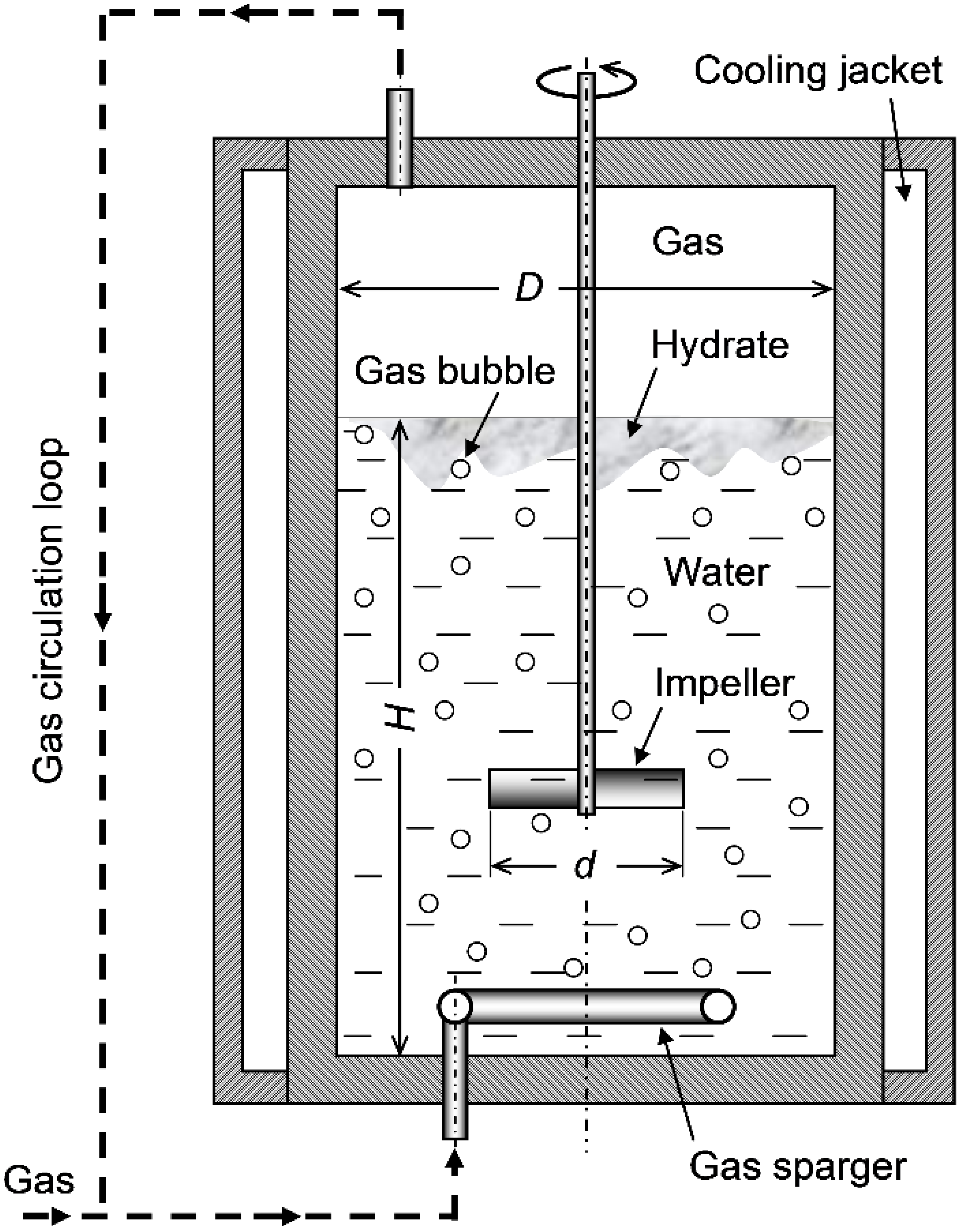
The stirred tanks used for gas–liquid mixing operations in laboratory setups or industrial processes are various in their design, which may be specified in terms of the tank geometry, the types of impellers for stirring, the types of gas-injection devices, the types of heating/cooling devices, etc. The stirred tanks that we assume in the following discussion are vertically oriented cylindrical tanks each equipped with a rotating stirrer inserted into the tank along its central axis (see Figure 1). The impeller fixed onto the stirrer shaft may be a marine propeller, a turbine or a paddle. The tank may or may not be equipped with baffles on its inside wall. A hydrate-forming gas may be bubbled into the tank from a perforated-plate or, as illustrated in Figure 1, perforated-ring sparger placed below the impeller. Alternatively, the gas may be bubbled from the impeller itself which is connected to a hollow shaft through which the gas is being supplied [4,26]. The tank is sheathed by a coolant jacket (or, alternatively, wrapped by a cooling coil) for continuously cooling its contents, thereby discharging the heat released by the hydrate formation to the outside of the tank. The parallel use of any other cooling device such as an external liquid-circulation loop [8] is not considered.
The heat transfer from the aqueous pool inside a reactor to the coolant flowing in the external jacket of the reactor includes the following three processes connected in series: the convective heat transfer from the bulk of the aqueous pool to the inside surface of the reactor wall, the conductive heat transfer across the wall, and the convective heat transfer from the outside surface of the wall to the coolant. In the following analysis and discussion, however, we exclusively consider the first process which directly depends on the reactor size and the stirrer operation. Moreover, we approximate the aqueous pool as a single phase of a Newtonian liquid, neglecting any multiphase effects on the stirrer-induced flow and the convective heat transfer from the bulk of the pool to the reactor wall. Therefore, the discussion hereafter may not apply with reasonable accuracy to the situation in which gas bubbles or slugs are very densely dispersed in the pool and/or the bulk of the pool is occupied by a dense slurry of formed hydrate crystals.
Figure 1.
Schematic illustration of a stirred-tank reactor used in a semi-batch hydrate-forming operation.
Figure 1.
Schematic illustration of a stirred-tank reactor used in a semi-batch hydrate-forming operation.
Numerous studies have been reported about the heat transfer between the tank wall and the bulk of the liquid stirred inside the reactor. Following is the classical correlation given by Chilton et al. [27], which is widely recognized as a practical tool for estimating h, the heat transfer coefficient averaged over the wetted tank wall:
where , , ; D is the inside diameter of the tank; d is the diameter of the impeller (or impellers) installed in the tank; N is the rotational speed (revolutions per second) of the impeller; and the physical properties of the liquid (the Prandtl number Prl, thermal conductivity kl, kinematic viscosity νl, and dynamic viscosity μl) are all evaluated at the bulk temperature inside the tank except for μls, the viscosity at the surface temperature of the tank wall. These properties may be approximated by those of pure water, if the volume fractions of the gas and hydrate dispersed in the pool are sufficiently low. Otherwise, these properties should be the effective properties of an aqueous suspension of gas bubbles and hydrate particles. The lead constant C1 may vary in the range from ~0.3 to ~1.2, depending on the geometric details of the tank and the impeller [27]. Because the temperature dependency of water is relatively weak, the viscosity ratio Vil may be deleted from Equation (1), thereby simplifying the heat transfer correlation as follows:
Limiting our interest to the reactor scale-up with a geometric similarity, we assume C1 to be an invariable. An issue concerning this assumption is discussed in the Appendix. As , the ratio of d to D, is fixed in the scale-up of the present interest, Equation (2) can be rewritten as follows:
where the second constant C2 denotes a physical-properties group defined as
In parallel with the heat transfer issue discussed above, we need to know how , the power required for driving the stirrer, depends on the size of the reactor (d and/or D) as well as on N. Based on the definition of Po, the “power number” or the impeller drag coefficient, is expressed as follows:
where ρl denotes the mass density of the liquid (water or a water-based suspension of gas bubbles and hydrate particles). The variation of Po with Red is different depending on the geometry of the tank and the impeller and also on the magnitude of [28,29]. For baffled tanks widely used in industrial mixing operations, Po for a given impeller geometry and hardly changes as Red exceeds 5 × 10³. For unbaffled tanks, Po continues to decrease gradually as Red increases to the order of 106. However, the decrease in Po corresponding to an increase in Red from 103 to 106 is by a factor of only ~2 at the maximum [28,29]. Therefore, we may replace Po as a function of Red with , the mean Po value over an estimated Red range relevant to the operation of the scaled-up reactor, for the purpose of the order-of-magnitude estimation of for the scaled-up reactor. With being fixed, Equation (5) can be rewritten as follows:
in which the parenthesized group of quantities, , is assumed to be constant.
The questions that we should deal with next are (a) how N should be changed with an increase in D in order to maintain a sufficient hydrate-forming capacity relative to the size of the reactor, and (b) how these changes in D and N will lead to a change in . The answer to question (a) may vary depending on our view as to what the primary rate-controlling factor for the hydrate formation in the tank is. [The answer to question (b) is automatically deduced from the answer to question (a)]. Here, we examine the following two cases: case I in which the heat discharge to the outside of the tank is assumed to be the primary factor, and case II in which the gas–liquid mixing inside the tank and the resulting interphase mass transfer of the hydrate-guest substance are assumed to be the primary factor.
Case I: Size-Independent Liquid-to-Wall Thermal Conductance per Unit Volume
The thermal conductance for the convective heat transfer from the bulk of the liquid pool to the inside tank-wall surface is given by , where H denotes the depth of the liquid pool (see Figure 1). Note that we neglect the heat transfer through the walls at the bottom and the top of the tank, because these walls are generally covered by thermal insulation layers and are not in contact with any active-cooling devices. Thus, the specific thermal conductance (STC), i.e., the thermal conductance per unit volume of the liquid phase, is, if we neglect the displacement by the gas sparger and the impeller assembly submerged in the pool, expressed as
That is, in order to keep STC unchanged irrespective of an increase in D, h must be increased in proportion to D as follows:
Combining Equation (8) with Equation (3), we obtain the following N versus D relation:
Substituting Equation (9) into Equation (6) leads to the following equation which shows an extremely strong dependence of on D:
Obviously, it is technically impractical to increase N in proportion to D, thereby increasing in proportion to D8. If this was actually done, the rate of mechanical-energy dissipation per unit liquid-phase volume, , would increase in proportion to D5. This would further increase the heat-discharge loads for scaled-up reactors.
Case II: Size-Independent Gas–Liquid Flow Pattern Inside Tanks
The flow pattern in a stirred tank, in which a gas is continuously bubbled at a constant volumetric flow rate , varies depending on two dimensionless numbers—the Froude number and the flow number where g denotes the acceleration due to gravity. In the literature, three flow regimes are mapped on an Fr versus Fl diagram (see, for example, [30,31]). The lower border of the fully recirculated regime on the Fr versus Fl diagram prepared by Lee and Dudkovic [31] is represented with a reasonable accuracy by the following equation:
Based on this finding, we assume that geometrically and hydrodynamically similar gas–liquid flow will be established in tanks which may be different in size but are geometrically similar to each other, if they are operated such that the following condition is satisfied:
where C3 is a constant (≥4.4) common to all of these tanks. Equation (12) can be rearranged into the following form:
If is controlled such that the superficial gas velocity, , is held constant irrespective of D, Equation (13) reduces to
Substituting Equation (14) into Equations (3) and (6), we obtain
Alternatively, may be so controlled as to be proportional to the volume of the liquid phase, thereby maintaining , the superficial gas residence time in the liquid phase, constant. If this is the case, Equation (13) reduces to
where and are constants expressing H / D, the height-to-diameter ratio of the liquid phase inside the reactor, and , the volumetric gas-flow rate per unit volume of the liquid phase, respectively. Note that . Substituting Equation (17) into Equations (3) and (6), we obtain
The requirement for maintaining the specific thermal conductance for heat discharge irrespective of the reactor size [Equations (8)–(10) for case I] may be surplus to that for maintaining a sufficient gas–liquid mixing. On the other hand, the requirement for maintaining a sufficient gas–liquid mixing [Equations (14)–(16) or Equations (17)–(19) for case II] must be insufficient for maintaining the specific thermal conductance for heat discharge against a decrease in the surface-to-volume ratio due to an increase in the reactor size. We assume that the N versus D or versus D relation with which the hydrate-forming capacity per unit volume is actually held almost constant falls between the above two requirements. This assumption is supported, though indirectly, by several experimental observations that the actual hydrate-formation rates were only from a quarter to half of the corresponding rates that the heat-discharge capacities of used experimental systems allowed [7,22,24]. It turns out based on this assumption that the scale-up of a stirred-tank reactor causing no practical change in the hydrate-forming capacity per unit volume entails an increase in in proportion to D to the power higher than 3.2, but lower than 8. The conventional way of stirred-tank scale-up that maintains the power input per unit volume nearly constant [6] is, as long as the scale-up with a geometric similarity is concerned, identical to the relation that ∝ D3, thereby leading to a failure to provide sufficient stirring power for maintaining the hydrate-forming capacity per unit volume constant. The necessity for the very sharp increase in the stirring power with reactor scale-up makes the use of stirred-tank reactors for industrial-scale hydrate production technically and/or economically unfavorable.
3.2. Tubular Reactors
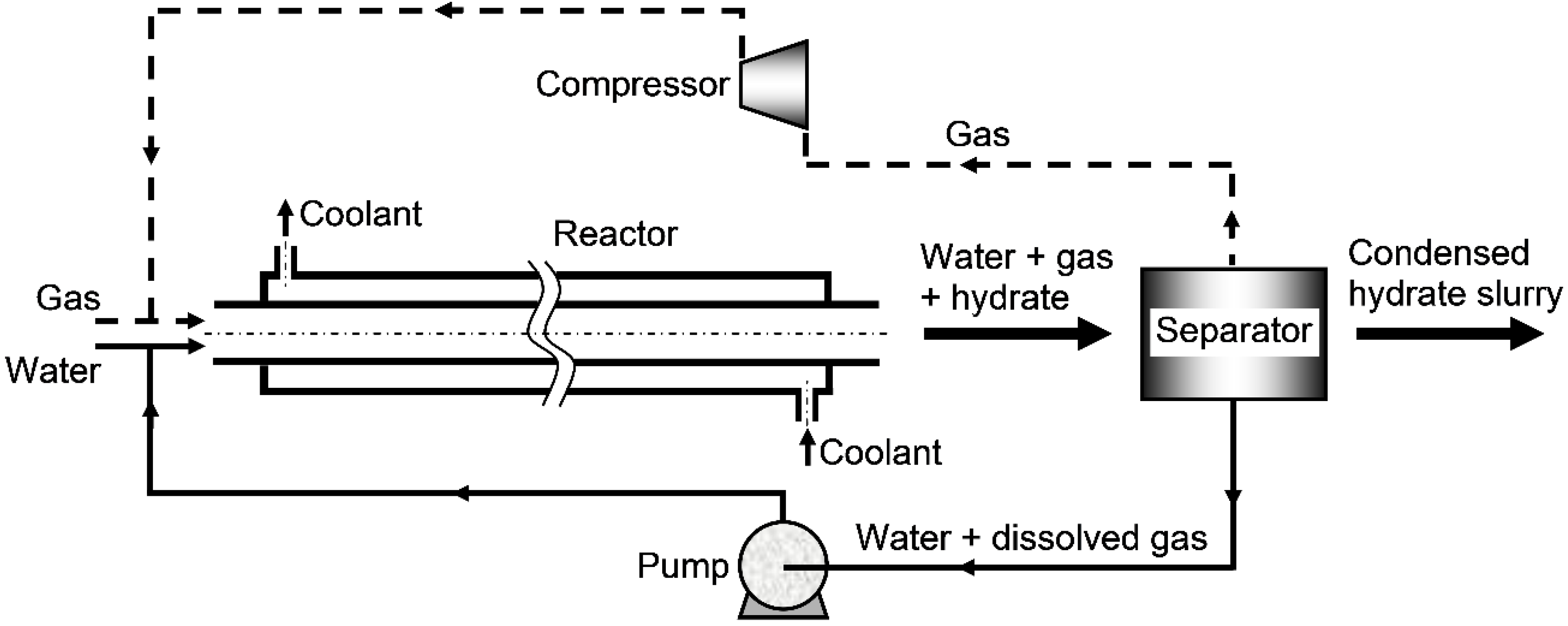
The tubular reactors that we consider in this section are limited to those having the simplest structural design. That is, each reactor is assumed to be composed of a circular constant-diameter tube or a bundle of such tubes arranged in a row, through which liquid water and a hydrate-forming gas are forced to flow together, and a cooling jacket enclosing the tube or the tube bundle (see Figure 2). The reactors equipped with variable diameter sections (divergent or convergent-divergent nozzles, Venturi tubes, etc.) within the axial span for hydrate formation are excluded. In contrast to stirred-tank reactors which can be used in any of the three operating modes (a)–(c) outlined in Section 2.1, tubular reactors are generally considered to fit only to mode (c), the continuous operation mode, because of the necessity of maintaining the high fluidity of the multiphase medium flowing inside the tubes throughout each hydrate-forming operation. A typical layout of a tubular-reactor-based hydrate-production system for the continuous operating mode is schematically illustrated in Figure 3.
Figure 2.
Sectional view of a tubular hydrate-forming reactor having the simplest coaxial-tube structure.
Figure 2.
Sectional view of a tubular hydrate-forming reactor having the simplest coaxial-tube structure.
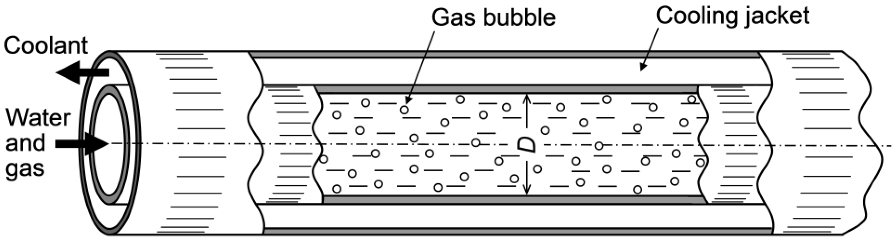
Figure 3.
Layout of a hydrate-forming system employing a tubular reactor.
When we focus on the aspect of discharging the heat released by hydrate formation, tubular reactors may be regarded as shell-and-tube heat exchangers, in each of which liquid water and a hydrate forming gas are flowing on the tube side while a coolant is flowing on the shell side. The coolant may be in a simple countercurrent flow in an unbaffled shell as illustrated in Figure 2 [3,32] or a more complex flow in a baffled or finned shell [33]. Alternatively, the coolant may be jetted or sprayed onto the tube wall from nozzles periodically aligned along the tube axis (or axes) in order to obtain a higher shell-side heat transfer coefficient. The shell-side heat transfer coefficient will be significantly increased by employing evaporative cooling with a coolant having a boiling point close to the hydrate dissociation temperature inside the tube. Here, we focus on the heat transfer inside each tube installed in a tubular reactor. For simplicity, we assume that the tube to be straight and free from any flow-interfering devices (such as flow meters, valves, twisted tape inserts, Kenics mixers, spiral fins on the inside tube wall, etc.) over its axial span L relevant to the tube-side convective heat transfer. The capacity of the heat discharge from the inside to the outside of the tube relative to the heat-capacity flow rate through the tube can be evaluated in terms of the number of transfer units (NTU), a dimensionless modulus widely used in heat-exchanger analyses and design. The NTU for the system of our present interest is defined as follows:
where U is the overall coefficient for the heat transfer across the tube wall, A is the inside tube-surface area over the axial length L, is the mass flow rate of the gas or the liquid supplied to the tube, is the specific heat at constant pressure, and subscripts g and l stand for the gas and the liquid, respectively, flowing through the tube. Note that what we call “the liquid” here may be an aqueous suspension of hydrate particles instead of pure liquid water. Because NTU represents the system capacity for decreasing the specific enthalpy of the gas–liquid mixture during its flow through a given tubular reactor, it is reasonable to assume that the fraction of the formed hydrate in the effluence from the reactor is primarily dependent on the NTU value of the reactor. That is, NTU is considered to be a thermal index analogous to STC for a stirred-tank reactor.
Generally, the heat capacity rate of the gas flow, , is sufficiently low as compared to that of the liquid flow, . Hence, may be omitted from Equation (20). As the overall heat transfer coefficient, U, depends on both the tube-side gas–liquid flow and the shell-side coolant flow, we cannot estimate its value with a sufficient accuracy unless details of the tube–shell structure and the coolant-feeding operation are provided in advance. To avoid such a complexity regarding U, we illustrate below a case in which the shell-side heat transfer coefficient is sufficiently high and hence the major thermal resistance for the heat transfer lies on the tube-side flow. The NTU in this case can be expressed as
where D denotes the inside diameter of the tube (Figure 2). The heat transfer coefficient h must be dependent on the gas-to-liquid flow-rate ratio. However, if this ratio is relatively low and the dispersed bubble flow pattern is maintained over the axial span L, we may assume, to a first approximation for estimating h, the flow inside the tube to be a single-phase liquid flow. Based on the Chilton–Colburn analogy, h is related to the Darcy–Weisbach friction factor f as follows (see, for example, Ref. [34]):
where , ; uav is the liquid flow velocity averaged over the tube cross section; and kl and νl are the thermal conductivity and kinematic viscosity, respectively, of the liquid. For straight tubes having smooth surfaces, the following correlation can be used to approximate the f versus ReD relation in the range of ReD 2 × 10⁴ [34]:
Substitution of Equation (23) into Equation (22) leads to the following correlation which is often referred to as the Colburn equation in the literature:
Because Equations (23) and (24) are valid for the range of ReD 2 × 10⁴, the following formulation incorporating these correlations may be safely applicable for the reactor scale-up from a bench scale to a pilot-plant scale or a commercial-plant scale. On the other hand, one should be careful about its application to the scale-up from a laboratory scale to a bench scale, because Equations (23) and (24) tend to underestimate f and NuD, respectively, as ReD decreases from ~2 × 10⁴.
Using Equation (24), Equation (21) can be rewritten as
or in the form expressing the axial length L required for obtaining a prescribed value of NTU as
Besides the heat transfer issue discussed above, we need to evaluate the power required for pumping the liquid through the tube against the friction exerted on the tube wall along the axial length L. Considering the axial force balance over the length L, we can express as follows:
where Δp denotes the magnitude of the pressure drop over the length L and is related to f as
Substituting Equations (23) and (28) into Equation (27), we have
We can further rewrite this equation in order to relate to the NTU given by Equation (25) as follows:
or
Equation (30) or (31) provides us with a useful insight that required for maintaining the NTU at a prescribed level is proportional to or . In order to more specifically illustrate what Equations (26), (30) and (31) suggest in regards to the scale-up of tubular reactors, let the flow-related quantities (D, L, Nt, , uav and ) relevant to a given base-size reactor be marked by the subscript “0”, where Nt denotes the number of tubes arranged in parallel in each reactor. We select , the total mass-based liquid-flow rate through the reactor, as the representative index of the scale (or hydrate-forming capacity) of the reactor, implicitly assuming that the ratio of to is held constant irrespective of the scale-up, and let the magnification in [or ] relevant to the scale-up from the base-size reactor be denoted by J; i.e., where J denotes an arbitrary natural number. The magnification in is available by increasing either D2 (case 1) or uav (case 2) in proportion to J or by multiplying Nt (case 3). The magnifications in L, and required for maintaining the NTU unchanged irrespective of the magnification in by the factor of J have been deduced from Equations (26), (30) and (31) for each of the three cases (cases 1–3). The deduced results are demonstrated in Table 1. To help our intuitive recognition of these results, numerical examples for two specific magnifications in — J = 4 and 16 — are added to Table 1. In this table, we can obtain some implications which may be helpful for planning the scale-up of tubular reactors. First, there is no difference between case 1 and case 3 regarding the change in with the increasing J; i.e., in either case, linearly increases with the increasing J. However, an increase in L with the increasing J is inevitable in case 1, while it is avoided in case 3. The increase in (or ) with the increasing J is very sharp in case 2. Obviously, it is undesirable from the viewpoint of saving the system-operation cost to increase while changing neither D nor Nt. In case 1, we should be careful about the possible change in the gas–liquid flow pattern with an increase in D. This is because the lower limit of uav for maintaining the dispersed bubble flow pattern is known to increase with an increase in D [35]. That is, an increase in D leaving uav constant may cause a transition from the dispersed bubble flow pattern to the intermittent bubble flow or slug flow pattern, thereby deteriorating the gas–liquid mixing and the gas-to-liquid interphase mass transfer of the hydrate-guest substance. In order to maintain the dispersed bubble flow pattern inside each tube, appropriate control of uav depending on an increase in D may be necessary.

Table 1.
Magnifications in tube diameter (D), average water flow velocity (uav), number of tubes (Nt), tube length effective for heat discharge (L), and pumping power per each tube () required for maintaining the NTU unchanged irrespective of the magnification in the water mass-flow rate () by a factor of J (=an arbitrary natural number), 4 or 16; subscript “0” refers to the base-size reactor as a prototype for reactor scale-up.
| J | case 1 | J 1/2 | 1 | 1 | J 3/5 | J | J |
| case 2 | 1 | J | 1 | J 1/5 | J 3 | J 3 | |
| case 3 | 1 | 1 | J | 1 | 1 | J | |
| 4 | case 1 | 2 | 1 | 1 | 2.30 | 4 | 4 |
| case 2 | 1 | 4 | 1 | 1.32 | 64 | 64 | |
| case 3 | 1 | 1 | 4 | 1 | 1 | 4 | |
| 16 | case 1 | 4 | 1 | 1 | 5.28 | 16 | 16 |
| case 2 | 1 | 16 | 1 | 1.74 | 4096 | 4096 | |
| case 3 | 1 | 1 | 16 | 1 | 1 | 16 |
If the gas-to-liquid or the hydrate-to-liquid flow-rate ratio is not so low as to justify the single-phase tube-flow approximation, the magnitudes of f, NuD, NTU and may deviate from those predicted by Equations (23)–(25) and (29), respectively. However, the functional forms of these equations, i.e., the dependences of f, NuD, NTU and on ReD, presumably remain as they are, thereby causing little change in the results summarized in Table 1.
4. Concluding Remarks
The hydrate-forming performance of gas-dispersion-type reactors, specifically the hydrate production rate per unit reactor volume, is considered to be dependent on the degree of fine gas dispersion in the aqueous phase and on the capacity (per unit volume) to discharge the heat released by the hydrate formation. Based on this understanding, the requirements for the reactor design and operation for preventing the gas-dispersion quality and the heat-discharge capacity from deteriorating with reactor scale-up have been investigated. The obtained results show that the stirred-tank design requires the stirrer-driving power to sharply increase with the reactor size, indicating a significant disadvantage of this design for the reactor scale-up. The driving power required for a multiple-tube reactor is proportional to the number of tubes arranged in a row in the reactor, the inside cross-sectional area (or the square of the inside diameter) of each tube, and the cube of the in-tube flow velocity. Thus, the scale-up of tubular reactors should be made by appropriately increasing the number of tubes and/or the tube diameter such that the flow velocity through each tube is not significantly increased.
It should be noted that the above conclusions have been derived from simplified reactor models which neglect any possibility of time-dependent deterioration of the fluid-flow and heat-transfer conditions in each reactor during its hydrate-forming operation. In practice, the reactor walls may be gradually fouled with sticky hydrate particles during the operation, causing an unexpected increase in the drag against the liquid flow and/or in the thermal resistance to the heat discharge from the reactor. The gas- and liquid-circulation loops attached to the reactor (Figure 1 and Figure 3) may also be obstructed by unfavorable formation and agglomeration of hydrate crystals inside them, causing difficulty in long-term reactor operations. Unfortunately, no systematic information about these concerns has been reported in the literature. Though very difficult to quantitatively deal with (and thereby excluded from the scope of this study), these matters need to be taken into account in our future preparation of practical guides for the selection of reactor designs and planning of reactor scale-up.
Acknowledgments
The author thanks the anonymous reviewers for their encouraging comments. Special thanks goes to the reviewer who reminded the author of the risk of a sharp increase in the heat generation due to mechanical-energy dissipation with the scale-up of stirred-tank reactors.
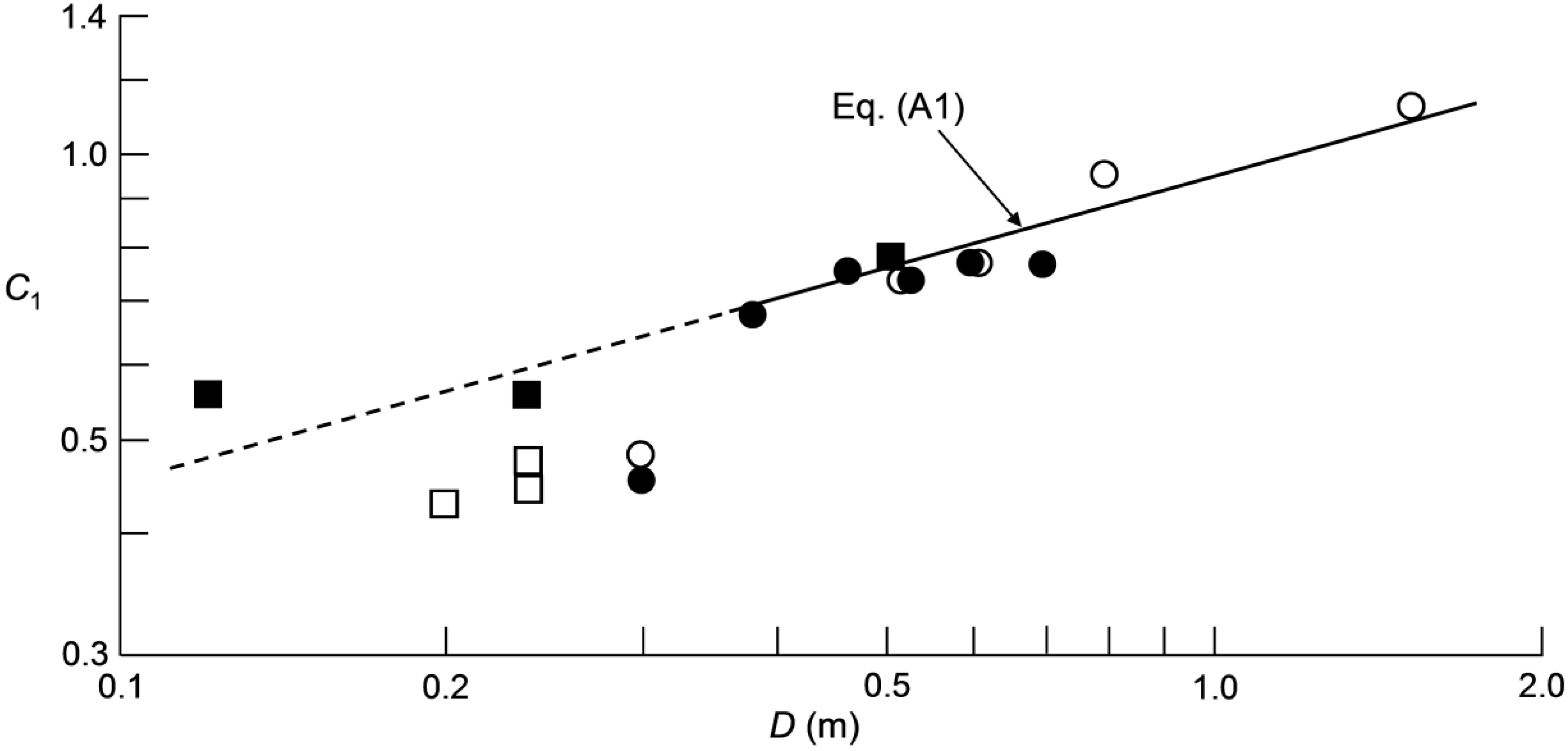
Appendix: Scale Effect on C1 and Its Consequence for Stirred-Tank Scale-up
Wichterle [27] showed a C1 versus D diagram on which experimental data from several different sources were comparatively plotted, noting that the diagram was reproduced from an unpublished Ph.D. thesis submitted by E. Odehnal to the Research Institute for Macromolecular Chemistry, Brno, Czech Republic, in 1979. All the data points plotted there are reproduced in Figure A1. (The two curves so drawn in the original diagram as to be fit to the data points from two sources are omitted in Figure A1.) These data points show a tendency of C1 increasing with an increase in D. However, such a dependence of C1 on D is apparently inconsistent with our established idea that forced-convection heat transfer in any single-phase flow system can be formulated in terms of only three dimensionless moduli—the Nusselt, the Reynolds and the Prandtl numbers—without using any other variable. Thus, the involvement of D as an additional variable in correlating the heat transfer between the stirred liquid and the tank wall needs a physical reasoning. Wichterle [27] suggested the effect of surface aeration induced by strong stirring; i.e., the effect of such aeration might have been more significant with smaller tanks, thereby more significantly reducing the heat transfer in smaller tanks. This interpretation of the experimentally observed dependence of C1 on D is an as-yet unconfirmed hypothesis. Moreover, it is unclear how such a C1 versus D relation changes, or does not change, when a hydrate-forming gas is bubbled in the liquid phase. This is the reason why we simply assumed C1 to be constant in the formulation described in Section 3.1. In this Appendix, however, we briefly describe how the formulation in Section 3.1 should change, if such a D dependence of C1 that the experimental data indicate actually prevails in stirred-tank-type hydrate-forming reactors.
We note in Figure A1 that, in the D range exceeding ~0.36 m, data points from three different sources are well correlated by a simple formula:
where the constant a is approximated by 0.93 m−1/3. In the lower D range, the data points from different sources exhibit different (presumably, apparatus-dependent) D dependences and cannot be simply correlated. Thus, the formulation given below is limited for the D range above ~0.36 m.
Substituting Equation (A1) into Equation (3), we have
In the present formulation, Equation (A2) substitutes for Equation (3) used in Section 3.1. In case I (size-independent liquid-to-wall thermal conductance per unit volume), the expressions for N and are altered from Equations (9) and (10) into the following forms:
Note that the dependences of N and on D are slightly moderated by using Equation (A2) instead of Equation (3). In case II (size-independent gas–liquid flow pattern inside tanks), the expressions for h are altered from Equations (15) and (18) as follows:
The expressions for N and undergo no change from Equations (14), (16), (17) and (19).
Figure A1.
Comparison between the experimental C1 versus D data and Equation (A1) in which the lead constant a is adjusted at 0.93 m−1/3. The data points were reproduced from Figure 4 in [27]. As for the four original data sources (marked by the four different symbols in this diagram), consult the caption for Figure 4 in [27].

Nomenclature
Latin letters
| A | inside surface area of a tube relevant to heat transfer, m2 |
| a | constant defined in Equation (A1), m−1/3 |
| C1 | empirical factor defined in Equation (1), dimensionless |
| C2 | constant given by Equation (4), J·K−1·m−7/3·s−1/3 |
| C3 | empirical factor defined in Equation (12), dimensionless |
| cp, g | specific heat at constant pressure of hydrate-forming gas (evaluated at bulk temperature), J kg−1 K −1 |
| cp, l | specific heat at constant pressure of liquid (evaluated at bulk temperature), J·kg−1·K−1 |
| D | inside diameter of stirred-tank or tubular reactor, m |
| d | impeller diameter, m |
, impeller-to-tank diameter ratio, dimensionless | |
| f | friction factor for water flow through a tube, dimensionless |
| Fl | , Flow number for buoyant gas flow versus stirrer-driven flow, dimensionless |
| Fr | , Froude number for stirrer-driven flow, dimensionless |
| g | acceleration due to gravity, m2·s −1 |
| H | depth of liquid pool in a stirred-tank reactor, m |
, height-to-diameter ratio of liquid pool in a stirred-tank reactor, dimensionless | |
| h | convection coefficient for heat transfer from aqueous phase to reactor wall, W·m−2·K−1 |
| J | factor of magnification in water mass flow rate, , accompanying reactor scale-up, dimensionless |
| kl | thermal conductivity of liquid (evaluated at bulk temperature), W·m−1·K−1 |
| L | axial tube length relevant to heat transfer, m |
mass flow rate of hydrate-forming gas through a tube, kg·s−1 | |
mass flow rate of liquid through a tube, kg·s−1 | |
| N | rotational speed (revolutions per second) of stirrer shaft, s−1 |
| Nt | number of tubes arranged in parallel in a tubular reactor, dimensionless |
| NuD | , Nusselt number for heat transfer from aqueous phase to reactor wall, dimensionless |
| Po | , Power number for stirring liquid by an impeller or impellers, dimensionless |
mean Po value over an estimated Red range relevant to the operation of scaled-up reactor | |
| Prl | , Prandtl number of liquid (evaluated at bulk temperature), dimensionless |
| ReD | , Reynolds number for liquid flow through a tube, dimensionless |
| Red | , Reynolds number for rotational liquid flow induced by a stirrer, dimensionless |
| U | overall coefficient of heat transfer across tube wall (based on inside tube-surface area), W·m−2·K−1 |
| uav | average axial velocity of liquid flowing through a tube, m·s−1 |
| ug | , superficial gas velocity in a stirred-tank reactor, m·s−1 |
volumetric flow rate of hydrate-forming gas, m3·s−1 | |
, volumetric gas flow rate per unit liquid volume in a stirred-tank reactor, s−1 | |
| Vil | , bulk-to-wall viscosity ratio of liquid, dimensionless |
power required for driving a stirrer or for pumping liquid through a tube against the friction working on the tube wall over axial length L, W | |
| Δp | pressure drop along the liquid flow through a tube over its axial length L, Pa |
Acronyms
| NTU | number of transfer units defined by Equation (20), dimensionless |
| STC | specific thermal conductance defined by Equation (7), W·m−3·K−1 |
Greek letters
| μl | dynamic viscosity of liquid (evaluated at bulk temperature), Pa·s |
| μls | dynamic viscosity of liquid (evaluated at reactor-wall temperature), Pa·s |
| νl | kinematic viscosity of liquid (evaluated at bulk temperature), m2·s−1 |
| ρl | mass density of liquid (evaluated at bulk temperature), kg·m−3 |
| τg | , superficial gas residence time in the liquid phase inside a stirred-tank reactor, s |
Conflicts of Interest
The author declares no conflict of interest.
References
- Sloan, E.D., Jr.; Koh, C.A. Clathrate Hydrates of Natural Gases, 3rd ed.; CRC Press: Boca Raton, FL, USA, 2008; Section 1.2.7. [Google Scholar]
- Barduhn, A.J. Desalination by crystallization processes. Chem. Eng. Prog. 1967, 63, 98–103. [Google Scholar]
- Ida, H.; Kohda, K. Highly efficient natural gas hydrate production technology. JFE Giho 2004, 6, 76–80. (In Japanese) [Google Scholar]
- Iwasaki, T.; Katoh, Y.; Nagamori, S.; Takahashi, S.; Oya, N. Continuous natural gas hydrate pellet production (NGHP) by process development unit (PDU). In Proceedings of the 5th International Conference on Gas Hydrates, Trondheim, Norway, 12–16 June 2005. Paper No. 4003.
- Horiguchi, K.; Watanabe, S.; Moriya, H.; Nakai, S.; Yoshimitsu, A.; Taoda, A. Completion of natural gas hydrate (NGH) overland transportation demonstration project. In Proceedings of the 7th International Conference on Gas Hydrates, Edinburgh, Scotland, UK, 17–21 July 2011. Paper No. P5.053.
- Nauman, E.B. Chemical Reactor Design, Optimization, and Scaleup, 2nd ed.; Wiley: Hoboken, NJ, USA, 2008. [Google Scholar]
- Mori, Y.H. Recent advances in hydrate-based technologies for natural gas storage—A review. J. Chem. Ind. Eng. 2003, 54, 1–17. [Google Scholar]
- Gudmundsson, J.S.; Parlaktuna, M.; Levik, O.I.; Andersson, V. Laboratory for continuous production of natural gas hydrates. Ann. N.Y. Acad. Sci. 2000, 912, 851–858. [Google Scholar] [CrossRef]
- Hutchinson, A.J.L. System for Forming and Storing Hydrocarbon Hydrates. U.S. Patent US2356407, 22 August 1944. [Google Scholar]
- Rogers, R.E.; Yevi, C.Y.; Swalm, M. Hydrates for storage of natural gas. In Proceedings of the 2nd International Conference on Natural Gas Hydrates, Toulouse, France, 2–6 June 1996; pp. 423–429.
- Ohmura, R.; Kashiwazaki, S.; Shiota, S.; Mori, Y.H. Structure-I and structure-H hydrate formation using water spraying. Energy Fuels 2002, 16, 1141–1147. [Google Scholar] [CrossRef]
- Yoshikawa, K.; Kondo, Y.; Kimura, T.; Fujimoto, T. Production Method for Hydrate and Device for Processing the Same. U.S. Patent US6653516 B1, 25 November 2003. [Google Scholar]
- Brinchi, L.; Castellani, B.; Rossi, F.; Cotana, F.; Morini, E.; Nicolini, A.; Filipponi, M. Experimental investigations on scaled-up methane hydrate production with surfactant promotion: Energy considerations. J. Pet. Sci. Technol. 2014, 120, 187–193. [Google Scholar]
- Kutergin, O.B.; Mel’nikov, V.P.; Nesterov, A.N. Surfactant effect on the mechanism and kinetics of gas hydrate formation. Dokl. Akad. Nauk 1992, 323, 549–553. (In Russian) [Google Scholar]
- Okutani, K.; Kuwabara, Y.; Mori, Y.H. Surfactant effects on hydrate formation in an unstirred gas/liquid system: An experimental study using methane and sodium alkyl sulfates. Chem. Eng. Sci. 2008, 63, 183–194. [Google Scholar] [CrossRef]
- Ando, N.; Kodama, T.; Kondo, W.; Mori, Y.H. Clathrate hydrate formation from a methane + ethane + propane mixture in an unstirred surfactant-containing system. Energy Fuels 2012, 26, 1798–1804. [Google Scholar] [CrossRef]
- Mel’nikov, V.P.; Nesterov, A.N.; Feklistov, V.V. Device for gas hydrate formation. Russian Patent RU2166348 C1, 05 October 2001. [Google Scholar]
- Watanabe, K.; Imai, S.; Mori, Y.H. Surfactant effects on hydrate formation in an unstirred gas/liquid system: An experimental study using HFC-32 and sodium dodecyl sulfate. Chem. Eng. Sci. 2005, 60, 4846–4857. [Google Scholar] [CrossRef]
- Seo, Y.-T.; Moudrakovski, I.L.; Ripmeester, J.A.; Lee, J.-W.; Lee, H. Efficient recovery of CO2 from flue gas by clathrate hydrate formation in porous silica gels. Environ. Sci. Technol. 2005, 39, 2315–2319. [Google Scholar] [CrossRef] [PubMed] [Green Version]
- Linga, P.; Daraboina, N.; Ripmeester, J.A.; Englezos, P. Enhanced rate of gas hydrate formation in a fixed bed column filled with sand compared to a stirred vessel. Chem. Eng. Sci. 2012, 68, 617–623. [Google Scholar] [CrossRef]
- Babu, P.; Kumar, R.; Linga, P. A new porous material to enhance the kinetics of clathrate process: Application to precombustion carbon dioxide capture. Environ. Sci. Technol. 2013, 47, 13191–13198. [Google Scholar] [CrossRef] [PubMed]
- Matsuda, S.; Tsuda, H.; Mori, Y.H. Hydrate formation using water spraying onto a cooled solid surface in a guest gas. AIChE J. 2006, 52, 2978–2987. [Google Scholar] [CrossRef]
- Murakami, T.; Kuritsuka, H.; Fujii, H.; Mori, Y.H. Forming a structure-H hydrate using water and methylcyclohexane jets impinging on each other in a methane atmosphere. Energy Fuels 2009, 23, 1619–1625. [Google Scholar] [CrossRef]
- Fujita, S.; Watanabe, K.; Mori, Y.H. Clathrate-hydrate formation by water spraying onto a porous metal plate exuding a hydrophobic liquid coolant. AIChE J. 2009, 55, 1056–1064, Errata: AIChE J. 2009, 55, 1916. [Google Scholar]
- Yamamura, K.; Fukuzaki, J.; Mori, Y.H. Clathrate hydrate formation using liquid jets impinging on each other: An observational study using paired water jets or water and methylcyclohexane jets. Chem. Eng. Sci. 2011, 66, 1844–1858. [Google Scholar] [CrossRef]
- Linga, P.; Kumar, R.; Lee, J.D.; Ripmeester, J.; Englezos, P. A new apparatus to enhance the rate of gas hydrate formation: Application to capture of carbon dioxide. Int. J. Greenh. Gas Control 2010, 4, 630–637. [Google Scholar] [CrossRef]
- Wichterle, K. Heat transfer in agitated vessels. Chem. Eng. Sci. 1994, 9, 1480–1483. [Google Scholar] [CrossRef]
- Rushton, J.H.; Costich, E.W.; Everett, H.J. Power characteristics of mixing impellers. 1. Chem. Eng. Progr. 1950, 46, 395–404. [Google Scholar]
- Rushton, J.H.; Costich, E.W.; Everett, H.J. Power characteristics of mixing impellers. 2. Chem. Eng. Progr. 1950, 46, 467–476. [Google Scholar]
- Mueller, S.G.; Dudukovic, M.P. Gas holdup in gas–liquid stirred tanks. Ind. Eng. Chem. Res. 2010, 49, 10744–10750. [Google Scholar] [CrossRef]
- Lee, B.W.; Dudukovic, M.P. Determination of flow regime and gas holdup in gas–liquid stirred tanks. Chem. Eng. Sci. 2014, 109, 264–275. [Google Scholar] [CrossRef]
- Dorstewitz, F.; Mews, D. The influence of heat transfer on the formation of hydrate layers in pipes. Int. J. Heat Mass Transf. 1994, 37, 2131–2137. [Google Scholar] [CrossRef]
- Yang, D.; Le, L.A.; Martinez, R.J.; Currier, R.P.; Spencer, D.F.; Depper, G. Heat transfer during CO2 hydrate formation in a continuous flow reactor. Energy Fuels 2008, 22, 2649–2659. [Google Scholar] [CrossRef]
- Incropera, F.P.; DeWitt, D.P.; Bergman, T.L.; Lavine, A.S. Fundamentals of Heat and Mass Transfer, 6th ed.; Wiley: Hoboken, NJ, USA, 2011; Section 8.1.4. [Google Scholar]
- Taitel, Y.; Dukler, A.E. A model for predicting flow regime transitions in horizontal and near horizontal gas–liquid flow. AIChE J. 1976, 22, 47–55. [Google Scholar] [CrossRef]
© 2015 by the authors; licensee MDPI, Basel, Switzerland. This article is an open access article distributed under the terms and conditions of the Creative Commons Attribution license (http://creativecommons.org/licenses/by/4.0/).
Share and Cite
MDPI and ACS Style
Mori, Y.H. On the Scale-up of Gas-Hydrate-Forming Reactors: The Case of Gas-Dispersion-Type Reactors. Energies 2015, 8, 1317-1335. https://doi.org/10.3390/en8021317
AMA Style
Mori YH. On the Scale-up of Gas-Hydrate-Forming Reactors: The Case of Gas-Dispersion-Type Reactors. Energies. 2015; 8(2):1317-1335. https://doi.org/10.3390/en8021317
Chicago/Turabian StyleMori, Yasuhiko H. 2015. "On the Scale-up of Gas-Hydrate-Forming Reactors: The Case of Gas-Dispersion-Type Reactors" Energies 8, no. 2: 1317-1335. https://doi.org/10.3390/en8021317