Article

Research on and Design of a Self-Propelled Nozzle for the Tree-Type Drilling Technique in Underground Coal Mines

1
State Key Laboratory of Coal Mine Disaster Dynamics and Control, Chongqing University, Chongqing 400044, China
2
National & Local Joint Engineering Laboratory of Gas Drainage in Complex Coal Seam, Chongqing University, Chongqing 400044, China
*
Authors to whom correspondence should be addressed.
Energies 2015, 8(12), 14260-14271; https://doi.org/10.3390/en81212426
Submission received: 25 October 2015 / Revised: 14 December 2015 / Accepted: 15 December 2015 / Published: 17 December 2015

Abstract

:
Due to the increasing depths of coal mines and the low permeability of some coal seams, conventional methods of gas drainage in underground mines are facing many problems. To improve gas extraction, a new technique using water jets to drill tree-type boreholes in coal seams is proposed. A self-propelled water-jet drilling nozzle was designed to drill these boreholes. The configuration of the self-propelled nozzle was optimized by conducting drilling experiments and self-propelling force measurements. Experimental results show that the optimal self-propelled nozzle has a forward orifice axial angle at 25°, a radial angle at 90°, a center distance of 1.5 mm, and backward pointing orifices with an axial angle of 25°. The self-propelling force generated by the jets of the nozzle with 30 MPa pump pressure can reach 29.8 N, enough to pull the hose and the nozzle forward without any external forces. The nozzle can drill at speeds up to 41.5 m/h with pump pressures at 30 MPa. The radial angles of the forward orifices improve the rock breaking performance of the nozzle and, with the correct angle, the rock breaking area of the orifices overlap to produce a connecting hole. The diameter of boreholes drilled by this nozzle can reach 35.2 mm. The nozzle design can be used as the basis for designing other self-propelled nozzles. The drilling experiments demonstrate the feasibility of using the tree-type drilling technique in underground mines.

1. Introduction

Coalbed methane (CBM) has become a topic of great interest worldwide in recent years. CBM is a kind of unconventional clean energy. The Chinese government attaches great importance to CBM exploitation because CBM provides comprehensive benefits. Its use can increase energy supplies, reduce greenhouse gas emissions, and its extraction can help prevent gas disasters in underground coal mines [1,2,3]. The most common methods of CBM exploitation are surface well drilling and underground gas drainage. The surface well drilling method has been widely used in many developed countries, such as the USA, Canada, and Australia. However, the main method in China is underground gas drainage in order to recover gas and coal simultaneously [4,5,6,7].
The primary technology for CBM drainage in underground mines is to drill gas drainage boreholes into the coal seams [8,9]. These boreholes can be drilled vertically from the floor roadways or horizontally in the coal seams. The horizontal boreholes are usually drilled from roadways developed within the coal seam. This means that the roadway must be tunneled before the coal and gas are extracted, a dangerous operation that, in adverse circumstances, is likely to cause coal and gas outbursts [10,11]. The surface drilling technique, however, also faces some serious problems. These problems include: (1) With increasing mine depth, coal seam permeability decreases and the gas extraction rate becomes very low [12,13]; (2) The volume of coal from which the gas can be extracted by a single borehole is small; (3) A very large number of boreholes are required to ensure that no blank areas (volumes from which the gas cannot be drained) remain in the coal seams; (4) Long range boreholes, which normally go through the floor rock seams, take a very long time to drill; (5) In most cases, coal seam roof and floor rocks are very hard, making drilling difficult, and drilling efficiency is very low; (6) Even after the surface boreholes are completed, extracting the expected quantity of gas takes a long time [14].
To expand the volume of coal from which the gas can be extracted using a single borehole and improve gas drainage efficiency, this paper proposes a new technique for gas drainage by using tree-type boreholes in coal seams. Figure 1 shows a schematic of tree-type drilling. The drilling procedures are: (1) Drilling a main borehole into the coal seam from the floor roadway of an underground coal mine. This is the same as drilling a conventional drainage borehole; (2) Pushing a whipstock into position through the main borehole; (3) Putting a self-propelled nozzle into the orifice of the main borehole; this nozzle moves forward into the whipstock under its own self-propelled force; (4) Drilling a sub-borehole perpendicular to the main borehole with the self-propelled nozzle using a high-pressure water jet; (5) Changing the direction of the whipstock and repeating step 4; (6) Conducting step 5 multiple times to form a tree-type array of holes.
Figure 1. Schematic diagram of drilling to make tree-type boreholes in a coal seam.
Energies 08 12426 g001
This technique can create a large number of holes in a coal seam in a relatively short time and the necessary equipment is simpler than that needed for conventional drilling. Using water jets to drill can reduce dust emissions and thus improve working conditions in the mine. The diameter of the sub-borehole can be 30–50 mm and the sub-borehole lengths can reach 10–20 m. The tree-type drilling technique can improve gas drainage efficiency greatly by expanding the volume of coal that can be drained and eliminating the blank areas. However, this technique also faces some challenges. These include design and development of all the equipment needed, choosing the right drilling parameters, and determining the optimal hole arrangements for maximum drainage efficiency.
The equipment needed to drill these tree-type boreholes includes a high-pressure pump, a winch, the whipstock, high-pressure hose, and the self-propelled nozzle. Without doubt, the nozzle is the key to success for tree-type drilling. The nozzle must be able to break the rock (coal) to form a sub-borehole and self-generate enough force to both move forward through the rock and pull the hose behind it.
This paper focuses on the design of the nozzle. The structure of the nozzle was studied in order to obtain a nozzle that could self-propel forcefully. For this purpose experiments to find the optimal nozzle configuration that would break rock efficiently while maintaining its self-propelled ability were conducted.

2. Preliminary Design

The self-propelled nozzle is a multi-orifice nozzle with orifices that point both forwards and backwards (Figure 2). The forward pointing orifices direct high-pressure water jets to break the rock (coal) to form the sub-boreholes while the backward pointing orifices eject jets backwards to generate the self-propelling force and to expand the sub-borehole. To be able to manufacture the best nozzle possible, it is necessary to study the rock-breaking properties and the self-propelling ability of the nozzle.
The forward orifices of conventional multi-orifice nozzles are arranged with an axial angle that defines the area of coal that is broken. During drilling, the standoff distance (the distance from forward orifice to the target rock) changes continuously. The axial angle orifice arrangement will cause the area of rock broken by each individual orifice to be separate when the standoff distance is relatively large. This makes breaking the rock in the central zone of target difficult and the result is low drilling efficiency.
This paper proposes adding radial angles to the forward orifices, as shown in Figure 2. Using a radial angle arrangement, the rock breaking area for every orifice will overlap whether the standoff distance is long or short. When the radial angle is 90°, the breaking areas overlap enough to break the central zone of the target rock and form a connecting hole as shown in Figure 3.
Figure 2. Structural diagram of the self-propelled nozzle.
Energies 08 12426 g002
Figure 3. Breaking position changes with standoff distance.
Energies 08 12426 g003
The parameters that must be specified to define the layout of the new multi-orifice nozzle include the diameter and the number of forward and backward orifices, the axial and radial angles of forward orifices, and the radial angle of backward orifices. The diameter and the number of orifices can be obtained by theoretical calculations. The optimal axial and radial angles will be determined by experiments.
Most coal mines in China have gas drainage boreholes under 133 mm in diameter [15]. Because the nozzle and the high-pressure hose have to make turns in the main borehole and the turning radius is limited, the hose should be pliable. The hose selected has an outer diameter of 12.7 mm and of inner diameter is 6.35 mm. Its pressure loss, Δp, can be calculated by Equation (1) [16,17]:
Δ p = 59.7 q 2 D 5 Re 0.25
where q is the volume flow rate in L/min, D is the inner diameter of the high-pressure hose in mm, and Re is the Reynolds number (Re = 11,165 q/D).
From Equation (1), it can be seen that the Δp increases quickly with an increase in q. When q is 40 L/min, Δp is 0.63 MPa/m. When q reaches 50 L/min, Δp is 0.94 MPa/m. In order to keep the pressure loss reasonably low, 40 L/min was chosen as the design flow rate.
The volume flow rate can be expressed as:
q = 60 μ A t 2 p ρ
where μ is the flow coefficient of the orifice, At is the total area of the nozzle orifices in mm2, p is the inlet pressure in MPa, and ρ is the fluid density in kg/m3.
In order to facilitate the machine processing, the orifices in the nozzle are designed to be cylindrical. The flow coefficient for a cylindrical orifice can be valued as 0.82 [18]. The expression of At is:
A t = n π d 2 4
where n is the number of orifices and d is the orifice diameter in mm.
Thus, the Equation (2) can be expressed as:
d = ( ρ q 2 450 μ 2 n 2 π 2 p ) 0.25
The nozzle has three forward orifices and eight backward facing orifices, so n is 11. Most coal mines in China use model BZW200/31.5 pumps [19] that have a maximum rated capacity of 200 L/min at their maximum rated pressure of 31.5 MPa. Therefore, the inlet pressure for these calculations is taken to be 30 MPa. From Equation (4), the orifice diameter d is 0.62 mm. Due to constraints of actually machining the metal parts, the design value of the orifice diameters is set at 0.6 mm.
As shown in Figure 2, the configuration of the forward orifices is defined by the axial angle, α, the radial angle, β, and the center distance, l. These parameters will govern the three-dimensional velocity distribution (axial, radial and tangential) of the jets and determine the rock breaking efficiency of the nozzle. The orientation of the backward orifices is defined only by the axial angle, γ, and γ influences the self-propelling force produced by the jets.

3. Drilling Speed Tests

Drilling speed tests were conducted to study the effect of different configurations of the forward orifices on the rock breaking efficiency.

3.1. Test Apparatus and Method

Figure 4 is a schematic diagram of the drilling speed test experimental system. Fluid pumped by the high-pressure pump flows through a pressure control valve and then some of fluid flows into the jet generator to form the jets that break the rock. The main components and relevant performance parameters for the experimental system are listed below:
  • The high-pressure pump; rated pressure 32.5 MPa, rated flow rate 200 L/min.
  • The jet generator; main components include the hose connector, the pressure gauge, high-pressure hose, and the nozzle connector.
  • The drilling console mounted on tracks. There is a removable steel bar for fixing the nozzle to the steel pipe connected to the drilling console. When measuring the self-drilling speed, the bar is removed freeing the nozzle to move forward. When conducting the rock breaking tests and studying the pattern of broken holes, the bar is replaced to fix the nozzle to the drilling console so that the two will move together. The rate at which the drilling console can move is controlled by an electric motor and ranges from 0.01 to 100 mm/s.
  • The nozzle. Using the control variable method to design experiments, the influence law of each forward orifice configuration on rock breaking efficiency of the nozzle was studied. Thirteen different self-propelled nozzles were designed and machined for testing. The nozzles, shown in Figure 5, all have the same backward orifices axial angle (25°). The specifications for the forward orifices are shown in Table 1. According to previous research, the optimal axial angle for a nozzle orifice is about 20° for rock breaking [20]. Therefore, the values of axial angle in the nozzles used for this study are around 20° and 5° as a research level considering machining limits. The values of radial angle cover the whole range from 0° to 90°. The values of center distance are limited by the diameter of the nozzle, so the maximum is 1.8 mm (±0.1 mm as a level also due to machining limits).
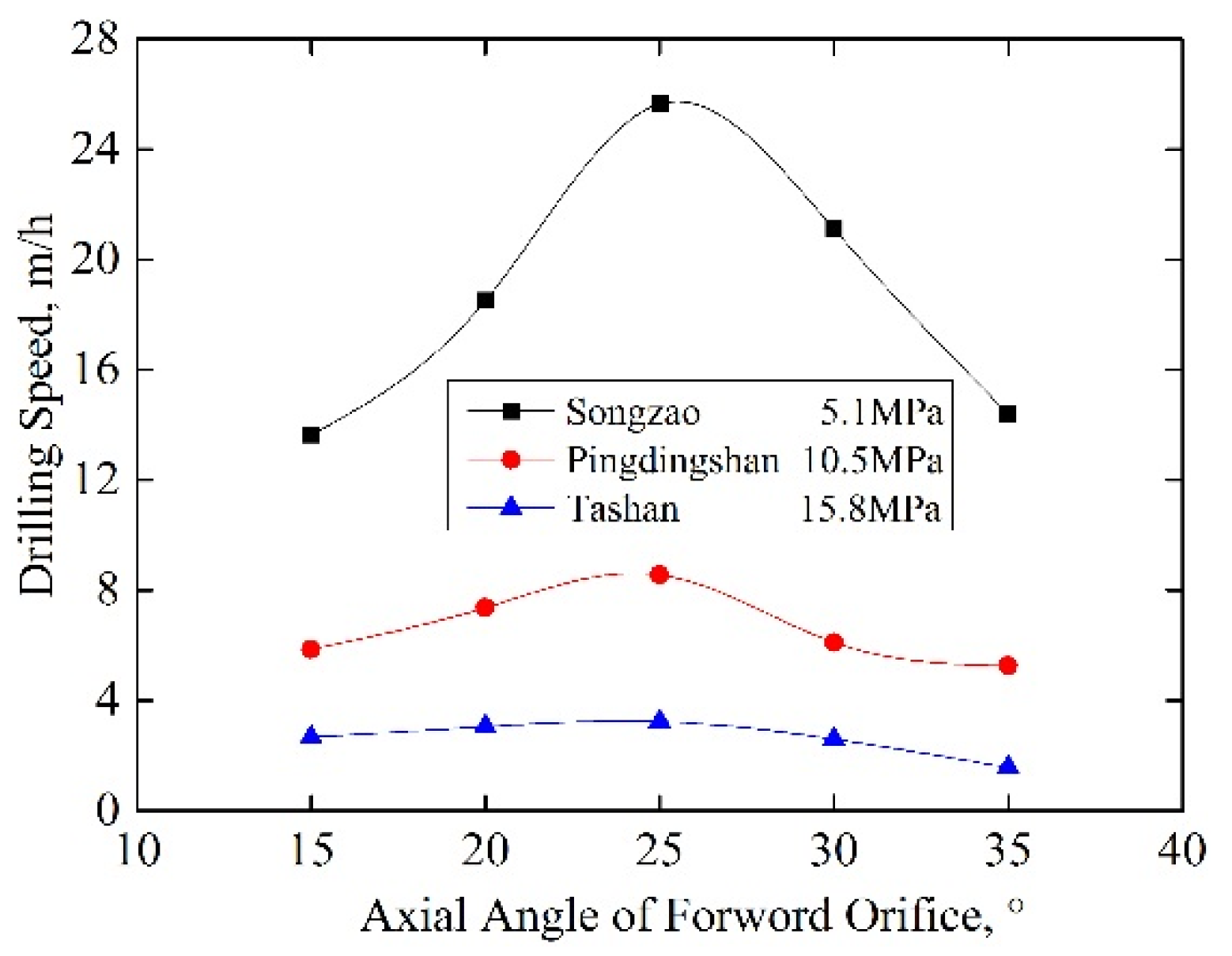
  • Experimental coal sample. Coals from different mines in different regions can have very different physical properties. In order to test drilling in different kinds of coal and determine if the technique is broadly applicable, large blocks of coal were collected from three coal mines for drilling tests. The mines were the Songzao mine in southwest China, the Pingdingshan mine in central China, and the Tashan mine in northwest China. The coal ranks are from high volatile bituminous to anthracite and their hardnesses range from low to high. The experimental coal block sample from the Pingdingshan mine is shown in Figure 6.
Standard cores were drilled from the coal blocks for mechanical testing. Following International Society for Rock Mechanics (ISRM) standard testing procedures, the 50 mm diameter by 100 mm long cores were dried for 24 h in an oven. The uniaxial compressive strength of the cores were measured by an MTS-815 Universal Testing Machine (MTS Systems Corp., Eden Prairie, MN, USA) [21]. The average strength values for the three samples were 5.1, 10.5 and 15.8 MPa.
Figure 4. Device connection schematic for the self-drilling speed testing system.
Energies 08 12426 g004
Figure 5. Self-propelled nozzles with different forward orifices.
Energies 08 12426 g005
Table 1. Axial and radial angles and center distance offsets of the forward orifices for thirteen self-propelled nozzles.
NumberForward Orifice Structure Parameters
Axial Angle α/°Radial Angle β/°Center Distance l/mm
1#1501.5
2#2001.5
3#2501.5
4#3001.5
5#3501.5
6#25251.5
7#25451.5
8#25651.5
9#25901.5
10#25901.4
11#25901.6
12#25901.7
13#25901.8
Figure 6. Coal sample from the Pingdingshan mine used for drilling tests.
Energies 08 12426 g006
All the drilling speed tests were carried out with the same fixed drilling time and fixed jet impact pressure. The drilling test samples are the raw coal blocks from fields, and they are fixed on an open platform during the tests. Drilling time was 90 s and jet impact pressure was 30 MPa. The drilling speed was calculated simply by measuring the depth of the hole drilled and dividing by 90 s.

3.2. Experimental Results and Discussion

3.2.1. The Effect of the Forward Orifice Axial Angle on Self-Drilling Speeds

The axial angle of the forward orifice determines the jet incidence angle, that is, the angle between the jet axis and the plane normal to the rock surface. When jet fluid hits the rock from different directions, the stress distribution within the rock changes; the axial angle of the forward orifice is an important factor for drilling.
As shown in Figure 7, the range of axial angles is 15°–35°. Under the same experimental conditions, the self-drilling speed first increases and then decreases with the increase of axial angle. Drilling speed is highest when the axial angle of the forward orifice is 25°. When the axial angle is less the 25°, the backflow caused by the forward jets on the rock surface is strong and this hinders the follow-up jets and causes the self-drilling speed to decreasing. When the axial angle is around 25°–35°, the jet impact pressure on the sample decreases gradually with the increase axial angle so the self-drilling speed also gradually decreases. Using the self-drilling speed as the evaluation criterion, the optimal axial angle for forward orifice as determined by these experiments is 25°.
Figure 7. Graph showing the relationship between self-drilling speed and forward orifice axial angle. Strength of coal samples: 5.1, 10.5 and 15.8 MPa.
Energies 08 12426 g007

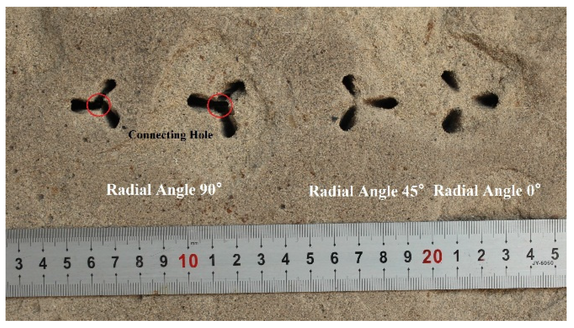
3.2.2. The Effect of the Forward Orifice Radial Angle on Self-Drilling Speeds

During self-drilling, the radial angle of forward orifice determines the direction of the jets and that determines the pattern of the holes broken. The pattern that will make the holes overlap more will achieve higher drilling speeds. As shown in Figure 8, the drilling speed increases with the increase of radial angle.
Rock breaking tests were conducted to study the patterns of broken holes using different nozzles with different radial angles. Sandstone was chosen for the target because it is easier to observe the pattern of broken holes in sandstone than in coal. The uniaxial compressive strength of the sandstone sample was 27.4 MPa. The initial standoff distance was 5 mm and the drilling console + nozzle was advanced at 0.1 mm/s. The hole patterns created by four different nozzles are shown in Figure 9.
Figure 8. Graph showing the relationship between self-drilling speed and forward orifice radial angle. Strength of coal samples: 5.1, 10.5 and 15.8 MPa.
Energies 08 12426 g008
Figure 9. Pattern of holes broken in sandstone with different forward orifice radial angles. Note that the nozzles with the 90° radial angle orifices broke out the center zone of the target (red circles) whereas the 45° and 0° radial angle nozzles did not.
Energies 08 12426 g009
When the radial angle of the forward orifices is 90°, the areas of rock broken by the orifices overlap and form a connecting hole. This pattern effectively combines the jet impact of the three forward orifices to break the central zone and is the reason that this 90° radial angle arrangement results in the highest self-drilling speed.

3.2.3. The Effect of Forward Orifice Center Distance on Self-Drilling Speeds

The center distance of the forward orifices determines how much the jets diverge and also influences how much the jets and the holes they produce overlap.
As listed in Table 1, the center distances for the nozzle forward orifices range from 1.4 to 1.8 mm. Figure 10 shows self-drilling speed plotted against the center distance for five tests with nozzles all having forward orifice radial angles of 90°. Under the same experimental conditions, the self-drilling speed first increases and then decreases with the increase of center distance. When the center distance is 1.5 mm, the self-drilling speed is at its maximum. When the center distance is 1.4 mm, the decrease in drilling speed is because the arrangement of the three orifices is so centralized that the total area of rock broken is too small. The nozzle does not fit through the hole even though holes broken by the jets overlap and break out the center zone. When the center distance is more than 1.5 mm, the overlap area of the jets decreases as the center distance increases, hindering the self-drilling. For these experiments, the optimal center distance for the forward orifice is 1.5 mm.
Figure 10. Graph showing the relationship between self-drilling speed and forward orifice center distance. Strength of coal samples: 5.1, 10.5 and 15.8 MPa.
Energies 08 12426 g010

4. Self-Propelling Force Measurement

Tests were also conducted to measure the self-propelling force that the nozzles could generate. The amount of force that a nozzle can produce is a function of fluid pressure and the nozzles backward orifices axial angle, so total self-propelling force tests were conducted using different backward orifice configurations at different pressures.

4.1. Test Apparatus and Method

These experiments used an accurate measuring system for small forces. A schematic of the equipment is shown in Figure 11. The system includes:
  • The high-pressure pump and jet generator. The performance parameters are the same as those described in Section 3.1.
  • A through-hole load cell. A load cell, model number LC8200-625-50 (from Omega Engineering Company, Stamford, CT, USA) was used to measure the forces. The load cell has a ~5 cm (2-inch) outer diameter and ~16 mm (0.625-inch) inner diameter and can measure forces in the 0–222 N range accurately.
  • A glass pipe. The glass pipe was used to simulate a gas drainage borehole in a coal seam. The pipe’s inner diameter was 50 mm.
  • Self-propelled nozzles. To analyze the total self-propelling force of the nozzle, five self-propelled nozzles with different backward orifice structures were machined. The nozzles are shown in Figure 12. These five nozzles all have the same forward orifice configuration (axial angle 25°; radial angle 90°; center distance 1.5 mm). The specifications for the backward orifices on the nozzles are shown in Table 2.
Total self-propelling force measurement was carried out at three different pump pressures, 10, 20 and 30 MPa.
Figure 11. Device connection schematic for a self-propelling force measurement system.
Energies 08 12426 g011
Figure 12. Self-propelled nozzles with different backward orifices axial angles.
Energies 08 12426 g012
Table 2. Backward orifice axial angles for five self-propelled nozzles used for self-propelling force measurements.
NumberBackward Orifice Axial Angle/°
1#10
2#15
3#20
4#25
5#30

4.2. Experimental Results and Discussion

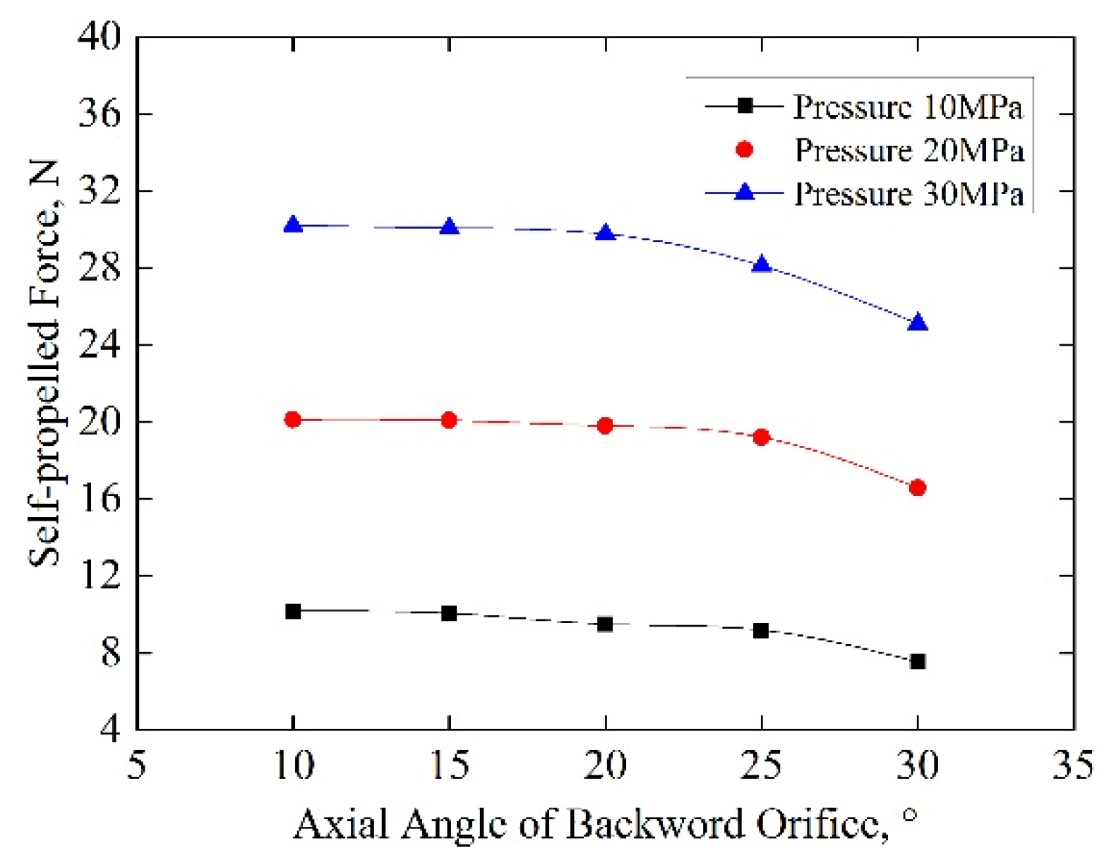
4.2.1. The Effect of Backward Orifice Axial Angle on Total Self-Propelling Force

Figure 13 shows the relationship between the self-propelling force and the axial angle of the backward orifices. When the axial angle is under 25°, the self-propelling force is large. For our experiment, it is 29.82 N for a 25° axial angle with 30 MPa pump pressure. The self-propelling force is acting against the frictional resistance drilling in coal seams and the resistance produced in the whipstock. The laboratory measured friction coefficient between the hose and the hole wall in coal seams is 0.25–0.35. The hose used in the tests weighs 0.2 kg per meter, so the force exerted by gravity is about 20 N when the drilling length is 10 m. The calculated value of frictional resistance is about 7 N. The resistance produced in the whipstock can be measured by the load cell and the value is approximately 10 N. The total force retarding the nozzle advance is 17 N and smaller than the nozzle propelling force. Therefore, the self-propelling force is enough to pull the hose forward without any external forces being provided. When the axial angle is more than 25°, the self-propelling force decreases significantly. When the axial angle of the backward orifice increases, the component of jet velocity parallel to the axis of the nozzle decreases and the self-propelling force decreases as well.
Figure 13. Graph showing the relationship between the self-propelling force and the axial angle of the backward orifices.
Energies 08 12426 g013

4.2.2. The Effect of the Backward Orifice Axial Angle on the Diameter of the Self-Drilled Borehole

Self-drilling tests using these five nozzles were also conducted. The relationship between the diameter of the self-drilled borehole and the axial angle of backward orifices is shown in Figure 14. Borehole diameter increases as the axial angle of the backward orifices increases. Taking self-propelling force and self-drilling borehole diameter as evaluation criteria, the optimal axial angle for backward orifices is 25°. With the orifices at 25°, the self-propelling force is close to its maximum and the diameter of the borehole is sufficiently large to meet the requirements of a working mine.
Figure 14. Graph showing the relationship between borehole diameter and backward orifice axial angle. Strength of coal samples: 5.1, 10.5 and 15.8 MPa.
Energies 08 12426 g014

5. Conclusions

A new technique using water jets to drill tree-type boreholes in coal seams is proposed to improve gas drainage in underground coal mines. The tree-type drilling technique can be used in coal mines in any country that use boreholes drilled from the floor roadways to drain gas, especially for coal seams of low permeability. The method of drilling sub-boreholes through one main borehole can create boreholes in coal seams to improve gas extraction efficiency in a relatively short time. Furthermore, using the self-propelled water jet nozzle makes the drilling simpler than using conventional drills.
As the most important component, a new self-propelled nozzle was designed and optimized based on the physical conditions in underground mines. The nozzle has three forward orifices and eight backward orifices. The forward orifices can break up the rock to drill sub-boreholes while the backward pointing orifices expel jets to generate the self-propelling force and move the nozzle forward without any external force being applied. The configuration of the nozzle was optimized through experiments. The optimal structure is that the forward orifice axial angle should be 25°, the radial angle 90°, the center distance should be 1.5 mm, and the backward orifice axial angle should be 25°. Unlike traditional multi-orifices nozzles, adding radial angles to the forward orifices improves rock breaking efficiency. When the radial angle of the forward orifices is 90°, the rock breaking area of the orifices overlap and the three jets form holes that connect across the face of the borehole. The diameter of the self-drilled borehole reaches 23.9–35.2 mm, large enough for the nozzle pass though. The self-propelling force generated by the jets of the nozzle under a pump pressure 30 MPa can reach 29.8 N, enough to pull both the high-pressure hose and the nozzle forward. With the pump pressure at 30 MPa, the nozzle can drill at speeds of 6.38–41.5 m/h. The successful drilling of coal samples in the laboratory shows that this tree-type drilling technique is feasible.

Acknowledgments

This study was financially supported by the National Natural Science Foundation of China (NSFC) under Grant No. 51374258 and No. 51504046, Program for Changjiang Scholars and Innovative Research Team in University of China under Grant No. IRT13043.

Author Contributions

Yiyu Lu, Zhe Zhou and Zhaolong Ge all contributed to developing the mathematical model, designing the experiments, and writing the paper; Xinwei Zhang and Qian Li performed experiments.

Conflicts of Interest

The authors declare no conflict of interest.

References

  1. Dai, J.X.; Ni, Y.Y.; Wu, X.Q. Tight gas in China and its significance in exploration and exploitation. Pet. Explor. Dev. 2012, 39, 277–284. [Google Scholar] [CrossRef]
  2. Shen, C.M.; Lin, B.Q.; Sun, C.; Zhang, Q.Z.; Li, Q.Z. Analysis of the stress–permeability coupling property in water jet slotting coal and its impact on methane drainage. J. Pet. Sci. Eng. 2015, 126, 231–241. [Google Scholar] [CrossRef]
  3. Hu, G.Z.; Xu, J.L.; Zhang, F.X.; Zhao, C.C.; Qin, W.; Zhu, Y.R. Coal and coalbed methane co-extraction technology based on the ground movement in the Yangquan coalfield, China. Energies 2015, 8, 6881–6897. [Google Scholar] [CrossRef]
  4. Sachsenhofer, R.F.; Privalov, V.A.; Panova, E.A. Basin evolution and coal geology of the Donets Basin (Ukraine, Russia): An overview. Int. J. Coal Geol. 2012, 89, 26–40. [Google Scholar] [CrossRef]
  5. Clarkson, C.R. Production data analysis of unconventional gas wells: Review of theory and best practices. Int. J. Coal Geol. 2013, 109–110, 101–146. [Google Scholar] [CrossRef]
  6. Zou, Q.L.; Lin, B.Q.; Liu, T.; Zhou, Y.; Zhang, Z. Variation of methane adsorption property of coal after the treatment of hydraulic slotting and methane pre-drainage: A case study. J. Nat. Gas. Sci. Eng. 2014, 20, 396–406. [Google Scholar] [CrossRef]
  7. Zhang, Y.B.; Gong, B.; Li, J.C.; Li, H.Y. Discrete fracture modeling of 3D heterogeneous enhanced coalbed methane recovery with prismatic meshing. Energies 2015, 8, 6153–6176. [Google Scholar] [CrossRef]
  8. Noack, K. Control of gas emissions in underground coal mines. Int. J. Coal Geol. 1998, 35, 57–82. [Google Scholar] [CrossRef]
  9. Karacan, C.Ö.; Diamond, W.P.; Schatzel, S.J. Numerical analysis of the influence of in-seam horizontal methane drainage boreholes on longwall face emission rates. Int. J. Coal Geol. 2007, 72, 15–32. [Google Scholar] [CrossRef]
  10. Xu, T.; Tang, C.A.; Yang, T.H.; Zhu, W.C.; Liu, J. Numerical investigation of coal and gas outbursts in underground collieries. Int. J. Rock Mech. Min. 2006, 43, 905–919. [Google Scholar] [CrossRef]
  11. Zhu, W.C.; Wei, C.H.; Li, S.; Wei, J.; Zhang, M.S. Numerical modeling on destress blasting in coal seam for enhancing gas drainage. Int. J. Rock Mech. Min. 2013, 59, 179–190. [Google Scholar] [CrossRef]
  12. Lu, T.K.; Yu, H.; Zhou, T.Y.; Mao, J.S.; Guo, B.H. Improvement of methane drainage in high gassy coal seam using waterjet technique. Int. J. Coal Geol. 2009, 79, 40–48. [Google Scholar] [CrossRef]
  13. Lu, Y.Y.; Liu, Y.; Li, X.H.; Kang, Y. A new method of drilling long boreholes in low permeability coal by improving its permeability. Int. J. Coal Geol. 2010, 84, 94–102. [Google Scholar] [CrossRef]
  14. Karacan, C.Ö. Evaluation of the relative importance of coalbed reservoir parameters for prediction of methane inflow rates during mining of longwall development entries. Comput. Geosci. 2008, 34, 1093–1114. [Google Scholar] [CrossRef]
  15. Lu, T.K.; Wang, Z.F.; Yang, H.M.; Yuan, P.J.; Han, Y.B. Improvement of coal seam gas drainage by under-panel cross-strata stimulation using highly pressurized gas. Int. J. Rock Mech. Min. 2015, 77, 300–312. [Google Scholar] [CrossRef]
  16. Labus, T.J. Fluid Jet Technology: Fundamentals and Application; Water Jet Technology Association: St. Louis, MO, USA, 1995. [Google Scholar]
  17. Ma, D.J.; Li, G.S.; Huang, Z.W.; Niu, J.L.; Hou, C.; Liu, M.J.; Li, J.B. A model of calculating the circulating pressure loss in coiled tubing ultra-short radius radial drilling. Pet. Explor. Dev. 2012, 39, 528–533. [Google Scholar] [CrossRef]
  18. Frank, M.W. Fluid Mechanics, 7th ed.; McGraw-Hill: New York, NY, USA, 2011. [Google Scholar]
  19. Lu, Y.Y.; Cheng, L.; Ge, Z.L.; Xia, B.W.; Li, Q.; Chen, J.F. Analysis on the initial cracking parameters of cross-measure hydraulic fracture in underground coal mines. Energies 2015, 8, 6977–6994. [Google Scholar] [CrossRef]
  20. Shen, Z.H. Water Jet Theory and Technology; Petroleum University Publishing House: Dongying, Shandong, China, 1998. (In Chinese) [Google Scholar]
  21. Ma, D.; Miao, X.X.; Chen, Z.Q.; Mao, X.B. Experimental investigation of seepage properties of fractured rocks under different confining pressures. Rock. Mech. Rock. Eng. 2013, 46, 1135–1144. [Google Scholar] [CrossRef]

