Article

Voltage Control Method Using Distributed Generators Based on a Multi-Agent System

1
Korea Electric Power Research Institute (KEPRI), Korea Electric Power Company (KEPCO), 105 Munji-Ro, Yuseong-Gu, Daejeon 34056, Korea
2
School of Electrical Engineering, Kookmin University, Seoul 136-702, Korea
3
School of Electrical Engineering and Computer Scirnce, Seoul National University, Gwanak-ro, Gwanak-gu, Seoul 151-744, Korea
*
Author to whom correspondence should be addressed.
Energies 2015, 8(12), 14009-14025; https://doi.org/10.3390/en81212411
Submission received: 21 September 2015 / Revised: 22 November 2015 / Accepted: 3 December 2015 / Published: 11 December 2015
(This article belongs to the Special Issue Electric Power Systems Research)

Abstract

:
This paper presents a voltage control method using multiple distributed generators (DGs) based on a multi-agent system framework. The output controller of each DG is represented as a DG agent, and each voltage-monitoring device is represented as a monitoring agent. These agents cooperate to accomplish voltage regulation through a coordinating agent or moderator. The moderator uses the reactive power sensitivities and margins to determine the voltage control contributions of each DG. A fuzzy inference system (FIS) is employed by the moderator to manage the decision-making process. An FIS scheme is developed and optimized to enhance the efficiency of the proposed voltage control process using particle swarm optimization. A simple distribution system with four voltage-controllable DGs is modeled, and an FIS moderator is implemented to control the system. Simulated data show that the proposed voltage control process is able to maintain the system within the operating voltage limits. Furthermore, the results were similar to those obtained using optimal power flow calculations, even though little information on the power system was required and no power flow calculations were implemented.

1. Introduction

In modern power systems, the integration of distributed generators (DGs), including micro-gas turbines, renewable energy resources and battery energy storage systems, has seen much recent development in response to economic, environmental and political interests [1,2,3]. The use of DGs has potential benefits in numerous aspects of power system operation; for example, they may lead to improvements in system efficiency, power quality and reliability [4,5,6]. However, the implementation of a grid with a large number of DGs also complicates power system control and management, because DGs may change the direction of power flow locally in distribution systems and may disturb the conventional operation schemes, including voltage management and protection [7,8,9].
Voltage regulation is a significant issue in the planning and operation of power distribution systems. The objective of voltage regulation is to supply electricity within a suitable voltage range to all power consumers and to ensure system stability and safety for electrical devices. The voltage range is typically ± 5 % of the rated voltage [10]. To maintain a voltage level within these limits, voltage regulators, including on-load tap changers, shunt capacitors and step-voltage regulators, are operated at the substation or in the middle of the distribution feeder. In general, these voltage regulators employ the line drop compensation (LDC) method, which depends on the load level, to supervise the voltages in conventional distribution systems [11]. Using LDC, the line voltage drop from the regulator-installed point to the regulating point can readily be estimated by measuring the bypass load current. However, in distribution systems that include multiple DGs, the LDC has limited application for voltage management, because the system voltage and load current vary not only with the load demand, but also with the output power of the DGs [12,13,14].
There have been a number of research works of voltage regulation for distribution systems, including DGs [14,15,16,17]. A common concept of these works has been using the compensation ability of DGs and operating multiple DGs in an autonomous and distributed manner. The application of a multi-agent system (MAS) to power engineering has emerged over the past decade [18,19]. MAS is a system comprising two or more agents that have decision-making capabilities and can communicate with other agents. In particular, MAS is appropriate for establishing autonomous and distributed control systems and for providing coordination and cooperation with agent-based devices, which may include an inverter controller of a DG [20].
Voltage control has local control characteristics; then it follows that MAS is a suitable framework to realize a voltage regulation strategy using various voltage compensation devices. There have been a number of papers of voltage control based on MAS [19,21,22,23]. The work in [19] describes a theoretical multi-agent secondary voltage control scheme. Voltage compensation using the reactive power output of DGs based on MAS has been proposed [21]. These studies described the voltage regulation problem using MAS; however, they focused on multi-agent-based voltage compensation rather than on optimal dispatch. On the other hand, numerous studies have used fuzzy inference systems (FISs) to solve power system problems, including voltage control and network reconfiguration [24,25,26].
The power distribution system is inherently area distributed, and then, it is too expensive to implement a centralized energy management system. In other words, the achievement of voltage regulation in a distributed system is not easy to accomplish in a centralized manner. Then, in this paper, a distributed intelligent voltage control method is proposed to achieve voltage regulation in a distributed manner that is based on a multi-agent-based voltage control participation and decision-making process. Voltage regulation is achieved by reactive power control of multiple DGs, where each is modeled as a DG agent. These DG agents can cooperate to accomplish voltage regulation, where coordination is achieved using a moderator. Here, DGs involved in the proposed voltage control are inverter-based ones so as to control its reactive power. Additionally, the proposed voltage regulation method can be achieved not only with inverter-based DGs, but also with any other reactive power compensator, such as STATCOM. These reactive power sources can be utilized to regulate voltage in the distribution network. Especially, inverter-based power electronic devices are very useful for voltage control, since they can inject their output immediately. The moderator determines the voltage control contributions of each DG based on the reactive power sensitivities and margins collected from each DG agent. FIS is used in this decision-making process and is optimized using a particle swarm optimization (PSO) method to enhance the efficiency of the voltage control process. Meanwhile, the stability proof of FIS, PSO and MAS are omitted in this paper, since they are already well-known theories and fully validated in the fields [27,28,29,30]. The remainder of this paper is organized as follows. Section 2 describes the MAS-based voltage control process. The modeling of the moderator using FIS is described in Section 3, and the optimization thereof using PSO is described in Section 4. Finally, in Section 5, a simulation model configuration is discussed that is used to assess the effectiveness of the proposed voltage control method.

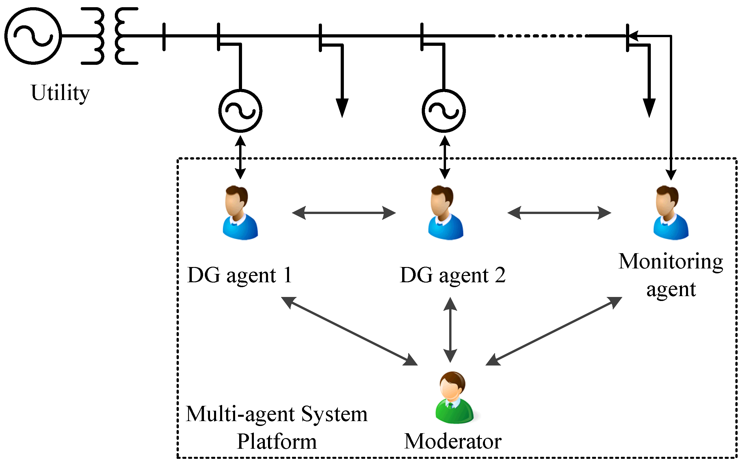
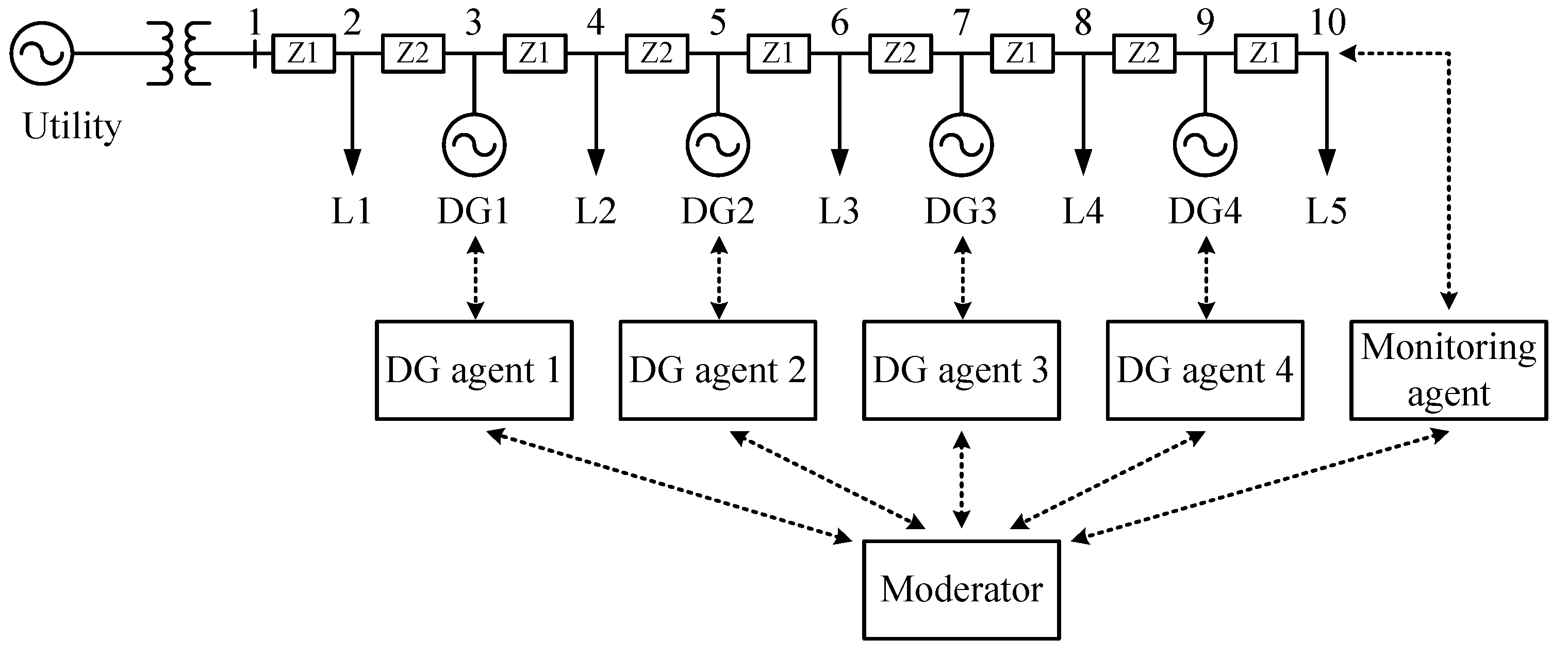
2. Voltage Regulation Using Multi-Agent System

2.1. Multi-Agent System for Voltage Regulation

We propose an MAS-based voltage regulation method that maintains voltages within a specified range in a distribution system with multiple DGs. Using the proposed method, the bus voltages in the distribution system can be controlled by coordinating the reactive power output of the DGs. Figure 1 shows the basic structure of the MAS platform. Each agent links to an electrical node of the distribution network or an output controller of a DG. There are two principle issues for the design and implementation of an MAS [21]. One is defining and classifying the role of the agent, and the other is determining how multiple agents will cooperate to achieve the global objective.
Figure 1. Schematic diagram illustrating the structure of the multi-agent system (MAS).
Energies 08 12411 g001
Three types of agent were defined: monitoring agents, DG agents and the moderator. Monitoring agents may be located at specific nodes to report on the voltage levels at strategic points in the power system. These agents monitor the local node voltage and can transmit warnings if voltage disturbances occur and request voltage compensation to restore the normal voltage levels. The nodes located farthest from the substation are strong candidates for being designated the optimal locations of the monitoring agents, because this voltage level is typically the lowest of the network. DG agents control the reactive power output of each DG to regulate the bus voltage. These DG agents must participate in the MAS-based decision-making process.
The moderator coordinates the DG agents to accomplish voltage compensation. It coordinates multiple agents to achieve a global goal, which here is voltage regulation. Contract net protocol (CNP) is widely used to coordinate multiple agents and was adopted to implement our MAS-based decision-making process. In determining the reactive power output of each DG, the moderator considers the status of the DG and the system performance. The objective of the moderator is to minimize the sum of the additional reactive power outputs by considering the reactive power margins of each DG, while maintaining the system within the operating limits. If a given DG has high reactive power output sensitivity and margin, then its participation rate in voltage regulation will be greater. The moderator is described in more detail in Section 3.

2.2. Voltage Control Process Based on Multi-Agent System

The voltage control process is conducted through CNP-based communication. CNP is a protocol that is used in MAS for sharing problem information and distributing tasks to solve the problem. To achieve this CNP-based decision-making process for the proposed voltage regulation method, the communication capability between agents should ensure that it can be done within a desired time. However, voltage regulation in a distribution system is generally a process that takes place within several seconds and minutes. Then, here, the communication time between agents would not affect its regulation result considering the baud rate for CNP. From a previous work related to this CNP-based communication, all decision-making processes could be completed within 0.5 s within a ZigBee environment for wireless personal area networking [31].
CNP is typically composed of five stages: recognition, announcement, bidding, awarding and expediting [32,33]. As a consequence, the voltage control process is implemented here in five stages, as summarized in Figure 2, and is described as follows.
Figure 2. A summary of the voltage control process.
Energies 08 12411 g002
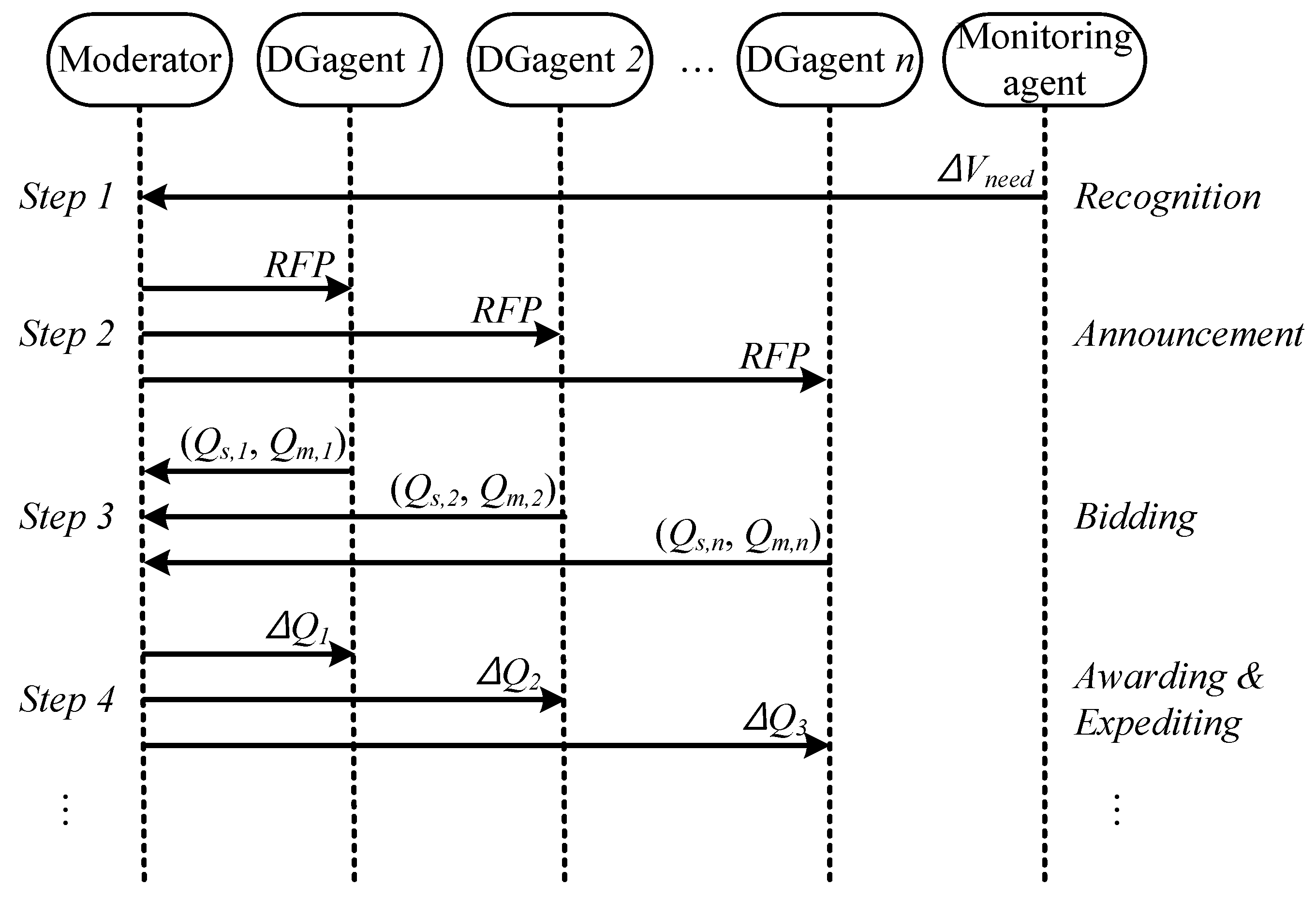
  • Recognition: In the normal state, monitoring agents measure a local node voltage. If the node voltage moves outside the predetermined range (typically ± 5 % of the rated voltage), the monitoring agent informs the moderator with a request message for voltage compensation. Therefore, the voltage deviation, Δ V d , that requires restoration to the normal state is included in this request message.
  • Announcement: Once the request message for voltage compensation has been received by the moderator, it requests voltage control proposals from all DG agents. The bidding process begins with the issuance of a request for proposal (RFP).
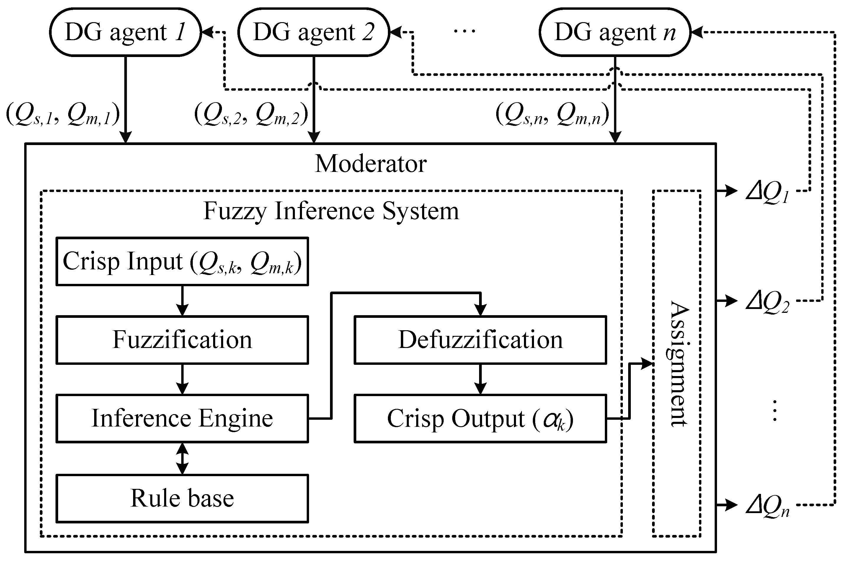
  • Bidding: DG agents respond to this RFP by sending a proposal if they are able to participate in voltage control. In this proposal, two items of power system data are included: the reactive power sensitivity, Q s , and the reactive power margin, Q m . Definitions of these quantities and the derivative methods employed to make the proposals are detailed in the following subsection.
  • Awarding: The moderator reviews the proposals and decides how much of the reactive power is to be controlled by each DG for restoring the voltage error. That is to say, the moderator assigns tasks to the DG agents. These tasks are allocated as an increase or decrease in the reactive power at one or more DGs.
  • Expediting: Finally, once the task for increasing or decreasing the reactive power of DG has been received by each DG agent, it completes the assigned task by dispatching the reactive power reference to its own DG unit.
Strictly speaking, the reactive power sensitivity is nonlinear. Since it is assumed to be linear in the proposed voltage control process, the initial voltage problem may not be mitigated completely. In this case, a new voltage control process will be initiated, with Step 1 being repeated because one or more monitoring agents detect a voltage deviation. The process is therefore repeated until Δ V d is within the predefined operating limits of the system.

2.3. Bidding

The bidding information is the reactive power sensitivity to the bus voltage, Q s , and the reactive power margin of the DG, Q m ; these criteria are used in the moderator’s decision-making model. This subsection presents the definitions of these quantities and how DG agents derive them.
The reactive power sensitivity corresponds to an incremental increase in the violated node voltage for an incremental injected reactive power. This can be determined from a simple power flow equation as follows:
Δ θ Δ V = J - 1 Δ P Δ Q
where J is the Jacobian matrix corresponding to the active and reactive powers from the bus voltage angles and magnitudes. If we assume that the injected active power does not change, we can rewrite Equation (1) as:
Δ θ Δ V = J - 1 0 Δ Q = X 11 X 12 X 21 X 22 0 Δ Q
From this expression, the relationship between the bus voltages and injected reactive power can be determined, i.e.,
Δ V = X 22 × Δ Q = Y × Δ Q
We can divide this equation into generator bus and load bus parts, as follows:
Δ V g Δ V l = Y 11 Y 12 Y 21 Y 22 Δ Q g Δ Q l
For voltage control by reactive power injection at the DGs, the change in the reactive power at the load bus can be assumed to be zero. We can then obtain a relationship between the load bus voltage and the reactive power injected by the DG bus, i.e.,
Δ V l = Y 21 × Δ Q g
and the reactive power sensitivity can be defined as:
Q s = V l Q g = Y 21
If there are p load buses and q DG buses in the distribution network, we can rewrite Equation (6) as follows:
Q s = β 11 β 12 β 1 q β 21 β 22 β 2 q β p 1 β p 2 β p q
When a voltage violation occurs at the i-th load bus, the reactive power sensitivity of each DG is given by:
Q s , 1 = β i 1 , Q s , 2 = β i 2 , , Q s , q = β i q
If each DG agent acquires Q s , as given in Equation (8), then the injected active and reactive power, as well as the network topology should be known in order to establish the power flow equation. In the proposed MAS, the injected power at the DG buses can be obtained through MAS-based communication channels among the agents. However, it is not straightforward to obtain the information describing the load buses without additional devices, such as measurement units and communication lines. In other words, to know the injected power of all buses in the distribution network, a comprehensive monitoring system is required, which may not be practical due to environmental and economic limitations. Additionally, the method described so far cannot achieve the required voltage regulation because it is essentially for distributed control.
However, reactive power sensitivity calculation in a distributed manner can be achieved by autonomous data exchange between DG agents and monitoring agents. For example, as illustrated in Figure 3, the j-th DG agent can calculate its own sensitivity factor by monitoring the voltage change, Δ V p , which is caused by increasing or decreasing the reactive power output of DG, Δ Q j [21]. Here, V p indicates the bus voltage measured at the monitoring agent node. Otherwise, the j-th DG agent may assume that the voltage change at bus p is the same as that of the local bus j in the special case of a radially-structured distribution feeder. The reactive power sensitivity corresponding to an incremental increase in the voltage-violated bus p for an incremental reactive power injection by j-th DG can be expressed as:
Figure 3. An example showing the method to calculate Q s .
Energies 08 12411 g003
Q s , j = Δ V p / Δ Q j Δ V j / Δ Q j .
The reactive power margin is also an important factor in the voltage control method, and that of the j-th DG, Q m , j , can be obtained by monitoring its reactive power output, Q o u t p u t , j , i.e.,
Q m , j = Q r a t e d , j - Q o u t p u t , j .

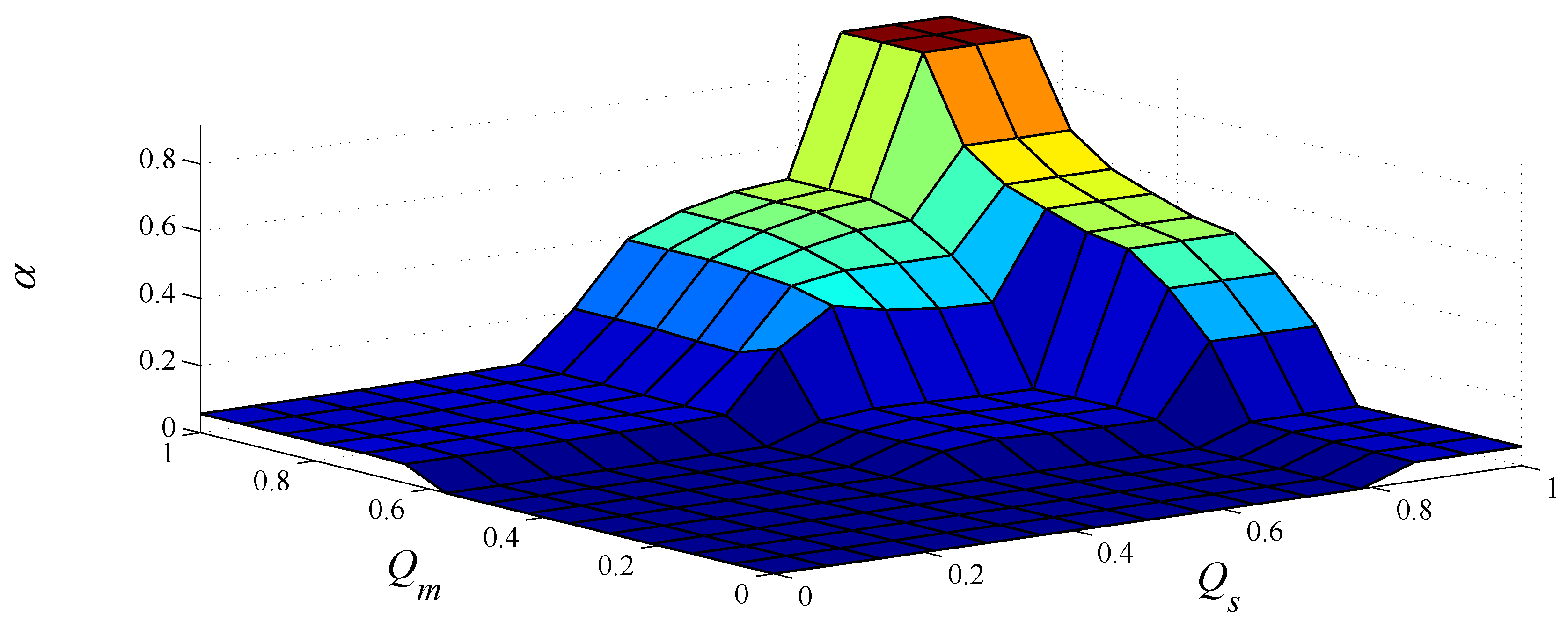
3. Moderator Design Using a Fuzzy Inference System
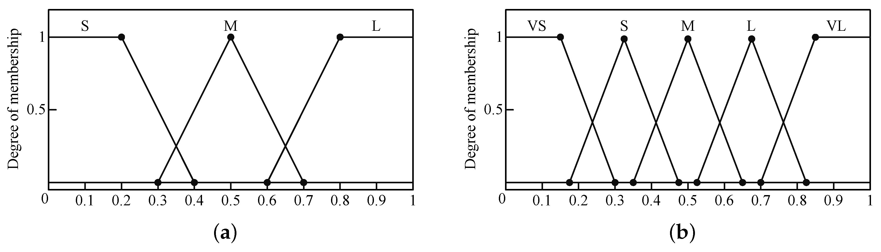
In the proposed voltage control strategy, the moderator determines the reactive power output of each DG based on the bidding information. In other words, the reactive power sensitivities and margins are the criteria for the moderator to determine the participation rate of DGs to regulate the bus voltage. The decision-making model of the moderator must reflect the main concept of the proposed voltage control strategy. Therefore, the higher the Q s and Q m of a given DG are, the more likely it is to participate in voltage regulation. However, it is nontrivial to determine the participation rate of DGs based on the two uncorrelated criteria Q s and Q m . To deal with this problem, we introduce a fuzzy logic approach. Furthermore, to make the decision-making model effective, the moderator employs the fuzzy inference system (FIS), which is an artificial intelligence technique and can reflect the views of the expert or operator [34,35]. Negnevitsky As shown in Figure 4, the FIS of the moderator determines the participation factor, α, based on the bidding information and then assigns the increase or decrease in the reactive power to the DGs. We used the Mamdani-style FIS to determine the participation factor of each DG. This method is the most commonly-used fuzzy inference technique and consists of three main stages, as shown in Figure 4: fuzzification, the rule-based inference engine and defuzzification [35].
Figure 4. Configuration of the moderator.
Energies 08 12411 g004

3.1. Fuzzification

Fuzzification is the first stage in determining the degree to which each measurement (i.e., crisp) input belongs to each of the appropriate fuzzy sets. For example, the reactive power sensitivity represents the voltage change in response to injected reactive power and is a crisp variable. However, in fuzzy set theory, we must fuzzify these numerical data against the membership degree of the appropriate linguistic fuzzy set [35].
All inputs are fuzzified using a membership function defined with three fuzzy sets, as shown in Figure 5a: S for small; M for medium; and L for large. Triangular and trapezoidal membership functions are used here, as these provide an adequate representation of the desired response of the system and significantly simplify the computational process.
Figure 5. Membership functions. (a) Two inputs and (b) An output.
Energies 08 12411 g005
The two inputs to the FIS, Q s and Q m , are delivered from the DG agents to the moderator in numerical (crisp) values. To obtain the degree of membership in fuzzification, these crisp inputs are limited to the range [0,1], and so, Q s is normalized as follows:
Q ^ s , j = Q s , j max i Q s , i
where the subscripts i and j indicate the index of the DG units. This normalization is unnecessary for the crisp values of Q m because these are represented per unit. The degree of membership of the input variables μ Q ^ s and μ Q ^ m is determined from the values corresponding to the relevant fuzzy sets.

3.2. Rule-Based Inference Engine

The fuzzy membership inputs of the inference engine are evaluated by the fuzzy rules. A typical fuzzy rule has the form “if (antecedent), then (consequent).” Here, the antecedent is a fuzzy membership input, and the consequent is the participation factor in voltage control. The membership function of the consequent is defined with five fuzzy sets, as shown in Figure 5b: VS for very small; S for small; M for medium; L for large; and VL for very large.
Table 1 shows nine fuzzy rules applied to our inference engine. For example, one of the fuzzy rules for our study is “if ( Q s is large and Q m is large), then (α is very large).” These rules are based on the voltage control strategy, which gives a DG with high reactive power sensitivity and margin a high participation factor for voltage compensation.
Table 1. Fuzzy rules for inference engine.
Q m \ Q s SML
SVSSM
MSML
LMLVL
NOTE: S=Small; M=Medium; L=Large; V=Very.

3.3. Defuzzification

Defuzzification is the final stage of the FIS and is the process for calculating crisp data from the output of the fuzzy sets determined by the inference engine. The most popular defuzzification method is the centroid technique, and it is applied to obtain participation factors of each DG. The centroid defuzzification method, which is the process for obtaining the mathematical center of gravity (COG), can be expressed as follows:
C O G = μ α ( x ) × x d x μ α ( x ) d x = α

3.4. Output of the Moderator

The moderator determines the reactive power control of each DG based on the value of α that is the output of the FIS. To assign reactive power control to the DGs, these participation factors should be normalized, i.e.,
α ^ k = α k i α i
The moderator finally assigns the tasks to the DGs to compensate for the voltage deviation so that we have:
Δ Q k = α ^ k Q s , k × Δ V d

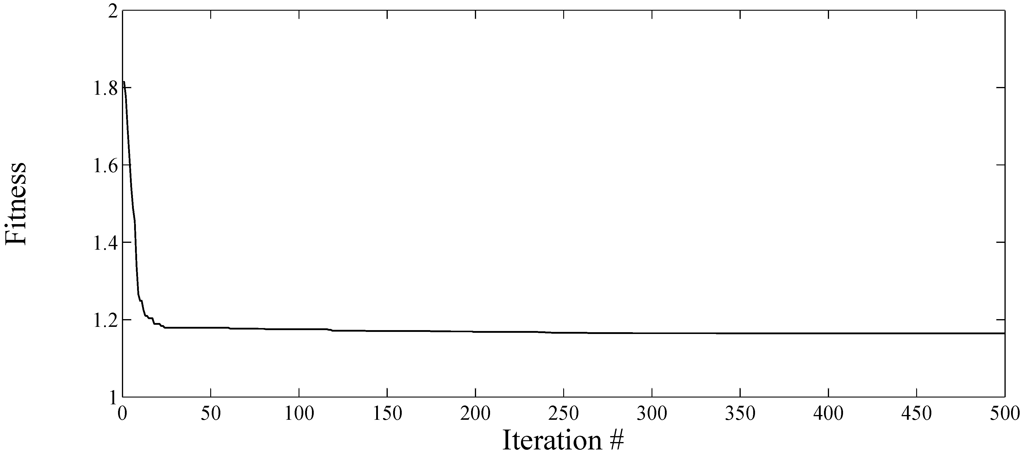
4. Optimization of the Fuzzy Inference System Using Particle Swarm Optimization

The performance of the proposed voltage control system is determined by the output of the FIS, which is strongly affected by the membership functions of the input/output fuzzy sets and the fuzzy rules of the inference engine. To enhance the decision-making performance of the system, the membership functions used in the FIS may be optimized using particle swarm optimization (PSO). In this section, the PSO algorithm is briefly introduced, and the optimization process of the FIS is described.

4.1. Particle Swarm Optimization

Particle swarm optimization is an evolutionary computation technique originally proposed by Kennedy and Eberthart in 1995, and it is widely used in optimization problems [36]. In the PSO algorithm, multiple “particles,” which represent potential solutions, are randomly moved in the search space. This iterative search process is carried out to find the optimum point corresponding to a fitness (objective) function. This optimization method exhibits a low rate of becoming trapped in local optima, as it offers a randomized and stochastic search process in an uncertain domain.
Each particle is iteratively moved in the search space to determine the optimum arrangement. During each iteration, the position information is updated, with the optimum arrangement of those trials labeled as the particle best, P b . The particles share knowledge about the best position to determine the global optimum. The next positions are dependent on the “velocity” of the particles, which is determined based on the moving inertia, its particle best, P b , and the global best, G b . The PSO algorithm can be represented as:
V i k + 1 = w × V i k + c 1 × r 1 × ( P b i k - X i k ) + c 2 × r 2 × ( G b k - X i k )
and:
X i k + 1 = X i k + V i k + 1
where i and k are the particle and iteration indices, respectively; and X and V indicate the n-dimensional position and velocity vectors, respectively. The velocity constants c 1 and c 2 are generally set to two, and the random variables r 1 and r 2 , which are in [0,1], determine stochastically the velocity of the next iteration. The inertia weight w changes from iteration to iteration as:
w = w m a x - ( w m a x - w m i n ) × k N
where N is the total number of iterations; and w m a x and w m i n are the initial and final inertia weights. Typically, these are set to w m a x = 0 . 9 and w m i n = 0 . 4 .

4.2. Optimization of the Fuzzy Inference System

The objective of the optimization of the FIS is to make the output of the FIS correspond to our voltage control strategy. The coordination strategy of the moderator assigns a high participation rate in voltage compensation to a DG that has high reactive power sensitivity and margin. In other words, the objective of voltage control is to minimize the sum of the additional reactive power injection of each DG while securing the control margin. The cost function of the i-th DG is defined as:
C i = 1 ( Q r a t e d , i - Q o u t p u t , i ) 2 × ( Δ Q i ) 2
where Q r a t e d , i is the rated reactive power; Q o u t p u t , i is the reactive output power and Δ Q i is the change in the reactive power required for voltage control.
Using this cost function, the optimal point to coordinate multiple DGs can be determined by solving the following problem:
min F = i N D G C i ( x ) , subject to 0 x 1 , for all elements V n = 0 . 95
where N D G is the total number of DGs that link to a DG agent and participate in voltage control and V n indicates the last bus voltage. The vector x is a 27-dimensional vector, the elements of which determine the membership functions of the input/output fuzzy sets, as shown with dotted points in Figure 5: each input is determined by seven points, and an output is determined by 13 points.
To establish the optimal FIS for the target distribution system, we chose c n voltage problem cases randomly and induced the FIS of the moderator via the PSO optimization, as shown in Figure 6. The particles in the swarm were defined as described above by the 27-dimensional vector, x . The basic form of the fitness function of the PSO was similar to that in Equation (19), except that it was modified to the form of the average of c n cases.
Figure 6. The PSO optimization process of the fuzzy inference system (FIS).
Energies 08 12411 g006
The optimized FIS was determined from the final output of the PSO algorithm, which was oriented only to that target distribution system. Therefore, to apply the proposed MAS-based voltage control method to a distribution system, the development of an FIS oriented to that system should be carried out.

5. Case Studies

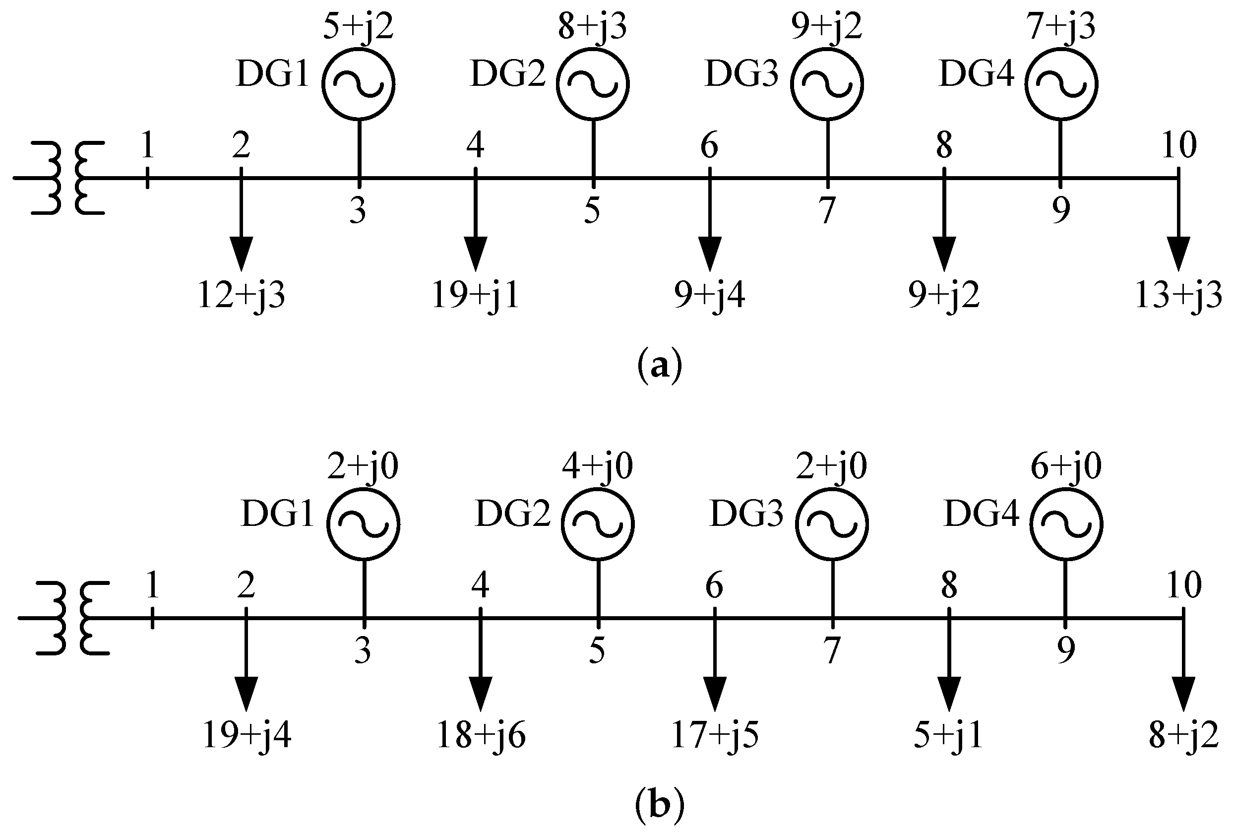
5.1. Test System and Simulation Conditions

The test system shown in Figure 7 was developed to validate the proposed MAS-based voltage control method. This test distribution system was composed of four DGs and five aggregated loads. We assume that voltage control can be accomplished by reactive power control at the DGs and that the DG agents participate in the MAS-based voltage control process. The rated active and reactive power outputs of all DGs were set to 10 kW and 4 kVar, respectively. The rated active and reactive power consumption of each of the aggregated loads was 20 kW and 10 kVar, respectively. The line impedances were 0 . 0242 + j 0 . 0194 Ω for Z 1 and 0 . 0605 + j 0 . 0486 Ω for Z 2 . For simplicity, the voltage of Bus 1 was maintained at 1 p.u. by the on-load tap changer (OLTC) of the substation. The monitoring agents can be placed at the node where the system operator wants to regulate the voltage, i.e., the node that requests voltage compensation from the moderator when a voltage problem occurs. In our case studies, the objective of voltage regulation was to keep the minimum voltage of this distribution system more than 0.95 p.u.; the monitoring agent was therefore placed at the last node.
Figure 7. The test system to simulate the voltage control method.
Energies 08 12411 g007

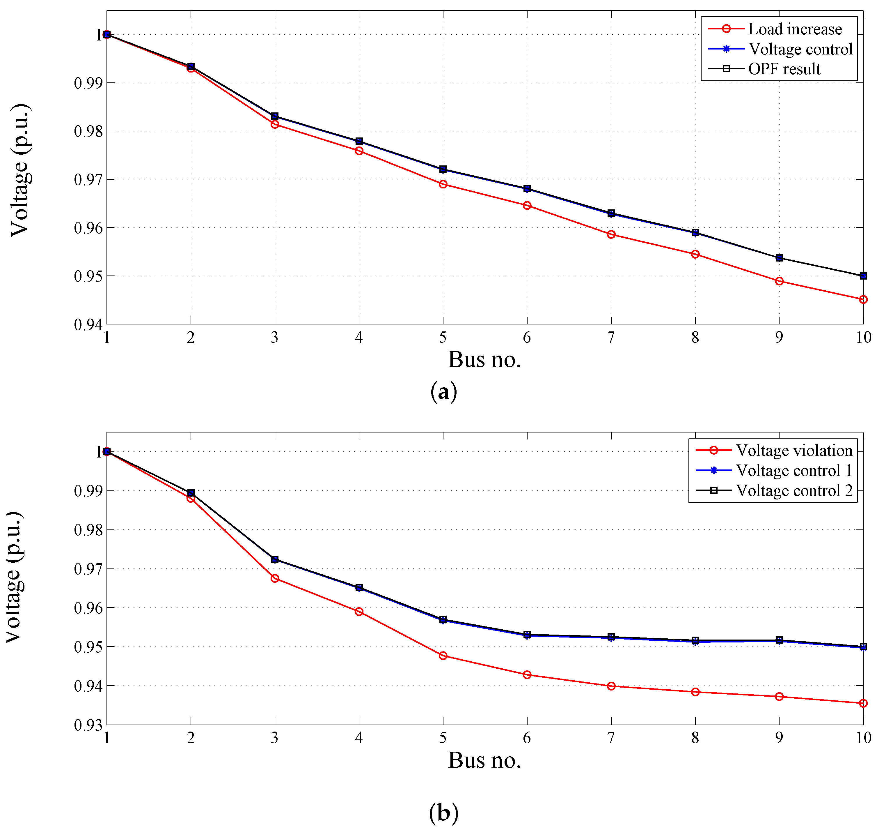
5.2. Simulation Results

First, the FIS of the moderator oriented to the target system was developed using the PSO algorithm. To establish an optimized FIS of the moderator, we randomly chose 100 power system conditions of the target test system. These conditions were limited to voltage problem cases where the voltage of the last node was less than 0.95 p.u. We then randomly generated 30 particles and determined the membership functions of the fuzzy sets after 500 iterations of the PSO algorithm. Figure 8 shows the fitness of the global best particle during the optimization. The best among the initial 30 particles had a fitness of 1.8161, whereas we finally obtained a particle with a fitness of 1.1645 at the end of the optimization. Each fuzzy set obtained following the PSO optimization is shown in Figure 9. The membership functions for VS and S in the output fuzzy set cannot be seen in the figure, as they are aligned with the x-axis. It follows that a DG that only belongs to that area does not contribute to voltage compensation. To clarify the output of the FIS rule-based evaluation, a three-dimensional plot of the fuzzy rules described in Section 3.2 is shown in Figure 10.
Figure 8. The global best particle’s fitness over the PSO iteration.
Energies 08 12411 g008
Figure 9. Optimized fuzzy sets of the moderator’s FIS. (a) Membership functions for input Q s ; (b) Membership functions for input Q m ; (c) Membership functions for output α.
Energies 08 12411 g009
Figure 10. Three-dimensional plot for rule-based evaluation.
Energies 08 12411 g010
Following the development of the decision-making model of the moderator, we studied two voltage violation cases to verify the effectiveness of the proposed voltage control method.
The first case shows the general voltage control process when the voltage problem occurs due to a load increase. Figure 11a shows the initial operating conditions for Case 1: the demand power of the loads and the output power of DGs are given in the form of P + j Q in kW and kVar. In the initial state, the voltage of the last bus was 0.9613 p.u. (normal state). The load demand of the last bus was then increased to 18 + j 4 . This increase in the load resulted in a drop in the voltage at the last bus to 0.9451 p.u. (below the limit). The monitoring agent then requested voltage compensation of Δ V d = 0 . 0049 p.u. from the moderator.
After receiving this request, the moderator issued RFPs to DG agents. The DG agents then bid for that proposal by providing the data on Q s and Q m , the values of which are listed in Table 2. The moderator determined the additional reactive power output of each DG based on these bidding data; the values of the inputs and outputs to the moderator are also listed in Table 2.
Figure 11. Initial condition of the test system. (a) Case 1; (b) Case 2.
Energies 08 12411 g011
Table 2. The simulation results for Case 1.
Unit Q s Q m Q ^ s α α ^ Δ Q (kVar)
DG agent 10.50340.750.24730.05780.05660.5454
DG agent 21.00220.500.49720.04790.04690.2247
DG agent 31.52450.750.74890.43470.42541.3547
DG agent 42.03580.5010.48160.47121.1238
Figure 12a shows the variation in the voltage profile. The abnormal state of the last bus voltage (red-circle line) was restored to the normal state (blue-star line). Additionally, the result of optimal power flow (OPF) calculation (described in the Appendix) is shown by the black square line. We find that the performance of the proposed voltage control method is similar to that of OPF. This shows that our method has good performance, even though it has little information on the power system and no power flow calculations were implemented.
The second case shows how the voltage can be recovered to within the normal range when the voltage problem cannot be resolved using a single voltage control process. In this case, the initial condition was assumed to be as shown in Figure 11b, where the last bus voltage was significantly below the normal limit, at 0.9355 p.u. This voltage problem cannot be resolved through one voltage control process, as the voltage compensation determined by Equation (14) is not sufficient. This mismatch results from the nonlinearity of the power system, and another voltage control process is required to resolve the initial voltage problem. Table 3 lists the simulation results for the first and the second iterations of the process.
In the first part of the process, all of the DGs had the same (and sufficient) reactive power margin, because they were operating in the unit power factor. Therefore, the coordination criteria to distribute the voltage compensation were mostly related to the reactive power sensitivity of the DGs. The result of bidding information and the increased reactive power output of each DG are shown in Table 3. After this first process, the last bus voltage changed to 0.9497 p.u., which was not sufficient for our operating strategy. The monitoring agent was, therefore, once again requested to compensate for a voltage deviation.
Figure 12. Voltage profiles: (a) For Case 1; and (b) For Case 2.
Energies 08 12411 g012
Table 3. The simulation results for Case 2.
Unit Q s Q m Q ^ s α α ^ Δ Q (kVar)
First process
DG agent 10.514510.24830.05910.03500.9842
DG agent 21.038310.50110.21530.12761.7777
DG agent 31.557010.75150.49670.29442.7351
DG agent 42.0718110.91620.54303.7918
Second process
DG agent 10.50060.75390.25330.05760.33270.2141
DG agent 20.99940.55560.50570.05910.34150.1101
DG agent 31.48770.31620.7527000
DG agent 41.97650.052110.05640.32580.0531
In the second part of the process, the reactive power margins were recalculated based on the new reactive power output. This took account of the reactive power sensitivity and margin of each unit. As shown in Table 3, the participation factors of DG Agents 1 and 4 were similar, even though the inputs of the FIS were significantly different. This is because the reactive power sensitivity of DG1 was smaller, but its reactive power margin was larger than that of DG4. The final reactive power outputs of DG1, DG2, DG3 and DG4 were 1.1983 kVar, 1.8878 kVar, 2.7351 kVar and 3.8449 kVar, respectively. Following this second voltage control stage, the last bus voltage was restored to within the limits. The initial voltage profile and those following voltage control process Steps 1 and 2 are shown in Figure 12b.

6. Conclusions

We have described a voltage control method using multiple DGs based on MAS to solve voltage problems in power systems in a distributed manner. Monitoring agents, DG agents and a moderator were employed to establish voltage regulation. These agents were able to cooperate to achieve voltage regulation. The local voltage was monitored at strategic locations; and alarm signals were sent to the moderator if a voltage problem was detected, and voltage compensation was requested. The DG agents then participated in a bidding process based on CNP, and the moderator coordinated the agents to achieve voltage control by dispatching the reactive power output to each DG. The moderator determined the reactive power output of each DG based on the DG status and the system performance.
The moderator used FIS to coordinate the voltage control response of multiple DGs, and the input and output fuzzy sets of the FIS were optimized to improve the decision-making process using PSO. The objective of this optimization was to minimize the sum of the additional reactive power injected by each DG by considering the reactive power margin of the DGs. We find that this voltage control process was able to regulate the voltages in the system and that the performance was similar to that obtained using OPF, even though little information on the power system was required and no power flow calculations were implemented.

Acknowledgments

This work was supported by the Korea Institute of Energy Technology Evaluation and Planning (KETEP), granted financial resource from the Ministry of Trade, Industry & Energy, Republic of Korea (No. 20151210200080) and by the National Research Foundation of Korea grant funded by the Korea government (NRF-2015R1C1A1A01054635).

Author Contributions

Hyun-Koo Kang proposed and developed the main idea of the paper and also compiled the manuscript. Il-Yop Chung advised to apply multi-agent based control algorithms to the paper. Seung-Il Moon advised to improve the simulation results of the paper.

Conflicts of Interest

The authors declare no conflict of interest.

Appendix

Optimal Power Flow Using Sequential Quadratic Programming

To validate the performance of the proposed voltage control method, the optimal power flow (OPF) problem is formulated using sequential quadratic programming (SQP). The objectives of our problem are to minimize the reactive power cost function defined as Equation (18) while maintaining the last bus voltage at the predetermined reference, which is 0.95 in this case. The optimization problem has a similar form as Equation (19), and it can be represented as:
min f = i N D G C i ( Δ Q i ) = i N D G Δ Q i Q r a t e d , i - Q ^ i 2 = i N D G 1 Q m , i × Δ Q i 2 , subject to 0 Δ Q i Q m , i , for all i V n = 0 . 95
where Δ Q i indicates the increased reactive power output of the i-th DG for restoring the last bus voltage to 0.95. Q r a t e d , i , Q m , i and Q ^ i represent the rated reactive power, the reactive power output margin and the current reactive power output of the i-th DG, respectively, and their relationship is Q m , i = Q r a t e d , i - Q ^ i .
The general matrix form of the QP is as follows.
min x 1 2 X T H X + F T X subject to A X B A eq X = B eq L B X U B
x indicates the control variable matrix that is represented as [ Δ Q 1 , Δ Q 2 , , Δ Q N D G ] T .

References

  1. Pepermans, G.; Driesen, J.; Haeseldonckx, D.; Belmans, R.; D’haeseleer, W. Distributed generation: Definition, benefits and issues. Energy Policy 2005, 33, 787–798. [Google Scholar] [CrossRef]
  2. Ackermann, T.; Andersson, G.; Söder, L. Distributed generation: A definition. Electr. Power Syst. Res. 2001, 57, 195–204. [Google Scholar]
  3. Dugan, R.C.; Mcdermott, T.E. Distributed generation. IEEE Ind. Appl. Mag. 2002, 8, 19–25. [Google Scholar]
  4. Dugan, R.C.; McDermott, T.E.; Bal, G.J. Planning for distributed generation. IEEE Ind. Appl. Mag. 2001, 7, 80–88. [Google Scholar] [CrossRef]
  5. Mao, Y.; Miu, K. Switch placement to improve system reliability for radial distribution systems with distributed generation. IEEE Trans. Power Syst. 2003, 18, 1346–1352. [Google Scholar]
  6. Delfino, B. Modeling of the integration of distributed generation into the electrical system. In Proceedings of the Power Engineering Society Summer Meeting, Chicago, IL, USA, 25–25 July 2002; Volume 1, pp. 170–175.
  7. Ochoa, L.F.; Padilha-Feltrin, A.; Harrison, G.P. Evaluating distributed generation impacts with a multiobjective index. IEEE Trans. Power Deliv. 2006, 21, 1452–1458. [Google Scholar] [CrossRef]
  8. Walling, R.; Saint, R.; Dugan, R.C.; Burke, J.; Kojovic, L.A. Summary of distributed resources impact on power delivery systems. IEEE Trans. Power Deliv. 2008, 23, 1636–1644. [Google Scholar] [CrossRef]
  9. Barker, P.P.; De Mello, R.W. Determining the impact of distributed generation on power systems. I. Radial distribution systems. In Proceedings of the Power Engineering Society Summer Meeting, Seattle, WA, USA, 16–20 July 2000; Volume 3, pp. 1645–1656.
  10. Std, ANSI C84. 1-2011. American National Standard For Electric Power Systems and Equipment-Voltage Ratings (60 Hertz). 2011. Avaliable online: https://www.nema.org/Standards/ComplimentaryDocuments/Contents-and-Scope-ANSI-C84-1-2011.pdf (accessed on 20 September 2015 ).
  11. Kersting, W.H. Distribution System Modeling and Analysis; Chemical Rubber Company (CRC) Press: Boca Raton, FL, USA, 2012. [Google Scholar]
  12. Dai, C.; Baghzouz, Y. On the voltage profile of distribution feeders with distributed generation. In Proceedings of the Power Engineering Society General Meeting, Toronto, ON, Canada, 13–17 July 2003; Volume 2.
  13. Masters, C. Voltage rise: The big issue when connecting embedded generation to long 11 kV overhead lines. Power Eng. J. 2002, 16, 5–12. [Google Scholar] [CrossRef]
  14. Carvalho, P.; Correia, P.F.; Ferreira, L.A. Distributed reactive power generation control for voltage rise mitigation in distribution networks. IEEE Trans. Power Syst. 2008, 23, 766–772. [Google Scholar] [CrossRef]
  15. Hashim, T.T.; Mohamed, A.; Shareef, H. A Review on Voltage Control Methods for Active Distribution Networks; Przeglad Elektrotechniczny (Electrical Review): Warszawa, Poland, 2012; pp. 304–312. Available online: http://www.red.pe.org.pl/articles/2012/6/71.pdf (accessed on 20 September 2015).
  16. Tonkoski, R.; Lopes, L.A.; El-Fouly, T.H. Coordinated active power curtailment of grid connected PV inverters for overvoltage prevention. IEEE Trans. Sustain. Energy 2011, 2, 139–147. [Google Scholar] [CrossRef]
  17. Viawan, F.; Karlsson, D. Combined local and remote voltage and reactive power control in the presence of induction machine distributed generation. IEEE Trans. Power Syst. 2007, 22, 2003–2012. [Google Scholar] [CrossRef]
  18. McArthur, S.D.; Davidson, E.M.; Catterson, V.M.; Dimeas, A.L.; Hatziargyriou, N.D.; Ponci, F.; Funabashi, T. Multi-agent systems for power engineering applications—Part I: Concepts, approaches, and technical challenges. IEEE Trans. Power Syst. 2007, 22, 1743–1752. [Google Scholar] [CrossRef] [Green Version]
  19. Rehtanz, C. Autonomous Systems and Intelligent Agents in Power System Control and Operation; Springer-Verlag: Berlin/Heidelberg, Germany, 2003. [Google Scholar]
  20. Wooldridge, M. An Introduction to Multiagent Systems; John Wiley & Sons: Chichester, West Sussex, UK, 2009. [Google Scholar]
  21. Baran, M.E.; El-Markabi, I.M. A multiagent-based dispatching scheme for distributed generators for voltage support on distribution feeders. IEEE Trans. Power Syst. 2007, 22, 52–59. [Google Scholar] [CrossRef]
  22. Elkhatib, M.E.; El-Shatshat, R.; Salama, M. Novel coordinated voltage control for smart distribution networks with DG. IEEE Trans. Smart Grid 2011, 2, 598–605. [Google Scholar] [CrossRef]
  23. Farag, H.E.; El-Saadany, E.F. A novel cooperative protocol for distributed voltage control in active distribution systems. IEEE Trans. Power Syst. 2013, 28, 1645–1656. [Google Scholar] [CrossRef]
  24. Spatti, D.H.; Da Silva, I.N.; Usida, W.F.; Flauzino, R.A. Real-time voltage regulation in power distribution system using fuzzy control. IEEE Trans. Power Deliv. 2010, 25, 1112–1123. [Google Scholar] [CrossRef]
  25. Liang, R.H.; Wang, Y.S. Fuzzy-based reactive power and voltage control in a distribution system. IEEE Trans. Power Deliv. 2003, 18, 610–618. [Google Scholar] [CrossRef]
  26. Miranda, V.; Moreira, A.; Pereira, J. An improved fuzzy inference system for voltage/VAR control. IEEE Trans. Power Syst. 2007, 22, 2013–2020. [Google Scholar] [CrossRef]
  27. Rigatos, G.; Siano, P.; Yousef, H. Adaptive fuzzy control based on output feedback for synchronization of distributed power generators. In Proceedings of the 3rd International Symposium on Energy Chanllenfes and Mechanics (ECM 2015), Aberdeen, UK, 7–9 July 2015.
  28. Tomescu, M.L.; Preitl, S.; Precup, R.E.; Tar, J.K. Stability analysis method for fuzzy control systems dedicated controlling nonlinear processes. Acta Polytech. Hung. 2007, 4, 127–141. [Google Scholar]
  29. Liu, J.; Liu, H.; Shen, W. Stability analysis of particle swarm optimization. In Advanced Intelligent Computing Theories and Applications. With Aspects of Artificial Intelligence; Springer-Verlag: Berlin/Heidelberg, Germany, 2007; pp. 781–790. [Google Scholar]
  30. Moreau, L. Stability of multiagent systems with time-dependent communication links. IEEE Trans. Autom. Control 2005, 50, 169–182. [Google Scholar] [CrossRef]
  31. Oh, S.; Yoo, C.; Chung, I.; Won, D. Hardware-in-the-loop simulation of distributed intelligent energy management system for microgrids. Energies 2013, 6, 3263–3283. [Google Scholar] [CrossRef]
  32. Smith, R.G. The contract net protocol: High-level communication and control in a distributed problem solver. IEEE Trans. Comput. 1980, 29, 1104–1113. [Google Scholar] [CrossRef]
  33. Alibhai, Z. What is Contract Net Interaction Protocol? Intelligent Robotics and Manufacturing Systems (IRMS) Laboratory, Simon Fraser University: Vancouver, BC, Canada, 2003. [Google Scholar]
  34. Ross, T.J. Fuzzy Logic with Engineering Applications, 3rd ed.; John Wiley & Sons: Chichester, West Sussex, UK, 2009. [Google Scholar]
  35. Negnevitsky, M. Artificial Intelligence: A Guide to Intelligent Systems; Pearson Education: Harlow, Essex, UK, 2005. [Google Scholar]
  36. Kennedy, J.; Eberhart, R. Particle swarm optimization. In Proceedings of the IEEE International Conference on Neural Network, Piscataway, NJ, USA, 1995; pp. 1942–1948.

