Technical Note

A Simple Expression for the Tortuosity of Gas Transport Paths in Solid Oxide Fuel Cells’ Porous Electrodes

School of Energy and Power Engineering, Jiangsu University of Science and Technology, Zhenjiang 212003, China
*
Author to whom correspondence should be addressed.
These authors contributed equally to this work.
Energies 2015, 8(12), 13953-13959; https://doi.org/10.3390/en81212406
Submission received: 28 October 2015 / Revised: 23 November 2015 / Accepted: 1 December 2015 / Published: 9 December 2015
(This article belongs to the Special Issue Solid Oxide Fuel Cells)

Abstract

:
Based on the three-dimensional (3D) cube packing model, a simple expression for the tortuosity of gas transport paths in solid oxide fuel cells’ (SOFC) porous electrodes is developed. The proposed tortuosity expression reveals the dependence of the tortuosity on porosity, which is capable of providing results that are very consistent with the experimental data in the practical porosity range of SOFC. Furthermore, for the high porosity (>0.6), the proposed tortuosity expression is also accurate. This might be helpful for understanding the physical mechanism for the tortuosity of gas transport paths in electrodes and the optimization electrode microstructure for reducing the concentration polarization.

Graphical Abstract

1. Introduction

Emerging as an attractive device for future power plants, solid oxide fuel cells (SOFC) enjoy some advantages, such as higher energy conversion efficiency, quiet operation, fuel flexibility, and low environmental hazards. In recent years, significant strides have been made in improving SOFC performance [1,2,3]. In other words, for a given operating voltage, the output current density has been increased drastically. For example, the output current density of a single SOFC can reach 3.5 A·cm−2 at 0.7 V [4]. However, the higher the output current density is, the more serious the concentration polarization is. Thus, the accurate modeling of gas transport in electrodes is essential for the understanding and prediction of the concentration polarization and fuel cell performance. However, it is a challenging task to simulate the gas transport in electrodes accurately because the presence of the solid phase causes the transport paths of gas to deviate from straight lines. In order to take the effect of tortuous gas transport paths into account, the effective gas diffusion coefficient D eff is usually corrected by introducing the tortuosity, which is commonly expressed as [5,6,7,8,9]:
D eff = ε τ 2 D 0
where D 0 is the bulk gas diffusion coefficient, ε is the porosity of the electrode, and τ (τ = Leff/L0) is the tortuosity of the gas transport paths, which is the ratio of the average actual path length ( L eff ) to the straight distance ( L 0 ). It should be noted that the square of tortuosity is equal to the tortuosity factor.
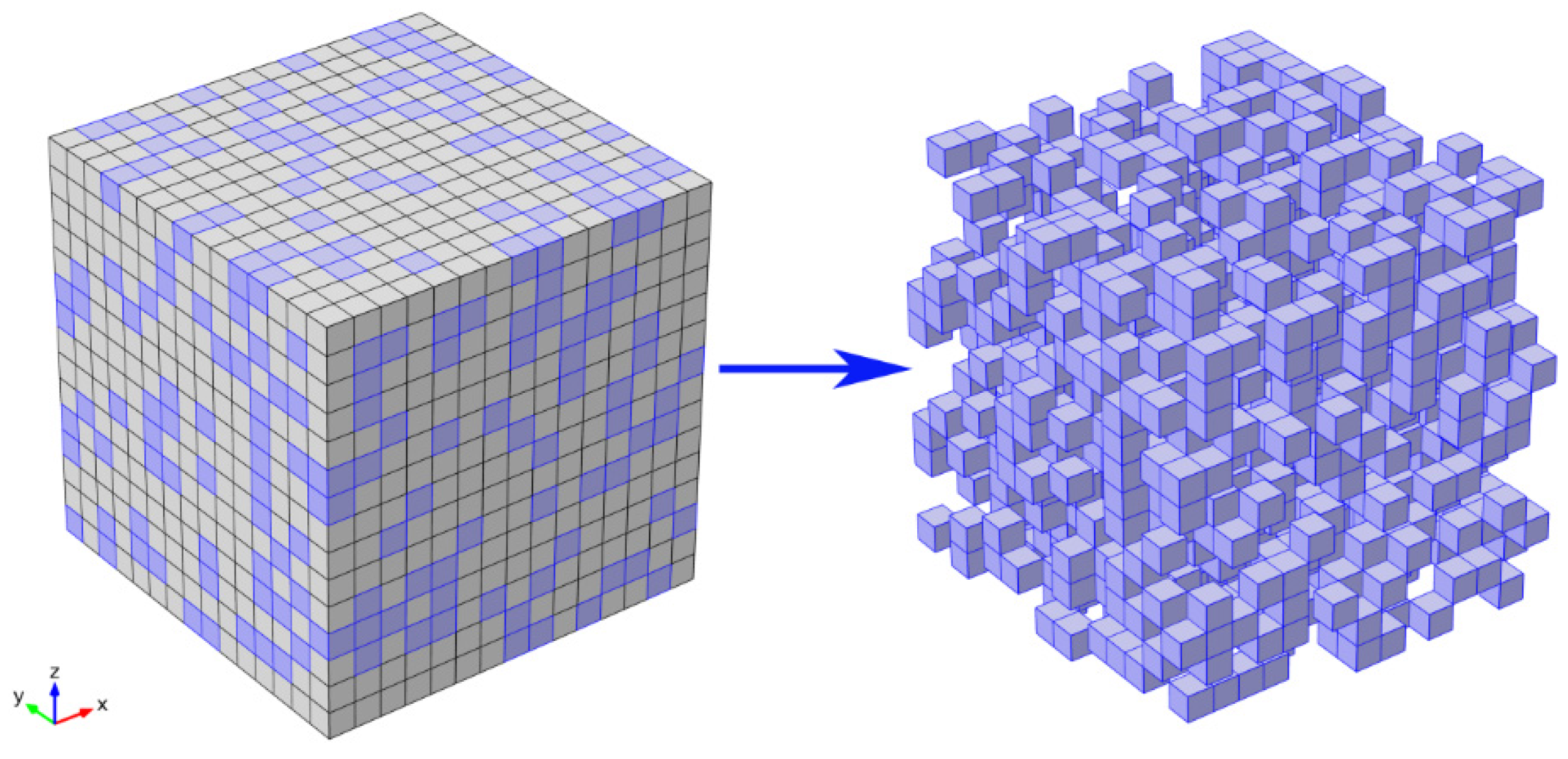
Although Equation (1) is widely adopted in SOFC literature, the studies on tortuosity are limited, which includes experimental and numerical approaches [10,11,12,13]. Wilson et al. [14] reconstructed the three-dimensional (3D) microstructure of an electrode employing the focused ion beam-scanning electron microscope (FIB–SEM) technique, and then the tortuosity is estimated by solving the diffusion equation in the pore phase. Based on the microstructure of the electrode obtained by FIB–SEM, Iwai et al. [15] adopted the random walk calculation and the lattice Boltzmann method (LBM), which are two different methods to calculate tortuosity factor. Although the FIB–SEM experimental method provides valuable information about tortuosity, it is not predictive and relies on specific sophisticated equipment. For the numerical approach, the 3D sphere packing model is widely adopted. The electrode microstructure is modeled by a set of the random packing spheres, and is used as the geometry structure for the transport model. The tortuosity can be quantitatively evaluated by solving the transport equation [16,17]. However, the tortuosity value predicted by the 3D sphere packing model is smaller than the experimental data. In order to address this issue, the 3D cube packing model was proposed by the author [11]. In this approach, the electrode representative volume element (RVE) consists of a cubic lattice ( N x × N y × N z where lattice units, N x , N y and N z are respectively the number of lattice units in x, y and z directions) in which ε × N x × N y × N z lattice units are randomly selected as the pore-forming pore phase in the electrode, as depicted in Figure 1. Baseed on this new electrode microstructure, the tortuosity can be obtained by solving the diffusion equation. The good agreement with experimental data verifies the accuracy of this method.
Figure 1. Schematic of solid oxide fuel cells (SOFC) electrode microstructure; blue is pore phase, gray denotes solid phase.
Energies 08 12406 g001
As a key factor for D eff determination, tortuosity is a critical input parameter in SOFC multiphysics models of the cell level. However, there is still a lack of an effective method to determine the tortuosity in the entire porosity scope of SOFC electrodes, which leads to a big disagreement about tortuosity. As a result, the tortuosity is usually set as an empirical value randomly or used as an adjustable parameter to fit experimental data in modeling studies [17,18], which may nullify the subsequent modeling result.
Based on the 3D cube packing model, the objective of this paper is to derive a simple and effective expression for tortuosity calculation and eliminate the uncertainty of tortuosity. The derived expression not only reveals the gas diffusion mechanism in porous electrodes, but also provides a trustworthy tortuosity evaluation criterion for SOFC modeling, which will be helpful to optimize the electrode microstructure and improve SOFC performance.

2. Theory

For the 3D cube packing model, in the arbitrary layer (perpendicular to z direction), there is the ε × N x × N y lattice unit for the pores due to the random pore distribution in electrodes [11]. Likewise, the location relationship among pores in the two arbitrary adjacent layers is also similar. Consequently, the two arbitrary adjacent layers are selected as the objects, as shown in Figure 2a, which are named the n layer and the n + 1 layer, respectively, for the above layer and the below layer. Gas transporting from the n layer to the n + 1 layer mainly follows two typical paths. Figure 2b displays the first typical path, which is the simplest situation. The lattice unit in the n layer is porous, under which the lattice unit in the n + 1 layer is also porous. The cross-section of the first typical path can be determined from the following equation:
S 1 = ε 2 S 0
where S 1 is the cross-section of the first path, and S 0 is the cross-section of RVE. This is because the probability of a lattice unit as a pore is porosity ε . The second typical path is displayed in Figure 2c. Here there is a pore lattice unit connecting to the first typical path in the n layer, under which the lattice unit is solid. The cross-section of the second typical path S 2 can be written as:
S 2 = S 0 ε 2 ( 1 1 + ε ) ( ε 1 + ε ) ( 4 4 ε )
Equation (3) is complex, and it is derived by following steps. For the second typical path, it has to satisfy the following conditions:
(1) There is a first typical path, the probability of which is ε2.
(2) In the second typical path a pore lattice unit connects to the first typical path in the n layer, under which the lattice unit is solid in the n + 1 layer.
Figure 2. Sketch map for the derivation of the S 1 and S 2 : (a) schematic of the location relationship among pores in the two arbitrary adjacent layers; (b) schematic of the first typical path; (c) schematic of the second typical path; (d) schematic of the lattice units connecting to the first typical path.
Energies 08 12406 g002
A pore lattice unit in the first typical path contacts with four lattice units in the n or n + 1 layer, which are labeled as A1, A2, A3 and A4 (B1, B2, B3 and B4) in the n (n + 1) layer respectively, as displayed in Figure 2d. The probability for one of these four lattice units to be a pore and the lattice unit under this lattice unit to be a solid is [ ( ε - ε 2 ) / ( 1 - ε 2 ) ] [ ( 1 - ε ) / ( 1 - ε 2 ) ] = ε / ( 1 + ε ) 2 .
In the n + 1 layer, a pore lattice unit contacts with 4ε pore lattice units on average, according to the coordination number theory. In order to avoid the appearance of the first typical path, there are only 4 − 4ε lattice units left to possibly form the second typical path, because the probability of the first typical path has been included in ε2. For example, the B1 lattice unit is a pore for ε = 0.25. As shown in Figure 2d, if the A1 lattice unit is also a pore, the first typical path will be formed, which is not allowed. Therefore, A2, A3 and A4 lattice units are possible pores, except for the A1 lattice unit.
Gas transported from the top layer to the bottom layer follows many tortuous paths, each of which consists of many of the first and second typical paths. As a consequence, the average length of these tortuous paths (Leff) is determined by:
L eff = τ L 0
where L 0 is the length of RVE along the transport direction.
On average, the total cross-section area of these tortuous paths (St) may be evaluated by the following equation:
S t = S 1 + S 2 = S 0 ε 2 + S 0 ε 2 ( 1 1 + ε ) ( ε 1 + ε ) ( 4 4 ε )
The molar flux of gas may be written as:
N = S t D c up c bot L eff
where N is the molar flux, D is the diffusion coefficient of gas, cup (cbot) is the molar concentration of gas at the top (bottom) surface of RVE.
Based on the effective media theory, the molar flux of gas can be rewritten as:
N = S 0 D eff c up c bot L 0
Comparing Equations (6) and (7) gives:
D eff D = ε τ [ ε + 4 ε 2 ( 1 ε ) ( 1 + ε ) 2 ]
The formula of tortuosity is obtained by comparing Equations (1) and (8), which is estimated as:
τ = ( 1 + ε ) 2 ε ( 1 + ε ) 2 + 4 ε 2 ( 1 ε )

3. Results and Discussion

Figure 3 shows the tortuosity for different porosities established by different approaches. Clearly, the Equation (9) results agree very well with the experiment results, indicating that Equation (9) is capable of reliably predicting the tortuosity of gas transport paths in SOFC porous electrodes. However, the tortuosity predicted by the 3D sphere packing model is much smaller than the experiment results. The reasons can be found in our previous study [11].
Figure 3. The tortuosity for different porosities. The open circle symbols denote experiment results [15,19,20,21,22,23,24,25,26,27], line + solid triangle symbols denote the results calculated by Equation (9), solid square symbols denote the results calculated by the 3D sphere packing model [17].
Energies 08 12406 g003
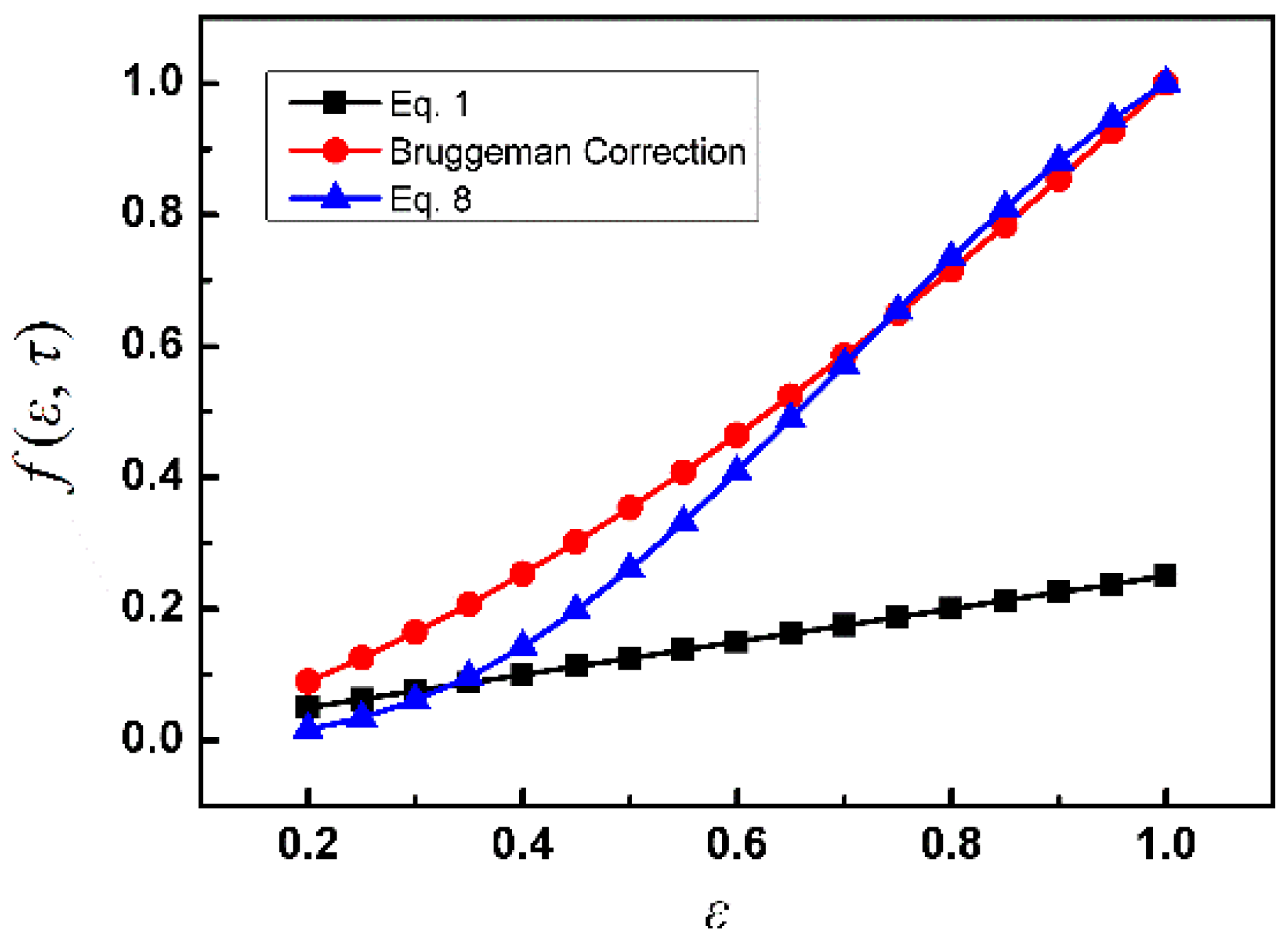
Figure 4 shows the dependence of f ( ε , τ ) ( = D eff / D 0 ) on porosity. Equation (1) ( = D eff / D 0 = ε / τ 2 ) and the Bruggeman correction ( = D eff / D 0 = ε 1.5 ) are widely used in SOFC models. Berson et al. [16] reported that Bruggeman correction, which was only valid for ε > 0.6 , introduced big errors in low porosity. For ε > 0.6 , the Equation (9) results approximately equate to the Bruggeman correction results, which demonstrates that Equation (9) is also suitable for high porosity.
Figure 4. The impacts of porosity on f ( ε , τ ) ( = D eff / D 0 ) .
Energies 08 12406 g004
However, the relationship between porosity and tortuosity is not given in Equation (1) (the parallel-capillary model). The tortuosity is often used as an adjustable parameter to fit experimental data. In Figure 4, the tortuosity factor is four for the parallel-capillary model, which is independent of porosity. As a result, f ( ε , τ ) is linear to the porosity. For ε = 1 , the value of f ( ε , τ ) is only 0.25 according to the parallel-capillary model. This contradicts with the fact that f ( ε , τ ) equates to 1 for ε = 1 .

4. Summary

In the present study, a simple expression for the tortuosity of gas transport paths in SOFC porous electrodes is derived, which shows the dependence of the tortuosity on porosity. The proposed tortuosity expression is suitable for not only the practical porosity range of SOFC, but also high porosity (ε > 0.6). Consequently, the proposed tortuosity expression might be helpful for the optimization electrode microstructure to reduce the concentration polarization and further improve SOFC performance.

Acknowledgments

This work was supported by the financial support of the National Science Foundation of China (21406095), the Jiangsu Province Colleges and Universities Natural Science Projects (13KJB480003), Colleges and universities in Jiangsu high-tech ship collaborative innovation center/Jiangsu University of Science and Technology institute of Marine equipment (HZ2015003) and the Natural Science Foundation of Jiangsu Province General Program (BK20151325).

Author Contributions

Wei Kong derived the expression and wrote the paper; Qiang Zhang analyzed the data; Xiuwen Xu and Daifen Chen prepared the figures and revised the paper.

Conflicts of Interest

The authors declare no conflict of interest.

Nomenclature

D 0
Bulk gas diffusion coefficient
D eff
Effective gas diffusion coefficient
ε
Porosity of electrode
τ
Tortuosity of gas transport paths
L 0
Straight distance
L eff
Average actual path length
N x , N y , N z
Number of lattice unit in x, y and z direction
S 0
Cross-section of representative volume element
S 1
Cross-section of the first typical path
S 2
Cross-section of the second typical path
S t
Total cross section area of the tortuous paths
N
Molar flux
c up ( c bot )
Molar concentration of gas at the top (bottom) surface of representative volume element

References

  1. Mukhopadhyay, M.; Mukhopadhyay, J.; Das Sharma, A.; Basu, R.N. Effect of anode configuration on electrical properties and cell polarization in planar anode supported SOFC. Solid State Ion. 2013, 233, 20–31. [Google Scholar] [CrossRef]
  2. Yan, M.; Fu, P.; Chen, Q.Y.; Wang, Q.W.; Zeng, M.; Pandit, J. Electrical performance and carbon deposition differences between the bi-layer interconnector and conventional straight interconnector solid oxide fuel cell. Energies 2014, 7, 4601–4613. [Google Scholar] [CrossRef]
  3. Zhang, Z.; Chen, J.; Yue, D.; Yang, G.; Ye, S.; He, C.; Wang, W.; Yuan, J.; Huang, N. Three-dimensional CFD modeling of transport phenomena in a cross-flow anode-supported planar SOFC. Energies 2013, 7, 80–98. [Google Scholar] [CrossRef]
  4. Mukhopadhyay, M.; Mukhopadhyay, J.; Das Sharma, A.; Basu, R.N. Engineered anode structure for enhanced electrochemical performance of anode-supported planar solid oxide fuel cell. Int. J. Hydrog. Energy 2012, 37, 2524–2534. [Google Scholar] [CrossRef]
  5. Zheng, K.; Li, L.; Ni, M. Investigation of the electrochemical active thickness of solid oxide fuel cell anode. Int. J. Hydrog. Energy 2014, 39, 12904–12912. [Google Scholar] [CrossRef]
  6. Cui, D.; Yang, C.; Huang, K.; Chen, F. Effects of testing configurations and cell geometries on the performance of a SOFC: A modeling approach. Int. J. Hydrog. Energy 2010, 35, 10495–10504. [Google Scholar] [CrossRef]
  7. Kong, W.; Gao, X.; Liu, S.; Su, S.; Chen, D. Optimization of the interconnect ribs for a cathode-supported solid oxide fuel cell. Energies 2014, 7, 295–313. [Google Scholar] [CrossRef]
  8. Chen, D.; Wang, H.; Zhang, S.; Tade, M.O.; Chen, H.; Shao, Z. Multi-scale model for solid oxide fuel cell with electrode containing mixed conducting material. AIChE J. 2015, 61, 3786–3803. [Google Scholar] [CrossRef]
  9. Kong, W.; Li, J.; Liu, S.; Lin, Z. The influence of interconnect ribs on the performance of planar solid oxide fuel cell and formulae for optimal rib sizes. J. Power Sources 2012, 204, 106–115. [Google Scholar] [CrossRef]
  10. Lichtner, A.Z.; Jauffrès, D.; Roussel, D.; Charlot, F.; Martin, C.L.; Bordia, R.K. Dispersion, connectivity and tortuosity of hierarchical porosity composite SOFC cathodes prepared by freeze-casting. J. Eur. Ceram. Soc. 2015, 35, 585–595. [Google Scholar] [CrossRef]
  11. Kong, W.; Zhang, Q.; Gao, X.; Zhang, J.; Chen, D.; Su, S. A method for predicting the tortuosity of pore phase in solid oxide fuel cells electrode. Int. J. Electrochem. Sci. 2015, 10, 5800–5811. [Google Scholar]
  12. Espinoza, M.; Sundén, B.; Andersson, M.; Yuan, J. Analysis of porosity and tortuosity in a 2d selected region of solid oxide fuel cell cathode using the lattice boltzmann method. ECS Trans. 2015, 65, 59–73. [Google Scholar] [CrossRef]
  13. Zheng, K.; Zhang, Y.; Li, L.; Ni, M. On the tortuosity factor of solid phase in solid oxide fuel cell electrodes. Int. J. Hydrog. Energy 2015, 40, 665–669. [Google Scholar] [CrossRef]
  14. Wilson, J.R.; Cronin, J.S.; Duong, A.T.; Rukes, S.; Chen, H.-Y.; Thornton, K.; Mumm, D.R.; Barnett, S. Effect of composition of (La0.8Sr0.2MnO3–Y2O3-stabilized ZrO2) cathodes: Correlating three-dimensional microstructure and polarization resistance. J. Power Sources 2010, 195, 1829–1840. [Google Scholar] [CrossRef]
  15. Iwai, H.; Shikazono, N.; Matsui, T.; Teshima, H.; Kishimoto, M.; Kishida, R.; Hayashi, D.; Matsuzaki, K.; Kanno, D.; Saito, M.; et al. Quantification of SOFC anode microstructure based on dual beam FIB-SEM technique. J. Power Sources 2010, 195, 955–961. [Google Scholar] [CrossRef]
  16. Berson, A.; Choi, H.W.; Pharoah, J.G. Determination of the effective gas diffusivity of a porous composite medium from the three-dimensional reconstruction of its microstructure. Phys. Rev. E 2011, 83. [Google Scholar] [CrossRef] [PubMed]
  17. Bertei, A.; Nucci, B.; Nicolella, C. Microstructural modeling for prediction of transport properties and electrochemical performance in SOFC composite electrodes. Chem. Eng. Sci. 2013, 101, 175–190. [Google Scholar] [CrossRef]
  18. Andersson, M.; Yuan, J.; Sundén, B. Review on modeling development for multiscale chemical reactions coupled transport phenomena in solid oxide fuel cells. Appl. Energy 2010, 87, 1461–1476. [Google Scholar] [CrossRef]
  19. Cooper, S.J.; Kishimoto, M.; Tariq, F.; Bradley, R.S.; Marquis, A.J.; Brandon, N.P.; Kilner, J.A.; Shearing, P.R. Microstructural analysis of an LSCF cathode using in situ tomography and simulation. ECS Trans. 2013, 57, 2671–2678. [Google Scholar] [CrossRef]
  20. Gostovic, D.; Smith, J.; Kundinger, D.; Jones, K.; Wachsman, E. Three-dimensional reconstruction of porous LSCF cathodes. Electrochem. Solid-State Lett. 2007, 10, B214–B217. [Google Scholar] [CrossRef]
  21. Joos, J.; Ender, M.; Carraro, T.; Weber, A.; Ivers-Tiffée, E. Representative volume element size for accurate solid oxide fuel cell cathode reconstructions from focused ion beam tomography data. Electrochim. Acta 2012, 82, 268–276. [Google Scholar] [CrossRef]
  22. Kishimoto, M.; Miyawaki, K.; Iwai, H.; Saito, M.; Yoshida, H. Effect of composition ratio of Ni-YSZ anode on distribution of effective three-phase boundary and power generation performance. Fuel Cells 2013, 13, 476–486. [Google Scholar] [CrossRef]
  23. Gunda, N.S.K.; Choi, H.-W.; Berson, A.; Kenney, B.; Karan, K.; Pharoah, J.G.; Mitra, S.K. Focused ion beam-scanning electron microscopy on solid-oxide fuel-cell electrode: Image analysis and computing effective transport properties. J. Power Sources 2011, 196, 3592–3603. [Google Scholar] [CrossRef]
  24. Kishimoto, M.; Iwai, H.; Saito, M.; Yoshida, H. Quantitative evaluation of solid oxide fuel cell porous anode microstructure based on focused ion beam and scanning electron microscope technique and prediction of anode overpotentials. J. Power Sources 2011, 196, 4555–4563. [Google Scholar] [CrossRef]
  25. Usseglio-Viretta, F.; Laurencin, J.; Delette, G.; Villanova, J.; Cloetens, P.; Leguillon, D. Quantitative microstructure characterization of a Ni–YSZ bi-layer coupled with simulated electrode polarisation. J. Power Sources 2014, 256, 394–403. [Google Scholar] [CrossRef]
  26. Wargo, E.A.; Kotaka, T.; Tabuchi, Y.; Kumbur, E.C. Comparison of focused ion beam versus nano-scale X-ray computed tomography for resolving 3-D microstructures of porous fuel cell materials. J. Power Sources 2013, 241, 608–618. [Google Scholar] [CrossRef]
  27. Brus, G.; Miyawaki, K.; Iwai, H.; Saito, M.; Yoshida, H. Tortuosity of an SOFC anode estimated from saturation currents and a mass transport model in comparison with a real micro-structure. Solid State Ion. 2014, 265, 13–21. [Google Scholar] [CrossRef]