
Asymptotic Solutions of Serial Radial Fuel Shuffling

Institute for Nuclear and Energy Technologies (IKET), Karlsruhe Institute of Technology (KIT), Hermann-von-Helmholtz-Platz 1, Eggenstein-Leopoldshafen D-76344, Germany
*
Author to whom correspondence should be addressed.
Energies 2015, 8(12), 13829-13845; https://doi.org/10.3390/en81212398
Submission received: 16 October 2015
/
Revised: 20 November 2015
/
Accepted: 24 November 2015
/
Published: 4 December 2015
(This article belongs to the Special Issue Sustainable Future of Nuclear Power)
Abstract
:In this paper, the mechanism of traveling wave reactors (TWRs) is investigated from the mathematical physics point of view, in which a stationary fission wave is formed by radial fuel drifting. A two dimensional cylindrically symmetric core is considered and the fuel is assumed to drift radially according to a continuous fuel shuffling scheme. A one-group diffusion equation with burn-up dependent macroscopic coefficients is set up. The burn-up dependent macroscopic coefficients were assumed to be known as functions of neutron fluence. By introducing the effective multiplication factor keff, a nonlinear eigenvalue problem is formulated. The 1-D stationary cylindrical coordinate problem can be solved successively by analytical and numerical integrations for associated eigenvalues keff. Two representative 1-D examples are shown for inward and outward fuel drifting motions, respectively. The inward fuel drifting has a higher keff than the outward one. The 2-D eigenvalue problem has to be solved by a more complicated method, namely a pseudo time stepping iteration scheme. Its 2-D asymptotic solutions are obtained together with certain eigenvalues keff for several fuel inward drifting speeds. Distributions of the neutron flux, the neutron fluence, the infinity multiplication factor kinf and the normalized power are presented for two different drifting speeds.
1. Introduction
Recent research and engineering studies of the so-called traveling wave reactor (TWR) concept carried out by TerraPower LLC. Have received wide attention in the nuclear community in [1] and Wikipedia website on the TWR [2]. Other recent papers [3,4,5] from this group reported their scientific and technical activities on this subject. This new concept has a significant relevance for the future development of nuclear energy, i.e., high fuel utilization and lower overall societal nuclear waste burden. The feasibility of the TWR was presented based on existing sodium cooled fast reactor (SFR) technologies, where depleted or natural uranium is fed in by a radial fuel shuffling scheme and a permanent power shape, i.e., a stationary burning/breeding wave, is formed.
By retrieving the historical development of the TWR concept [6,7,8,9,10,11], it can be immediately recognized that all of the original papers published in the past, especially before the TerraPower time, exclusively discussed the axial or plane traveling waves. The reason for this peculiarity may be that it is not so easy and straightforward to deal with the problem in cylindrical geometry as it is in plane geometry. In fact, the radial fuel drifting speed is no longer constant and on the other hand there is no permanent traveling wave, e.g., a solitary wave, which can propagate at a constant speed in the radial direction. However, if one considers the reverse problem, namely instead of a wave traveling through stationary fuel, fuel moving under a stationary neutron flux and power shape, then a burning/breeding wave could exist, which is stationary with respect to the fixed coordinate system, but moving relatively to the fuel. This is the main issue that we study in this paper. Some aspects, which are important in practice, e.g., initiating the stationary wave reactor or the reactivity control during reshuffling, are not discussed in this paper.
Practically, the radial fuel shuffling is today’s conventional technique, where a fuel sub-assembly is taken out from one position and inserted into another one. Naturally the fuel shuffling that is carried out ring by ring in series can be regarded as fuel movement. The axial fuel shuffling is not common in convectional reactors, although the axial fuel shuffling (motion) can be dealt with theoretically and numerically much more easily than the radial one. This is why one had considered the TWR concept first in the axial or plane direction [6,7,8,9,10,11,12,13,14,15,16]. Nevertheless we have already started to simulate the radial fuel shuffling theoretically and numerically [17,18]. Most probably inspired by our idea of continuous radial fuel shuffling, Seifritz [19] obtained an analytic solution for the outward fuel shuffling, as he assumed that the nonlinear term in his fluence equation is a sine function of fluence. It is worth mentioning here that there are a lot of TWR research activities carried out world widely and readers are referred, e.g., to [20,21,22,23,24] and their references.
From the viewpoint of mathematical physics, the mechanism of a stationary burning/breeding waves generated by radial fuel shuffling is investigated in this paper. In reality the continuous reactor operation will periodically be interrupted for loading, unloading, and radial shuffling of fuel subassemblies. This discontinuous operation process will be approximated and simulated by a continuous model of radial fuel drifting for the sake of theoretical simplicity. Being similar to the plane traveling wave model [13], the one-group diffusion equation coupled with burn-up equations is used. The simplified but reasonable treatment of fission products is also described in [13]. Therewith macroscopic data are assumed to be dependent only on the neutron fluence, since radioactive decay processes are neglected. The U-Pu conversion cycle with the fresh fuel contained only 238U heavy metal is considered as an example for the purpose of the direct utilization of depleted uranium under conditions of a typical SFR with uranium oxide (UOX) fuel or metallic fuel. With suitable boundary conditions at the core central, outer, top, and bottom boundaries, the 2-D cylindrical coordinate problem is formulated, which becomes a nonlinear eigenvalue problem. We solve the problem first for a 1-D simplified case with the UOX fuel without taking account of the axial neutron leakage and then for a 2-D case with the metallic fuel accounting for the axial neutron leakage. A successive analytical and numerical integration method is applied for the 1-D case and a numerical method of pseudo time stepping iteration for the 2-D one.
The obtained keff is actually a measure of the asymptotic criticality of this nonlinear system. In the 1-D case, two representative examples are shown for the inward and outward fuel drifting motions. The results demonstrate that the inward fuel drifting can achieve a higher keff than the outward one and therefore it is more feasible for application purposes. The asymptotically stationary 2-D wave solutions are obtained together with certain eigenvalues keff for several inward fuel drifting cases. Distributions of the neutron flux, the neutron fluence, the infinity multiplication factor kinf, and the normalized power are presented for showing 2-D and drifting speed effects.
2. Formulation and Modeling
The neutronic model used here is similar to that in [13], except for the cylindrical coordinate in this case. That is the one-group diffusion theory coupled by burn-up equations neglecting radioactive decay processes. In the following, only a summary of this model is given. For more detail interested readers are referred to corresponding parts in [13], especially the simplified fission product treatment and the detailed burn-up solution.
2.1. Diffusion Model Coupled by Burn-Up Equations
We consider a cylindrically symmetric core with an infinite axial height (1-D case) or a finite axial height (2-D case). The steady state one-group diffusion equation in the 2-D case can be written for a critical configuration as:
where is the neutron flux, is the diffusion coefficient, is the macroscopic absorption cross section, is the macroscopic fission cross section and is the average number of neutrons generated by a fission process. The macroscopic cross sections in the present problem depend on the material composition that changes with the fuel burn-up. This means that the diffusion equation has to be coupled with the burn-up equations through the macroscopic coefficients , and expressed as:
where n is the isotope index of all materials (fuel, coolant, and structure treated as a homogeneous composition), is the burn-up (time) dependent atom number density, is the macroscopic transport cross section, , and are the corresponding microscopic quantities.
As already described in [13], if the radioactive decay processes are neglected, the nuclide atom number densities can be expressed as functions of neutron fluence, which is defined as:
The readers are referred to [13] for detailed burn-up equations and their solutions of the U-Pu conversion cycle with initial fuel heavy metal (HM) composition of only 238U.Here only the burn-up results are given. D is weakly fluence-dependent, as can be seen later in the 2-D case, and assumed here to be constant as D = 1.26 cm for the 1-D case. The mean microscopic net neutron generation cross section f and its corresponding macroscopic one F are defined as:
where is the initial HM atom number density. This fluence-dependent function f is evaluated by the burn-up solution and shown in Figure 1 for a typical SFR with fuel, coolant, and steel volume fractions of 50%, 30%, and 20%, respectively. The theoretical density of UOX fuel, Na coolant, and 80% Fe and 20% Cr steel are taken as 10.95 g/cm3, 0.83 g/cm3, 7.7 g/cm3, respectively. The initial HM atom number density is calculated as 1/cm3 and the relative atom number densities of Na and steel are calculated as and .
Figure 1.
The mean microscopic net neutron generation cross section f as function of .

The fluence-dependent functions of the macroscopic data can be naturally obtained by numerical burnup calculations of zero-dimensional irradiation problems. As mentioned before, they are functions of fluence, only if the radioactive decay processes are neglected. Indeed it is a reasonably good approximation, as we consider long term irradiation processes.
2.2. Radial Fuel Drifting
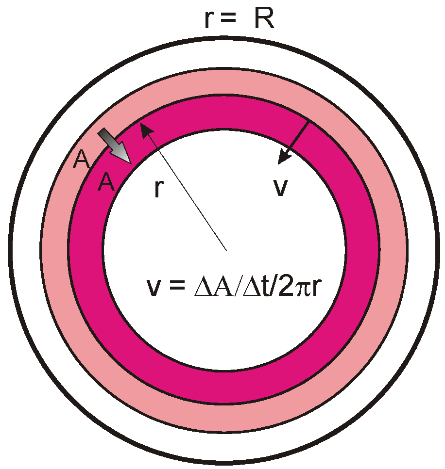
The basic idea of this paper is that fuel is drifting radially inwards or outwards, so that a standing breeding and burning wave is formed. This fuel drifting is considered theoretically as a continuous process, being regarded as a reasonable approximation of a discrete serial radial fuel shuffling in practice. Since the fuel and structure are not compressible, the fuel drift speed should be constrained by mass conservation. We take now the inward fuel drifting as an example, shown in Figure 2, although we will calculate the outward fuel drifting case in the 1-D case as well. It has to be pointed out that due to the fuel drifting a convective term will come from the original time derivative term, but this term is extremely small as already discussed in [9] and therefore has been neglected in Equation (1).
Figure 2.
Continuous model of radial inward fuel shuffling.

Fuel is fed in at and discharged at , where is the outer radius of the core and the inner radius. Usually the inner radius is zero, unless an external neutron source, a control rod, or a detector device is arranged at the center. Assuming the area of fuel sub-assemblies is loaded into the core or unloaded from the core in the time interval , due to the area conservation we have, at any r,
where is the shuffling speed of the fuel element area, which is a constant in the problem, and the sign stands for the outward and inward fuel motion, respectively. Equation (5) means that the local linear fuel drifting speed is equal to the fuel area speed divided by the local perimeter. The next important step is to derive the relationship between and . In the Lagrange coordinate it holds in general as:
where D/Dt is the material time derivative. It can be written as, if it is transformed to the Euler coordinate (the laboratory fixed coordinate):
This is the Lagrange-Euler coordinate transform. In the special form of , it becomes the Galilean transformation, as used for looking for the plane traveling wave [6,7,8,9,10,11,12,13,14]. But this is not the case here, since the wave drifting velocity is not constant. Further if we consider the asymptotic steady state, the time derivative becomes zero, we obtain:
This important relationship between and can also be obtained by a simple consideration. Since for the outward and inward fuel motions, respectively, and , we have:
This equation is a supplement to Equation (1) due to the fuel drifting and burn-up.
2.3. Boundary Conditions and Nonlinear Eigenvalue Problem
For the inward fuel drifting the fresh fuel is loaded at the core periphery and the spent fuel is discharged at the center. Therefore the neutron fluence is zero at the core outer periphery and maximal at the center. Reversely, for the outward fuel drifting, it is zero at the core center and maximal at the outer periphery. Together with the boundary condition for the neutron flux, the boundary conditions at [25] are written for the inward fuel drifting as:
Since there is no neutron source within the inner boundary of the core, the boundary condition at is simply a trivial Neumann boundary condition, i.e.,
Approximately, Equation (7) can be set as the trivial boundary conditions at the extrapolated boundary at as:
where is the so-called extrapolated distance, which is about 2.5 cm in our cases.
If the active core has a finite height in the axial direction, we have to set the boundary conditions at bottom and top ends of the core. We can set again the trivial boundary conditions at their extrapolated boundaries at and as:
where L is the length of the active core.
Formally we have completed the problem formulation with Equations (1), (4) and (6) and boundary conditions in Equations (7)–(10). This is a homogeneous system of equations, where the trivial solution of and always exists. Our interest is of course not the trivial solution, but the non-trivial solution. The non-trivial solution exists only at the so-called critical state, from the physical point of view. However, the problem with arbitrary parameters, such as material compositions, core dimensions, and fuel drifting speed, will not reach exactly the state of criticality on occasion. To solve the problem mathematically, an effective multiplication factor keff, which is a measure of the criticality, is introduced in Equation (1) in the usual manner as:
Here we can define the mean microscopic net neutron generation cross section f again under the influence of keff as:
which is a known function of , as is regarded as an eigenvalue. Up to now an eigenvalue problem is formulated with Equations (6)–(12). This eigenvalue problem is different from the classical one in the linear diffusion theory, because it is nonlinear, meaning is associated with a non-trivial solution of this nonlinear equation system. Moreover, is not only a measure of the criticality for the current state, but also for the asymptotic state. Physically it determines whether this fuel drifting under the certain neutron flux (power) can really reach the criticality in its asymptotic steady state.
3. 1-D Integration and Solutions
3.1. Integration
Now we try to solve first the above formulated problem in the 1-D case, where the core height is infinitely large and the solution is independent of z. Since the solution depends on the fuel motion direction, we have to treat the cases of the inward and outward fuel motions separately. Let us do it first for the inward fuel motion case. Equation (11) can be integrated once over , which gives:
Defining:
we have a complete set of equations as:
with boundary conditions:
Evaluating (15a) with the boundary condition in Equation (15c) at , we have:
where:
The boundary condition at has been already substituted into Equation (15a) and will be satisfied automatically by solving the equations. Moreover the boundary condition at is confined by Equation (16a). For solving equation system in Equation (15a,b), the boundary conditions of Equation (15d) are sufficient. The additional boundary condition in Equation (15c) or (16a) makes the equation system in Equation (15a,b) be overdetermined. This is the issue here in this eigenvalue problem. The condition in Equation (15c) or (16a) with Equation (16b) will be used to determine the eigenvalue keff. In mathematical words, keff has such a value, so that Equation (15c) or (16a) is satisfied by the non-trivial solution of Equation (15a,b) under condition in Equation (15d).
Similarly to the inward fuel motion, we have a set of equations for the outward fuel motion as:
with boundary conditions:
Substituting Equation (17d) into Equation (17a) we have:
where:
Equation (18a,b) are identical to Equation (16a,b), which will be used to determine keff. For solving this set of equations, similar arguments can be drawn as for Equations (15) and (16). To be clear, it is concluded that keff has such a value, so that Equation (17d) or (18a) is satisfied by the solution of Equation (17a,b) under condition in Equation (17c).
3.2. Dimensionalization and Dimensionless Characterizing Number
The nonlinear eigenvalue problem is different from the linear one. But since they come from similar physical problems, they have some common features. In the linear homogeneous eigenvalue problem, the amplitude of neutron flux is a free parameter, which is usually fixed, e.g., by the total power or the maximal power density. Therefore everything can be normalized by its amplitude. In the nonlinear burn-up problem here, the solution is certainly dependent on the amplitude. However, there is a certain parameter, a combination of the flux amplitude and other quantities, with which the solution is invariant. To find this parameter is the purpose of these analyses. Most of such mathematically invariant parameters are physically dimensionless parameters, like the well-known Reynolds number, Mach number and so on in fluid mechanics. Under the same values of such numbers the solutions are similar. This is the so-called similarity law, which is some kind of invariance. We will see here, there is also such an important dimensionless characterizing number in this problem.
The neutron net generation cross section f has the dimension of barn, the neutron flux 1/(barn s) and the neutron fluence 1/barn. Therefore, the function g is dimensionless. Usually the neutron flux is normalized by its maximal value or the average value, or even in particular for this boundary value problem by its boundary value or . Anyway such a typical value can be noted as and the non-dimensional flux as . The neutron fluence can be non-dimensionalized by multiplying it by a typical value of microscopic cross section. In this particular fuel drifting burn-up problem, a typical value for the fluence is , where is the linear fuel drifting velocity at , i.e., .
Thus, we use , , to normalize variables and parameters:
All variables with superscript * are dimensionless. It is recognized immediately that the solution is invariant with the ratio of . Moreover the quantity:
plays an important role in this kind of burn-up problem. Any kind of microscopic cross section including f can be normalized by this quantity:
or a typical value of non-dimensionalized fluence, e.g., the maximal or average fluence:
can be the dimensionless “characterizing number” in this problem.
Since is already dimensionless, it needs only a variable transformation, i.e., as function of , . Then, for the inward fuel motion, Equation (15a,b) with boundary conditions in Equation (15c,d) become:
with boundary conditions:
The constraint condition in Equation (16a) becomes:
This is an important constraint in this problem. The normalization of with its value at is suitable for the mathematical problem, since it has simplified the mathematical formulation of the problem. However, it is not common in the nuclear community and not usual for practical purposes, because the maximal value of the flux can be much larger than the boundary value. A renormalization with the average value or maximal value can be easily done, as the solution is known. We present our results also with this renormalization.
For the outward fuel motion, the same normalization procedure can be carried out. For the sake of convenience, we omit it here.
We take the following data from a typical SFR as applied in [13] for our 1-D examples here. The core outer radium is R = 150 cm, the inner radius is zero (r0 = 0 cm) and the maximal neutron flux is 3 × 1015 cm−2·s−1. The used parameters are shown in Table 1.

| Parameter | Value | Parameter | Value |
|---|---|---|---|
| R | 150 cm | d | 2.52 cm |
| r0 | 0 cm | NHM,0 | 1.221 × 1022 cm−3 |
| D | 1.260 cm | ϕmax | 3 × 1015 cm−2·s−1 |
3.3. Solution of Inward Fuel Drifting
As discussed before the solution of the nonlinear stationary wave problem is invariant with the ratio of or . The solution is always associated with the value of and the obtained value of keff. This implies that the neutron flux can be changed to any value, but the fuel drift speed should be changed correspondingly, so that does not change and the solution holds. The problem can be solved as described in the following. For a certain fixed value of and a guessed value of keff, the problem in Equation (15a,b) with boundary condition in Equation (15d) can be solved numerically. This preliminary solution will not satisfy the condition in Equation (15c) or (16a), but based on this solution we can change keff step by step until the condition is satisfied. The final keff and its associated solution are true. Only those solutions with keff slightly above unity are physically useful for establishing a critical state. Table 2 shows calculated results of four variation cases.
| Variable | Case 1 | Case 2 * | Case 3 | Case 4 |
|---|---|---|---|---|
| (barn cm) | 443.2 | 886.4 | 2659.2 | 8864 |
| (barn cm) | 22.76 | 28.58 | 40.23 | 63.56 |
| (barn cm) | 15.00 | 16.37 | 14.28 | 12.54 |
| keff | 0.96685 | 1.00376 | 1.03119 | 1.01414 |
| Flux peaking factor | 1.517 | 1.746 | 2.804 | 5.069 |
| Boundary factor | 19.48 | 31.01 | 66.43 | 139.5 |
| Power peaking factor | - | 1.91 | - | |
| Burn-up (at%) | - | 55.3 | - |
* Case 2 satisfies the criticality requirement; therefore this column is highlighted with bold format and more physical parameters are evaluated.
As shown in Table 2, as the drift speed increases from Cases 1 to 4 in terms of the average neutron flux, the flux peaking factor increases and the maximal fluence (that in the discharged fuel) decreases monotonically. But the ratio of the drift speed to the maximal flux, , becomes maximal in Case 2 and the effective multiplication factor keff in Case 3. As suggested by one of reviewers, we show the neutron flux and fluence distributions with the drift speed variation in Figure 3, where the monotonic shape change of the neutron flux and fluence with the variation of drift speed is clear to see. For a fixed average flux, if is very large or very small, keff should be quite low. Therefore there must be a maximum point of keff in a suitable speed range. This is Case 3. Additionally, since the flux peaking factor is increasing more quickly than , must has a maximum point that is Case 2.
Figure 3.
Distributions of neutron flux and fluence in the case of radial inward fuel shuffling with variation in Table 2.
Figure 3.
Distributions of neutron flux and fluence in the case of radial inward fuel shuffling with variation in Table 2.
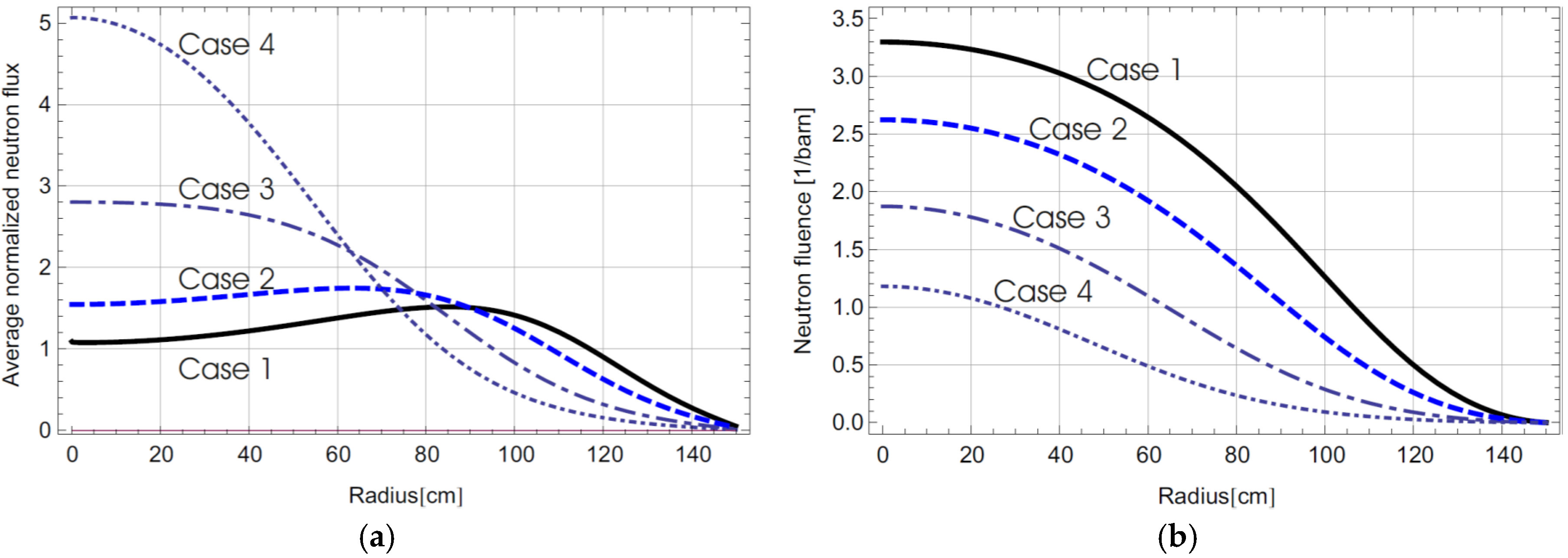
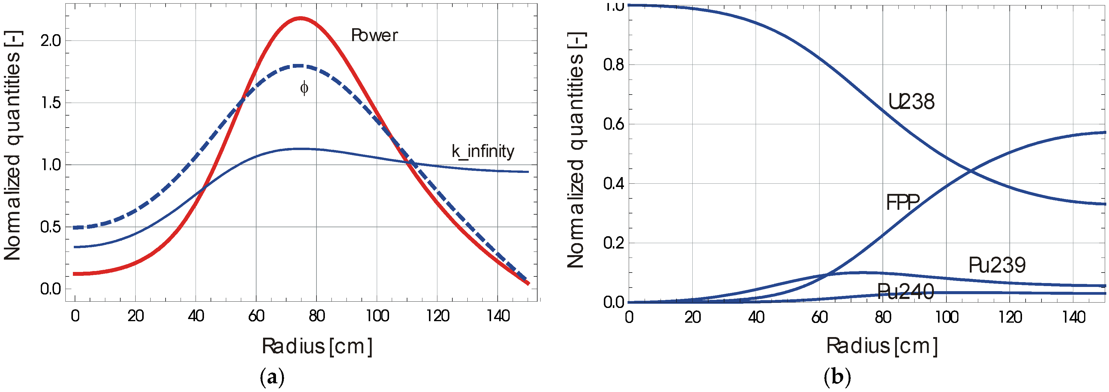
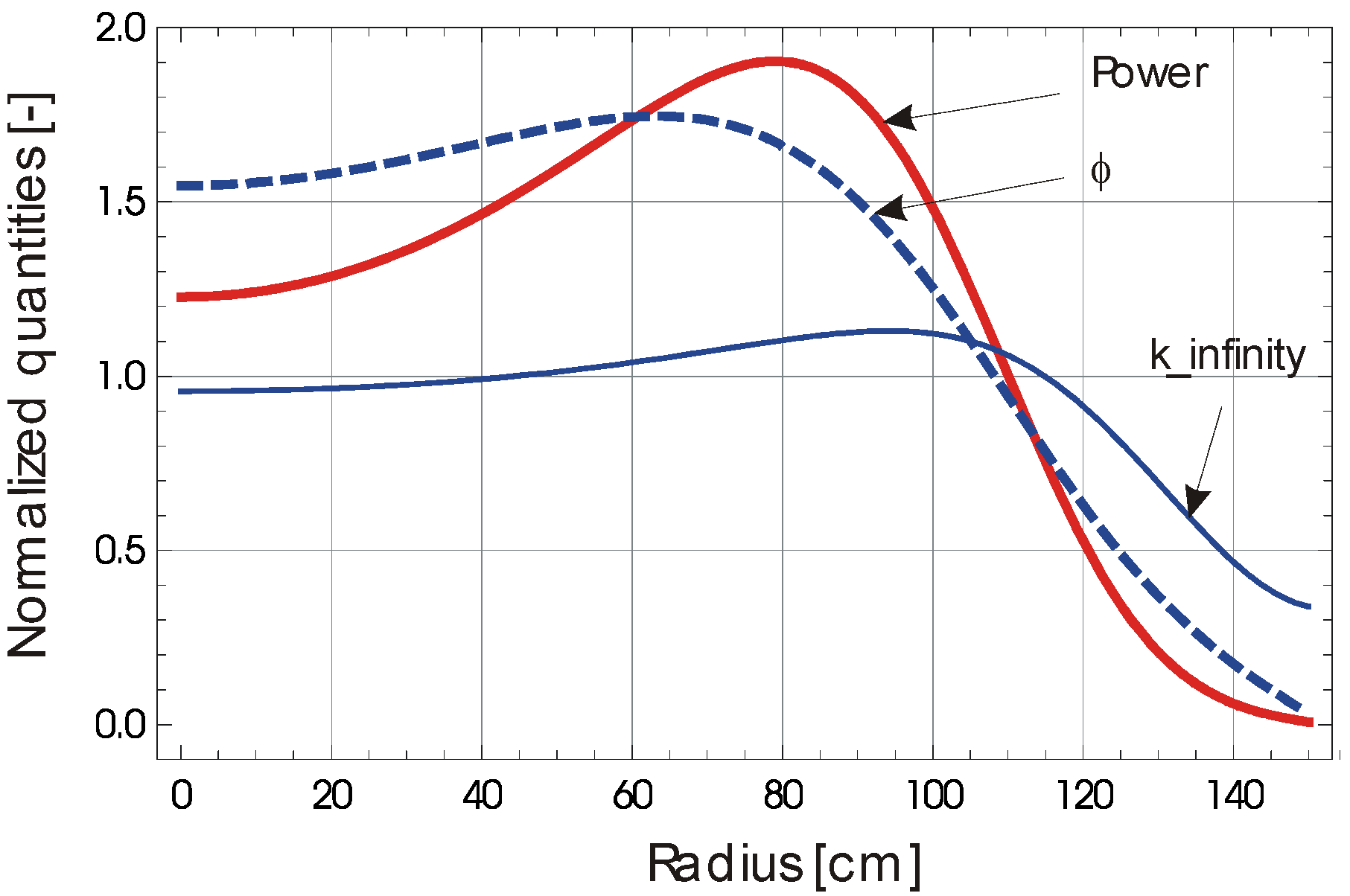
Case 2 in Table 2 fits more or less to our purpose, where barn cm and keff = 1.00376, associated with and barn. Therefore the result in this case will be presented as follows. Since , and can be calculated as cm−2·s−1 and cm/s (1.548 cm/year) for cm−2·s−1. This implies that the total time needed by the fuel for moving from the periphery to the center is = 48.4 years. The radial distributions of average value normalized neutron flux and power density and are shown in Figure 4 and the associated neutron fluence in Figure 3, the Case 2 curve. The power peaking factor is 1.91 in this case, which is slightly higher than that for the flux of 1.75. The maximal neutron fluence is 2.6236 barn−1 and the correspondingly achieved burn-up is 55.3%. The power shape across the diameter looks somehow like the letter M, which is qualitatively similar to that presented by TerraPower, e.g., in [5].
Figure 4.
Distributions of power, neutron flux and k_infinity () in the case of radial inward fuel shuffling of Case 2 in Table 2.
Figure 4.
Distributions of power, neutron flux and k_infinity () in the case of radial inward fuel shuffling of Case 2 in Table 2.
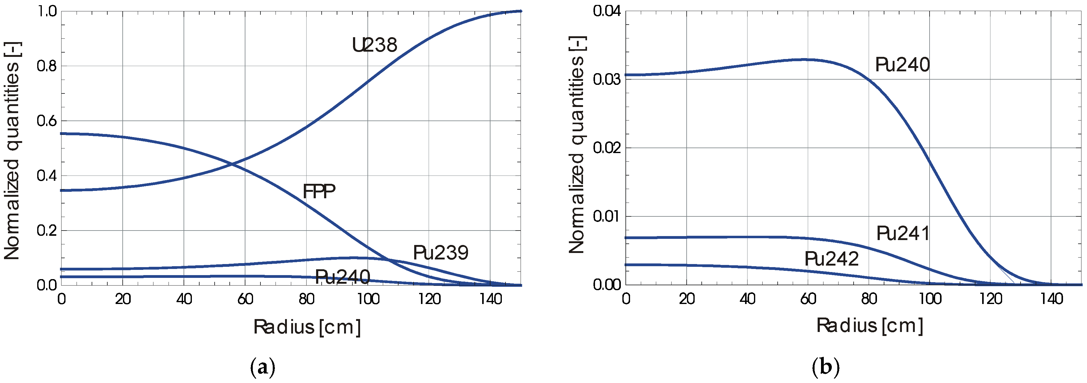
The burn-up calculations in this case are based on our simplified model [13]. The main actinide isotopes are shown in Figure 5. As can be seen there, during the radial inward fuel shuffling 238U decreases monotonously and 239Pu increases first, reaches a maximum of about 10% and then decreases. The fission product pairs (FPPs) and other Pu isotopes with higher mass numbers are produced from zero at the outer radius. The neglect of radioactive decay processes can lead to some errors for higher Pu isotopes shown in the right plot of Figure 5 with an enlarged scale. For instance in reality a large of amount 241Pu would have decayed to 241Am as the fuel is discharged at the core center. Thus the curve for 241Pu in Figure 5 is representative for the sum of 241Pu and 241Am.
Figure 5.
Distributions of main actinide isotopes in the case of radial inward fuel shuffling of Case 2 in Table 2.
Figure 5.
Distributions of main actinide isotopes in the case of radial inward fuel shuffling of Case 2 in Table 2.
3.4. Solution of Outward Fuel Drifting
The outward fuel drifting can be calculated as well in a similar way. The natural normalization of ϕ in this case is to use the value at the center ϕ0, i.e., . Without further detailed explanation we just show the corresponding result. Through the variation we obtain the highest keff of about 0.9821. This means that this fuel drifting (shuffling) scheme cannot reach criticality in this core/fuel configuration under current cross section data. The reason for it is as follows: The fresh fuel with quite low kinf starts from the central region, where the flux is usually high, implying neutron importance is high, and irradiated fuel with higher kinf is located in the peripheral region, where the flux is usually lower. Therefore the neutron importance and kinf is worse matched in the outward fuel shuffling case than in the inward case. But the core at the subcritical level might be driven by an accelerator driven system or the core can become critical by adding fissile material to the fresh fuel. Therefore, also for the sake of comparison with inward shuffling, we would like to present the result. and can be calculated as cm−2·s−1 cm/s (1.442 cm/year) and the total time t = 52 years. The radial distributions of average value normalized neutron flux and power density and are shown in Figure 6a and the main actinide isotopes are shown in Figure 6b. The maximal neutron fluence is 2.736 barn−1 and the correspondingly achieved burn-up is 57.2%. The power shape across the diameter is like the letter M as well but with a much deeper central dip. The power peaking factor is about 2.20 in this case, which is higher than that in the case of inward fuel drifting. The approximate analytic solution in [19] shows a similar M shape to ours.
Figure 6.
Distributions of (a) power, neutron flux and and (b) main actinide isotopes in the case of radial outward fuel shuffling.
Figure 6.
Distributions of (a) power, neutron flux and and (b) main actinide isotopes in the case of radial outward fuel shuffling.

4. 2-D Numerical Solution
4.1. Data Preparation
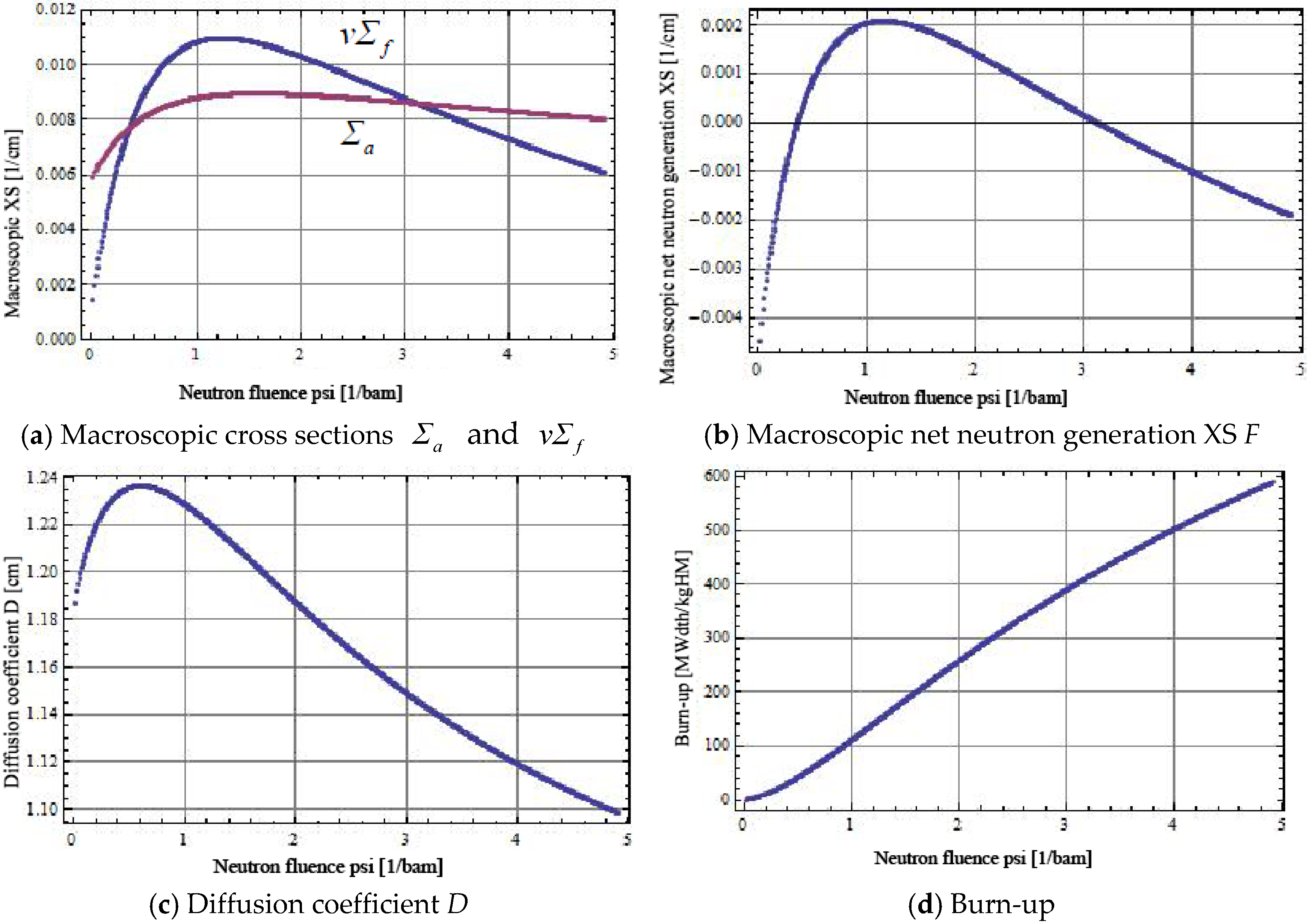
In the 2-D case, instead of solving the simplified burn-up equations like in [13], we directly use the data of the macroscopic cross sections, which are obtained with a cell burn-up calculation by the ERANOS code [26]. The fuel, coolant, and steel volume fractions are 50%, 30%, and 20%, respectively. Metallic fuel is chosen for this case because of its high density that is in favor of breeding. The theoretical densities of metallic fuel, Na coolant, and steel are taken as 19.1 g/cm3, 0.83 g/cm3, 7.7 g/cm3, respectively. The initial isotopic atom number densities of fuel, coolant and steel can be calculated for ERANOS input accordingly. The irradiation neutron flux used in the neutronic calculation is constant and about 2.5 × 1015 cm−2·s−1. Figure 7 presents results of , , F, and D and the burn-up as functions of ψ. The burn-up is almost linear with ψ in the considered fluence range. It should be mentioned that pure metallic fuel with the density of 19.1 g/cm3 is used in this paper, which is in favor of breeding and the asymptotic keff level, but would not be so realistic for a high burn-up. Usually the zirconium alloyed metallic fuel with the density of 15.8 g/cm3, see e.g., [27], were used.
Figure 7.
Macroscopic cross sections of , , and and the burn-up as functions of .

4.2. Unsteady Problem Formulation
The steady state eigenvalue problem can be solved through time stepping iteration of its associated unsteady problem. The unsteady problem can be formulated as:
where τ is the neutron generation time normalized time, i.e., , and the neutron fluence is given as, for the inward fuel drifting,
It is necessary to state that we only consider inward fuel movements in 2-D cases, since the 1-D results have shown that the inward case is better than the outward one with respect to keff.
The reactivity defined as:
can be evaluated by the solution of Equation (25a) due to its self-adjoint property for the one energy group treatment as:
The relationship between keff and is given here as:
The unsteady in Equation (25a) together with Equation (25b) under boundary conditions in Equations (8)–(10) can be solved directly by Mathematica.
4.3. Normalization and Time Stepping Iteration
Before we get the iteration solution, we need to normalize or non-dimensionalize the equations similarly to the 1-D case. We use the radius R, the maximal and the fuel drifting speed at as basic dimensional variables. Then the following scales can be derived for the current problem,
where is the HM atom number density of the fresh fuel, i.e., of 238U at .
In the following, we just solve normalized equations. For the sake of simplicity, we use the same symbols for non-dimensional variables as those for the dimensional ones. With a rough approximation of the asymptotic state as initial value that can be obtained by the 1-D radial solution and the cosine form in the axial direction we start our iteration procedure. As the neutron flux is given as an initial guess, we can have its “asymptotical” associated neutron fluence from Equation (25b). Then with this neutron fluence, we can solve Equation (25a) by certain time iteration steps to obtain a new neutron flux and its associated reactivity. This iteration procedure in step n, as formulated below, can go on until the solution is convergent.
“Convergent” means that is sufficiently small everywhere, but it implies also that is a steady state solution with the associated keff.
4.4. Numerical Results
We consider the cylindrical core dimension of R = 150 cm and L = 200 cm, in which the extrapolation length d on the core outer boundary has been already included for this case. Again, we do the variation of similarly to 1-D cases. The main parameters in the variation are shown in Table 3. is monotonically increasing from Cases 1 and 3 while the fluence is decreasing. The average burn-ups deduced from Figure 7d are 346 MWd/kgHM, 233 MWd/kgHM and 121 MWd/kgHM, and the maximal burn-ups 488 MWd/kgHM, 388 MWd/kgHM and 271 MWd/kgHM for Cases 1–3, respectively. It is interesting to observe that Case 1, shown in Figure 8, has the largest burn-up and the smallest peaking factor, while Case 3, shown in Figure 9, has the smallest burn-up and the largest peaking factor. Case 2 has the largest keff. The large peaking factor in Case 3 does not imply this case is not realistic in practice. If we look at its power distribution shown in Figure 9d, we recognize that a large part of core in the peripheral zone has nearly zero power, which can be regarded as a blanket region, as common in conventional fast breeder reactor designs. If this region is excluded, the peaking factor will be reduced to a realistic value of about 4.
| Variable | Case 1 | Case 2 | Case 3 |
|---|---|---|---|
| in (barn cm) | 11.695 | 10.455 | 6.796 |
| in (barn cm) | 28.34 | 41.18 | 70.34 |
| keff | 1.02230 | 1.06208 | 1.04664 |
| in (1/barn) | 3.8576 | 2.9857 | 2.0912 |
| in (1/barn) | 2.6466 | 1.8211 | 1.0664 |
| Flux peaking factor | 2.423 | 3.939 | 10.35 |
| Flux peak position | 0.581 | 0.303 | 0 |
| Power peaking factor | 2.745 | 4.345 | 12.20 |
| Power peak position | 0.665 | 0.385 | 0 |
It is interesting to notice that one characteristic parameter, namely the ratio of the drift speed to the maximal flux, , shown in the first line in Table 3, decreases monotonically from Case 1 to Case 3, but another parameter, namely , in the second line in Table 3, increases. As we compare 2-D cases with 1-D ones, we find surprisingly that the values of in 2-D cases in Table 3 are quite similar to those in 1-D cases in Table 2, while values are lower than those in Table 2. This means that it is quite suitable to choose the average flux as the reference value for comparison of 1-D and 2-D cases. The reason for higher values of in 2-D cases is the higher peaking factors there because of its additional axial neutron leakage.
Herewith we want to insert a comment on keff results. All the values of keff shown in Table 3 are slightly above unity. This might not be absolutely true, because our model is not so accurate for predicting the “prompt” value of keff. It is even much more a challenge in general to accurately predict the asymptotic value of keff for any existing code. Small errors in microscopic data, which do not have significant effects on the prompt keff of a core with quite fresh or short-time irradiated fuel, can result in a significant error in the asymptotic keff, since the error is accumulated through a long time process of e.g., 50 years fuel burn-up. But this does not mean the calculated results are useless. The relative tendency of the asymptotic keff is important for determining the current parameter of . The error in the asymptotic keff due to existing uncertainties should be compensated in reality by control rods, which can regulate the reactivity at the current time. In the authors’ opinion, such control rods are needed in TWR designs, contrarily to the opinion of no need of control rods in TWR, which was often held in this community in the past.
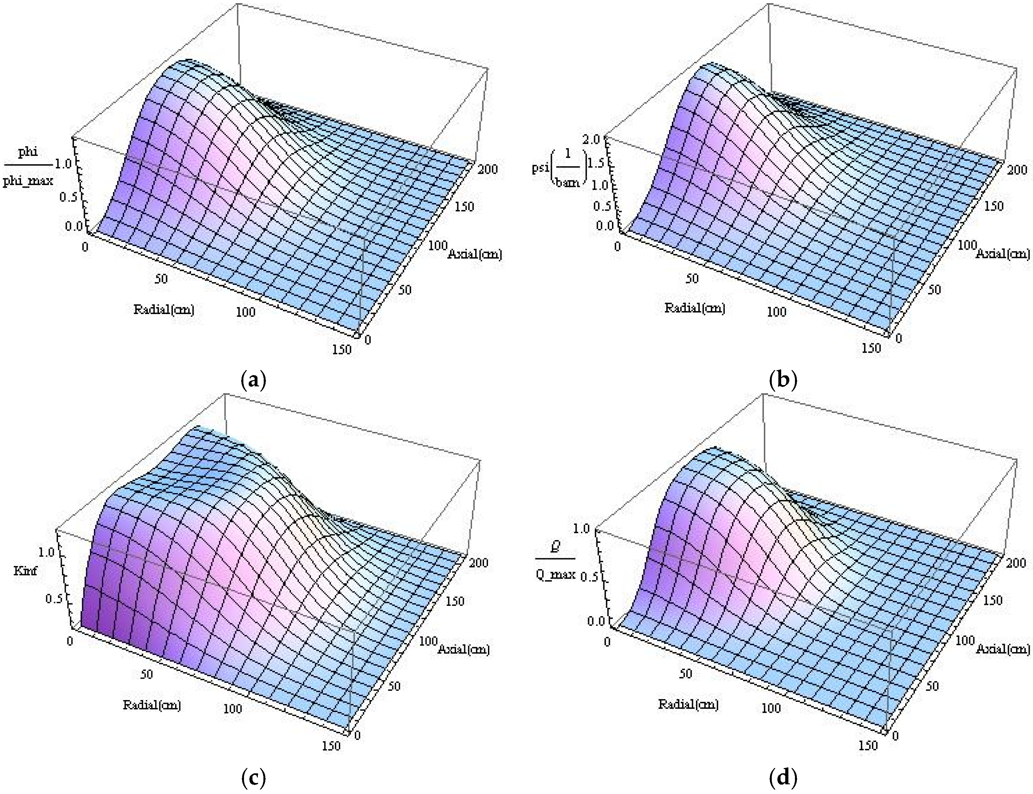
Calculated results of Cases 1 and 3 in Table 3 are presented with distributions of neutron flux, fluence, kinf and power in Figure 8 and Figure 9, respectively. While the fuel drifting speed is increasing from Cases 1 Case 3, the power peak position shifts from about 2/3 of radius to the center and the power shape changes from a sickle-shaped pattern to one with a mono peak at the core center. Since the neutron flux is higher in the mid-core than in the upper and lower parts of the core and consequently the burn-up or neutron fluence is higher in the mid-core, if the fuel drift is sufficiently slow like in Case 1 as shown in Figure 8, the maximal power density is located off the center, e.g., roughly in the radial range 90–100 cm away from the core center in this special case, and a depression around the core center, e.g., axially between 50 cm and 150 cm, is formed. As consequence the power distribution becomes sickle-shaped, which is similar to the axial wave pattern [11,20]. If the fuel drift is relatively quick, so that the position of maximal kinf is close to or at the center, the power shape is of course center-peaked as in Case 3 as shown in Figure 9.
Figure 8.
Distributions of neutron flux ϕ, fluence ψ, infinity multiplication factor kinf and the normalized power density in Case 1 in Table 3. (a) Neutron flux; (b) neutron fluence; (c) infinity multiplication factor; (d) power density.
Figure 8.
Distributions of neutron flux ϕ, fluence ψ, infinity multiplication factor kinf and the normalized power density in Case 1 in Table 3. (a) Neutron flux; (b) neutron fluence; (c) infinity multiplication factor; (d) power density.

Figure 9.
Distributions of neutron flux ϕ, fluence ψ, infinity multiplication factor kinf and the normalized power density in Case 3 in Table 3. (a) Neutron flux; (b) neutron fluence; (c) infinity multiplication factor; (d) power density.
Figure 9.
Distributions of neutron flux ϕ, fluence ψ, infinity multiplication factor kinf and the normalized power density in Case 3 in Table 3. (a) Neutron flux; (b) neutron fluence; (c) infinity multiplication factor; (d) power density.

It should be mentioned that the axial burn-up distribution in the discharged fuel assembly is similar to the shape of the fluence at r = 0, because the burn-up is almost linearly proportional to the fluence. It can be seen from Figure 8b and Figure 9b that the axial burn-up distribution in Case 1 is flatter than in Case 3.
5. Conclusions
From the mathematical physics point of view, the TWR concept with serial radial fuel shuffling is studied in this paper. The one-group diffusion model coupled with simplified burn-up models and a significantly simplified treatment of fission products is applied and the radial fuel shuffling is modeled approximately by continuous fuel drifting. UOX and metallic fuels with pure 238U are considered as fresh fuel compositions. Asymptotically stationary wave solutions with associated eigenvalues keff in 1-D cases are obtained successively by analytic and numerical integrations for certain ratios of neutron flux and fuel drift speed for both inward and outward drifting. The inward fuel drifting has a better TWR capability than the outward one, where the maximal achieved asymptotic keff in the inward drifting case is significantly higher than that in the outward case. The 2-D eigenvalue problem is solved numerically by the pseudo time stepping iteration scheme. The asymptotically stationary 2-D wave solutions are obtained together with associated eigenvalues keff for several fuel inward drifting speeds. Associated distributions of the neutron flux, the neutron fluence, the infinity multiplication factor kinf, and the normalized power density are presented for the inward fuel drifting motion for showing 2-D and drifting speed effects. The dimensional analysis and the numerical results show that the dimensionless parameter is a characterizing number in this problem.
Acknowledgments
The authors thank our colleague Andrei Rineiski for his valuable discussions and comments and our former colleague Dalin Zhang, now working at Xi’an Jiaotong University, for providing one group macroscopic data obtained numerically during her stay at KIT. They would like to also thank the three reviewers of this paper for their very helpful and constructive comments.
Author Contributions
Xue-Nong Chen did the numerical modelling and wrote the paper. Edgar Kiefhaber reviewed and edited the manuscript. All authors read and approved the manuscript.
Conflicts of Interest
The authors declare no conflict of interest.
References
- Hejzlar, P.; Petroski, R.; Cheatham, J.; Touran, N.; Cohen, M.; Truong, B.; Latta, R.; Werner, M.; Burke, T.; Tandy, J.; et al. TerraPower, LLC Traveling wave reactor development program overview. Nucl. Eng. Technol. 2013, 45, 731–744. [Google Scholar] [CrossRef]
- Traveling Wave Reactor. Available online: http://en.wikipedia.org/wiki/Traveling_wave_reactor (accessed on 30 November 2015).
- Weaver, K.D.; Ahlfeld, C.; Gilleland, J.; Whitmer, C.; Zimmerman, G. Extending the nuclear fuel cycle with traveling-wave reactors. In Proceedings of the Global 2009, Paris, France, 6–10 September 2009.
- Ellis, T.; Petroski, R.; Hejzlar, P.; Zimmerman, G.; McAlees, D.; Whitmer, C.; Touran, N.; Hejzlar, J.; Weaver, K.; Walter, J.C.; et al. Traveling-Wave Reactors: A truly sustainable and full-scale resource for global energy needs. In Proceedings of the ICAPP’10, San Diego, CA, USA, 13–17 June 2010.
- Gilleland, J. The History of TerraPower and Traveling Wave Reactor Development, 2006 to Present. In Proceedings of the INES-3, Tokyo, Japan, 31 October–3 November 2010.
- Feoktistov, L.P. Neutron-fissioning wave. Rep. Acad. Sci. USSR 1989, 309, 864–867. [Google Scholar]
- Teller, E.; Ishikawa, M.; Wood, L. Completely automated nuclear reactors for long-term operation, Part I. In Proceedings of the Frontiers in Physics Symposium, American Physical Society and the American Association of Physics Teachers Texas Meeting, Lubbock, TX, USA, 26–28 October 1995.
- Teller, E.; Ishikawa, M.; Wood, L.; Hyde, R.; Nuckolls, J. Completely automated nuclear reactors for long-term operation, Part II. Toward a concept-level point-design of a high-temperature, gas-cooled central power station system. In Proceedings of the ICENES’96, Obninsk, Russia, 24–28 June 1996; pp. 151–158.
- Van Dam, H. Self-stabilizing criticality waves. Ann. Nucl. Energy 2000, 27, 1505–1521. [Google Scholar] [CrossRef]
- Seifritz, W. Solitary burn-up waves in a multiplying medium. Kerntechnik 2000, 65, 261–264. [Google Scholar]
- Sekimoto, H.; Ryu, K.; Yoshimura, Y. CANDLE: The new burnup strategy. Nucl. Sci. Technol. 2001, 139, 306–317. [Google Scholar] [CrossRef]
- Chen, X.-N.; Kiefhaber, E.; Maschek, W. Fundamental burn-up mode in a pebble-bed type reactor. Prog. Nucl. Energy 2008, 50, 219–224. [Google Scholar] [CrossRef]
- Chen, X.-N.; Kiefhaber, E.; Zhang, D.; Maschek, W. Fundamental solution of nuclear solitary wave. Energy Convers. Manag. 2012, 59, 40–49. [Google Scholar] [CrossRef]
- Chen, X.-N.; Zhang, D.; Maschek, W.; Schulenberg, T. Solitary breeding/burning waves in a supercritical water cooled fast reactor. Energy Convers. Manag. 2010, 51, 1792–1798. [Google Scholar] [CrossRef]
- Zhang, D.; Chen, X.-N.; Gabrielli, F.; Rineiski, A.; Maschek, W.; Schulenberg, T. Numerical studies of nuclear traveling waves in a supercritical water cooled fast reactor. Prog. Nucl. Energy 2011, 53, 806–813. [Google Scholar] [CrossRef]
- Osborne, A.G.; Deinert, M.R. Comparison of neutron diffusion and Monte Carlo simulations of a fission wave. Ann. Nucl. Energy 2013, 62, 269–273. [Google Scholar] [CrossRef]
- Chen, X.-N.; Zhang, D.; Maschek, W. Theoretical modeling of radial standing wave reactor. Trans. Fusion Sci. Technol. 2012, 61, 275–280. [Google Scholar]
- Zhang, D.; Chen, X.-N.; Flad, M.; Rineiski, A.; Maschek, W. Theoretical and numerical studies of TWR based on ESFR core design. Energy Convers. Manag. 2013, 72, 12–18. [Google Scholar] [CrossRef]
- Seifritz, W. A standing wave reactor by continuous radial fuel shuffling. Kerntechnik 2012, 77, 68–71. [Google Scholar]
- Chen, X.-N.; Maschek, W. Transverse buckling effects on solitary burnup waves. Ann. Nucl. Energy 2005, 32, 1377–1390. [Google Scholar] [CrossRef]
- Fomin, S.P.; Mel’nik, Yu.P.; Pilipenko, V.V.; Shul’ga, N.F. Initiation and propagation of nuclear burning wave in fast reactor. Prog. Nucl. Energy 2008, 50, 163–169. [Google Scholar] [CrossRef]
- Rusov, V.D.; Linnik, E.P.; Tarasov, V.A.; Zelentsova, T.N.; Sharph, I.V.; Vashchenko, V.N.; Kosenko, S.I.; Beglaryan, M.E.; Chernezhenko, S.A.; Molchinkolov, P.A.; et al. Traveling wave reactor and condition of existence of nuclear burning soliton-like wave in neutron-multiplying media. Energies 2011, 4, 1337–1361. [Google Scholar] [CrossRef]
- Rusov, V.D.; Tarasov, V.; Sharph, I.V.; Vashchenko, V.N.; Linnik, E.P.; Zelentsova, T.N. On some fundamental peculiarities of the traveling wave reactor. Sci. Technol. Nucl. Install. 2015, 2015. [Google Scholar] [CrossRef]
- Zheng, M.; Tian, W.; Chu, X.; Zhang, D.; Qiu, S.; Su, G. Preliminary design study of a board type radial fuel shuffling sodium cooled breed and burn reactor core. Nucl. Eng. Des. 2014, 278, 679–685. [Google Scholar] [CrossRef]
- Glasstone, S.; Edlund, M.C. The Elements of Nuclear Reactor Theory; D. Van Nostrand Company, Inc.: Princeton, NJ, USA; London, UK, 1952. [Google Scholar]
- Rimpault, G.; Plisson, D.; Tommasi, J.; Jacqmin, R.; Rieunier, J.M.; Verrier, D.; Biron, D. The ERANOS code and data system for fast reactor neutronic analyses. In Proceedings of the PHYSOR 2002, Seoul, Korea, 7–10 October 2002.
- Pahl, R.G.; Porter, D.L.; Lahm, C.E.; Hofman, G.L. Experimental studies of U-Pu-Zr fast reactor fuel pins in the experimental breeder reactor-II. Metall. Mater. Trans. A 1990, 21, 1863–1870. [Google Scholar] [CrossRef]
© 2015 by the authors; licensee MDPI, Basel, Switzerland. This article is an open access article distributed under the terms and conditions of the Creative Commons by Attribution (CC-BY) license (http://creativecommons.org/licenses/by/4.0/).
Share and Cite
MDPI and ACS Style
Chen, X.-N.; Kiefhaber, E. Asymptotic Solutions of Serial Radial Fuel Shuffling. Energies 2015, 8, 13829-13845. https://doi.org/10.3390/en81212398
AMA Style
Chen X-N, Kiefhaber E. Asymptotic Solutions of Serial Radial Fuel Shuffling. Energies. 2015; 8(12):13829-13845. https://doi.org/10.3390/en81212398
Chicago/Turabian StyleChen, Xue-Nong, and Edgar Kiefhaber. 2015. "Asymptotic Solutions of Serial Radial Fuel Shuffling" Energies 8, no. 12: 13829-13845. https://doi.org/10.3390/en81212398