Article

Transient Oscillations Analysis and Modified Control Strategy for Seamless Mode Transfer in Micro-Grids: A Wind-PV-ES Hybrid System Case Study

1
College of Automation, Nanjing University of Posts and Telecommunications, Nanjing 210023, China
2
School of Computer Science, University College Dublin, Dublin 4, Ireland
3
Earth Institute, University College Dublin, Dublin 4, Ireland
*
Author to whom correspondence should be addressed.
Energies 2015, 8(12), 13758-13777; https://doi.org/10.3390/en81212396
Submission received: 20 August 2015 / Revised: 30 November 2015 / Accepted: 30 November 2015 / Published: 4 December 2015

Abstract

:
With the rapid development of the micro-grid associated with new and clean energies, the smooth switching between grid-connected and islanded operation modes of the micro-grid is a key issue that needs to be addressed urgently. In traditional solutions, V/f (Voltage/frequency) control is adopted for the master micro sources when the micro-grid works in islanded mode, while PQ (real and reactive power) control is adopted when in grid-connected mode. However, when the two controllers switch when mode transfer occurs, transient oscillations usually occur and thereafter the dynamic response will be degraded. This paper considers an archetypical micro-grid with Wind-PV-ES (Wind, Photovoltaic and Energy Storage) hybrid system, which forms the basis of our case study. The underlying reason for such transient oscillation is analyzed in this paper. Thereafter a modified control strategy for seamless mode transfer is designed and implemented. An improved PQ control method is designed by which the output of the PQ controller always synchronously tracks the output of the V/f controller for micro-grid switches from islanded mode to grid-connected; furthermore, a dq rotating coordinate synchronization based V/f control method is proposed for transition from grid-connected mode to islanded mode. Finally, experiments and analysis are undertaken on some basic and important operating cases; the results in our case study indicate that the modified control strategy is effective in dominating the micro-grid during mode transfer and thus yielding significantly better performances.

1. Introduction

In recent years, micro-grids, as the low-voltage distribution systems, have captured considerable attention due to the many advantages they afford including enhanced reliability, scalability, and flexible control when compared with large centralized power systems. The micro-grid consists of distributed energy resources (DERs) and controllable loads, where DERs typically include a variety of distributed generation (DG) units such as wind turbines (WTs), photovoltaics (PVs), and energy storage (ES) units such as batteries [1]. As the archetypical micro-grid architecture, Wind-PV-ES hybrid systems make use of complementary features of wind and solar energy in order to reduce storage capacity and deliver a reliable and consistent service. As a result of these features, the micro-grid can be operated in either grid-connected mode to exchange power with the main power grid, or islanded mode to supply local loads when the main power grid is not available [2]. Accordingly, operational control of micro-grids is a major area of research, which primarily embodies the following four topics: (1) the regulation of power flow in the micro-grid and the decoupling control of active and reactive power; (2) the control of each DG interface voltage to maintain voltage stability; (3) the rapid response of DGs to supply the local power load in islanded mode; (4) the seamless transfer between grid-connected and islanded operation modes, which is one of the most important but difficult scenarios which must be routinely handled within real time applications [3,4].
Micro-grid control may be implemented under either the master-slave or peer-peer control architecture. The widely adopted master-slave control mechanism means that all the DGs within the micro-grid adopt PQ (real and reactive power) control in grid-connected mode, but in islanded mode, one or several master DGs should be changed to operate under V/f control so as to maintain voltage and frequency stability [5]. PQ control means that the DG is controlled to output maximum power or specified power according to actual conditions. PQ control is designed to maximize the utilization of renewable energy, so it is suitable for intermittent power sources [5], such as wind turbine and PV. This kind of energy source often operates at the maximum power point; the active power of which usually is not continuously controllable. As a consequence, the control of such energy sources is placed under a PQ control method irrespective of whether the micro-grid is operating under islanded mode or grid-connected mode. Conversely, the active and reactive power of energy storage units can be adjusted, thus the energy storage system becomes the “master” power of the micro-grid ensuring the balance between energy generation and consumption especially during large fluctuations in load or generation capacity. Such master power operates under PQ control when the micro-grid is in grid-connected mode and V/f control when in islanded mode; it in effect offers frequency and voltage support for the micro-grid [6].
Most distributed energy sources are connected to the micro-grid through interface inverters. Therefore, the control performance of the interface inverter is the focal point in maintaining the stability of the micro-grid. Various control management and operation strategies for micro-grid have been proposed in the past decades [6,7,8,9,10,11,12,13,14,15,16,17,18,19,20,21,22,23,24]. Several PQ controlled micro-grids were developed in [7,8,9], where the interface inverter is equivalent to a controlled current source. However, such inverter cannot run in isolation due loss of support of voltage and frequency when the micro-grid is operating in islanded mode [10]. The interface inverter in V/f controlled micro-grid can be equivalent to a controlled voltage source; voltage and frequency stability can be supported by the master power source. However, the V/f control is not suitable for applications in grid-connected mode. The operating requirements of the micro-grid cannot thus be met with merely a single control strategy. In other words, the control method for the master power source ought to be changed to reflect micro-grid operating mode changes. The problem, yet to be solved, is how to realize this seamless mode transfer, namely, how to maintain the voltage phase, the amplitude and the frequency of the micro-grid to ensure it does not change abruptly at the moment of transfer.
In the case of the grid-connecting process, synchronization between micro-grid and main power grid is the most significant issue. To limit the switching transient and enables a smooth mode transfer from islanded to grid-connected mode, a modified voltage based droop control method was proposed in [11]. The modified voltage based droop control is primarily to synchronize the voltage of a specified DG unit with the main power grid voltage. To achieve high penetration depth of renewable sources into the main power grid, a renewable energy-based dc micro-grid with hybrid energy storage is investigated and a novel system operation strategy is proposed in [12]. Transition from grid-connected to islanded modes of operation is likely to cause large mismatches between generation and load. Katiraei studied system behavior after islanding and used a control reconfiguration to stabilize the system [13]. To mitigate voltage and frequency variations, strategies to manage mode transfer from grid connected to islanded mode for micro-grids of commercial buildings were developed [14]. A hierarchical control for seamless transition to islanding was also developed [15].
Some other methods for smooth transfer between both grid-connected and islanded modes are investigated in [16,17,18,19,20,21,22,23,24]. Hwang and Park [16] introduced a combined control strategy for seamless mode transitions considering protection of the critical load and operation of the DG inverter without grid fault trip. The proposed control strategy consists of a current controller and a feedforward voltage controller to minimize the grid overvoltage. The idea of auto synchronization and control of converters without using nonlinear micro-grid stabilizer was proposed in [17] and further developed in [18,19]. Although these techniques can achieve “only-plug” performance and self-synchronization, they are nonlinear controllers with complicated design and parameter adjustment [20]. In [21,22], the use of a dual-mode inverter was examined, and a micro-grid mode conversion as a preliminary study was proposed, but no more specific solutions were given [6]. A droop controlled dual mode inverter was proposed and developed in [23,24], where the inverter operates in the droop control in both the islanded and grid-connected modes. Therefore, it is beneficial in achieving smooth transfers because there is no need to transfer the control strategy during mode transfer. However, the major drawback of the droop method is poor voltage regulation due to significant voltage deviations. This method of control is non trivial and needs to be carefully designed.
In [6], a new seamless transfer control strategy of the micro-grid with “master-slave” architecture was proposed. The authors stated that the control of the micro-grid mode conversion included two parts to achieve the smooth transition between islanded mode and grid-connected mode: one is the conversion control system between PQ control and V/f control for the storage system and the other is the mode controller for the mode conversion of the micro-grid. When the micro-grid switches from grid-connected mode to that of islanded mode, the amplitude and phase angle of PWM (Pulse-Width Modulation) reference voltage are recorded, thereafter, the voltage reference value in V/f control is equal to the recording amplitude. This idea intuitively seems attractive and the simulation results are indeed compelling. The challenge however in this approach is how to track the right reference value, because the reference voltage is changing, and it is necessary to further avoid unexpected abrupt and significant changes when switching the control strategies between PQ control and V/f control.
In previous works, there are two thorny problems associated with mode transfer of micro-grid operation control. The first is that the voltage amplitudes, phases and frequencies of the micro-grid and the main grid must be synchronized in order to reduce the impact current when the micro-grid connects to the main power grid. The second is how to achieve power balance control within the micro-grid at the islanding moment. The local power loads are supplied corporately by the main power grid and micro-grid, and energy storage devices may be in a state of charge when the micro-grid is operating in grid-connected mode, as such the power may prove insufficient at the islanding moment. The power, necessarily, must be regulated rapidly to maintain balance with the requirement of the local power load thus guaranteeing the smooth switching to islanded operation mode. In addition, recent research predominantly focuses on different control strategies for different micro-grids to improve the stability and to reduce the transient oscillation during mode transferring; however, to the best of the authors’ knowledge, the underlying reason of such transient oscillations has not been discussed in the literature.
Motivated by the aforementioned issues, the aim of this paper is to bring to light the underlying reason of the transient oscillations associated with a case study, and then to develop a modified control strategy for seamless mode transfer in micro-grids. More precisely, a typical micro-grid with Wind-PV-ES hybrid sources is considered in our case study. To effectively realize the seamless mode transfer of the micro-grid, we discover the underlying reason of such transient oscillation during mode transfer. Within this work, such an investigation informs the design of a control strategy for seamless mode transfer of the micro-grid. This work differentiates itself from existing research by developing an enhanced PQ control method, in which the output of the PQ controller always synchronizes and tracks the output of the V/f controller for micro-grid switches from islanded mode to grid-connected mode; furthermore, a dq rotating coordinate synchronization based V/f control method is proposed for micro-grid switches from grid-connected mode to islanded mode. Moreover, the traditional pre-synchronous control method is improved. Finally, the simulation results of the case study are provided to demonstrate the feasibility of the proposed control strategy.
The main contributions of the paper can be summarized as follows:
(i)
To the best of the authors’ knowledge, there is no work exploring on the underlying reasons for transient oscillations occurrence during mode transfer. The underlying reason for such transient oscillations is discovered in the Wind-PV-ES hybrid system case study.
(ii)
A modified control strategy for seamless mode transfer is designed and implemented, whereby an improved PQ control method is designed by which the output of the PQ controller always synchronously tracks the output of the V/f controller for micro-grid switches from islanded mode to grid-connected, and a dq rotating coordinate synchronization based V/f control method is proposed for transition from grid-connected mode to islanded mode.
The remainder of this paper is structured as follows: in Section 2, we introduce the control strategies for grid-connected mode, islanded mode and the mode transfer. In Section 3, we analyze the transient oscillations of the micro-grid during mode transfer. Section 4 develops a modified control strategy to realize the seamless mode transfer. The simulation results deriving from a case study are provided in Section 5. Finally, Section 6 concludes this paper.

2. Control Strategies for Micro-Grid

An archetypical micro-grid is considered in this paper, that of a Wind-PV-ES hybrid system which includes photovoltaic power generation, wind turbine generation, and energy storage. Without loss of generality, the sum of the photovoltaic power generators, wind turbine power generators or energy storage systems is equivalently regarded as one PV system, one wind system or one storage system respectively. The micro-grid framework used in this paper is shown in Figure 1.
Figure 1. Structure of a micro-grid system.
Energies 08 12396 g001
Each micro power source connects to the micro-grid via the interface inverter, LC filter and disconnector (QS). The energy storage battery, as a controllable source, is the master power source in this micro-grid. Loads 1 and 2 represent critical voltage sensitive loads. Load 3 is an adjustable and non-critical load that can be shed if necessary. The micro-grid is usually connected to the main power grid at the point of common coupling (PCC) through a static transfer switch (STS). When the switch is on, the inverter operates in the grid-connected mode; in contrast, the inverter will operate in the islanded mode when the switch is off. Compared to the external main power grid, the micro-grid constitutes a single controllable unit, which could meet customers’ requirements on power quality, reliability and safety.

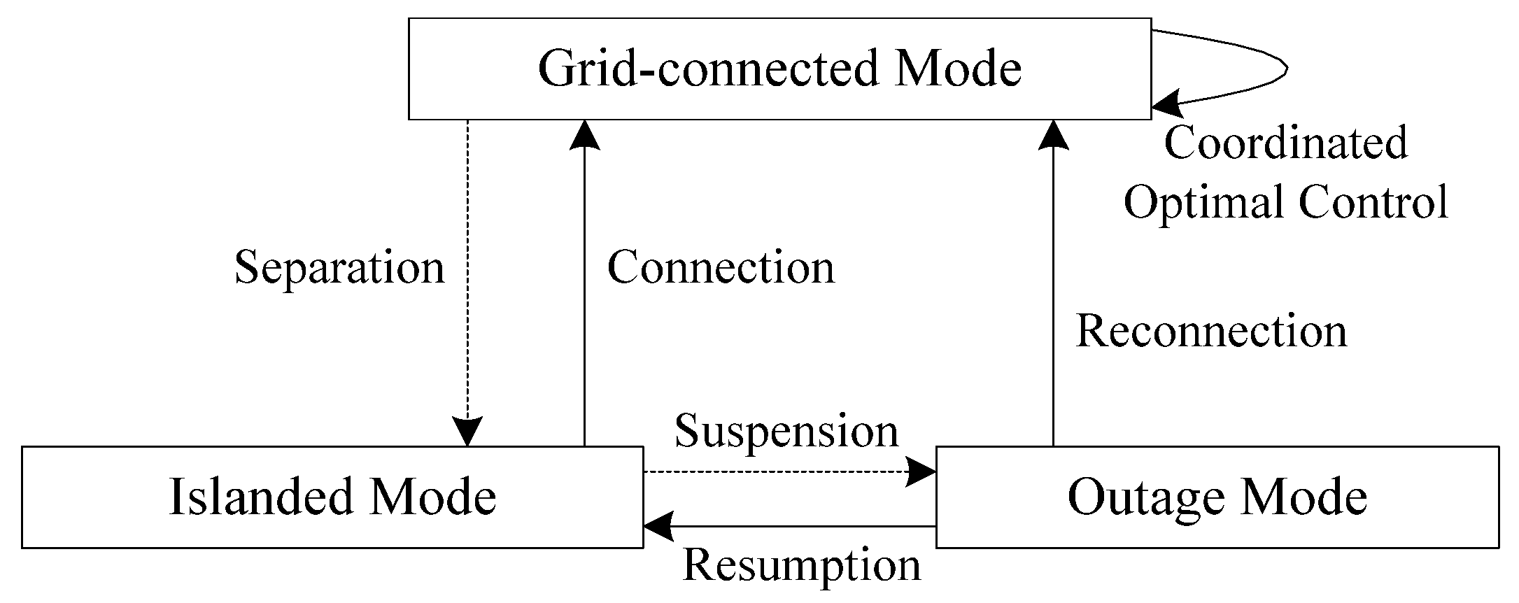
2.1. Operation Modes of Micro-Grids

There are three operation modes for the micro-grid, namely, grid-connected, islanded, and outage modes. A finite state machine representation of the different operational states and their transition conditions is shown in Figure 2.
Figure 2. Finite state machine of micro-grid operation modes.
Energies 08 12396 g002
In grid-connected mode, a micro-grid can transport electrical energy to an external main power grid or absorb energy from the main power grid to maintain the local power supply. The fluctuation of the frequency and the power in the micro-grid system is borne by the main grid, and the voltage and frequency of the micro-grid should be synchronous with the main grid. Thus, each micro source does not need to participate in the regulation of voltage and frequency, which is supported by main grid. The micro power inverter can thus be controlled by the PQ method to output power according to the given reference or maximum output [25,26], and the energy storage device is usually controlled under charging mode.
In islanded mode, in order to maintain the voltage and frequency and to balance the internal power of the micro-grid, one or more master controllable power sources are needed and should be controlled by a constant voltage and constant frequency (CVCF) method or V/f control strategy. The CVCF method has some limitations surrounding the need for a large capacity controllable power source [27,28]. The V/f control strategy is widely used, with which the frequency can be adjusted by active power and the voltage can be regulated by reactive power [29,30]. The remainder of the DGs can still be controlled by a PQ strategy to output active and reactive according to the given reference.
Assuming that the micro-grid is initially operating in grid-connected mode, when or if a transient fault occurs in the main power grid, it should be separated rapidly from the main grid to remain in autonomous operation mode and meet the corresponding local load requirement. The normal voltage and frequency must be supplied by the master DGs in the micro-grid in order to meet the critical load requirement. At the same time, some non-critical power load can be shed if necessary. When the main grid is restored, the micro-grid can be reconnected to the main power grid. However if a power quality event, malfunction or power gap occurs, then the micro-grid will be switched to outage mode.
There are many different kinds of DGs in the micro-grid, including, in the main, PV, wind turbine, storage battery [31]. Some DG sources with intermittent features such as wind turbine, PV, the output performance of which is easily affected by environment factors [32,33], are usually controlled by a PQ method to output power according to the given reference or maximum output; while some other DGs such as energy storage battery, which are easily controlled [34], can be controlled by PQ or V/f methods [35]. The control action is mainly applied via the power interface inverter of each DG. The actual problem yet to be solved is how to preserve the safe, stable and highly-efficient operation of micro-grids under differing operational modes, particularly at the moment of mode transfer.

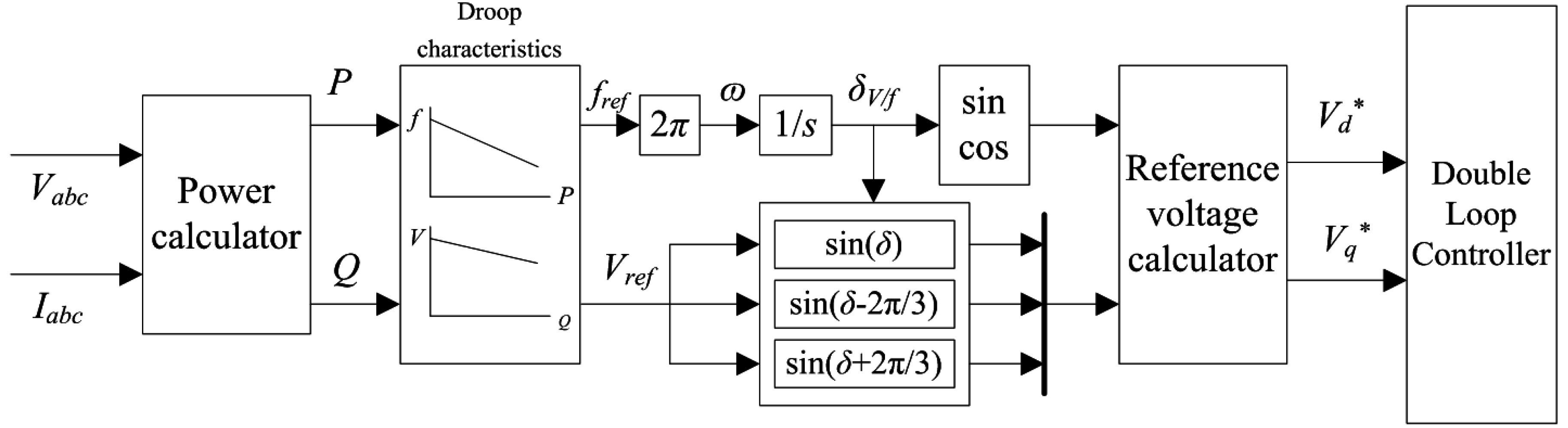
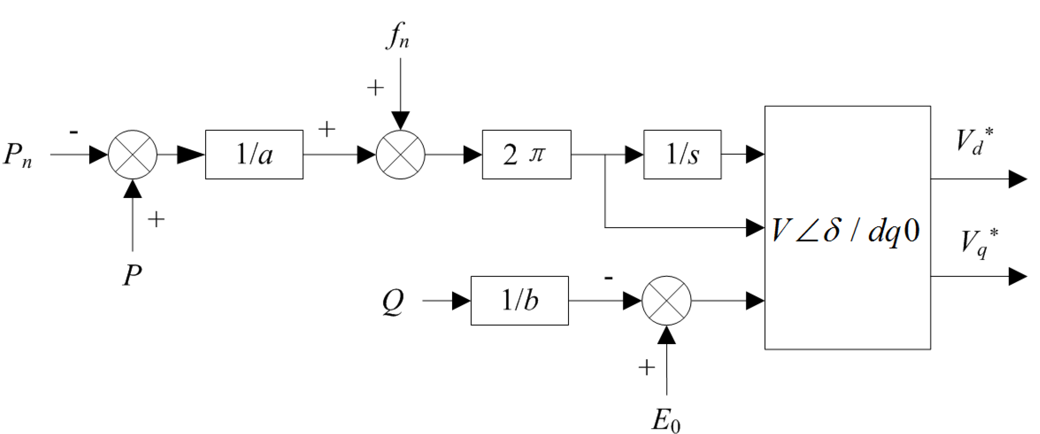
2.2. Droop Based V/f Control Method

The V/f control method resembles the droop characteristics of the regulation of traditional grids to realize varied frequency sharing between different DGs. The support of voltage and frequency in a micro-grid can be achieved at the same time by utilization of V/f control. V/f control method has enabled changes of DG’s self-sensing frequency and voltage and strengthened reliability of micro-grids. The schematic diagram of a V/f controller is shown in Figure 3 [25].
Figure 3. Droop based V/f control.
Energies 08 12396 g003
Here, Pn and fn are rated active output power and the corresponding frequency respectively, a and b are the droop coefficient of active and reactive power, E0 is the output voltage in the case where the output reactive power is zero, V∠δ/dq0 is the coordinate transformation from a three-phase coordinate system to the rotating coordinate system, and Vd* and Vq* represent the output voltage in the d and q axis coordinates respectively, which are thereafter used as the reference for the double loop controller. The droop coefficient can be acquired as follows:
a = P max P n f n f min
b = Q max E 0 E min

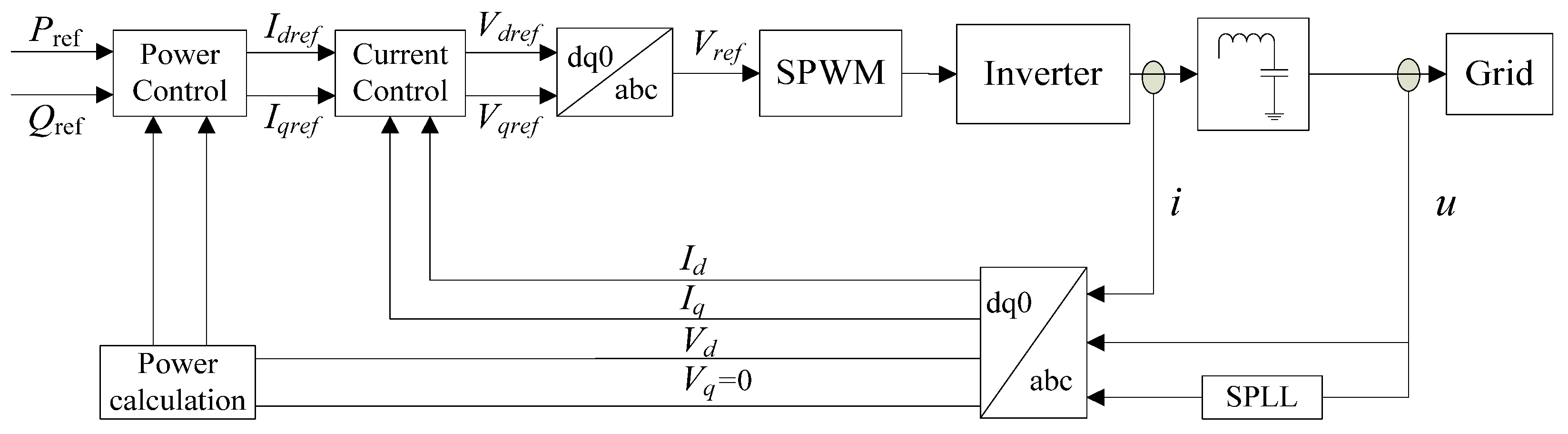
2.3. PQ Control Method

The relationship between the three phase fundamental voltage u and the corresponding voltage magnitude Vm output by the inverter when grid-connecting is as follows:
[ V a V b V c ] = [ V m cos ( ω t ) V m cos ( ω t 2 π 3 ) V m cos ( ω t + 2 π 3 ) ]
Using the method of transformation from a three-phase coordinate system to the dq rotating coordinate system, the Equation (3) can be described as:
[ V d V q ] = T a b c d q [ V a V b V c ] = [ V m 0 ]
Assuming that Id and Iq are the current components in the d and q axis coordinates of output current i of the inverter, the active and reactive power can be described as follows:
{ P = V d I d + V q I q Q = V q I d V d I q
Considering the given reference active power Pref and reactive power Qref, and combining Equations (4) and (5), the reference current for the power inverter can be obtained thus:
{ I d r e f = P r e f V d I q r e f = Q r e f V d
Since Vd is constant, the output active and reactive power of the inverter can be regulated by controlling the current components in the d and q axis coordinates, where the active power P depends on the active current component Id and the reactive power Q depends on the reactive current component Iq. The schematic diagram of PQ control is shown in Figure 4.
Figure 4. The schematic diagram of PQ control.
Energies 08 12396 g004
In Figure 4, as the reference voltage in d and q axis coordinates for the power inverter, Vdref and Vqref are the output of the current controller module, and Vref is the synthetic value of the reference voltage from Vdref and Vqref.

3. Analysis of Transient Oscillations: Case Study

Different degrees of transient oscillations can be seen to occur at the moment of mode transfer in our case study when using the above control methods, indicating that, by setting certain parameters, transient oscillations may be examined in both grid-connecting and islanding processes. Section 3.1 describes the transient oscillations when the micro-grid switches from islanded mode to that of grid-connected mode while Section 3.2 considers the islanding process.

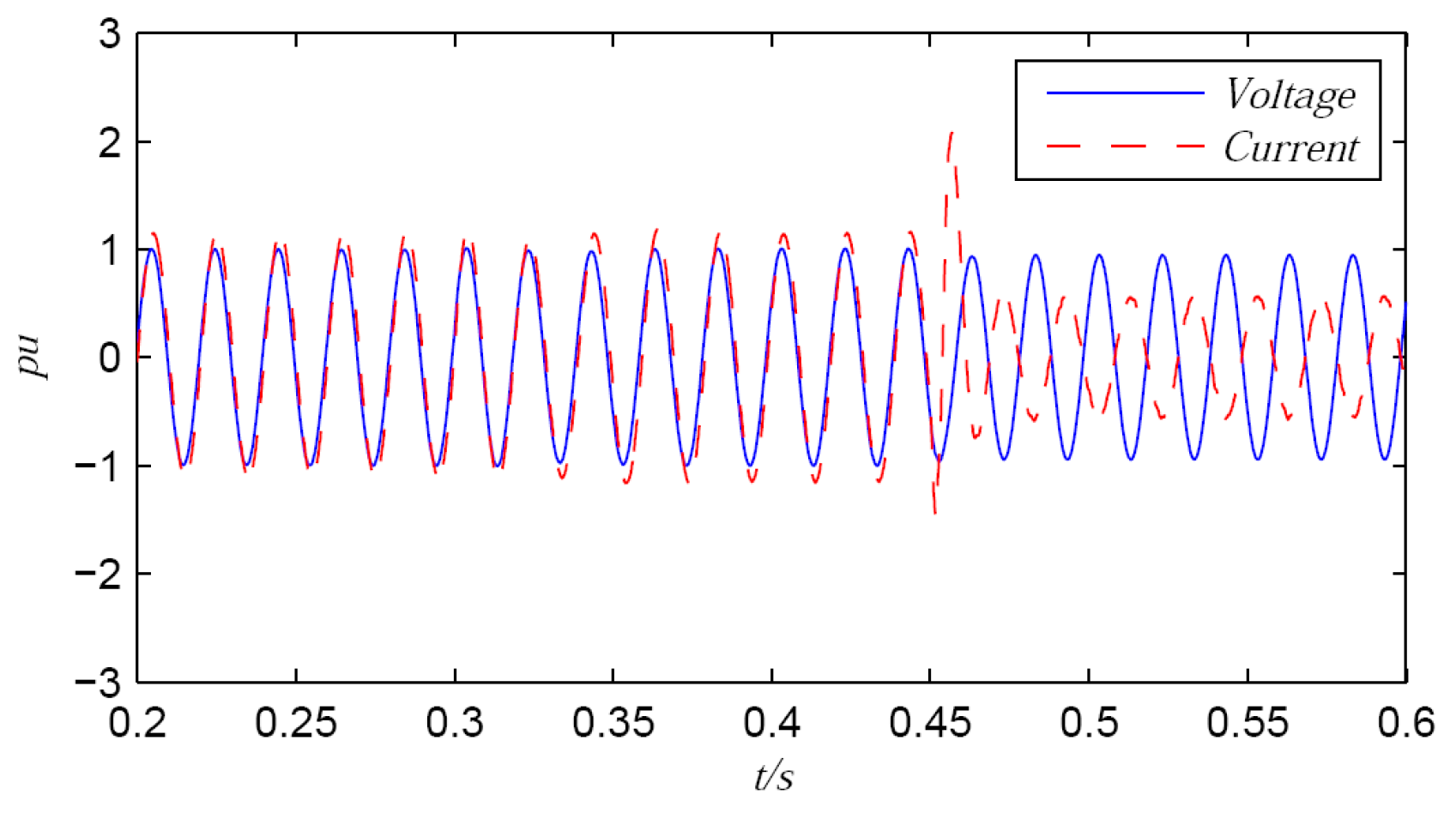
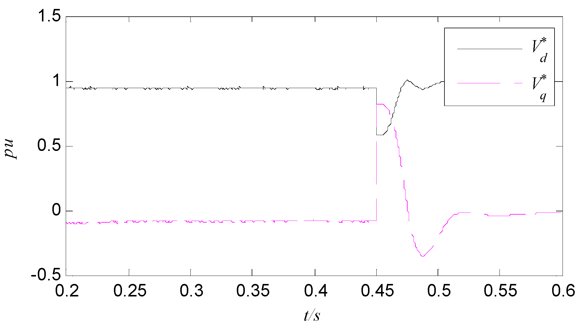
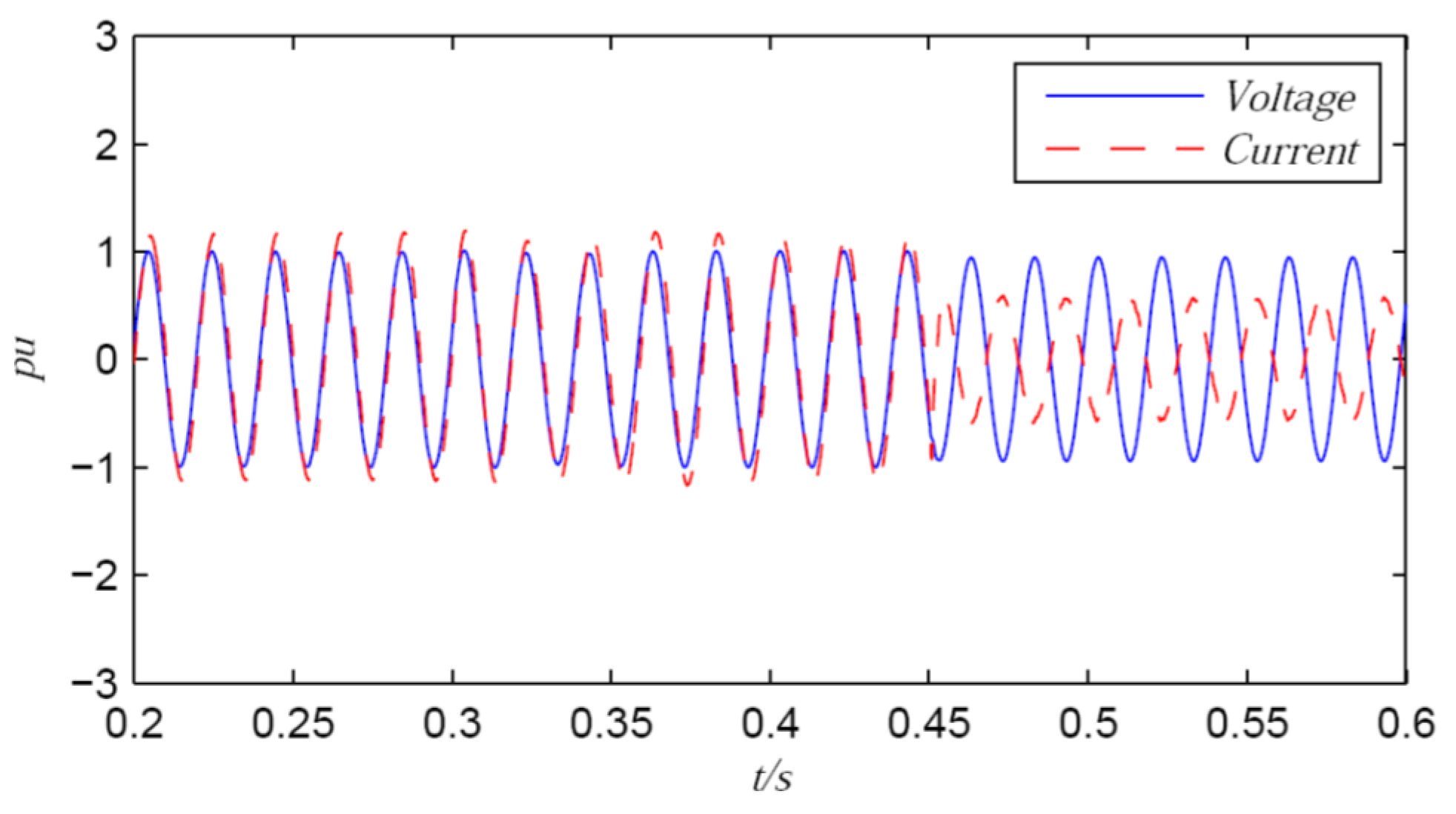
3.1. Transient Oscillations in a Grid-Connecting Process

The micro-grid structure as shown in Figure 1 is used in this case study. The parameters are configured as follows: the voltage in the micro-grid is 380 V, the active and reactive power of load 1 connected to the main power grid are 100 kW and 10 kvar, respectively, the active and reactive power of load 2 are 10 kW and 1 kvar, respectively, the active and reactive power of adjustable load 3 are 2.5 kW and 1 kvar, respectively, the full battery capacity is 200 Ah, the PV and wind turbine are controlled at maximum power output, where the rated power factors are all 1.0; the maximum output power of the PV is 1.6 kW under the standard environment that the light intensity is 1 kW/m2 and the temperature is 25 °C, the maximum output power of wind turbine is 2.3 kW with the condition that the wind speed is 8 m/s and the pitch angle is 0; resistance of the low voltage line is R = 0.5 Ω/km, the filter inductance is L = 0.6 mH and the filter capacitor is C = 1.5 kuF.
This micro-grid is initially considered to operate in the islanded mode and the storage battery, as the main power source, is controlled by the V/f control method. The grid-connecting command is received by the micro-grid at 0.3 s, and the grid-connecting process is finished at 0.45 s; at the same time, the control method for the storage battery is changed from V/f to PQ strategy.
The single phase voltage and current outputs in the grid-connecting process are shown in Figure 5. It can be seen that there is considerable transient oscillation during grid connection. To further analyze the reason for this kind of transient oscillation, the corresponding controller output during the grid-connecting process is provided as shown in Figure 6.
It can be seen that there are great output voltage saltations both in d and q axis coordinates. This is because the V/f control method is switched to PQ strategy when the micro-grid switches from islanded mode to grid-connected mode, while the outputs of the two controllers are different. It is this output voltage peak that mainly contributes to the transient oscillation of the micro-grid at the moment of mode transfer.
Figure 5. Single-phase voltage and current output.
Energies 08 12396 g005
Figure 6. The controller output during the grid-connecting process.
Energies 08 12396 g006

3.2. Transient Oscillations in a Islanding Process

The micro-grid should be cut off in a timely manner from the main gird when some faults or unintentional switching events occur in the main power grid in order to maintain the local power supply. To continue with the case study above, this micro-grid is initially considered to operate in grid-connected mode, and the storage battery, as the main power source, is controlled by PQ control method. The micro-grid is set to be separated at 0.45 s and the control strategy is switched from PQ to V/f for the main power source. The single phase voltage and current outputs in the islanding process is shown in Figure 7.
Figure 7. Single-phase voltage and current output.
Energies 08 12396 g007
It can be seen that the occurrence of transient oscillation is more acute when the micro-grid switches from grid-connected mode to islanding mode. To further analyze the reason for this kind of transient oscillation, in a similar manner, the corresponding controller output during the islanding process is considered as shown in Figure 8.
It can be seen that there are also great output voltage saltations both in d and q axis coordinates, which lead directly to the transient oscillation of the islanding process. This is due to the fact that the d axis component of the offline operating V/f controller is based on the voltage vector of the main grid when grid-connecting, while the d axis component of the online operating V/f controller is based on the voltage vector of the micro-grid when grid-islanding. As a consequence, when the micro-grid is separated from the main grid and the controller is switched from PQ to V/f strategy, it is the asynchrony of the dq rotating coordinate system for V/f controller which causes the significant voltage saltations to occur.
Figure 8. The controller output during islanding process.
Energies 08 12396 g008

4. Modified Control Strategy for Seamless Mode Transfer

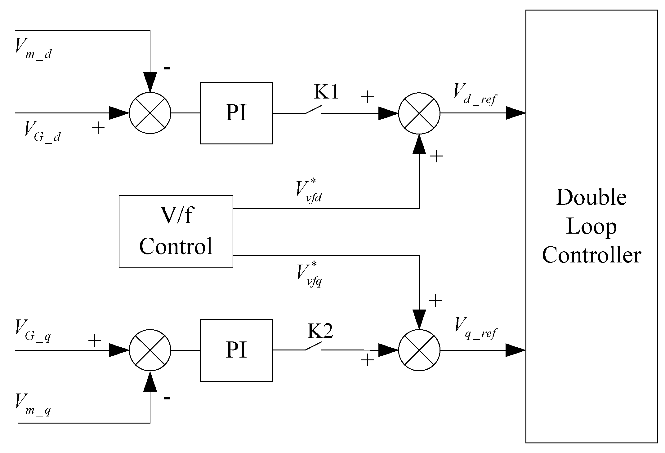
4.1. Improved Pre-Synchronous Controller

To reduce the current surge at PCC, the voltage amplitude, phase angle and the frequency of the micro-grid and the main grid should be pre-synchronized before the micro-grid switches from islanding mode to grid-connected mode. The droop based pre-synchronous control is one of the most widely used strategies that help to finish the grid-connecting pre-synchronized process [36]. It is worth mentioning that traditional droop based pre-synchronous controllers are designed to adjust the voltage difference and frequency difference directly. Considering that droop based control is deviating regulation and the measurement error is ineluctable, it is difficult to acquire voltage and frequency synchronous completely. On the other hand, V/f control, whose purpose is to insure the constant of both DG output voltage amplitude and frequency, is similar to secondary voltage and frequency regulation of power system, which causes interference with the pre-synchronous method, which, in turn, may lead to further transient oscillation. Some simulation results show that the voltage and frequency of inverter power source based on the droop control changes suddenly and the change rate is large [36].
To cope with this problem, the three phase AC voltages are transformed to the DC voltages in the dq rotating coordinate system, which avoids the need for direct regulation for voltage and frequency. Thus, the DC voltages can be regulated by a linear PI (Proportional Integral) controller. The improved pre-synchronous controller in this paper is shown in Figure 9, where, Vm_d, Vm_q and VG_d, VG_q are the d and q components of the bus voltages in the micro-grid side and main grid side respectively; Vd_ref and Vq_ref represent the reference d and q components for the double loop controller.
Figure 9. Structure of Improved Pre-Synchronous Controller.
Energies 08 12396 g009
The synthesized voltage components Vd_ref and Vq_ref, which are superimposed by the corresponding output voltage components of PI and V/f controllers, are taken as the input signals for the double loop controller. The pre-synchronous controller and the V/f controller are working together to maintain the voltage and frequency within the micro-grid. After the grid-connecting process is completed, the pre-synchronous controller will be cut off by switches K1 and K2.

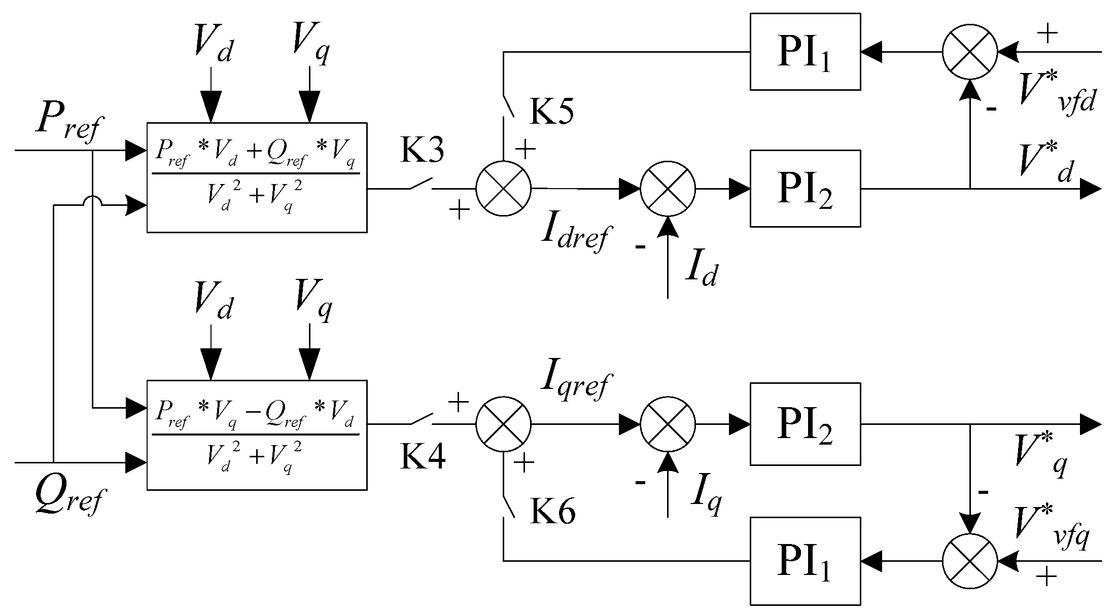
4.2. Status Tracking Based PQ Control Method

As mentioned above, different control strategies should be adopted according to the differing operating modes associated with the micro-grid. To avoid the conflict between the frequencies of the micro-grid and the main grid during grid-connection process, the V/f control method should be switched to the PQ control strategy. However, the mismatch between the outputs of the two controllers can lead to the saltation of the final output signal due to the different control structure. To cope with this problem, a status tracking based PQ control strategy is proposed here. More specifically, to suppress the abrupt change of output voltage when the V/f control is switched to PQ control, the initial output situation of the PQ controller is designed in advance based upon the synchronous tracking of the output situation of the V/f controller.
The relationship between power and current in a dq rotating coordinate system is as follows:
P = V d × I d + V q × I q
Q = V q × I d V d × I q
where, Vd, Vq and Id, Iq are the voltage and current in the d and q axis coordinates respectively.
With Pref, Qref instead of P, Q, and Idref, Iqref instead of Id, Iq in above equations, we then get:
I d r e f = ( P r e f × V d + Q r e f × V q ) / ( V d 2 + V q 2 )
I q r e f = ( P r e f × V q Q r e f × V d ) / ( V d 2 + V q 2 )
where, Pref and Qref are the active and reactive power references respectively for the PQ controller, and Idref and Iqref are the current references respectively in the d and q axis coordinates.
The control method which achieves synchronization of controller output states is shown in Figure 10.
Figure 10. Diagram of the PQ controller based on status tracking.
Energies 08 12396 g010
Vvfd* and Vvfq* are the output voltage components of V/f controller in the dq coordinate system when the micro-grid is operating in the state of islanding. Immediately prior to connecting to the grid, the switches K3 and K4 open, and K5 and K6 closed. The V/f controller is the only contributing controller; meanwhile, the output voltage components of the V/f controller in the dq axis coordinate are used as the reference for the corresponding output voltage components of the PQ controller. Thus the PQ controller can synchronously track the output situation of the V/f controller before mode transfer. At the moment of grid-connection, the online V/f controller is switched to the PQ controller. At the same time, K3 and K4 close while K5 and K6 still remain closed. On the one hand, the output of the PQ strategy is begun to be controlled according to the given reference power; on the other hand, the output voltage components Vvfd* and Vvfq* of the V/f controller, as the auxiliary reference signals, are still contributing to the output of PQ controller. Moreover, the amplitudes, frequencies and phase positions of voltages on both sides of the PCC are synchronized in advance by the pre-synchronous controller. Thus, the control output has no abrupt change but one that is rather gentle in the grid-connecting process. When a grid connection is being established, K5 and K6 open while K3 and K4 still keep closed, the PQ controller is the only contributing controller, which is totally controlled according to the given reference power.
Based on this modified control strategy, with the same system parameters configured as described in Section 3.1 and the parameters kp = 0.4 and ki = 80 configured for PI controllers, the single phase voltage and current outputs in the grid-connecting process and the corresponding control output during the grid-connecting process are provided as shown in Figure 11 and Figure 12.
Using the results deriving from the traditional control method (shown in Figure 5 and Figure 6) as a ground truth, the transient oscillation of the micro-grid can be seen to be effectively suppressed together with the attainment of smooth switching when grid-connecting.
Figure 11. Single-phase voltage and current output by refined controller.
Energies 08 12396 g011
Figure 12. The controller output during micro-grid switches to grid-connected mode.
Energies 08 12396 g012

4.3. dq Rotating Coordinate Synchronization Based V/f Control Method

To suppress the transient oscillation, the controller output should not be changed acutely when the micro-grid switches from grid-connected mode to islanded mode. Unfortunately, at the moment of grid-islanding, the transition from a grid-frequency-following control at certain output power to self-generated-frequency control at different output power leads to a power angle disturbance that affects the relative stability of the power sharing dynamics. The bus voltage is dominated by the main power grid during connected mode and switches to its subsystems when it comes to islanding mode; this grid-islanding action is a kind of system reboot of the micro-grid [12]. Accordingly, the dq rotating coordinate system for V/f controller is always unsynchronized with respect to the power angle under different modes. As analyzed in Section 3.2, the dq axis component of the offline operating V/f controller is based on voltage vector of the main grid when grid-connecting, while that of the online operating V/f controller is based on voltage vector of the micro-grid when grid-islanding. As a result of these features, the output voltage of the V/f controller may change acutely when the V/f controller is returned back online with the mode transfer.
To avoid the abrupt change of the V/f controller itself at the moment of grid-islanding, the datum reference of the V/f controller in the dq axis coordinate should be kept consistent. In order to maintain the consistency of the datum references for the dq axis coordinate, the output component calculation of the V/f controller in the dq axis coordinate is based on the synthetic voltage vector according to the droop characteristic. In other words, the reference voltage vector is synchronous with the dq rotating coordinate. The dq rotating coordinate synchronization based control method is shown in Figure 13.
Figure 13. Diagram of the V/f controller based on dq rotating coordinate synchronization.
Energies 08 12396 g013
Based on this modified control strategy with the same system parameters configured as described in Section 3.2, the simulation results based on the above control method are shown in Figure 14 and Figure 15.
When one compares these results with those depicted in Figure 7 and Figure 8, we can see that the disturbance of the output signals are greatly decreased and that the transient oscillation of the micro-grid is effectively suppressed and the smooth switching is obtained when the micro-grid is detaching itself from the main grid.
Figure 14. Single-phase voltage and current output by synchronization of dq rotating coordinate.
Energies 08 12396 g014
Figure 15. The output of controller during the operation mode switching to isolated mode.
Energies 08 12396 g015
In order to further verify the effectiveness of the proposed control strategies, additional experiments are necessary and considered in our case study in the following Section 5.

5. Experiments and Analysis

The experiments that follow seek to create a number of conditions under which the micro-grid may operate. As such these experiments simulate changing environmental conditions—sunlight (light intensity) and wind speed, and furthermore, investigate algorithm performance in load switching and mode switching. The micro-grid structure shown in Figure 1 together with the associated control architecture will now be utilized as the vehicle for our case study, replicating the system parameters described in Section 3.1.

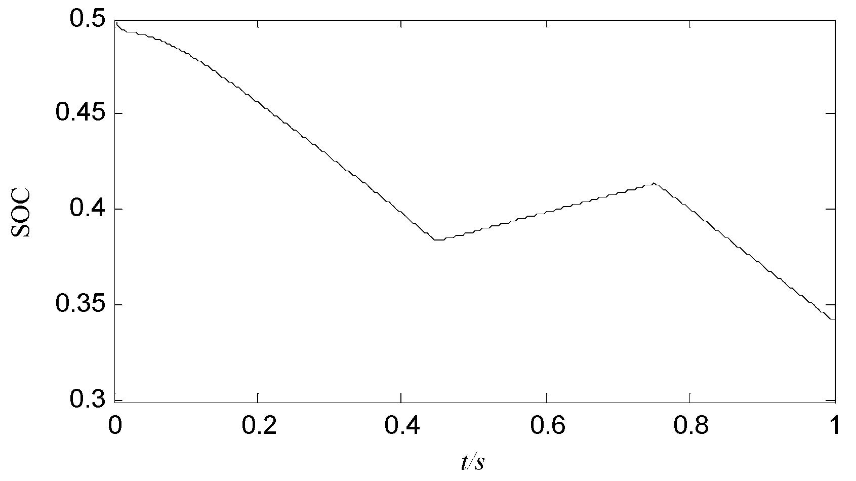
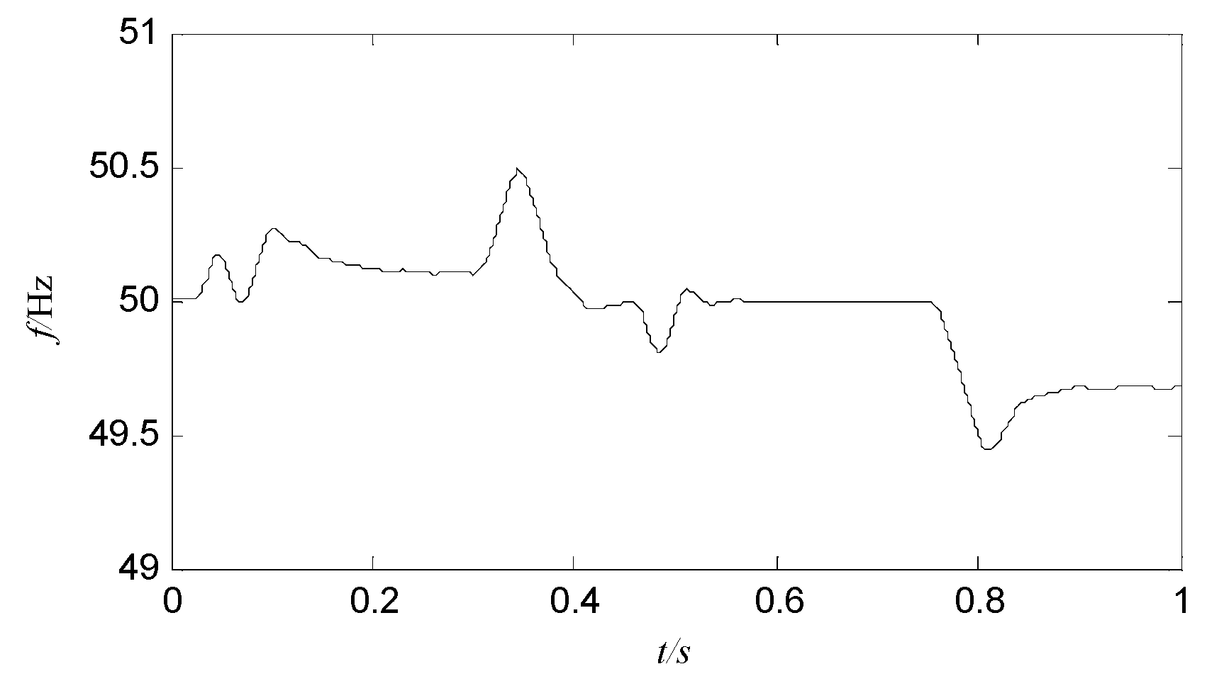
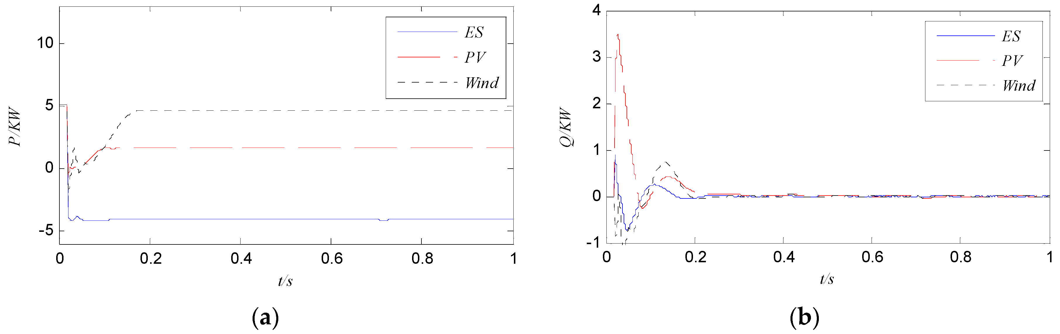
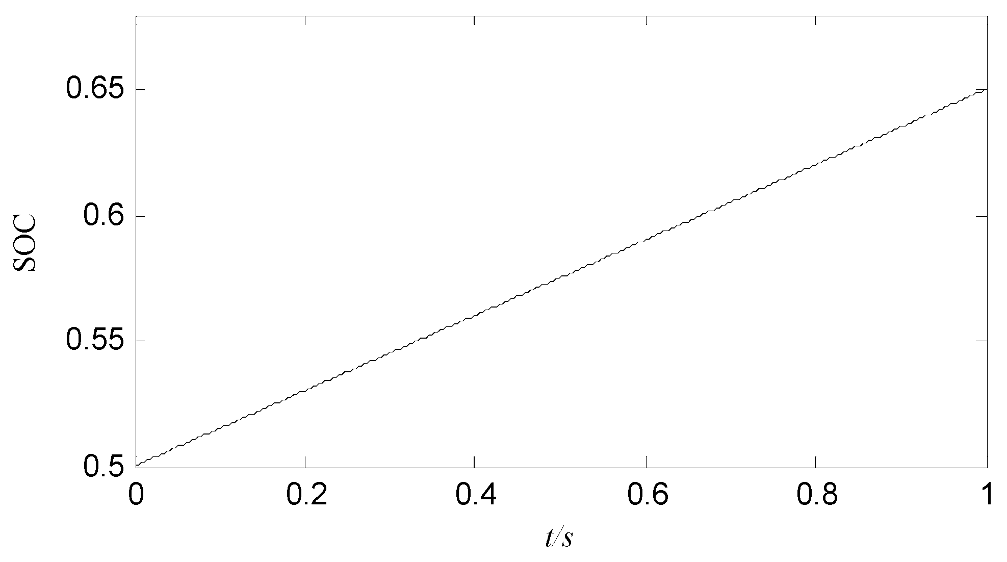
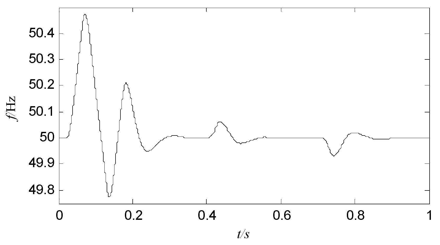
5.1. Light Intensity and Wind Speed Changing in Islanded Mode

In the islanded mode, it is the V/f controlled master power sources and the PQ controlled DGs that balance the internal power of the micro-grid. The total power output within the micro-grid must be maintained and kept consistent by the control system according to changes in the related environment, especially changes of light intensity and wind speed. A large part of complaints on "bad power quality" are in fact the rapid voltage changes due to sudden light intensity and wind speed changes. To illustrate the effectiveness of our control strategy, light intensity and wind speed changes are fundamental to the case study.
System parameters, as described in Section 3.1, are replicated here; moreover, an additional set of experimental parameters are configured as follows: the light density is 1200 W/m2 during 0–0.3 s, 600 W/m2 during 0.3–0.6 s, and again 1200 W/m2 during 0.6–1.5 s; the wind speed is 8 m/s during 0–0.9 s, 10 m/s during 0.9–1.2 s, and again 8 m/s after 1.2 s. The sensitive power load 3 is online. The simulation results are shown in Figure 16 and Figure 17.
Figure 16. Active and reactive power output curves of micro-source. (a) Active power output; (b) Reactive power output.
Energies 08 12396 g016
Figure 17. The frequency response of micro-grid.
Energies 08 12396 g017
It can be seen that, with the light density decreasing, the active power output of the PV is decreasing while that of the storage battery is increasing, and vice versa; with the wind speed increasing, the active power output of the wind turbine is increasing while that of the storage battery is decreasing, and vice versa. The PV and wind turbine can be controlled in accordance with the maximum power output. Results confirm that, in the case of islanded mode, the power output of each micro source can be adjusted rapidly and the total power output within the micro-grid can be maintained and kept consistent by the control system according to changes of the related environment. In contrast and as expected, it can be seen from Figure 17 that the frequency of the micro-grid exhibits only minor variations relative to changes of either light intensity or wind speed.

5.2. Load Switching in Grid-Connected Mode

In the grid-connected mode, the power output of the PQ controlled DGs should not be affected by the local power loads changing since the fluctuation of power in the micro-grid is borne by the main grid. So, load switching in grid-connected mode is tested in our case study.
Parameters in this experiment are configured as follows: the light density is 1000 W/m2, the wind speed is 8 m/s, and the battery is charging with a constant current. The sensitive power load 3 is switched in during 0.4–0.7 s and switched out after 0.7 s. The power output curves of micro-sources are shown in Figure 18.
It can be seen that the storage battery is equivalent to a power load when charging with constant current, and that the PV and wind turbine are controlled in accordance with the maximum power output. The power in the micro-grid is balanced by the main power grid, so the output power of each micro source does not change with load switching. The curve of battery state of charge (SOC) and frequency response of the micro-grid are shown in Figure 19 and Figure 20 respectively.
It can be seen that the battery is absorbing power from the main grid and the electric quantity is increasing, the frequency changed slightly but within the change indicator and can be returned rapidly to the stable state.
Figure 18. Active and reactive power output curves of micro-source. (a) Active power output; (b) Reactive power output.
Energies 08 12396 g018
Figure 19. The curve of battery state of charge (SOC).
Energies 08 12396 g019
Figure 20. The frequency response of the micro-grid.
Energies 08 12396 g020

5.3. Grid-Connected/Islanding Smooth Switching

Moreover, while the mode transfers from islanded mode to grid-connected mode, and grid-connected mode to islanded mode, were tested separately in Section 4, the successive transfers between grid-connected and islanded operation modes are further considered in this case study to test the developed control strategy.
In this experiment, parameters are configured as follows: the micro-grid is operating in islanding mode during 0–0.45 s, where droop based V/f control is used for battery’s discharge mode during 0–0.3 s and pre-synchronous controller is activated to follow the voltage of the main grid. The micro-grid is connected to the main grid at 0.45 s and the battery is switched to charge mode with a constant current; then the micro-grid is separated from main grid at 0.75 s and the battery is switched to discharge mode with droop based V/f control. The PV and wind turbine are controlled throughout in accordance with the maximum power output. The voltage and current and power output are shown in Figure 21 and Figure 22 respectively.
Figure 21. Single-phase voltage and current curves of micro-source. (a) Voltage and current output of storage battery; (b) Voltage and current output of PV; (c) Voltage and current output of wind turbine.
Energies 08 12396 g021
Figure 22. Active and reactive power output curves of micro-source. (a) Active power output; (b) Reactive power output.
Energies 08 12396 g022
It can be seen that the voltage and current of each micro source are all seamlessly transmitted notwithstanding the fact that the control strategy is changed from V/f to PQ when grid-connecting at 0.45 s; smooth switching control is also obtained when the micro-grid is separating from the main grid at 0.75. Compared with the results deriving from the traditional control method (shown in Figure 5 and Figure 6), these results confirmed the efficacy of the modified control strategy for voltage and current adjustment when grid-connected or islanding switching of the micro-grid.
As can be seen from Figure 22, the active power output of the storage battery decreases only marginally after the pre-synchronous controller is put into operation, and the fluctuations of active and reactive power output are negligible during either the grid-connecting or islanding processes. The power output of the PV and the wind turbine are all in accordance with the maximum power output. The results confirm the efficacy of the modified control strategy for both active and reactive power output adjustment when grid-connected/islanding switching of the micro-grid.
The curve of battery state of charge (SOC) (Figure 23) indicates the change of electric quantity under different operating modes. The frequency response of the micro-grid is shown in Figure 24.
Figure 23. The curves of battery state of charge (SOC).
Energies 08 12396 g023
Figure 24. The frequency response of micro-grid.
Energies 08 12396 g024
The frequency changed slightly in the range of (−0.5, 0.5) but within the change indicator and can be returned rapidly to the stable state.

6. Conclusions

The micro-grid can be operated either in the grid-connected mode or in islanded mode; seamless mode transfer however is an important prerequisite for maintaining safe and stable operation of micro-grids. In order to ameliorate the effect of power quality during mode transfer, this paper establishes the underlyinsssg cause of the transient oscillation associated with mode transfer via a case study focusing on an archetypical micro-grid with the Wind-PV-ES hybrid system. Thereafter, a modified control strategy for seamless mode transfer is formulated. The primary contribution of this paper is an improved PQ control, the provision of a mechanism by which to ensure the continuity of the controller output whereby the output of the PQ controller always synchronously tracks the output of the V/f controller as the micro-grid switches from islanded mode to grid-connected mode. Additionally we propose a dq rotating coordinate synchronization based on a V/f control method when the micro-grid switches from grid-connected mode to islanded mode. The simulation results presented indicate that the modified control method is effective in dominating the micro-grid and suppressing the transient oscillations during the mode transfer.

Acknowledgments

The authors gratefully acknowledge the support of the National Natural Science Foundation of China (61105082), Jiangsu Government Scholarship for Overseas Studies, China (JS-2013-219). “Qing Lan” Project of Jiangsu Province, China (QL2012) and “1311 Talent Plan” of Nanjing University of Posts and Communications (NY2013).

Author Contributions

Tengfei Zhang conceived the core concepts for this research and paper. Dong Yue aided with control strategy and experimental validation. Michael O’Grady and Gregory O’Hare advised academically. All authors collaborated in the preparation, revisions and general editing of this manuscript.

Conflicts of Interest

The authors declare no conflict of interest.

References

  1. Wu, D.; Tang, F.; Dragicevic, T.; Vasquez, J.C.; Guerrero, J.M. A Control Architecture to Coordinate Renewable Energy Sources and Energy Storage Systems in Islanded Microgrids. IEEE Trans. Smart Grid 2015, 6, 1156–1166. [Google Scholar] [CrossRef]
  2. Guerrero, J.M.; Vasquez, J.C.; Matas, J.; de Vicuna, L.G.; Castilla, M. Hierarchical control of droop-controlled AC and DC microgrids-A general approach toward standardization. IEEE Trans. Ind. Electron. 2011, 58, 158–172. [Google Scholar] [CrossRef]
  3. Lu, Z.X.; Wang, C.X.; Min, Y. Overview on microgrid research. Autom. Electron. Power Syst. 2007, 31, 100–107. [Google Scholar]
  4. Liu, Y.H.; Zhang, N.; Zhang, X. Research on grid-connected/islanding smooth switching of micro-grid based on energy storage. In Proceedings of the IEEE International Conference on Power System Technology, Auckland, New Zealand, 30 October–2 November 2012; pp. 1–5.
  5. Zhao, D.M.; Zhang, N.; Liu, Y.H. Micro-grid connected/islanding operation based on wind and PV hybrid power system. In Proceedings of the IEEE Innovative Smart Grid Technologies-Asia (ISGT Asia), Tianjin, China, 21–24 May 2012; pp. 1–6.
  6. Zhang, Z.; Chen, W.; Zhang, Z. A new seamless transfer control strategy of the microgrid. Sci. World J. 2014, 2014, 1–9. [Google Scholar] [CrossRef] [PubMed]
  7. Yang, Z.; Wang, C.; Che, Y. A small-scale microgrid system with flexible modes of operation. Autom. Electron. Power Syst. 2009, 33, 89–92. [Google Scholar]
  8. Huang, W.; Lu, M.; Zhang, L. Survey on microgrid control strategies. Energy Procedia 2011, 12, 206–212. [Google Scholar] [CrossRef]
  9. Adhikari, S.; Li, F. Coordinated Vf and PQ control of solar photovoltaic generators with MPPT and battery storage in microgrids. IEEE Trans. Smart Grid 2014, 5, 1270–1281. [Google Scholar] [CrossRef]
  10. Fang, L.; Chen, J.; Chen, X.; Gong, C.; Fan, Y. Analysis and control of smooth transferring for micro-grid with droop control. In Proceedings of the IEEE Vehicle Power and Propulsion Conference (VPPC), Beijing, China, 15–18 October 2013; pp. 1–5.
  11. Vandoorn, T.L.; Meersman, B.; de Kooning, J.D.; Vandevelde, L. Transition from islanded to grid-connected mode of microgrids with voltage-based droop control. IEEE Trans. Power Syst. 2013, 28, 2545–2553. [Google Scholar] [CrossRef] [Green Version]
  12. Liu, B.; Zhuo, F.; Zhu, Y.; Hao, Y. System operation and energy management of a renewable energy-based DC micro-grid for high penetration depth application. IEEE Trans. Smart Grid 2015, 6, 1147–1155. [Google Scholar] [CrossRef]
  13. Katiraei, F.; Iravani, M.R.; Lehn, P.W. Micro-grid autonomous operation during and subsequent to islanding process. IEEE Trans. Power Deliv. 2005, 20, 248–257. [Google Scholar] [CrossRef]
  14. Meegahapola, L.G.; Robinson, D.; Agalgaonkar, A.P.; Perera, S.; Ciufo, P. Microgrids of commercial buildings: Strategies to manage mode transfer from grid connected to islanded mode. IEEE Trans. Sust. Energy 2014, 5, 1337–1347. [Google Scholar] [CrossRef]
  15. Mohamed, Y.A.R.I.; Radwan, A. Hierarchical control system for robust microgrid operation and seamless mode transfer in active distribution systems. IEEE Trans. Smart Grid 2011, 2, 352–362. [Google Scholar] [CrossRef]
  16. Hwang, T.S.; Park, S.Y. A seamless control strategy of a distributed generation inverter for the critical load safety under strict grid disturbances. IEEE Trans. Power Electron. 2013, 28, 4780–4790. [Google Scholar] [CrossRef]
  17. Ashabani, S.M.; Mohamed, Y.A.R. A flexible control strategy for grid-connected and islanded microgrids with enhanced stability using nonlinear microgrid stabilizer. IEEE Trans. Smart Grid 2012, 3, 1291–1301. [Google Scholar] [CrossRef]
  18. Ashabani, S.M.; Mohamed, Y.A.R. General interface for power management of micro-grids using nonlinear cooperative droop control. IEEE Trans. Power Syst. 2013, 28, 2929–2941. [Google Scholar] [CrossRef]
  19. Ashabani, S.M.; Mohamed, Y.A.R. Integrating VSCs to weak grids by nonlinear power damping controller with self-synchronization capability. IEEE Trans. Power Syst. 2014, 29, 805–814. [Google Scholar] [CrossRef]
  20. Ashabani, M.; Freijedo Fernandez, F.D.; Golestan, S.; Guerrero, J.M. Inducverters: PLL-Less Converters with Auto-Synchronization and Emulated Inertia Capability. Available online: http://vbn.aau.dk/ws/files/217421230/converter_corrections_last_version.pdf (accessed on 3 December 2015).
  21. Jiang, J.; Duan, S.; Chen, Z. Research on control strategy for three-phase double mode inverter. Trans. China Electrotech. Soc. 2012, 27, 52–58. [Google Scholar]
  22. Yang, Z.L.; Wu, C.S.; Wang, H. Design of three-phase inverter system with double mode of grid-connection and stand-alone. Power Electron. 2010, 44, 14–16. [Google Scholar]
  23. Integration of Distributed Energy Resources: The CERTS Microgrid Concept. Available online: http://www.google.com.hk/url?sa=t&rct=j&q=&esrc=s&source=web&cd=1&ved=0ahUKEwj3wviswb7JAhXIpJQKHaiBAqcQFggfMAA&url=http%3A%2F%2Fbnrg.eecs.berkeley.edu%2F~randy%2FCourses%2FCS294.F09%2FMicroGrid.pdf&usg=AFQjCNHMSY1rAeFXm1z9Mrh6EGUjyyVDhg&cad=rja (accessed on 3 December 2015).
  24. Huang, P.H.; Liu, P.C.; Xiao, W.; Moursi, E.; Shawky, M. A novel droop-based average voltage sharing control strategy for DC microgrids. IEEE Trans. Smart Grid 2015, 6, 1096–1106. [Google Scholar] [CrossRef]
  25. Pan, Y.; Li, P.Q.; Li, X.R.; Lei, B. Strategy of research and application for the microgrid coordinated control. In Proceedings of the IEEE Advanced Power System Automation and Protection (APAP), Beijing, China, 16–20 October 2011; pp. 873–878.
  26. Gao, D.K.; Jiang, J.G.; Zhang, Y.H. Design of microgrid control strategy using voltage amplitude and phase angle droop control. Autom. Electron. Power Syst. 2012, 36, 29–34. [Google Scholar]
  27. Wang, Z.; Zhu, S.; Zhou, S. Controller design for inverter-based distributed generation. Autom. Electron. Power Syst. 2004, 28, 61–66. [Google Scholar]
  28. Huang, W.; Zhang, J.H.; Wu, Z.P.; Niu, M. Dynamic modelling and simulation of a Micro-turbine generation system in the microgrid. In Proceedings of the IEEE Sustainable Energy Technologies (ICSET), Singapore, 24–27 November 2008; pp. 345–350.
  29. Huang, X.; Jin, X.M. A voltage and frequency droop control method for microsources. Trans. China Electrotech. Soc. 2012, 27, 29–36. [Google Scholar]
  30. Kim, J.Y.; Kim, S.K.; Jeon, J.H. Coordinated state-of-charge control strategy for microgrid during islanded operation. In Proceedings of the 3rd IEEE International Symposium on Power Electronics for Distributed Generation systems (PEDG), Aalborg, Denmark, 25–28 June 2012; pp. 133–139.
  31. Zeng, Z.; Zhao, R.; Yang, H.; Tang, S. Policies and demonstrations of micro-grids in China: A review. Renew. Sust. Energy Rev. 2014, 29, 701–718. [Google Scholar] [CrossRef]
  32. Bidram, A.; Davoudi, A. Hierarchical structure of microgrids control system. IEEE Trans. Smart Grid 2012, 3, 1963–1976. [Google Scholar] [CrossRef]
  33. Li, C.H.; Zhu, X.J. Dynamic modeling and simulation of hybrid energy storage-based photovoltaic microgrid. Power Syst. Technol. 2013, 37, 39–46. [Google Scholar]
  34. Wang, C.; Nehrir, M.H.; Gao, H. Control of PEM fuel cell distributed generation systems. IEEE Trans. Energy Convers. 2006, 21, 586–595. [Google Scholar] [CrossRef]
  35. Guerrero, J.M.; Vasquez, J.C.; Matas, J.; Castilla, M.; de Vicuňa, L.G. Control strategy for flexible microgrid based on parallel line-interactive UPS systems. IEEE Trans. Ind. Electron. 2009, 56, 726–736. [Google Scholar] [CrossRef]
  36. Wang, K.; Wang, Z.Z.; Chai, J.Y.; You, R.; Gan, S. Analysis of Grid-connecting Pre-synchronized Process for Synchronously Controlled Inverter Power Source. Autom. Electron. Power Syst. 2015, 39, 152–158. [Google Scholar]

