
Genetic Algorithm-Based Design Optimization of Electromagnetic Valve Actuators in Combustion Engines

Abstract
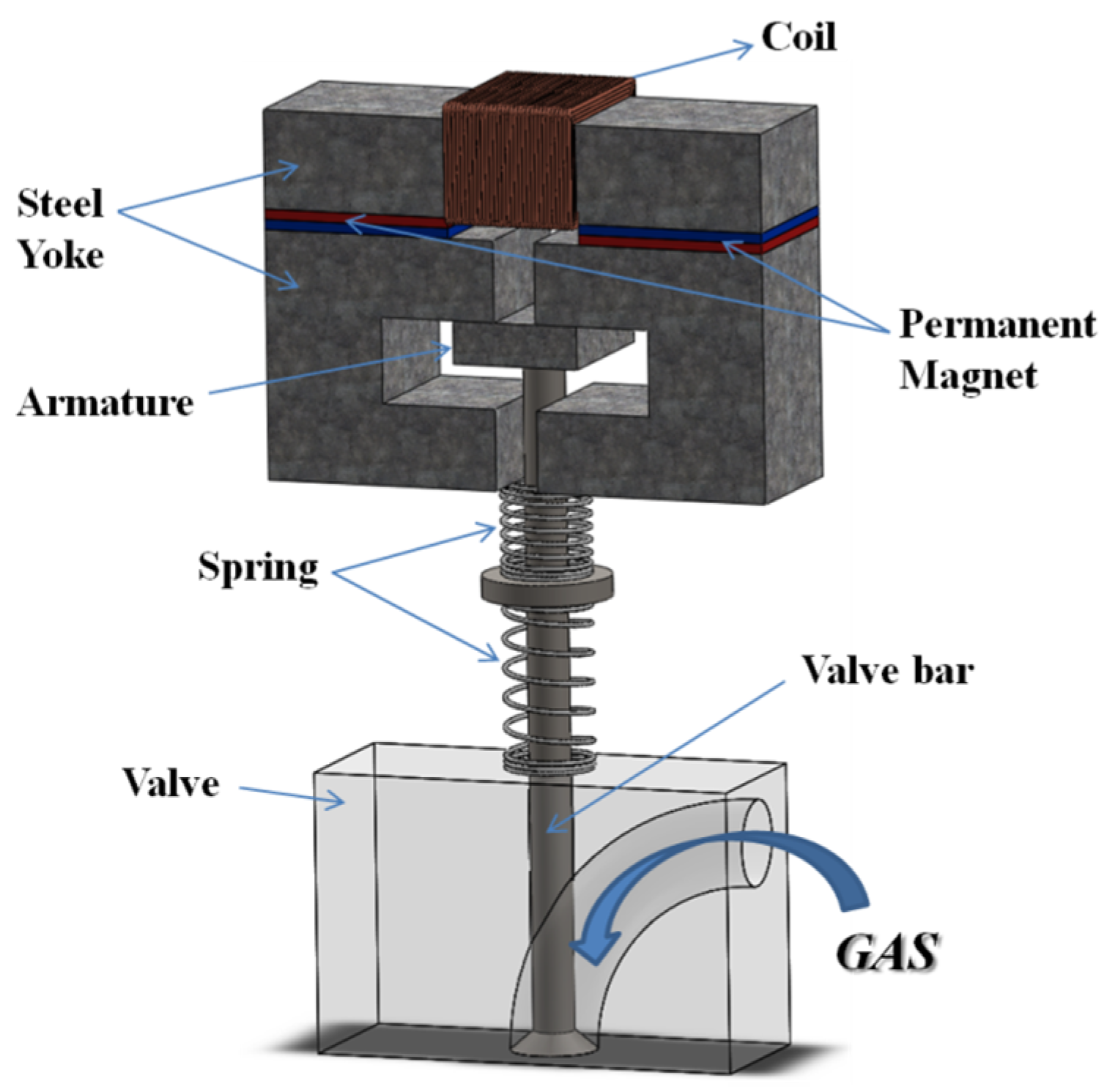
:1. Introduction
2. Design Optimization
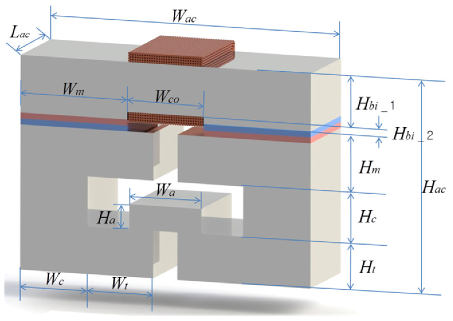
2.1. Optimization Variables and Constraint Conditions
- The thickness and width of the actuator are fixed. The height of the actuator, however, can be extended because extra space in the direction of height is created due to the removal of the camshaft.
- Maximum teeth width (Wt) is set such that the minimum gap between teeth is 10 mm.
- The size of the permanent magnet remains fixed and the same as the one of the existing design. The optimization in this study does not aim to enlarge the magnetic latching force by increasing of the size of the permanent magnets.
- After the dimensions of the core and teeth are determined, the width (Wa) and height (Ha) of the armature are restricted so that the armature can properly fit inside the air band, which allows 8 mm longitudinal air-gap for the required armature motion.
- The shapes of the lower teeth and the upper teeth are designed to be symmetric to the neutral line.

2.2. Objective Function
- k: Available spring stiffness;
- m: Moving mass including armature and engine valve;
- : Frequency of vibration (natural frequency);
- : Magnetic latching force;
- : Distance from neutral to lower end of stroke;
- : Volume of armature;
- : Mass density of steel;
- : Mass of engine valve.
2.3. Optimization Procedures and Results
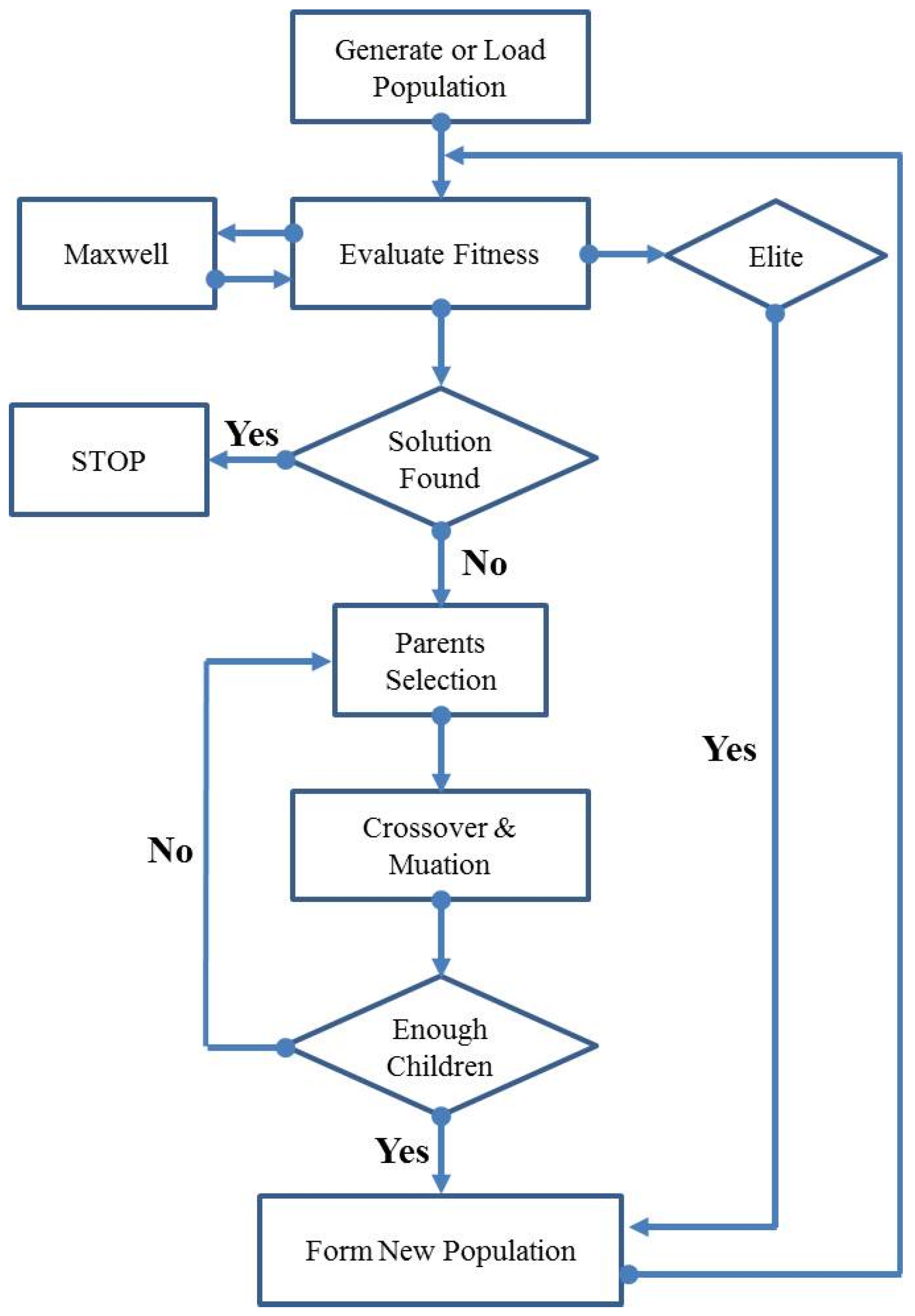
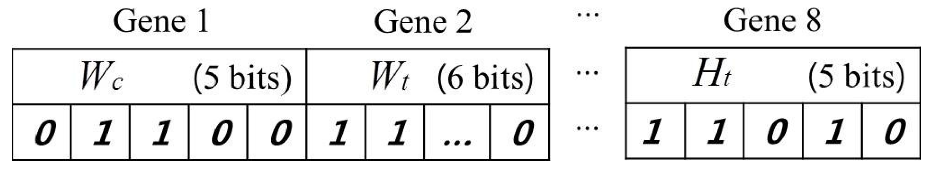
2.3.1. Optimization Procedure and Methods


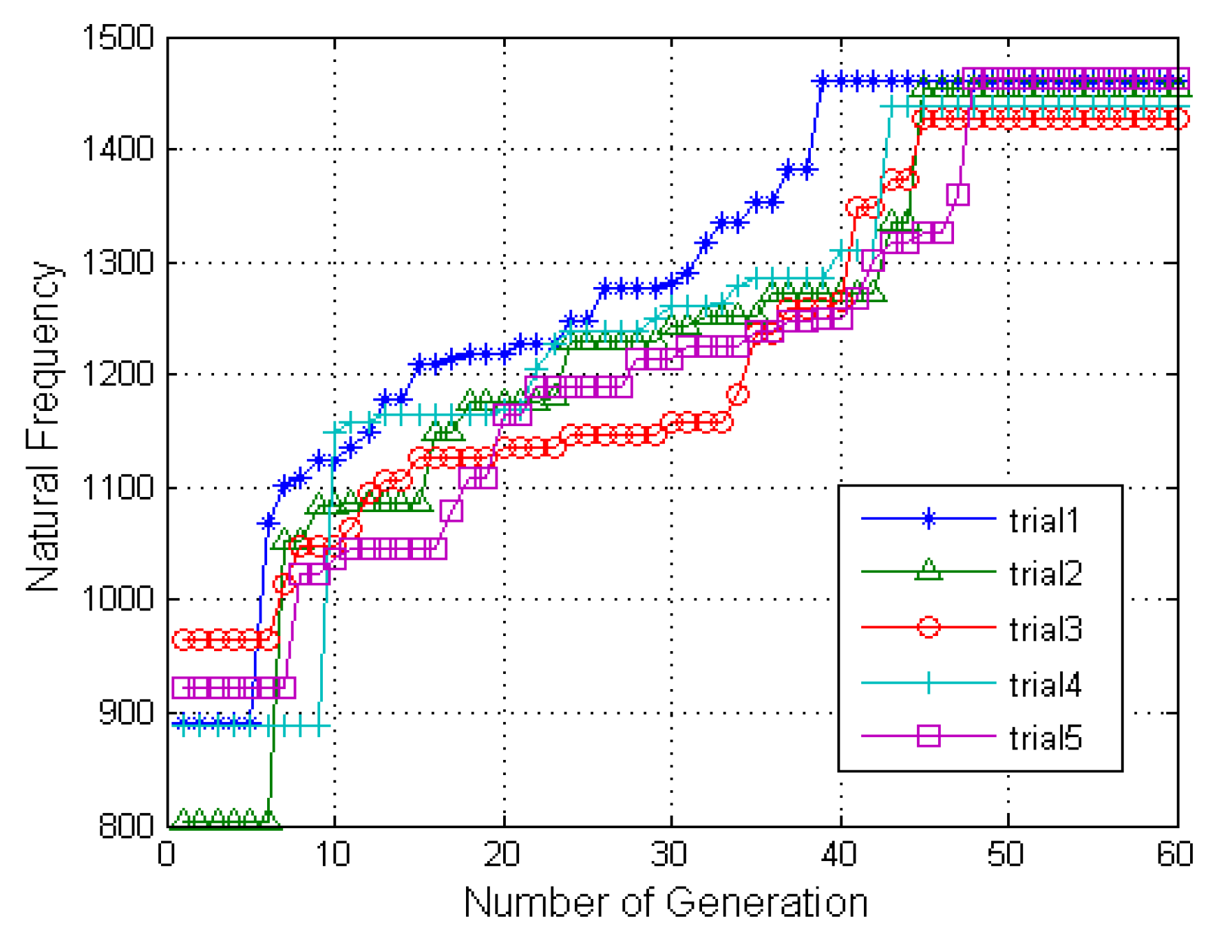
2.3.2. Optimization Results

| Symbol | Quantity | Exiting Dimensions | New Optimized Dimensions |
|---|---|---|---|
| Lac | Thickness of actuator | 38.1 | 38.1 |
| Wac | Width of actuator | 120.65 | 120.65 |
| Hac | Height of actuator | 93.34 | 95 |
| Wco | Width of coil | 31.75 | 31.75 |
| Wm | Width of magnet | 44.45 | 44.45 |
| Hm | Height of magnet | 4.7625 | 4.7625 |
| Wa | Width of armature | 44.45 | 30.216 |
| Ha | Height of armature | 19.03 | 12 |
| Wt | Width of teeth | 34.29 | 27.325 |
| Ht | Height of teeth | 19.05 | 19 |
| Wc | Width of core | 19.05 | 28 |
| Hbi_1 | Height of back iron 1 | 19.05 | 28.75 |
| Hbi_2 | Height of back iron 2 | 4.7625 | 3.5 |
| Characteristics | Existing Design | Optimal Design |
|---|---|---|
| Magnetic latching force (N) | 1525 | 1262 |
| Available Spring stiffness (kN/m) | 358 | 292 |
| Moving mass (kg) | 0.284 | 0.136 |
| Natural frequency | 1123 | 1465 |
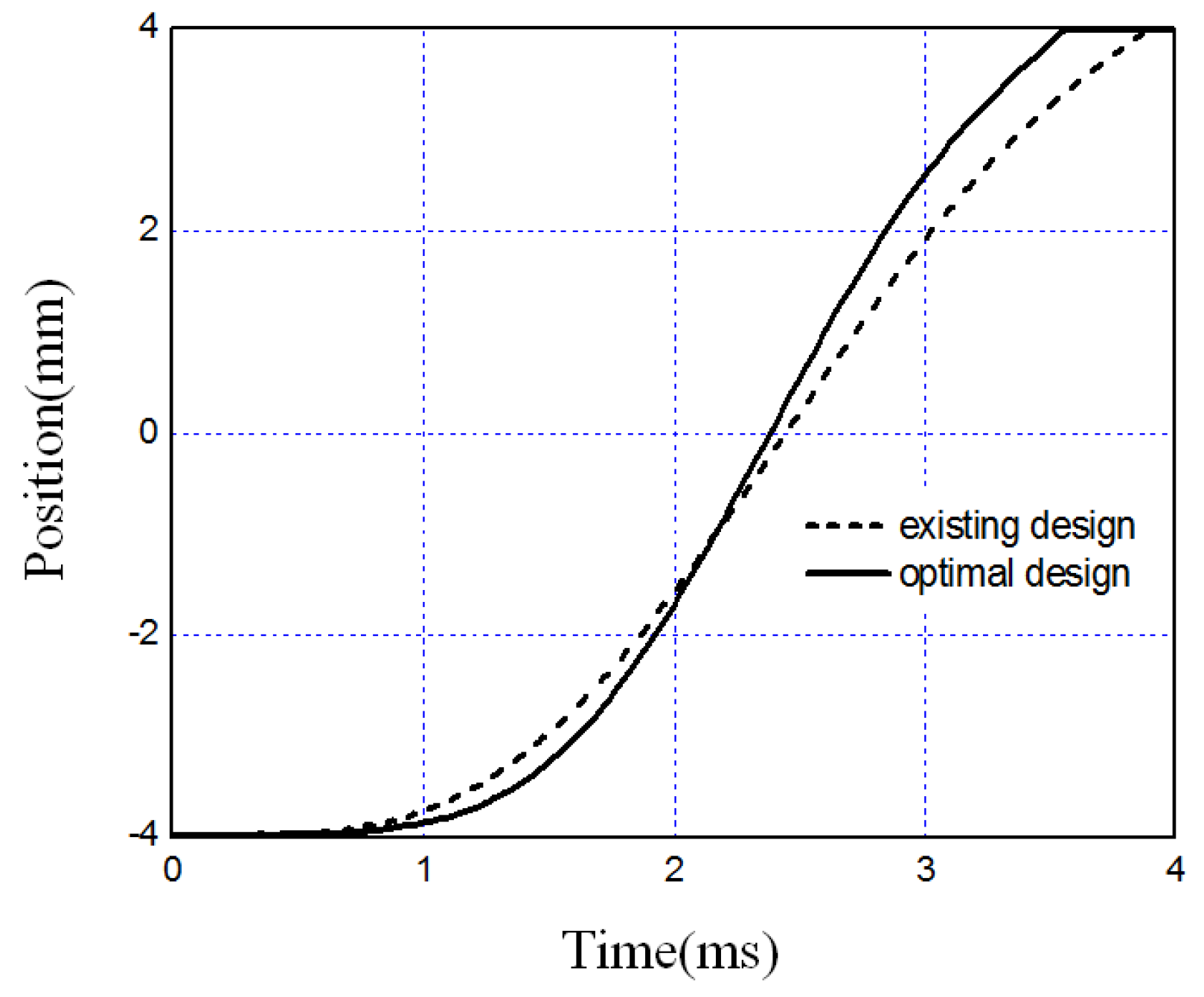
3. Dynamic Simulation
- : Magnetic vector potential in the out of plane direction;
- : Permeability of the material including armature and engine valve;
- : Magnetization of the permanent magnet;
- : Current density.
- λ: Flux linkage;
- i: Current;
- R: Resistance.
- : Damping coefficient;
- : Magnetic force;
- : Gravity force.
| Parameter | Value |
|---|---|
| Residual Induction (T) | 1.0188 |
| Coercivity (A/m) | −754,176 |
| Input voltage (V) | 200 |
| Number of turns (turns) | 200 |
| Resistance (Ω) | 1 |
| Item | Existing Design | Optimal Design |
|---|---|---|
| Transition time (ms) | 3.9 | 3.56 |
| Maximum speed (m/s) | 3.631 | 4602 |
4. Conclusions
Author Contributions
Conflicts of Interest
References
- Barkan, P.; Dresner, T. A Review of Variable Valve Timing Benefits and Modes of Operation; SAE Technical Paper Series, Paper 891676; SAE International: Warrendale, PA, USA, 1989. [Google Scholar]
- Pischinger, M.; Salber, W.; van der Staay, F.; Baumgarten, H.; Kemper, H. Benefits of the Electromechanical Valve Train in Vehicle Operation; SAE Technical Paper Series, Paper 2000-01-1223; SAE International: Warrendale, PA, USA, 2000. [Google Scholar]
- Sugimoto, G.; Sakai, H.; Umemoto, A.; Shimizu, Y.; Ozawa, H. Study on Variable Valve Timing System Using Electromagnetic Mechanism; SAE Technical Paper Series, Paper 2004-01-1869; SAE International: Warrendale, PA, USA, 2004. [Google Scholar]
- Giglio, V.; Iorio, B.; Police, G. Analysis of Advantages and of Problems of Electromagnetic Valve Actuators; SAE Technical Paper Series, Paper 2002-01-1105; SAE International: Warrendale, PA, USA, 2002. [Google Scholar]
- Mercorelli, P. A two-stage sliding-mode high-gain observer to reduce uncertainties and disturbances effects for sensorless control in automotive applications. IEEE Trans. Ind. Electron. 2015, 62, 5929–5940. [Google Scholar] [CrossRef]
- Mercorelli, P. A hysteresis hybrid extended Kalman Filter as an observer for sensorless valve control in camless internal combustion engines. IEEE Trans. Ind. Electron. 2012, 48, 1940–1949. [Google Scholar] [CrossRef]
- Mercorelli, P. A two-stage augmented extended Kalman filter as an observer for sensorless valve control in camless internal combustion engines. IEEE Trans. Ind. Electron. 2012, 59, 4236–4247. [Google Scholar] [CrossRef]
- Chladny, R.R.; Koch, C.R. Flatness-based tracking of an electromechanical VVT actuator with disturbance observer feed-forward compensation. IEEE Trans. Control Syst. Technol. 2008, 16, 652–663. [Google Scholar] [CrossRef]
- Kim, J.; Chang, J. A new electromagnetic linear actuator for quick latching. IEEE Trans. Magn. 2007, 43, 1849–1852. [Google Scholar] [CrossRef]
- Cho, D.; Woo, D.; Ro, J.; Chung, T.; Jung, H. Novel electromagnetic actuator using a permanent magnet and an inter-locking mechanism for a magnetic switch. IEEE Trans. Magn. 2013, 49, 2229–2232. [Google Scholar] [CrossRef]
- Johnson, J.M.; Rahmat-Samii, Y. Genetic algorithms in engineering electromagnetics. IEEE Antennas Propag. Mag. 1997, 39, 7–21. [Google Scholar] [CrossRef]
© 2015 by the authors; licensee MDPI, Basel, Switzerland. This article is an open access article distributed under the terms and conditions of the Creative Commons by Attribution (CC-BY) license (http://creativecommons.org/licenses/by/4.0/).
Share and Cite
Lee, S.H.; Yi, H.C.; Han, K.; Kim, J.H. Genetic Algorithm-Based Design Optimization of Electromagnetic Valve Actuators in Combustion Engines. Energies 2015, 8, 13222-13230. https://doi.org/10.3390/en81112352
Lee SH, Yi HC, Han K, Kim JH. Genetic Algorithm-Based Design Optimization of Electromagnetic Valve Actuators in Combustion Engines. Energies. 2015; 8(11):13222-13230. https://doi.org/10.3390/en81112352
Chicago/Turabian StyleLee, Seung Hwan, Hwa Cho Yi, Kyuyoung Han, and Jin Ho Kim. 2015. "Genetic Algorithm-Based Design Optimization of Electromagnetic Valve Actuators in Combustion Engines" Energies 8, no. 11: 13222-13230. https://doi.org/10.3390/en81112352