Article

A Non-Unity Torque Sharing Function for Torque Ripple Minimization of Switched Reluctance Generators in Wind Power Systems

1
Department of Electrical and Computer Engineering, Ajou University, 206, World cup-ro, Yeongtong-gu, Suwon 443-749, Korea
2
LSIS limited company, LS Tower, 127, LS-ro, Dongan-gu, Anyang-si, Gyeonggi-Do 431-848, Korea
*
Author to whom correspondence should be addressed.
Energies 2015, 8(10), 11685-11701; https://doi.org/10.3390/en81011685
Submission received: 25 August 2015 / Revised: 7 October 2015 / Accepted: 13 October 2015 / Published: 16 October 2015
(This article belongs to the Special Issue Wind Turbine 2015)

Abstract

:
This paper deals with a new torque ripple minimization method for a Switched Reluctance Generator (SRG). Although, the SRG has many advantages including simple and robust construction, and high power density as a generator, it has not been widely employed in the industry. One of the major drawbacks of the SRG is its high torque ripple that results in high noise operation of the generator. In this paper, a non-unity Torque Sharing Function (TSF) is proposed to minimize the torque ripple over a wide speed range of operation. Simulations as well as experimental results are presented to verify the effectiveness of the proposed torque ripple minimization technique.

1. Introduction

Switched Reluctance Generator (SRG) for wind power system does not have any winding and permanent magnets on its rotor. A structural feature of the SRG has many advantages over other traditional dc or ac generators. This machine has simple and robust construction, high power density, and low production cost. Because the majority of the losses occur only in its stator, the SRG is relatively easy to cool down. Hence, it can operate in high temperature and harsh environments. Furthermore, unlike conventional three phase generators such as an Induction Generator (IG) or a Permanent Magnet Synchronous Generator (PMSG), each phase of the SRG is controlled independently [1]. The magnetic independence among phases permits the machine to keep operating when phase-lacking faults occur, if a proper power converter and related control procedure are used. This leads the SRG to have a better fault tolerance ability [2,3,4,5].
Despite all of these advantages, it has not been widely employed in the industry. The total torque in the SRG is the sum of torques generated by each of the stator phases, which are controlled independently. One of the most renowned disadvantages of the SRG is its high torque ripple, which should be overcome to promote the application of the SRG. One of two major causes of high torque ripple is that the SRG has very high nonlinear characteristics due to the excessive magnetic saturation. This nonlinearity causes the torque ripple when each phase is controlled with a constant square current waveform. The other major cause of the torque ripple is the discrete nature of torque producing mechanism due to the doubly salient structure of the SRG. Therefore, the SRG has very high torque ripples during the phase commutation period when the torque production is being transferred from the outgoing phase to the incoming phase [6,7,8,9].
Since Switched Reluctance Machines (SRMs) have been dominantly used as motor drives, many studies on reducing torque ripples in a motoring mode have been carried out extensively. One of the most convenient and well-known control approaches is a Torque Sharing Function (TSF) method. In order to reduce the torque ripple, the TSF method regulates the torque production of the individual phases to distribute the reference torque among all the phases, while keeping the sum of all the individual torque references equal to the required torque. As far as the basic requirements as a TSF are satisfied, the TSF can have various different shapes. The TSFs can be classified according to the functions used to implement them. Some of the most commonly used TSFs are based on linear [6,7], sinusoidal [8], cubic, and exponential [9,10] functions.
Although the aforementioned TSFs, which are mainly developed for the motoring operation, can be directly employed to the SRG, the performance can be significantly improved, if the dynamically varying inductance with respect to the angular position of the rotor is taken into account for the generating operation. Unlike the motoring mode, each phase of the SRG starts conducting a current when the phase inductance is around its maximum value. This high inductance prevents a current from building up to a desired value rapidly. This phase current error, in turn, induces an additional torque ripple. In the literature, a new asymmetric TSF [11] that considers this problem has been introduced. However, the asymmetric TSF utilizes a piecewise linear function and is only suitable for low speed operation.
In this paper, a novel non-unity TSF will be introduced to minimize the torque ripple over a wide speed range of operation. Unlike the traditional TSFs, the sum of all the normalized phase torque references is not unity. This intentional ripple component in the torque reference behaves in such a way that it compensates the ripples in the actual output torque. In addition, a piecewise quadratic equation is used, instead of a piecewise linear one, to improve the performance further by reducing the rate-of-change of the current reference. To find optimal parameters for the non-unity TSF at different operating speeds, the sequential quadratic programming method [12,13] is used. The effectiveness and resulting improvement in the performance of the proposed torque minimization technique will be demonstrated through simulation results and experimental results.

2. Switched Reluctance Generator and Torque Sharing Function

2.1. Theoretical Background of the Switched Reluctance Generator Eletromechanics

Before introducing a new torque minimization technique, a brief analysis of the SRG’s electromechanics will be given in this section. 
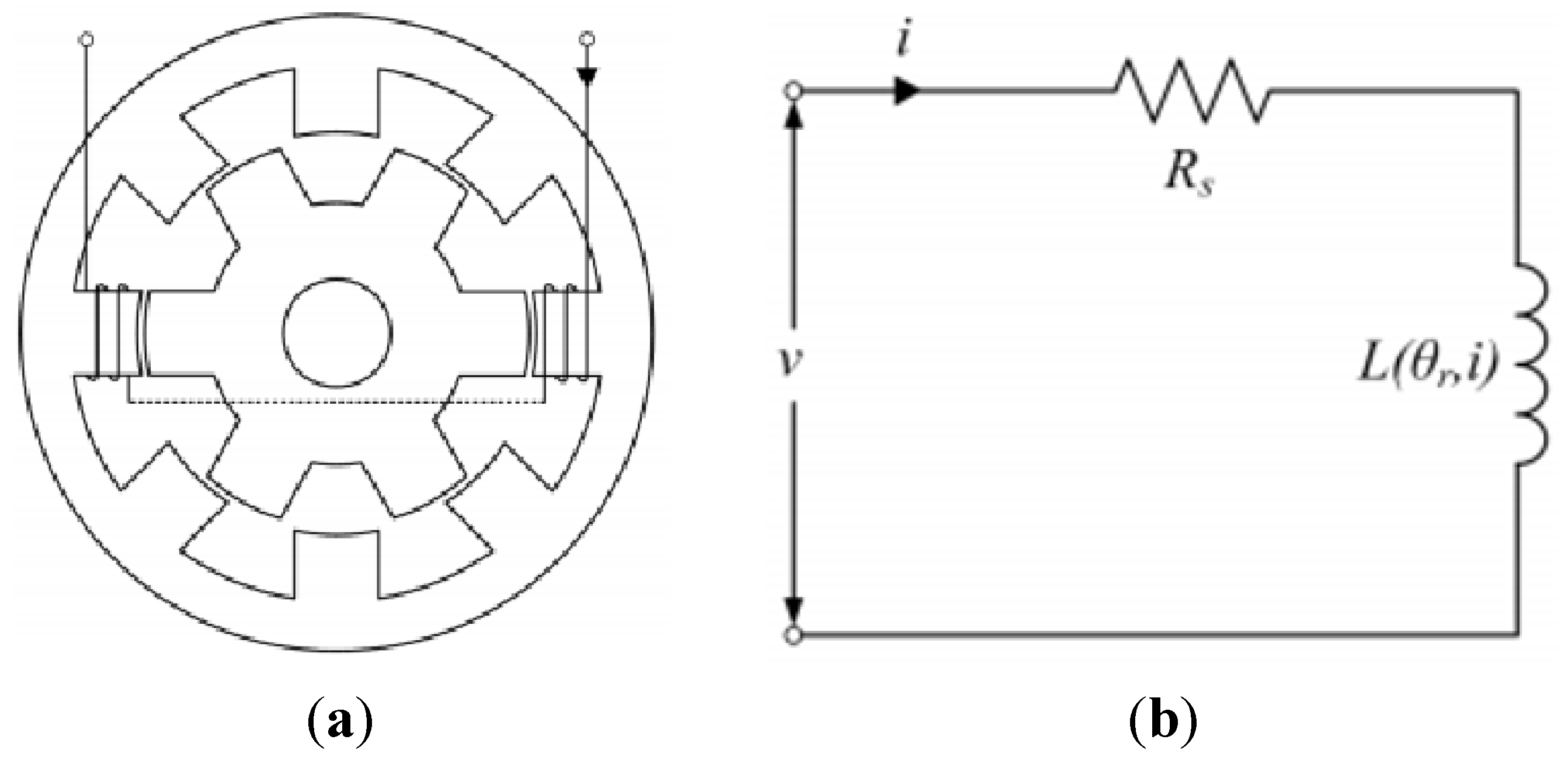
Figure 1a shows the cross-sectional profile of a conventional four phase 8/6-pole SRG and Figure 1b shows its equivalent circuit of one phase winding. In Figure 1a, only one phase winding is shown for the sake of simplicity. Both the stator and the rotor of the SRG are usually made of steel laminations. While each salient pole on the stator has a concentrated winding, the rotor does not have any winding or permanent magnet, but a chunk of laminated steel shaped like a gear. This structural feature makes the SRG simple, robust, and low-cost. The equivalent circuit of one phase winding can be simplified with a phase resistance, Rs, connected to a phase inductance, Lr, i) in series. It is worth noting that the inductance is a function of the rotor position, θr, and the phase current, i.
Figure 1. Four phase 8/6-pole Switched Reluctance Generator (SRG): (a) cross-sectional profile; (b) equivalent circuit of one phase winding.
Energies 08 11685 g001
The voltage equation of one phase winding of the SRG can be expressed as:
v = R s i + ( θ r , i ) d t
where λ(θr, i) = Lr, i)i is the phase flux linkage. Using the relationship between the fiux linkage, and the inductance and current, this voltage equation can be rewritten as:
v = R s i + d [ L ( θ r , i ) i ] d t = R s i + L ( θ r , i ) d i d t + d L ( θ r , i ) r ω r i
where ωr is the angular speed of the rotor. In the above equation, the terms on the most right-hand side represent the resistive voltage drop, the inductive voltage drop, and the back-electromotive force (back-emf), respectively. It is worth noting that the voltage equation is also a function of the rotor position and the phase current. Furthermore, it is a nonlinear equation where two state variables (here, the angular speed, ωr, and the phase current, i) are multiplied together.
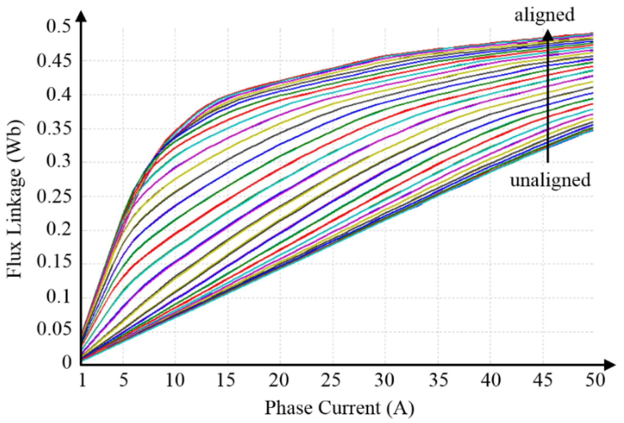
The electromagnetic torque equation of the SRG can be derived from the magnetization characteristics of one phase winding, which can be achieved through an experimental test or a finite element analysis (FEA). Figure 2 shows the magnetization characteristics of the SRG used in this paper. The uppermost line represents the flux linkage when the stator and the rotor are aligned. This line exhibits the high magnetic saturation characteristic of the flux. On the other hand, the lowermost line represents the flux linkage when the stator and the rotor are unaligned completely. This line does not exhibit the saturation characteristic because of a large air gap between the stator and rotor poles.
Figure 2. Magnetization characteristics of the 1 kW 8/6-pole SRG.
Energies 08 11685 g002
The electromagnetic torque can be calculated by finding the partial derivative of the magnetic co-energy with respect to the angular position of the rotor [14]. The torque equation of the SRG can be expressed as:
T e ( θ r i ) = 1 2 i 2 d L ( θ r , i ) r
This torque is dependent upon the rotor position and the phase current in a nonlinear way because the state variables are multiplied together (here, the phase current, i, is squared). Furthermore, the torque is proportional to the square of the phase current and to the partial derivative of the inductance with respect to the angular position of the rotor.
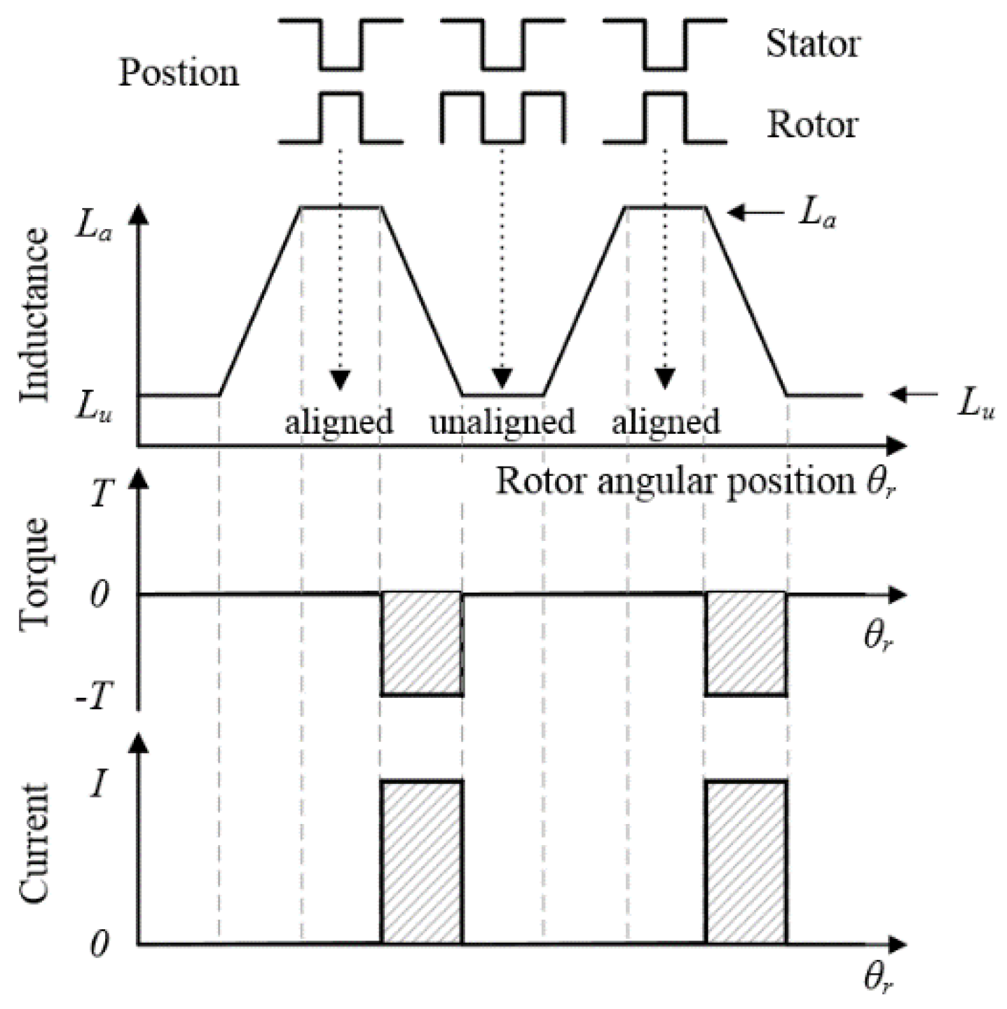
Figure 3 shows the torque relationship between an idealized inductance profile and a phase current. The idealized inductance profile can be obtained by neglecting the effect of the magnetic saturation. It varies linearly with respect to the overlap between the stator and rotor poles. As can be seen from the figure, the inductance has its maximum value, La, when the poles of the stator and rotor are fully aligned, whereas it has its minimum value, Lu, when the poles are completely unaligned. If a constant current is drawn in the phase only during the negative slope of the inductance profile, the negative torque can be generated. Therefore, if each phase produces torque in sequence at proper instants, the SRG can produce continuous unidirectional torque.
Figure 3. Torque relationship between the idealized inductance profile and the phase current.
Energies 08 11685 g003

2.2. Characteristics of Wind Turbine

The required output power of SRG is considered according to the shaft speed with wind turbine [15,16].
The mechanical torque produced by a wind turbine is given by:
T m = πρ C t ( λ , β ) R 3 v 2 / 2
where the parameters C t ( λ , β ) , ρ , R , β , v , and λ are, respectively, torque coefficient, air density, blade radius, blade pitch angle, wind velocity, and tip-speed ratio.
Power captured from the wind turbine is obtained as seen in Equation (6) and λ is the tip-speed ratio which can be defined as:
λ = ω m R / v
P m = πρ C P ( λ , β ) R 2 v 3 / 2
where ωm represents the rotational speed of the blades, C P ( λ , β ) denotes the power coefficient, which is directly determined by λ when the blade pitch angle is fixed. It is desired to verify the effectiveness of the proposed torque ripple minimization technique for higher wind speed by considering the power captured from the wind turbine.

2.3. Main Causes of Torque Ripples

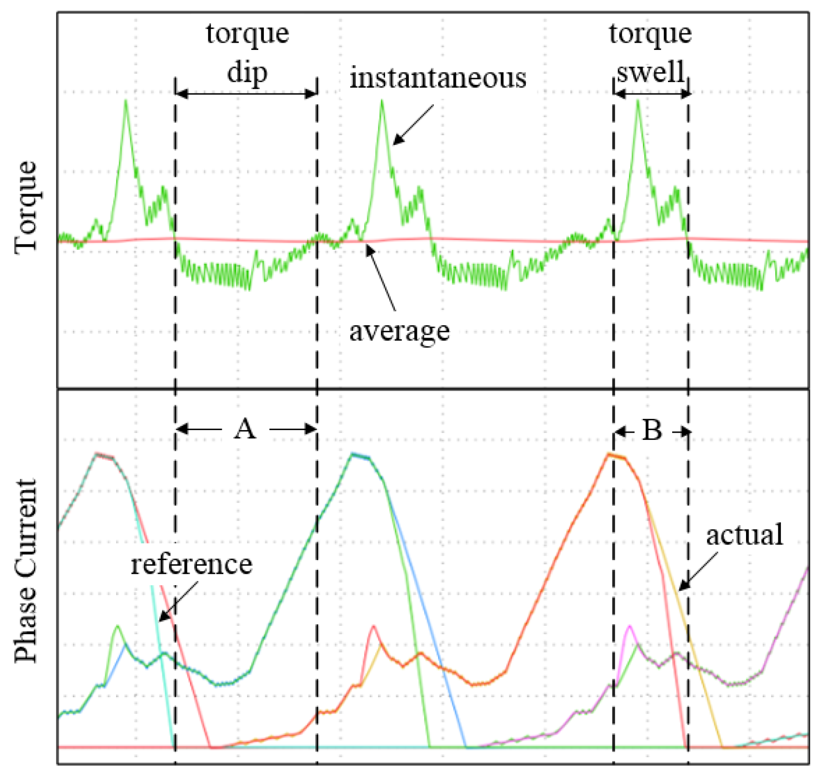
There are several main causes of the torque ripples in the SRG: inherent nonlinearity, phase commutation, and current switching. If the effect of the magnetic saturation is not neglected, the inductance profile does not vary linearly with respect to the overlap between the stator and rotor poles anymore. Hence, even if the each phase is controlled to draw a constant current, the produced torque is not constant anymore. This nonlinearity usually causes a torque swell when a single phase is solely in charge of producing the entire toque required. Therefore, the phase current should be shaped according to the nonlinear torque–angle–current (T–θri) characteristics of the SRG to produce a constant torque.
Another major cause of the torque ripple is the discrete nature of torque producing mechanism due to the doubly salient structure of the SRG. Unlike traditional three-phase generators such as an IG or a PMSG, the SRG does not utilize a smooth rotating magnetic field. Each phase of the SRG is responsible for producing torque independently using magnetic reluctance force. Therefore, the SRG has a very high torque ripple, usually a torque dip, during the phase commutation period when the torque production is being transferred from the outgoing phase to the incoming phase.
The other cause of the torque ripple is the current switching. The current in each phase should be controlled to track its desired value by switching the power semiconductor switches connected to the phase. As a consequence, these current ripples cause additional torque ripples at the switching frequency. The magnitude of the torque ripple depends on the switching frequency and the operating conditions such as an input voltage, a load torque, and/or an operating speed. If the phase current is controlled by a hysteresis current controller as in this paper, the magnitude of the torque ripple is significantly dependent upon the size of its hysteresis band.

2.4. Traditional Torque Sharing Functions

The TSF controls the instantaneous torque of the individual phases by profiling the phase currents optimally during a phase overlapping period between the outgoing and incoming phases. 
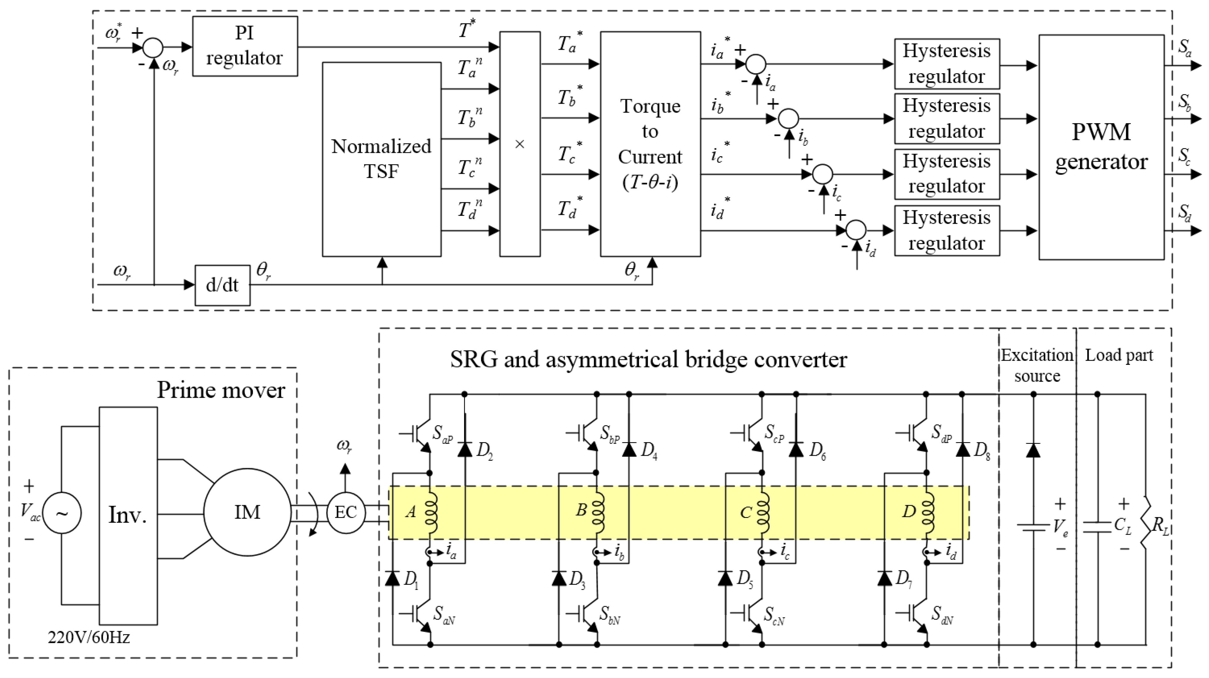
Figure 4 shows the overall SRG control system including the TSF method. When the prime mover operates at the different speed, ωr can be obtained from the encoder of the rotor. The result of speed control produces the total torque required (T*). The normalized TSF block produces torque references for the individual phases based on the angular position of the rotor. These normalized torque references are multiplied with the total torque required (T*) so that the actual torque reference for each phase is obtained separately.
Figure 4. Overall torque control scheme of the Torque Sharing Function (TSF) method.
Energies 08 11685 g004
Each torque reference is, then, converted into a current reference through the 2-D lookup table of the torque–angle–current (T–θri) characteristics, which can be directly obtained from the magnetization characteristics of the SRG. To avoid storing large lookup table data, an invertible torque function [17] can be used instead. Finally, the hysteresis current regulators produce switching signals for the driving power converter based on the reference currents and the measured currents. All switching signals are produced through the PWM block.
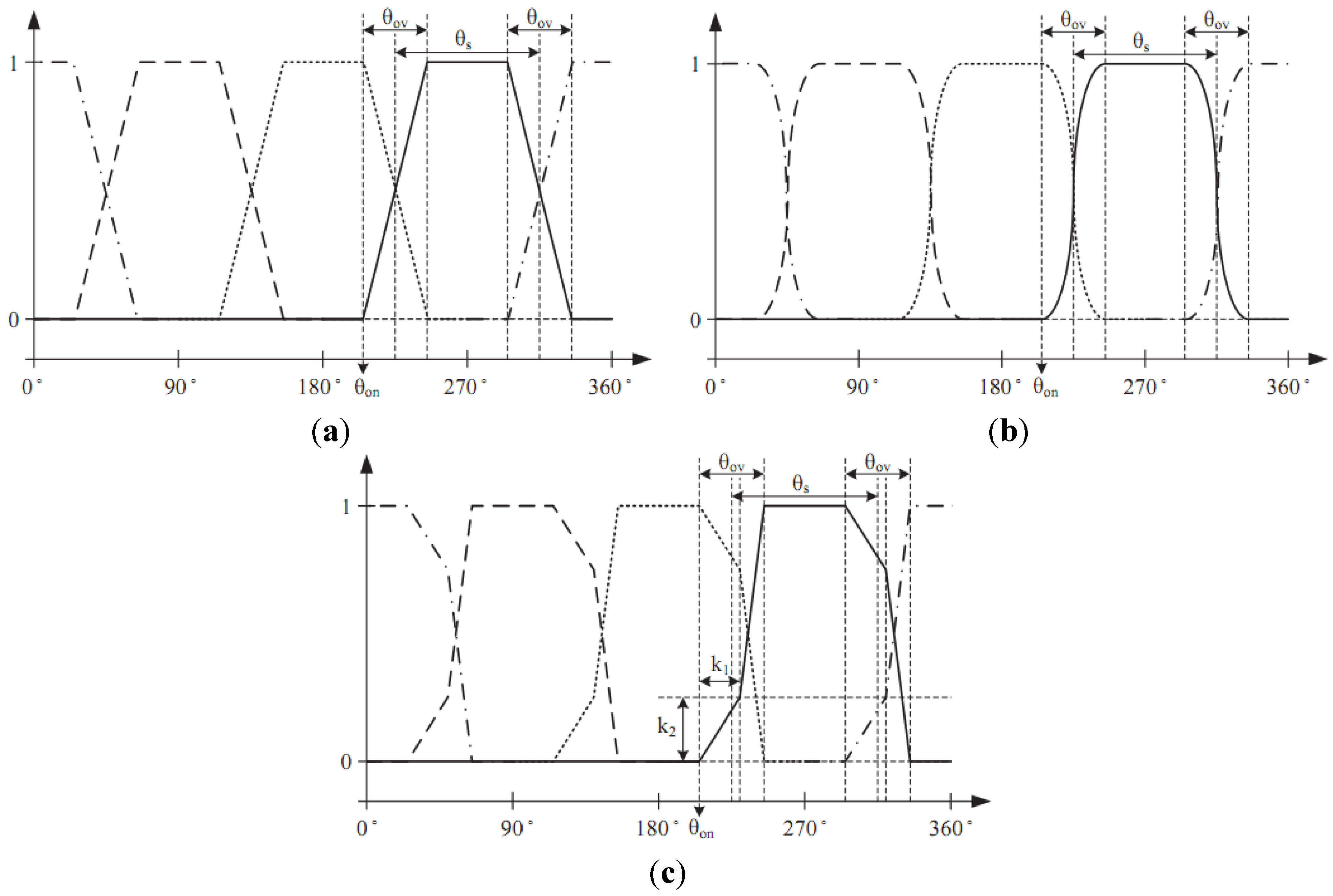
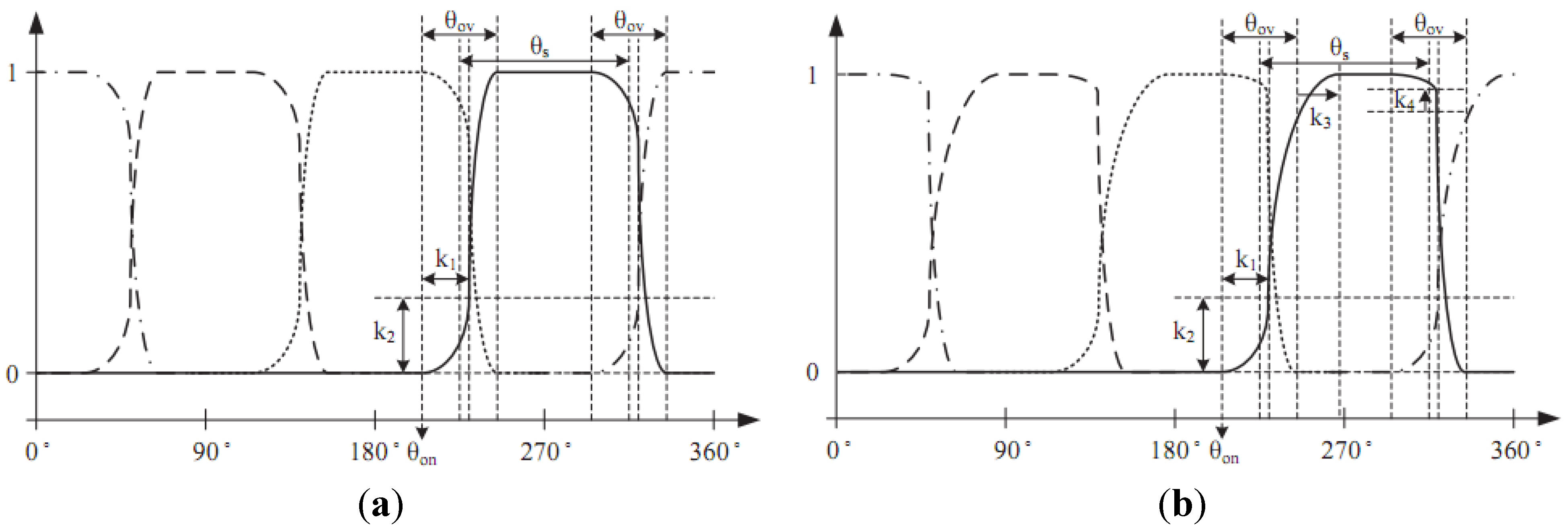
According to the torque sharing curve used, the traditional TSFs can be classified as linear or nonlinear TSFs as shown in Figure 5a,b. The nonlinear TSFs further can be classified into sinusoidal, cubic, and exponential TSFs. By optimizing the turn-on angle, θon, and the overlapping angle, θov, the torque ripple can be minimized.
Figure 5. Typical profiles: (a) linear TSF; (b) nonlinear TSF; (c) asymmetric TSF.
Energies 08 11685 g005
Although these TSFs have been dominantly developed for the motoring operation, they can be directly employed for the generating operation. However, if the unique characteristic of the SRG is taken into account, the performance of the TSF method can be enhanced further. Unlike the motoring mode, each phase of the SRG starts being energized when the stator and the rotor are aligned, and deenergized when they are unaligned. In other words, the phase inductance is at its maximum value when the phase starts conducting a current. This high inductance prevents a current from tracking a reference value accurately, especially when the rate-of-change of the reference current is large. This phase current error, in turn, induces additional torque ripples. In order to solve this problem, an asymmetric TSF that utilizes a piecewise linear curve to lower the rate-of-change of the current reference has been proposed [9], as shown in Figure 5c. By introducing two more control parameters (k1 and k2), the asymmetric TSF utilizes two different slopes during the phase overlapping period. It is worth noting that the stroke angle, θs, is determined according to the number of the phases, Nph, and the number of the rotor poles, Nr, as below:
θ s = 360 ° N ph N r
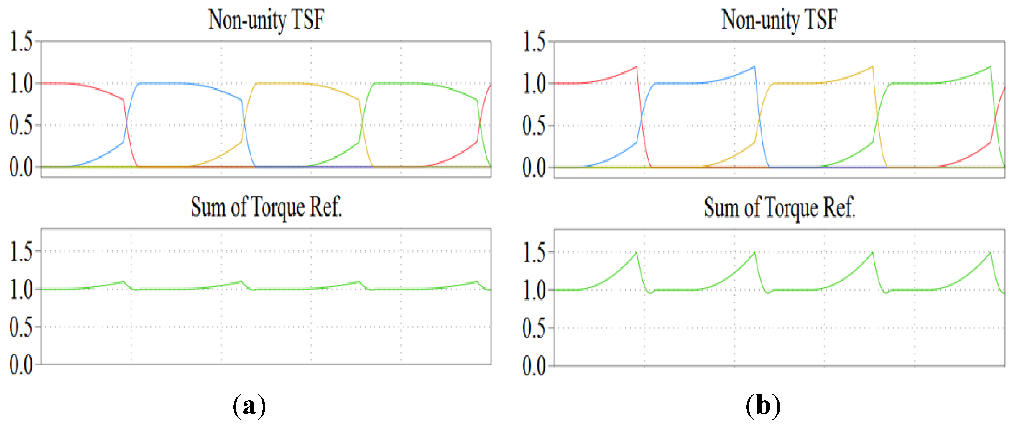
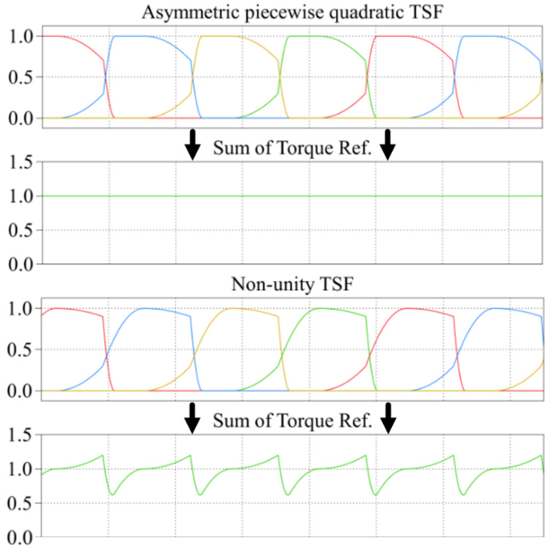
Even though the TSFs have different shapes, they all satisfy a basic requirement as a TSF: the sum of all the normalized phase torque references is always equal to unity. Furthermore, they all assume that the actual current is well controlled to track its reference value. Therefore, the TSF technique is not applicable to the single-pulse voltage mode.

3. Proposed Non-Unity Torque Sharing Function

Although the asymmetric TSF for the SRG has satisfactory performance at low speeds, its performance deteriorates as an operating speed increases. In this section, the torque ripples at high speeds will be analyzed and a novel non-unity TSF will be introduced to minimize the torque ripple over a wide speed range of operation.

3.1. Causes of Torque Ripples at High Speeds

Figure 6 shows the waveforms of the produced torque and the phase current and its reference value at the high speed of 1000 rpm when the asymmetric TSF is used.
Figure 6. Waveforms of the produced torque and the phase current at the high speed of 1000 rpm.
Energies 08 11685 g006
At the beginning of the current conduction in each phase, the rate-of-change of the current reference is still much higher than that of the actual current due to the high phase inductance. During this period, this lack of actual current induces a dip in the output torque (region A). On the other hand, at the end of the current conduction, the actual current cannot decrease to zero as fast as the reference value at the high speed even though the phase inductance is much lower. In addition, the current references are created higher actual currents according to torque reference of asymmetric TSF. This excessive current, in turn, induces a torque swell as shown in the figure (region B). These two torque ripple components prevent the TSF techniques from having a wide speed range of operation.

3.2. A Non-Unity Piecewise Quadratic TSF

In order to improve the performance and to extend the operating speed range of the asymmetric TSF, a new non-unity piecewise quadratic TSF is proposed here. Among the traditional symmetric TSFs (linear, sinusoidal, cubic, and exponential), the nonlinear TSFs usually have better performance than the linear TSF because the nonlinear TSFs tend to have a lower rate-of-change of the reference current. This idea is also applicable to the asymmetric TSF. Therefore, as shown in Figure 7a, a piecewise quadratic curve is applied to the proposed TSF to lower the rate-of-change of the reference current especially for the beginning of the current conduction. In the proposed TSF, two additional control parameters (k3 and k4) are introduced as shown in Figure 7b. k3 makes the angle, where the TSF curve reaches unity, retreat and induces a dip in the total sum of all the individual torque references. On the other hand, k4 slows the decrease of the reference torque so that it causes a swell in the sum.
Figure 7. Profiles: (a) the asymmetric TSF with a piecewise quadratic curve; (b) the proposed non-unity TSF.
Energies 08 11685 g007
The proposed TSF for is defined as follows:
T a , b , c , d n = { 0 0 θ r < θ on f rise1 ( θ r ) θ r < θ on + k 1    f rise2 ( θ r ) θ r on + θ ov + k 3 1 θ r < θ off θ ov f fall1 ( θ r ) θ r < θ off θ ov + k 1 f fall2 ( θ r ) θ r < θ off 0 θ r > θ off
As shown in Figure 7b, in order to reduce the torque ripple, the proposed TSF form can change the four parts according to k1k4. The function T a , b , c , d n includes four parts as:
f rise1 ( θ r ) = k 2 ( θ r θ on ) 2
f rise2 ( θ r ) = b t ( x 1 2 2 x 1 k 3 ) + S ratio
f fall1 ( θ r ) = a t ( θ r θ off + θ ov ) 2 + 1
f fall2 ( θ r ) = b t1 ( x 1 2 2 x 1 θ sca_c ) + ( 1 S ratio_t )
where:
k 1 = θ ov S change_ratio
k 2 = S ratio / k 1 2
k 3 = θ ov k 1 + on tune
k 4 = S ratio off tune
x 1 = θ r θ on k 1
b t = ( S ratio 1 ) / k 3 2
a t = k 4 / k 1 2
b t 1 = ( 1 k 4 ) / ( θ ov k 1 ) 2
T a , b , c , d * can be obtained through T a , b , c , d n and T * which is calculated from the speed control in Figure 4. In order to apply the nonlinear characteristic of SRG, T a , b , c , d * is applied to 2-D lookup table of the torque–angle–current (T–θri). The parameters used to compute k1k4 which are S change_ratio , S ratio , on tune , and off tune . They are considered as the initial parameters of TSF.
In order to verify the effectiveness of k3 and k4, these values are changed from 1% to 50%, while k1 and k2 are kept constant. Figure 8 shows the changed value of k3 and k4. It can be seen at Figure 8b, that the peak sum of torque reference increase. Therefore, the torque ripple can be easily reduced due to the changing of k3 and k4 at the high speed range. Hence, the total sum of all the individual torque references is not unity anymore as shown in Figure 9. These deliberately inserted ripple components in the torque reference behave in such a way that it compensates the actual ripples in the output torque during the high speed operation. Therefore, by optimizing six control parameters (θon, θov, k1, k2, k3, and k4) at each operating speed, the torque ripple can be minimized significantly over a wider speed range of operation. The optimization can be performed using various optimization algorithms such as a least square method or a genetic algorithm (GA).
Figure 8. Sum of torque reference according to k3 and k4: (a) 10%; (b) 50%.
Energies 08 11685 g008
Figure 9. Torque references for the individual phases and the total sum of them.
Energies 08 11685 g009
In this paper, a sequential quadratic programming (SQP) method [12,13] is used and it can be easily accessed through the function named “fmincon” in Matlab. By extending the SQP method, consider the equality constrained problem.
min f ( x ) subject to  h ( x ) = 0
where x = [ θ on , θ ov , k 1 , k 2 , k 3 , k 4 ] T is the design variable vector, f ( x ) is the objective function, and h ( x ) is the equality constraints which is the speed range.

4. Simulations

Simulations have been performed to verify the effectiveness of the proposed TSF technique using Matlab/Simulink. To compare the performance of the proposed TSF with that of the conventional asymmetric TSF, simulations for both the asymmetric and non-unity TSFs have been performed in parallel at various operating speeds. The SRG model used in this simulation is a 1 kW, 4-phase, 8/6-pole generator whose magnetization characteristics are shown in Figure 2. Hysteresis control is used for the current controller and the hysteresis band is set to 0.2 A for all the operating speeds. The SRG is controlled by a conventional asymmetric half-bridge converter using 40 Vdc.
Figure 10, Figure 11 and Figure 12 show simulation result at various operating speeds. Table 1 summarizes the simulation results according to the torque and phase current characteristics, respectively. As it can be seen from Figure 10, the torque ripples at 300 rpm are dominantly caused by the current switching for both TSFs. The magnitude of the torque ripples during the commutation period is kept within that of the torque ripples caused by the switching. The asymmetric and non-unity TSF have almost identical performance at the low speed of 300 rpm. Using the proposed TSF, only 1.56% of the toque ripple is reduced comparing to that of the asymmetric TSF at this speed.
Figure 10. Simulation results at 300 rpm: (a) asymmetric TSF; (b) non-unity TSF.
Energies 08 11685 g010
Figure 11. Simulation results at 600 rpm: (a) asymmetric TSF; (b) non-unity TSF.
Energies 08 11685 g011
Figure 11 shows the simulation results when the SRG is operating at 600 rpm. As the speed increases, the torque ripples during the phase commutation become observable. Since the asymmetric TSF does not have the ability to compensate the torque ripples caused by errors in the phase currents at the beginning and end of the conduction, the torque dips and swells arise as explained in Section 3.1. The high frequency switching torque ripples are still superimposed on these torque dips and swells. On the other hand, the proposed TSF tries to keep the output torque ripples as small as possible using its compensating ability. Using the non-unity TSF, 35.33% of the toque ripple is reduced at this speed.
As shown in Figure 10 and Figure 11, the performance of both asymmetric TSF and non-unity TSF achieve similar results according to the torque and current. This is because of the rate-of-change of the reference current which is lower especially in the beginning of the current conduction at low speed.
If the operating speed of the SRG is increased even more, the effectiveness of the proposed TSF becomes more evident. Figure 12 shows the simulation results when the SRG is operating at 1000 rpm. Now, it can be observed that the magnitudes of these torque dips and swells are much bigger than that of torque ripples caused by the current switching. The asymmetric TSF has the total torque ripple of 66.7%, whereas the proposed non-unity TSF has 13.04%. Therefore, the torque ripple is reduced by 80.45% at this speed. Using the non-unity TSF, the magnitude of the torque ripples is kept almost within that of the torque ripple caused by the current switching.
Table 1. Torque results.
Torque Sharing Function (TSF) algorithmTorqueRPM
300 rpm600 rpm1000 rpm
Asymmetric TSFMax. (N·m)0.923.259.286
Min. (N·m)0.281.655.09
Average (N·m)0.672.786.29
Ripple (%)95.5257.5566.7
Non-unity TSFMax. (N·m)0.923.1936.61
Min. (N·m)0.292.1625.79
Average (N·m)0.672.776.29
Ripple (%)94.0237.2213.04
Torque ripple decrease (%)1.5635.3380.45
Figure 13 shows the torque control according to the variable torque. When the asymmetric TSF is applied to the SRG, it has a higher torque ripple when compared to the non-unity TSF. It can be concluded that the torque control using the non-unity TSF in variable torque could be a good candidate in case of wind turbine.
Figure 12. Simulation results at 1000 rpm: (a) asymmetric TSF; (b) non-unity TSF.
Energies 08 11685 g012
Figure 13. Torque control according to the variable torque: (a) asymmetric TSF; (b) non-unity TSF.
Energies 08 11685 g013

5. Experimental Results

Figure 14 shows the experiment setup of the 1 kW, four phase 8/6 SRG, used to verify the proposed algorithm. The 3.75 kW three-phase squirrel-cage induction motor is used as a prime mover. The experiment is repeated at a constant speed of 300 rpm, 600 rpm, and 1000 rpm during the experiment. DSP controller TMS320F28335 from Texas Instruments is used for digital implementation of the proposed TSF. Current hysteresis band is set to be 0.2 A, and dc-link voltage is set to 40 Vdc. The sampling time of the digital controller in the experimental setup is set to 50 μs. The capacitor and the resistance are used to deal with the generation energy. The resistance is set at 6.15 Ω in order to fulfill the output voltage requirements. The nonlinear torque–angle–current (T–θri) characteristics of SRG are stored as look up tables in DSP. Current reference is estimated from these look-up tables by measuring the torque and rotor position, and converted into an analog signal through digital-to-analog conversion chip in the hardware. Torque reference for the experimental is set to a smaller value compared the simulation conditions. It is possible to confirm the proposed using a small current reference and torque reference.
Figure 14. Experimental setup of SRG drive.
Energies 08 11685 g014
Figure 15 shows experimental results of asymmetric TSF and non-unity TSFs operating at 300 rpm. The average torque is 0.25 N·m and sampling time is 50 us in this experiment. The asymmetric and non-unity TSF have comparable torque ripple at the low speed of 300 rpm. The torque ripples of asymmetric TSF and non-unity TSF at 300 rpm is around 76% and 72% compared to 95.5% and 94% torque ripples in simulation results in Figure 10. Using the proposed TSF, 5.2% of the torque ripple is reduced comparing to that of the asymmetric TSF at this speed.
Experimental results when the SRG is operating at 600 rpm are shown in Figure 16. The average torque is 0.5 N·m in this experiment. The torque references of asymmetric TSF are similar to non-unity TSF at 300 rpm. However, the shape of the torque reference changes at 600 rpm. When comparing the simulation result and experiment result, the current references are similar. The torque ripples of asymmetric TSF and non-unity TSF at 600 rpm is around 42% and 40% compared to 57.5% and 37.2% torque ripples in simulation results in Figure 11. Using the proposed TSF, 4.7% of the torque ripple is reduced comparing to that of the asymmetric TSF at this speed.
As shown in Figure 17, when the operating speed of the SRG is increased even more, asymmetric TSF occurs torque dips and swells. The torque ripples of asymmetric TSF and non-unity TSF at 1000 rpm is around 80% and 22% compared to 66.7% and 13.03% torque ripples in simulation results in Figure 12. In addition to, 71.67% of the torque ripple is reduced comparing to that of the asymmetric TSF at this speed. Therefore, the application of non-unity TSF in wind power system is verified by these simulation and experiment.
Figure 15. Experiment results at 300 rpm: (a) asymmetric TSF; (b) non-unity TSF.
Energies 08 11685 g015
Figure 16. Experiment results at 600 rpm: (a) asymmetric TSF; (b) non-unity TSF.
Energies 08 11685 g016
Figure 17. Experiment results at 1000 rpm: (a) asymmetric TSF; (b) non-unity TSF.
Energies 08 11685 g017

6. Conclusions

In this paper, a new non-unity TSF for the SRG at high speeds has been presented. As the name implies, its sum of all the individual phase torque references (normalized) is not unity. The ripple components are inserted deliberately into the torque reference by introducing two additional control parameters. These ripple components in the torque reference behave in such a way that they cancel out the actual ripples in the output torque during high-speed operation. In addition, a piecewise quadratic curve is employed to improve the performance further by reducing the rate-of-change of the current reference. The simulation results and the experimental results show that, even though the conventional asymmetric TSF has satisfactory performance at low speeds, the torque ripples can be reduced significantly by employing the proposed TSF at high speeds. Therefore, the non-unity TSF can minimize the torque ripples over a wider speed range of operation than the conventional TSFs.

Acknowledgments

This work was supported by the Human Resources Development of the Korea Institute of Energy Technology Evaluation and Planning (KETEP) grant funded by the Korea government Ministry of Knowledge Economy (No. 20134030200310) and by Basic Science Research Program through the National Research Foundation of Korea (NRF) funded by the Ministry of Education (2013R1A1A2A10006090).

Author Contributions

Kyo-Beum Lee provided guidance and supervision. Kiwoo Park conceived the idea of this paper and performed the simulation. Hye-Ung Shin implemented the main research, performed the experiment, wrote the paper and revised the manuscript as well. All authors have equally contributed to the simulation analysis, experiment and result discussions.

Conflicts of Interest

The authors declare no conflict of interest.

References

  1. Chwa, D.K.; Lee, K.B. Variable Structure Control of the Active and Reactive Powers for a DFIG in Wind Turbines. Ind. Appl. 2010, 46, 2545–2555. [Google Scholar] [CrossRef]
  2. Torrey, D.A. Switched reluctance generators and their control. Ind. Electron. 2002, 49, 3–14. [Google Scholar] [CrossRef]
  3. Kioskeridis, I.; Mademlis, C. Optimal efficiency control of switched reluctance generators. Power Electron. 2006, 21, 1062–1072. [Google Scholar] [CrossRef]
  4. Chang, Y.; Liaw, C. On the design of power circuit and control scheme for switched reluctance generator. Power Electron. 2008, 23, 445–454. [Google Scholar] [CrossRef]
  5. Ro, H.S.; Kim, D.H.; Jeong, H.G.; Lee, K.B. Tolerant Control for Power transistor Faults in Switched Reluctance Motor Drives. Ind. Appl. 2015, 51, 3187–3197. [Google Scholar] [CrossRef]
  6. Schramm, D.S.; Williams, B.W.; Green, T.C. Torque ripple reduction of switched reluctance motors by phase current optimal profiling. In Proceedings of the Power Electronics Specialists Conference (PESC), Toledo, Spain, 29 June–3 July 1992; pp. 857–860.
  7. Ro, H.S.; Lee, K.G.; Lee, J.S.; Jeong, H.G.; Lee, K.B. Torque Ripple Minimization Scheme Using Torque Sharing Function Based Fuzzy Logic Control for a Switched Reluctance Motor. J. Electr. Eng. Technol. 2015, 10, 118–127. [Google Scholar] [CrossRef]
  8. Husain, I.; Ehsani, M. Torque ripple minimization in switched reluctance drives by PWM current control. Power Electron. 1996, 11, 83–88. [Google Scholar] [CrossRef]
  9. Xue, X.D.; Cheng, K.W.E.; Ho, S.L. Optimization and evaluation of toque-sharing-functions for torque ripple minimization in switched reluctance motor drives. Power Electron. 2009, 24, 2076–2090. [Google Scholar] [CrossRef]
  10. Vujicic, V.P. Minimization of torque ripple and copper losses in switched reluctance drive. Power Electron. 2012, 27, 388–399. [Google Scholar] [CrossRef]
  11. Moreau, L.; Machmoum, M.; Zaim, M.E. Control and minimization of torque ripple in switched reluctance generator. In Proceeding of the 2005 European Conference on Power Electronics and Applications, Dresden, Germany, 11–14 September 2005; pp. 1–8.
  12. Fletcher, R. Practical Methods of Optimization, 2nd ed.; Wiley: Hoboken, NJ, USA, 2000. [Google Scholar]
  13. Li, Z.; Papalambros, P.Y.; Volakis, J.L. Designing broad-band patch antennas using the sequential quadratic programming method. Trans. Antennas Propag. 1997, 45, 1689–1692. [Google Scholar]
  14. Krishnan, R. Switched Reluctance Motor Drives Modeling, Simulation, Analysis, Design, and Application; CRC Press: Boca Raton, FL, USA, 2001. [Google Scholar]
  15. Vujicic, V.P. Modeling of a switched reluctance machine based on the invertible torque function. Magnetics 2008, 44, 2186–2194. [Google Scholar] [CrossRef]
  16. Choi, D.W.; Byun, S.I.; Cho, Y.H. A Study on the Maximum Power Control Method of Switched Reluctance Generator for Wind Turbine. Magnetics 2014. [Google Scholar] [CrossRef]
  17. Morandin, M.; Fornasiero, E.; Bolognani, S.; Bianchi, N. Torque and Power Rating of a Wind-Power PM Generator Drive for Maximum Profit-to-Cost Ratio. Ind. Appl. 2013, 49, 866–872. [Google Scholar] [CrossRef]

