
Hybrid Multi-Agent Control in Microgrids: Framework, Models and Implementations Based on IEC 61850

Abstract
:1. Introduction
2. Design of Hybrid Multi-Agent Control Model Based on Hierarchical Control Framework in Microgrids
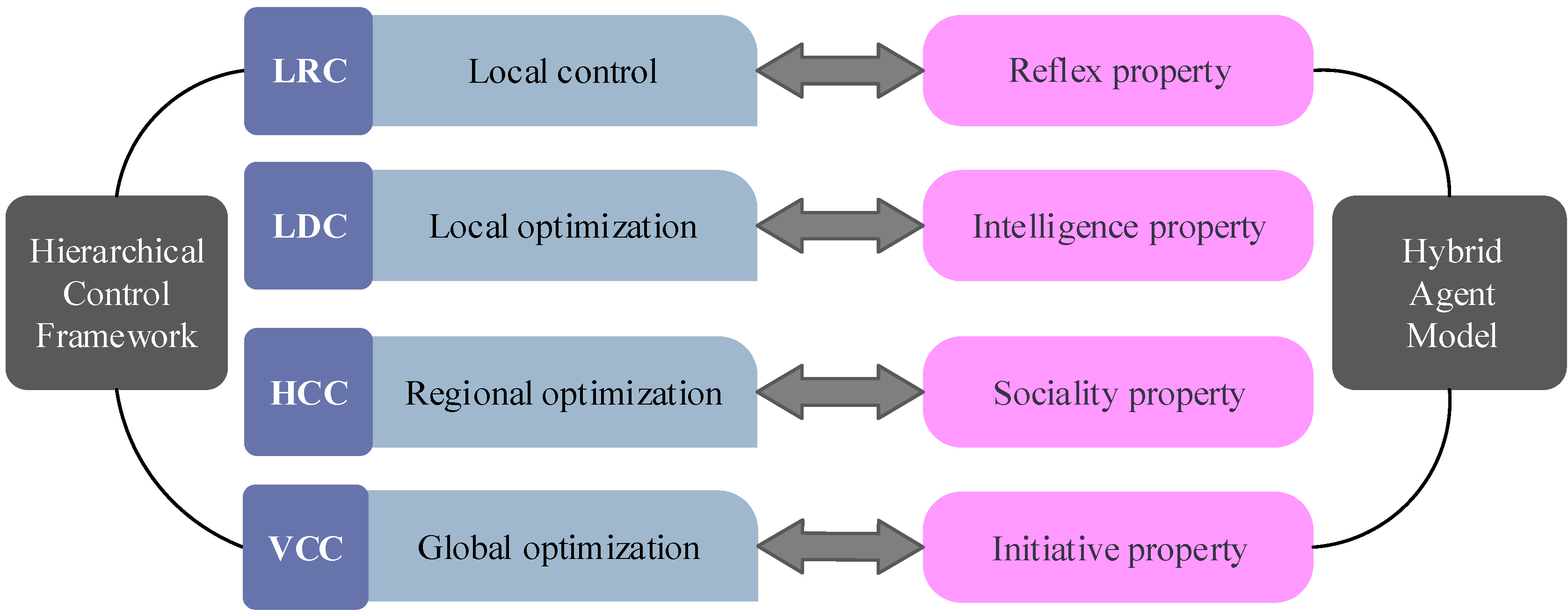
2.1. Hierarchical Control Framework in Microgrids
- (1)
- At the local reaction control (LRC) level, CU implements the basic functions according to local electricity information (e.g., the magnitudes of voltage and current at the point of coupling between CU and microgrids). LRC indicates CU can work independently without external control.
- (2)
- At the local decision control (LDC) level, CU implements some optimizations without external control. LDC indicates CU can autonomously regulate the control strategies, references or parameters to work more efficiently and economically.
- (3)
- At the horizontal cooperation control (HCC) level, CU communicates and cooperates with others. HCC indicates CU can participate in coordinated control. With the advantages of the cooperation among CUs, some more complex and optimized operations can be implemented, which is superior to LDC and LRC especially when there is a large disturbance.
- (4)
- At the vertical cooperation control (VCC) level, there is a central controller (e.g., microgrid control center (MGCC) or microgrid energy management system, which distributes operation commands to other CUs with the global optimization. VCC indicates CU can be dispatched, which could make microgrids operate most efficiently and economically under the control of central controller. The response delay of VCC is generally the longest among the four levels, due to the complex calculation for the global optimization.
2.2. Properties of Hybrid Multi-Agent Control Model
- (1)
- Reflex property of HAM is related to LRC in HCF. It means that the local controls of CU will be implemented by the reflex control strategies of HAM.
- (2)
- Intelligence property of HAM is related to LDC in HCF. It means that the local optimizations of CU will be implemented by the intelligent control strategies of HAM.
- (3)
- Sociality property of HAM is related to HCC in HCF. It means that the coordinated controls among CUs will be implemented by the social control strategies of HAM.
- (4)
- Initiative property of HAM is related to VCC in HCF. It means that the centralized controls and global optimizations under MGCC or the master agent implemented by the initiative control strategies of HAM.
2.3. Functionalities of Hybrid Multi-Agent Control Model
- (1)
- HAM_1, related to LRC, implements local reflex controls and protections under the rules established by HAMs themselves. As listed in Table 1, HAM_1 usually solves events such as protections and breaker operations that require instant actions.
- (2)
- HAM_2, related to LDC, implements local optimizations depend only on the decisions from HAMs themselves. HAM_2 are responsible for independent events only requiring simple analysis, such as power quality analysis, maximum power point tracking (MPPT) and so on.
- (3)
- HAM_3, related to HCC, implements decentralized controls through negotiation among HAMs with communication. The main function is for all the HAMs to solve system power shortage together by regulating power output of each after the negotiation based on their current state and capacity. This function will be verified in Scenario IV, Section 4.
- (4)
- HAM_4, related to VCC, implements centralized controls and global optimizations under the master agent as for HAM_4. The functions of HAM_4 include system operation controls, system protection, economic optimization and so on, with the highest priority and the lowest time-constrain. Taking system operation control function as an example, first, HAM_4 of PCC agent makes an operation plan of the microgrid based on forecasts about generation and load. Second, the PCC agent dynamically regulates the plan according to the real-time state of the microgrid features, such as voltage, current and power measured by HAM_1 levels. Third, HAM_4 distributes operation commands to other HAMs for execution without refusal.

| HAM | HAM_1 (LRC) | HAM_2 (LDC) | HAM_3 (HCC) | HAM_4 (VCC) |
|---|---|---|---|---|
| PCC | Measurement; breaker operation; local protection; island detection (switch to island); synchronizing close (connect to grid) | Power quality analysis; power out-of-limit analysis; non-scheduled island | Decentralized sharing power; coordinated control; scheduled island | System operation controls; system protection; forecast; economic optimization; scheduled island; local charging/discharging optimization; maintenance |
| DS/MT | Measurement; breaker operation; local protection; VF/droop control (stabilization) | System-state analysis; local charging/discharging optimization; SOC/SOH optimization; emergency control; power quality analysis | Decentralized sharing power; coordinated control | |
| DG | Measurement; breaker operation; local protection; PQ control (generation) | MPPT control; island protection; low-voltage ride through; power quality analysis | Decentralized sharing power; coordinated control | |
| LC | Measurement; breaker operation; local protection | Emergency load shedding; power quality analysis | Decentralized sharing power; coordinated control |
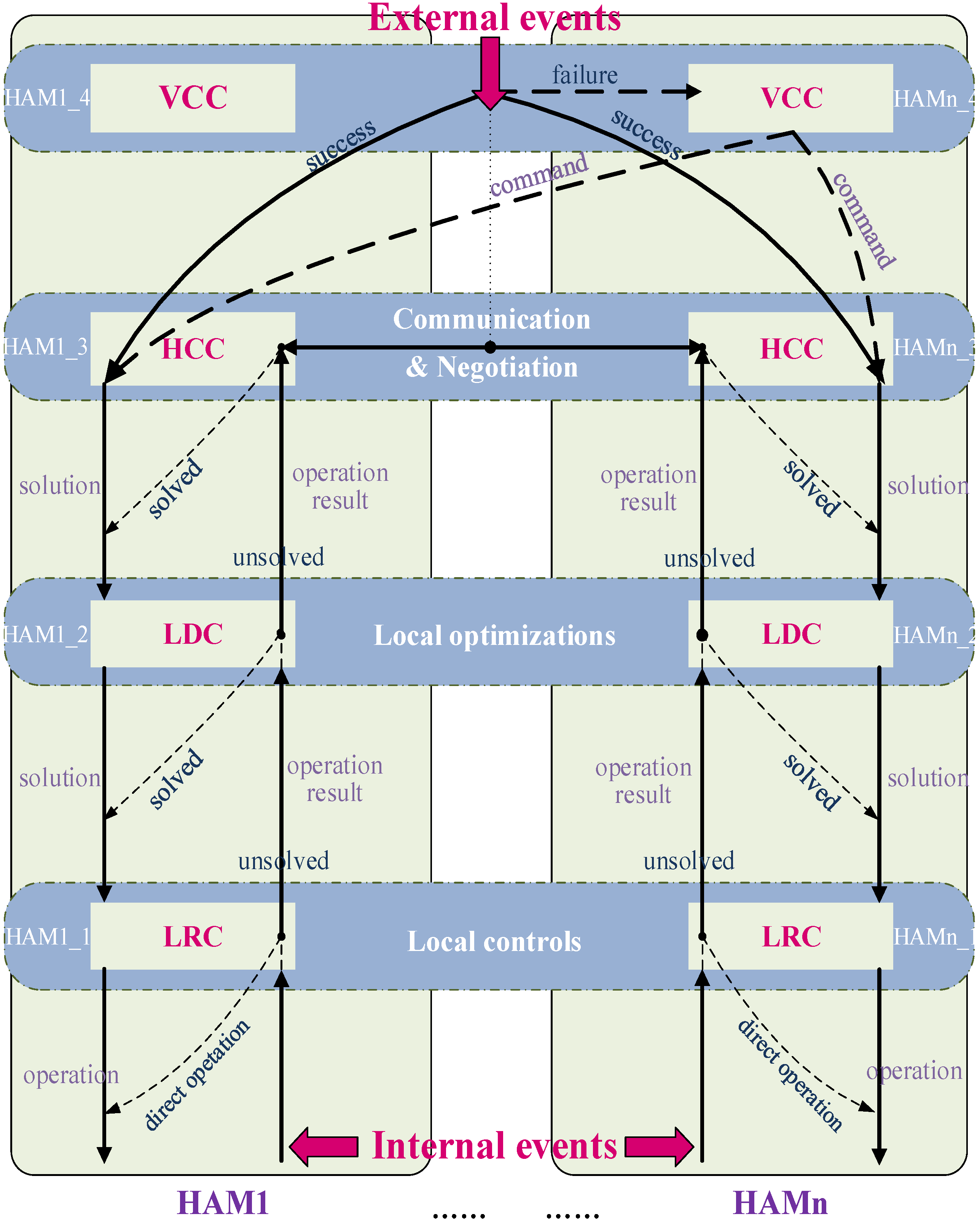
2.4. Operating Rules of Hybrid Multi-Agent Control Model
- (1)
- First, the operation events of microgrids are divided into two basic types: internal events and external events. Internal events include the state changes of microgrids and CUs (e.g., the changes of system operation mode, frequency, voltage, power, power quality, etc.), faults and other emergencies, which can be measured and detected by HAM itself (LRC level). External events include dispatching command, manual command, interaction information and so on, obtainable through external communication.
- (2)
- When HAM (e.g., HAM1) detects an internal event happening, the operation process will be:
- First, HAM1_1 works immediately and uploads the operation result directly to HAM1_2 whether the operation is successful or not. HAM1_2 either optimizes or corrects the result or directly uploads the result to HAM1_3 by determining whether HAM1 can independently deal with the event or not. Once HAM1_3 obtains the event from HAM1_2, it works and sends request to other HAMs, among which there are cooperation relations established beforehand.
- Next, a solution based on a certain optimization object for the event is deployed through several times of interactions among the HAMs. Meanwhile HAM1_3 uploads the solution to HAM1_4 whether the interaction is successful or not. Lastly, if HAM1_4 has the authority to control the other HAMs, a new operation plan with global optimization is made by HAM1_4, and sent to HAM1_1–HAMn_1 respectively.
- (3)
- When HAM (e.g., HAM2) detects an external event happening, the operation process is briefly described as follows: first, HAM1_2 determines whether the command is from HCC level (e.g., HAM1_3) or VCC level (e.g., HAM1_4). If the command is from HAM1_3, HAM2_3 starts to work and participates in the interactions initiated by HAM1. If the command is from HAM1_4, HAM2_1 starts to work and performs the command directly.

3. Implementations of Hybrid Multi-Agent Control Model Based on the IEC 61850 Standard
3.1. Analysis on Necessity and Feasibility
- (1)
- IEC 61850 is the global standard for power utility automation. Currently, most intelligent electronic devices (IEDs, such as protection, control and measurement unit) in power systems support IEC 61850. Hence, microgrids should adopt IEC 61850 in order to implement necessary interoperability with other IEDs and systems.
- (2)
- IEC 61850 combines the advantages of mainstream communication technologies (e.g., Ethernet) with the performance and security, enabling integration of protection, control, measurement and other functions. Hence, microgrids should adopt IEC 61850 due to its advances in communication and automation.
- (1)
- IEC 61850 is not merely a communication protocol, but also a modeling standard for automation. To be specific, IEC 61850 provides a series of data models and communication models as basic function entities to standardize various automation applications in power systems. Moreover, some concepts of MAS (e.g., intelligent agent unit, decentralized control, hierarchical control and so on) are consistent with some rules in IEC 61850 (e.g., abstract and free combination of automation applications, both vertical and horizontal function structure, and so on). Hence, it is convenient to develop HAM by using the data models and communication models defined in IEC 61850.
- (2)
- GOOSE is a communication model defined in IEC 61850, which provides the fast and reliable data transmissions among IEDs. GOOSE adopts some measures to ensure speed, convenience and reliability of data transmission, which are also the essence of HCF:
- GOOSE messages are directly mapped to Ethernet data packets for the sake of improving transmission efficiency and ensuring that the transmission time of each message is less than 4 ms. Hence, GOOSE is suitable for the time critical applications in microgrids and the current hardware and software conditions of practical devices due to its simple mapping rules.
- GOOSE adopts a publisher-subscriber mechanism in broadcast or multicast communication for the sake of conveniently transmitting data among different IEDs to implement different applications. Hence, it is convenient to implement multiple controls in different areas or under different time scales in HCF.
- GOOSE adopts the IEEE 802.1p priority tag for the sake of setting appropriate transmission priority levels for different operations. Hence, it is convenient to set priorities for different microgrid operations.
- GOOSE adopts enhanced retransmission mechanism with varying and increasing re-transmission intervals for the sake of improving transmission reliability as well as restricting network traffic.
3.2. Building a Data Model for Hybrid Multi-Agent Control Model Based on IEC 61850
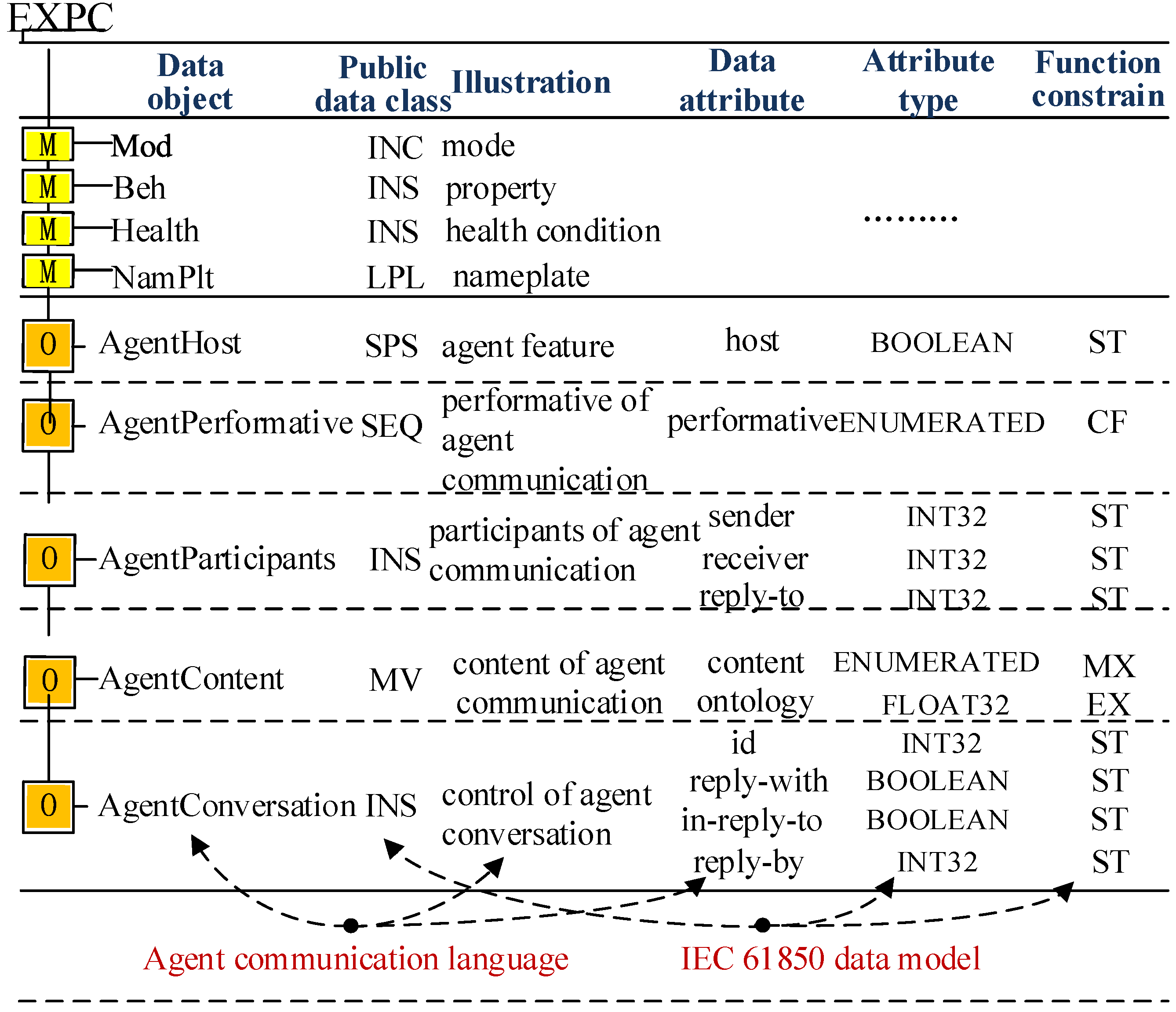
3.2.1. Logical Nodes of Hybrid Multi-Agent Control Model
- AgentHost is used to denote HAM1 working as HAM1_3 or HAM1_4. If AgentHost is equal to 0, it means HAM1 works as HAM1_3, namely the common agent in the HCC level. If AgentHost is equal to 1, it means HAM1 works as HAM1_4, namely the master agent in the VCC level.
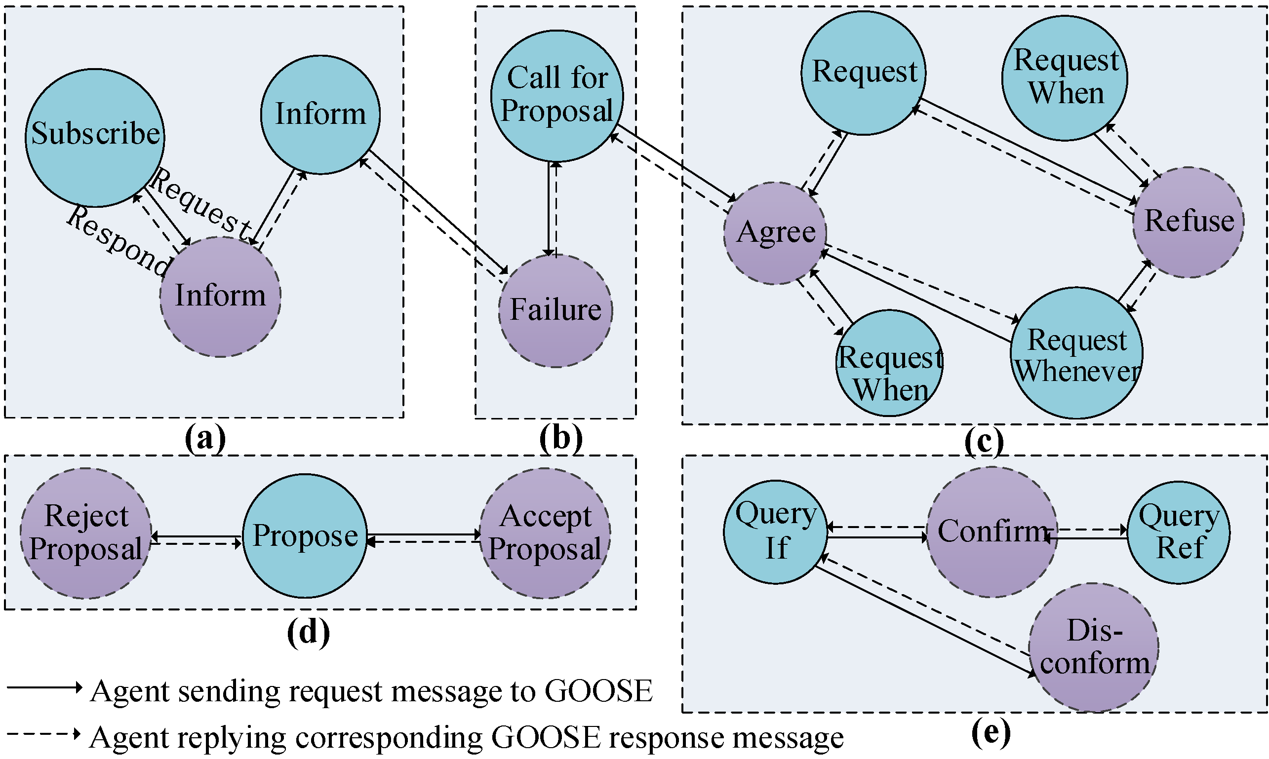
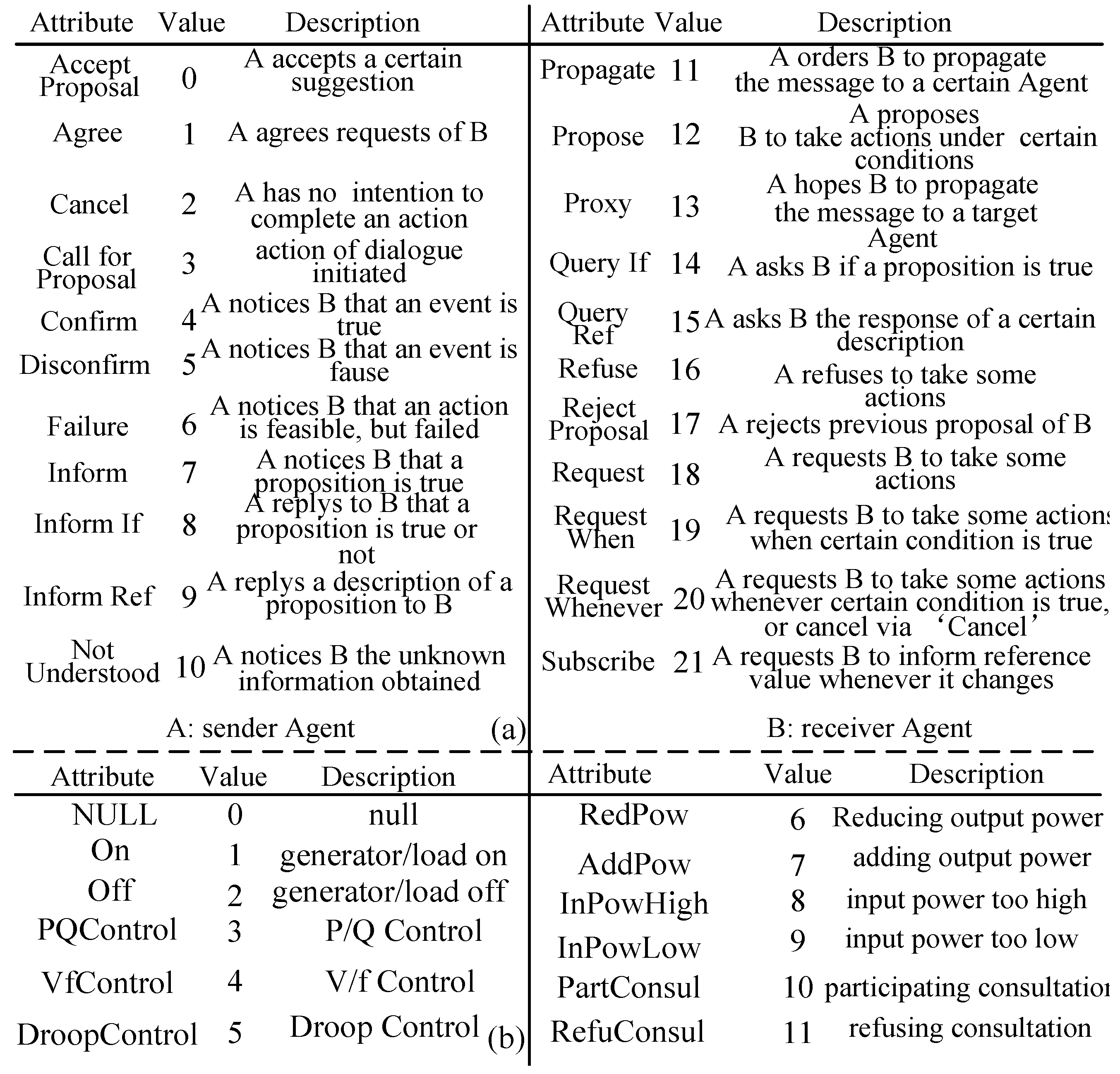
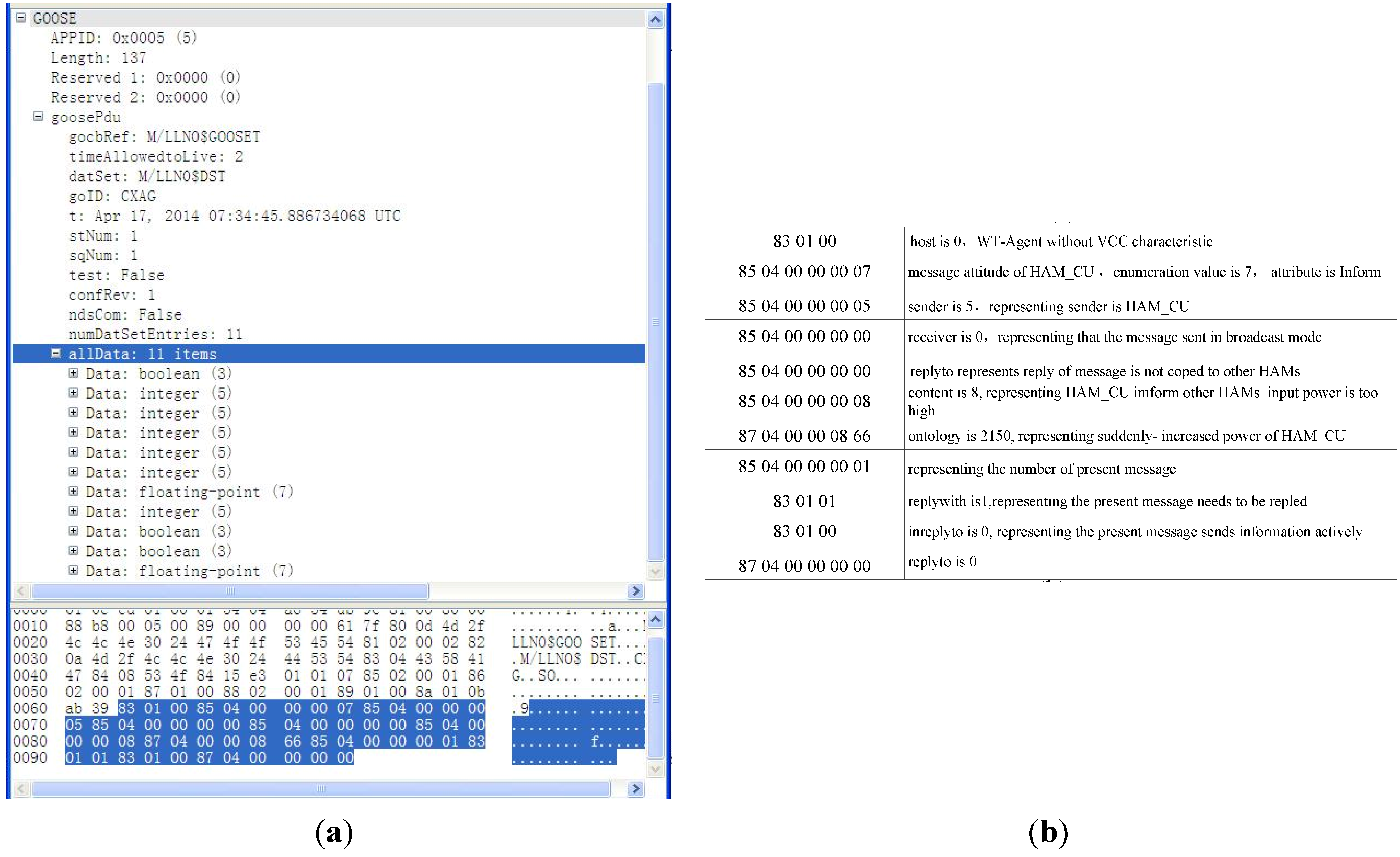
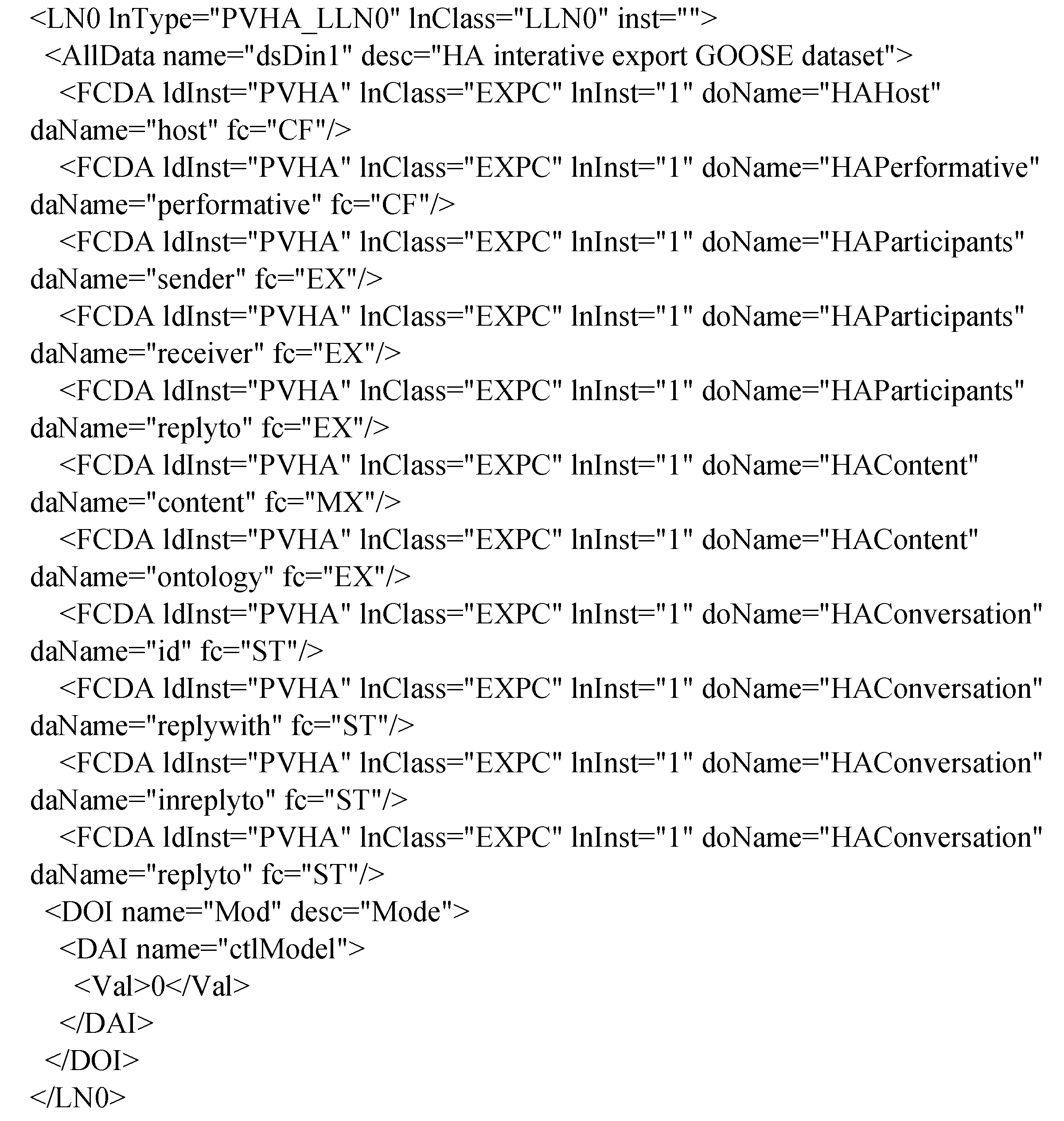
- AgentPerformative is used to define twenty-two types of actions and attitudes that might be adopted by agents during interaction as shown in Figure A1a in the Appendix.
- AgentContent is content of interaction, which includes two data attributes respectively contains some standardized control commands as shown in Figure A1b in the Appendix, and includes some supplementary specifications for content.
- AgentParticipants includes three parameters named sender, receiver and reply-to respectively, which are used to denote the sender, receiver and replier of specific interaction separately. AgentParticipants is useful for agents to understand interaction process.
- AgentConversation includes four parameters named id, reply-with, in-reply-to and reply-by, respectively. “id” is the unique identification of interaction. “reply-with” is used to describe whether message needs to be replied or not. The other two parameters are used to describe properties and time of message separately.

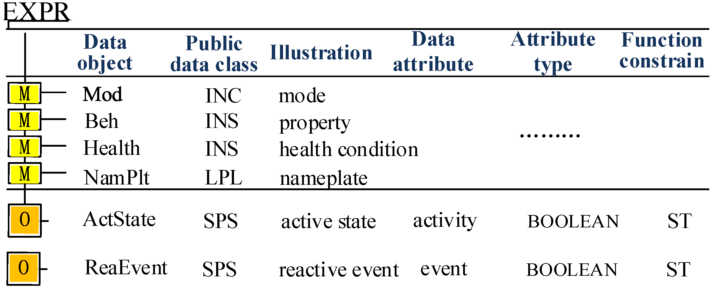
- ActState is used to denote working state of HAM1_1. If ActState is equal to 1, it means HAM1_1 is activated by internal or external operation event mentioned in Section 2.4. If ActState is equal to 0, it means HAM1_1 is not activated yet.
- ReaEvent is used to denote whether the operation event has been resolved by HAM1 or not. If ReaEvent is equal to 1, it means that HAM1 is capable of dealing with the event independently. If ReaEvent is equal to 0, it means that HAM1 demands help from other HAMs by activating HAM1_3 or HAM1_4.
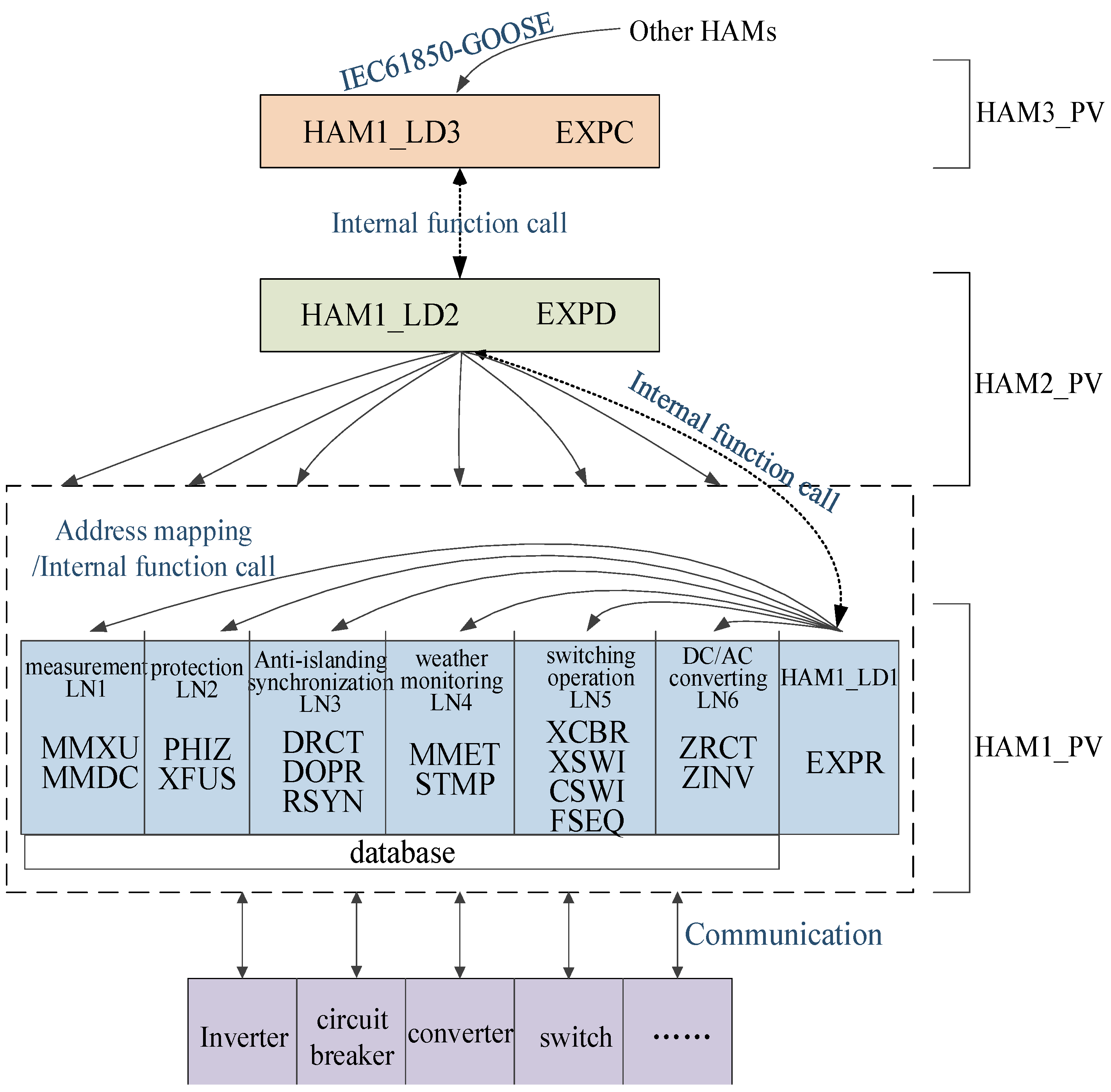
3.2.2. Logical Devices of Hybrid Multi-Agent Control Model

- HAM1_LD1 includes EXPR and other functional logical nodes (e.g., measurement, breaker operation and so on).
- Moreover, HAM1_LD2 includes EXPD, and HAM1_LD3 includes EXPC. As to the meaning of these functional logical nodes, please refer to the IEC 61850-7 Standard Document.
- Furthermore, EXPR exchanges information with other logical nodes in HAM1_LD1 through calling internal functions or address mapping. EXPD exchanges information with EXPR and EXPC by calling internal functions. EXPC exchanges information with other HAM through GOOSE communication.
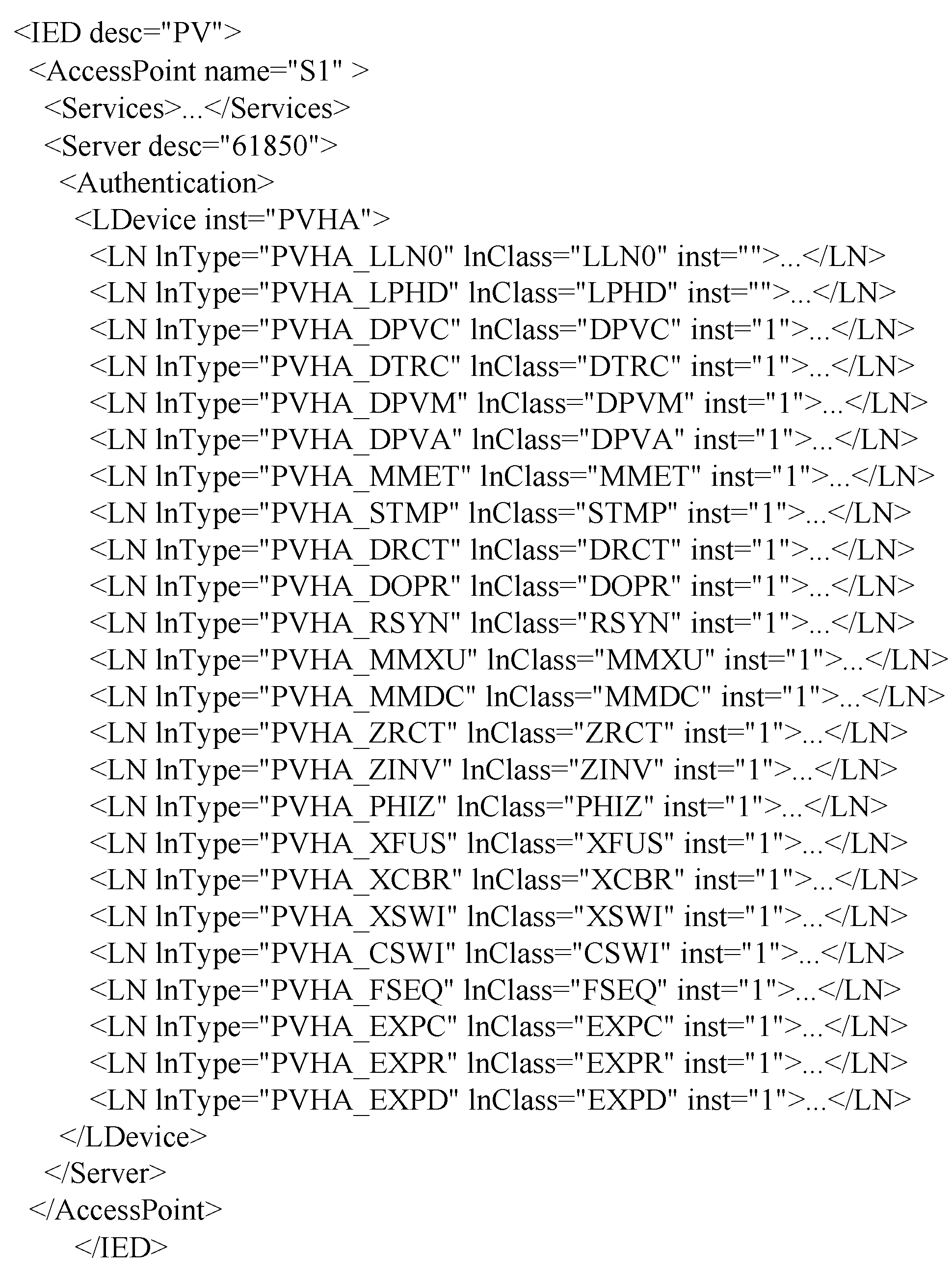
3.2.3. Representation of IEC 61850 Data Model
3.3. Building Communication Model for Hybrid Multi-Agent Control Model Based on IEC 61850
3.3.1. Bidirectional Interaction Mechanism of Generic Object Oriented Substation Event Communication
- If AgentPerformative is equal to twenty-one or seven, it means that the GOOSE message is a subscribed or informed message, and the receiver needs to reply with an informed message whose AgentPerformative is equal to seven, as shown in Figure 6a.
- If AgentPerformative is equal to three, it means the GOOSE message is a proposal message, and the receiver needs to reply with an agree or failure message whose AgentPerformative is equal to one or six, as shown in Figure 6b,c.
- Similarly, agree or refuse messages are used to reply with request, request when or request whenever messages, reject proposal or accept proposal messages are used to reply to propose messages, confirm messages are used to reply with query if or query ref message, and disconfirm messages are used to reply with query if messages, as shown in Figure 6b–e, respectively.
- Moreover, propagate and proxy messages do not need to be replied to in normal conditions. Only if the receiver fails to completely understand the received propagate or proxy message, will it reply with a not understood message. Then, the sender of the propagate or proxy message will additionally send inform if, inform ref or cancel messages to further explain the validity, details or cancellation of the former message, respectively.

3.3.2. Improvements on Transmitting, Capturing and Decoding Generic Object Oriented Substation Event Messages
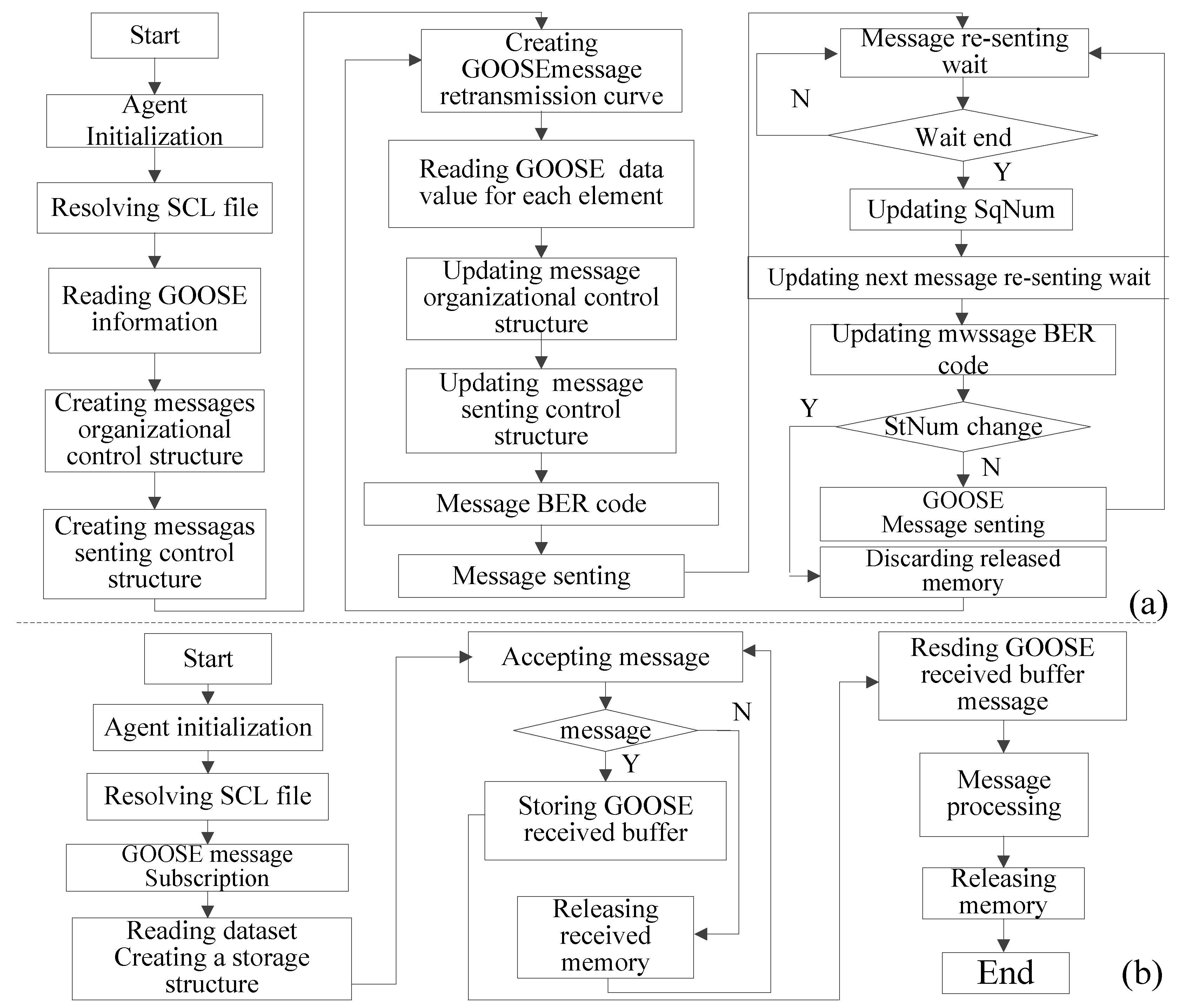
- Transmitting: some steps to transmit GOOSE messages are briefly shown in Figure A4a in the Appendix. Firstly, a data model of HAM including HAM_LDs, HAM_LNs and data objects is structured by parsing the substation configuration description language file organized beforehand. Secondly, a communication model of HAM is configured according to the GOOSE control block defined in the substation configuration description language file. Thirdly, the related dataset will be updated once the data value is changed due to an internal or external event. At last, a GOOSE message with the updated dataset is framed and transmitted under the rules of the data coding and communication mechanism defined in the GOOSE control block.
- Capturing: as stated in Section 3.1, a GOOSE message is directly mapped to an Ethernet data packet in order to reduce the time for framing, transmitting and decoding. Hence, it is necessary to bypass the surplus protocol stacks so that HAM could capture GOOSE messages from the data link layer directly. The procedures of capturing GOOSE message are briefly shown in Figure A4b in the Appendix.
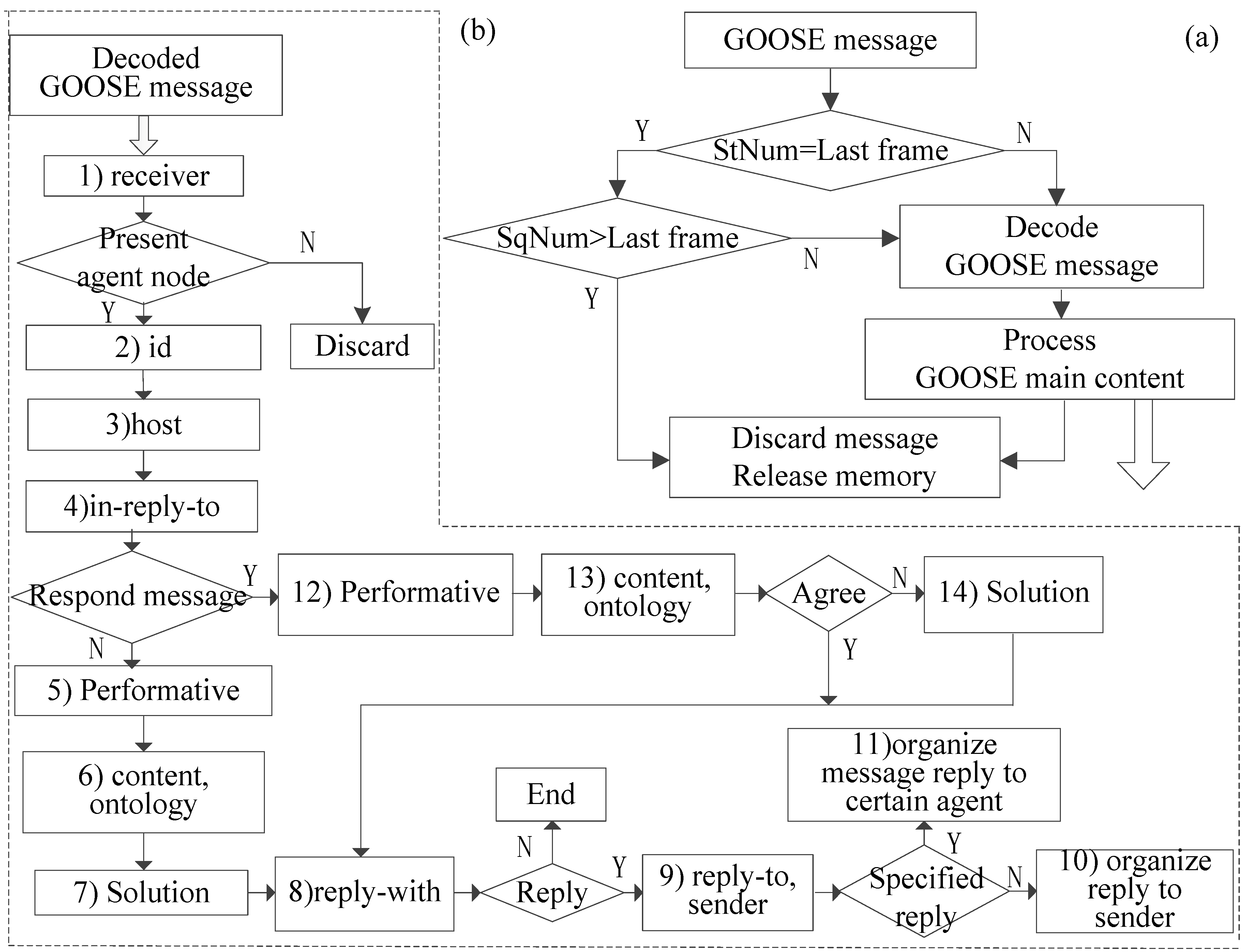
- Decoding: to reduce the time on decoding, it is not necessary to decode the whole GOOSE message except for some data segments, such as appID, StNum, SqNum and so on. For instance, StNum and SqNum need to be decoded to know whether the event in the captured message is a new operation or not, as shown in Figure A5a in the Appendix. Moreover, some judgments need to be done in turn as shown in Figure A5b in the Appendix. The details of the process are discussed below:
- ➢
- Firstly, the receiver re-checks if the message is targeted to itself according to the AgentParticipants data segment.
- ➢
- Then, the message sent from either a master agent (working on the VCC level) or a common agent (working on the HCC level) is judged according to the appID and AgentHost data segments.
- ➢
- As a result, if the message is from the VCC level, the receiver will directly execute the order and reply with the results.
- ➢
- Subsequently, some other data segments, such as AgentPerformative, AgentContent and so on, are decoded respectively and responded to with the communication mechanism proposed above.
4. Simulation and Laboratory Tests
4.1. Simulation Study

4.2. Laboratory Test
4.2.1. Introduction to the Test System
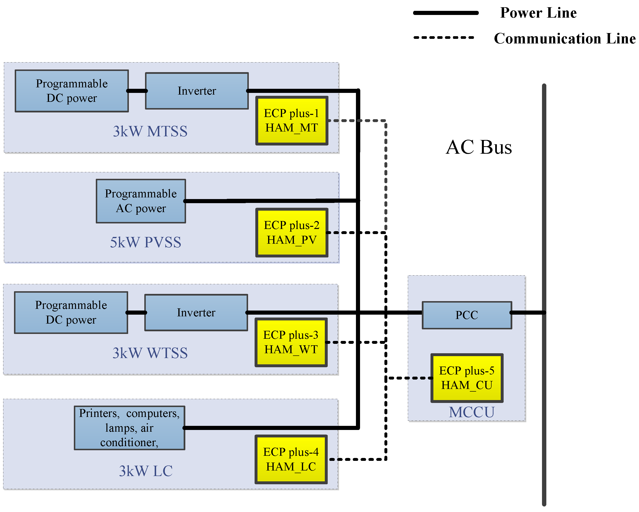
- Construction of the test system: the test system is a three-phases 380 V/50 Hz ac power bus connected with a wind turbine generation simulation system (WTSS), a photovoltaic generation simulation system (PVSS), a micro-turbine generation simulation system (MTSS), a measurement and control unit (MCCU) installed at the PCC and some actual loads (e.g., computers, printers, lamps, air conditioner, and so on) with LC. WTSS and MTSS respectively consist of a programmable dc power source (Chroma 62150H-600S) and a 3 kW general controllable current source inverter (SMA Windyboy3000). PVSS is simulated by a programmable ac power source (Chroma 61511).
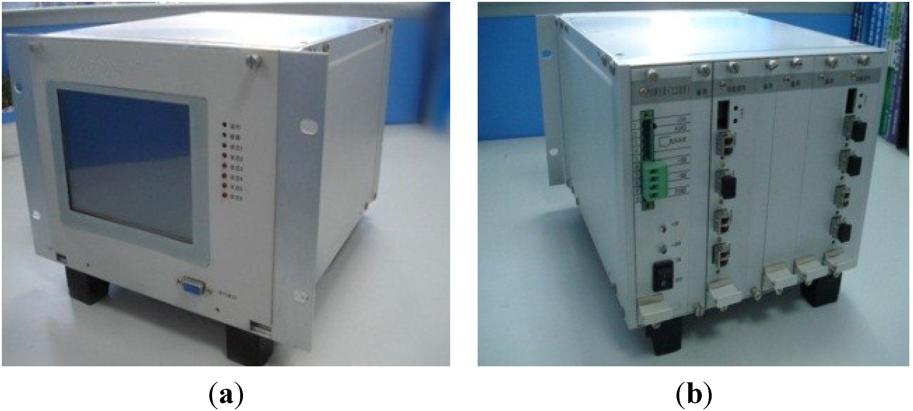
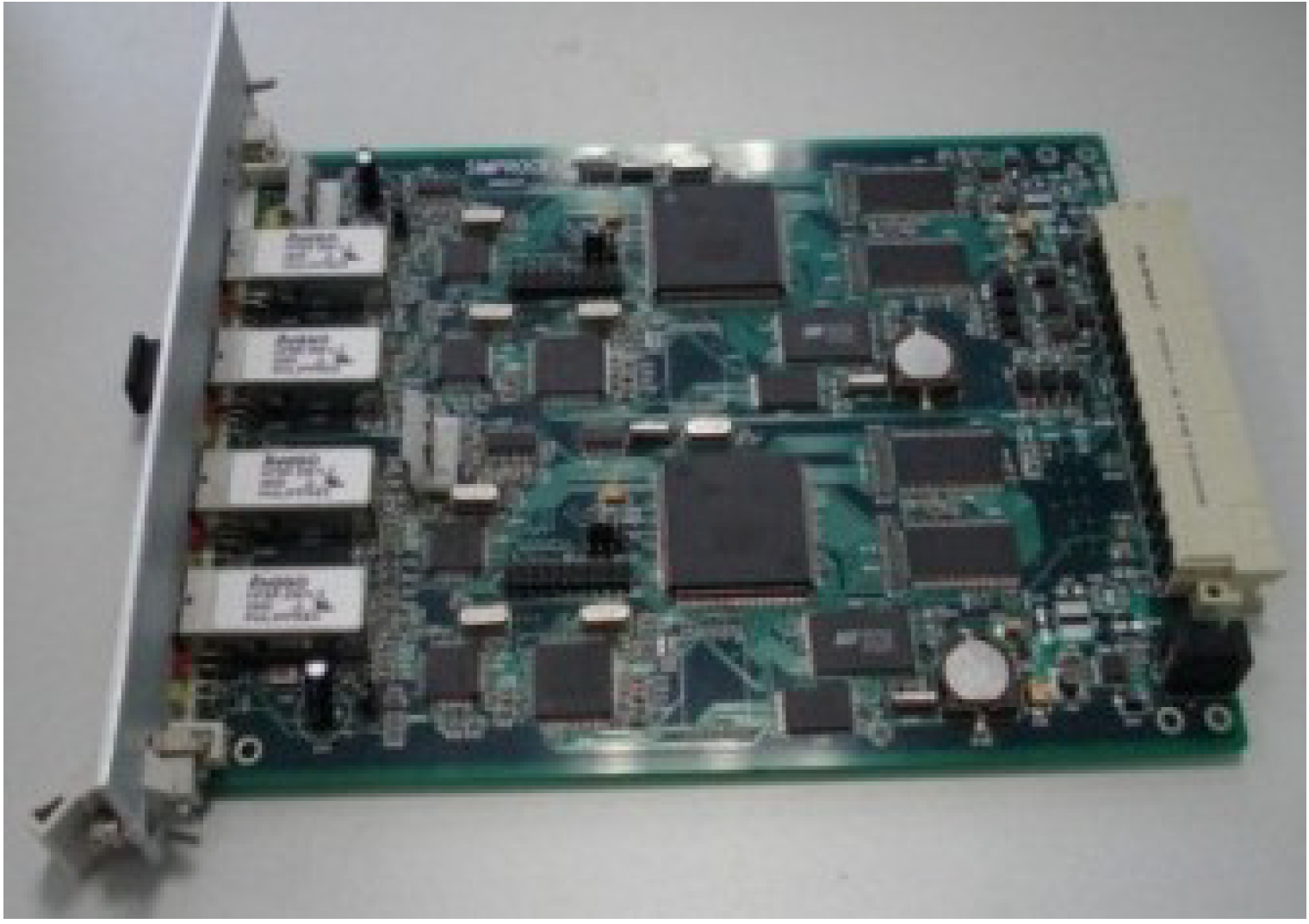
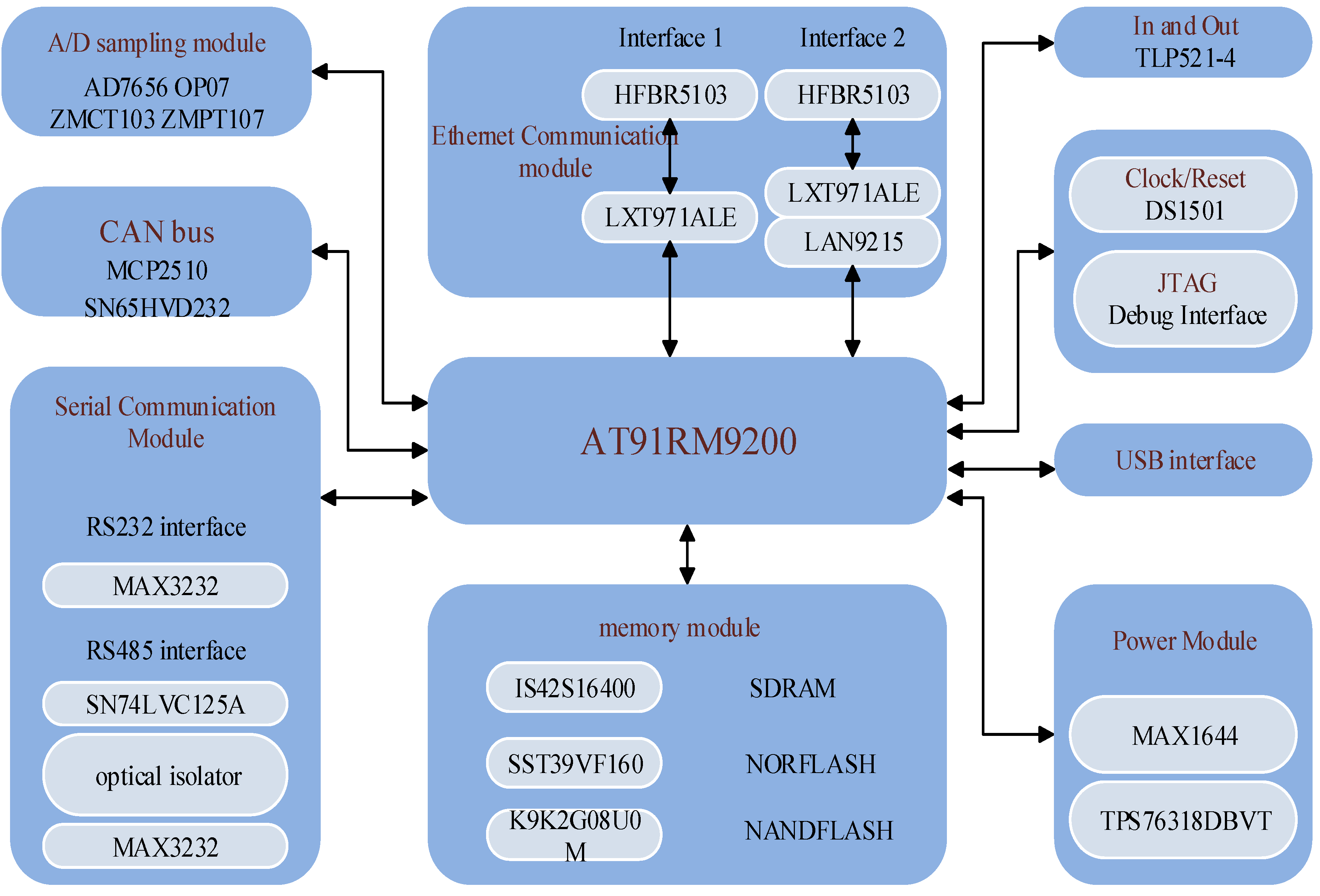
- Development of HAM: based on the hardware design shown in Figure A6 in the Appendix, some devices named ECP plus are developed, instead of using common computers to implement the functions of the proposed HAM, specifically the controls in the HCC and VCC levels with GOOSE communication. The ECP plus hardware platform is based on an Atmel AT91RM9200 microcontrol unit, and the software platform is a VxWorks embedded operation system, and standard C programming language is used for software development. In the laboratory tests, each ECP plus (HAM) belongs to a specific CU as shown in Figure 8, and all the HAMs are connected together via 100Mbps fiber Ethernet. Photographs of the ECP plus and its main control board are respectively shown in Figure A7 and Figure A8 in the Appendix.
4.2.2. Test of Controls in Local Reaction Control and Local Decision Control Levels
| Scenario | Time | Control Function | Description |
|---|---|---|---|
| I | 0–21 s | MPPT mode | WTSS increases generation while wind speed increases, and stays rated while the speed exceeds rated but below maximum limitation. |
| >21 s | Generation limitation mode | ||
| II | 0–21 s | MPPT mode | WTSS autonomously cuts off while wind speed exceeds maximum limitation. |
| 21–32 s | Generation limitation mode | ||
| >32 s | Cut off WTSS | ||
| III | 0–40 s | MPPT mode | WTSS intelligently adopts MPPT control strategy while wind speed is fluctuating. |
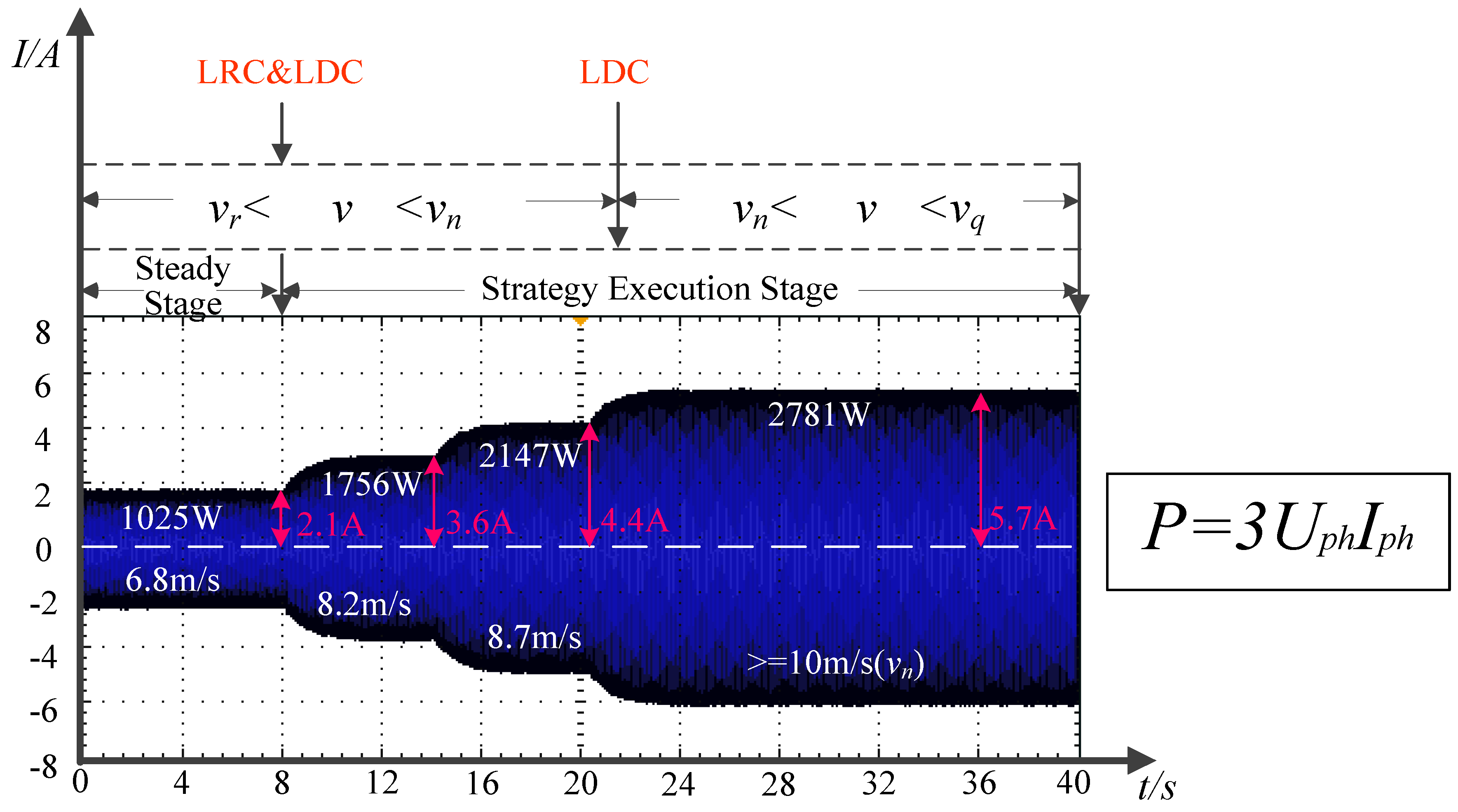
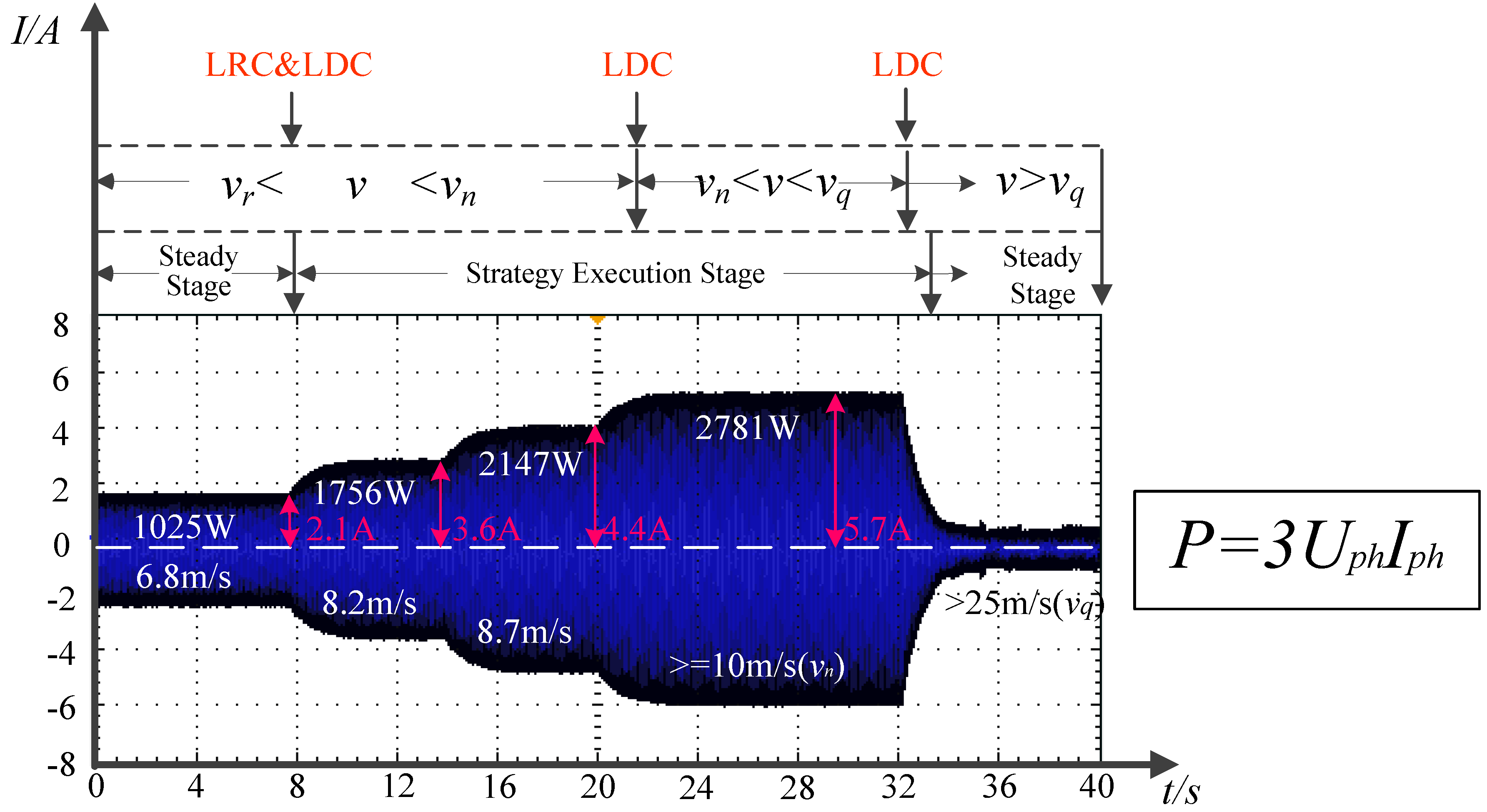
- Scenario I: Scenario I presents a local control of HAM_WT where WTSS increases generation following the growth of wind speed (v) and stays rated while the wind speed exceeds the rated value (vn = 10m/s) but stays below the maximum limitation (vq = 25 m/s) as shown in Figure 9. During the process, the LRC level of HAM_WT continuously measures the generation of WTSS and updates it to the LDC level for further optimization, such as MPPT control and generation limitation and so on, once a change of wind speed is detected (at 8 s and 21 s).

- Scenario II: Scenario II presents WTSS cuts off generation when the wind speed exceeds the maximum speed limitation as shown in Figure 10. From 0 s to 32 s, the situation is the same as Scenario I. After 32 s, HAM_WT detects that the wind speed has exceeded the maximum speed so that LDC level instructs the LRC level to cut off WTSS, presenting a sudden decrease of generation in Figure 10.
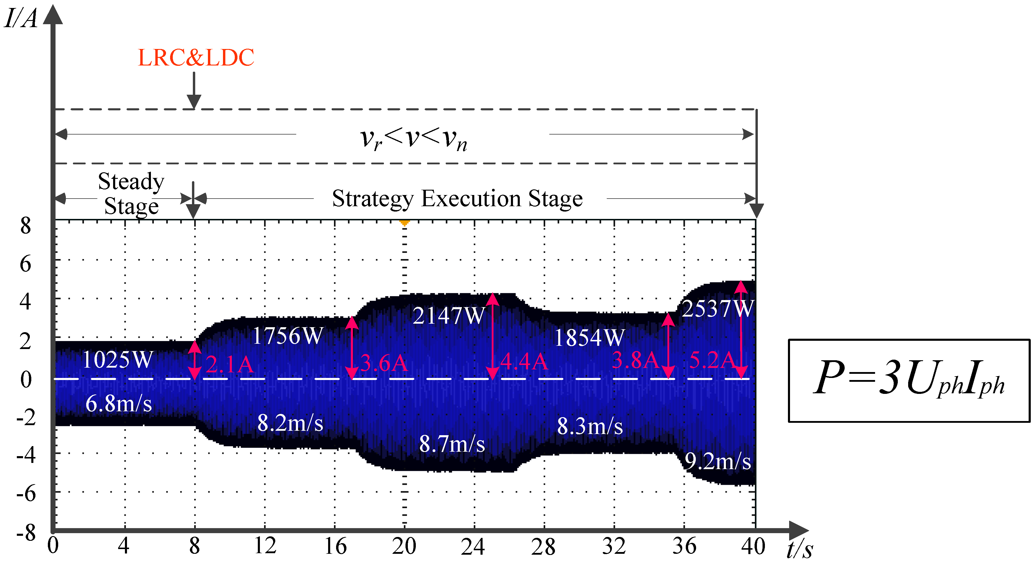
- Scenario III: Scenario III presents that WTSS adopts a MPPT control strategy when the wind speed fluctuates in a certain range (vr < v < vn, vr = 3 m/s) as shown in Figure 11.

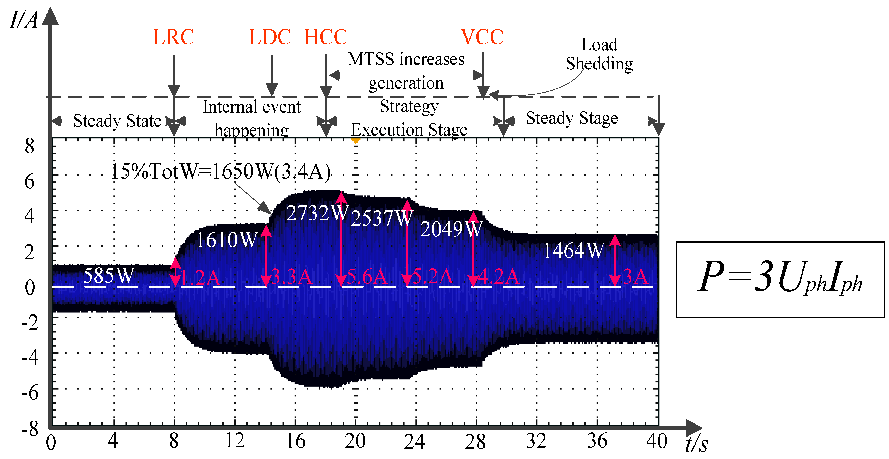
4.2.3. Test of Controls in Horizontal Cooperation Control and Vertical Cooperation Control Levels
| Time | Control level | Control function |
|---|---|---|
| 8–15 s | LRC | The input of WTSS&PVSS is regulated to zero. |
| 15 s | LDC | Internal event (excess of CUHA.MMXU.TotW) is detected. |
| 15–17 s | LDC | Continuous detecting of the excess. |
| 17 s | HCC | HCC of HAM_CU starts negotiation. |
| 18–28 s | HCC and LDC | MTSS performs a two-stage decrease of CUHA.MMXU.TotW. |
| 28 s | VCC | VCC of HAM_CU commands load shedding. |
| 28–30 s | LDC | LC performs load shedding. |
| >30 s | HCC | CUHA.MMXU.TotW is less than 1.65 kW. The coordinated control is finished. |
- From 8 s to 15 s, the inputs of WTSS and PVSS are gradually regulated to zero to simulate the intermittent nature of renewable energies. At 15 s, the LRC level of HAM_CU measures the active power absorbed from the connected grid (CUHA.MMXU.TotW) having exceeded 15% of the total rated generation of test system (TotW), which is made up as below:PVHA.ZINV.OutWSet, WTHA.ZINV.OutWSet and MTHA.ZINV.OutWSet are the rated output power of PVSS, WTSS and MTSS, respectively. 15% of TotW is 1.65 kW. After 2 s of continuous detection, the LDC level confirms the excess and informs the HCC level of HAM_CU.
- At 17 s, since HAM_CU has no ability to control the power flow independently, it broadcasts an inform message to other HAMs. The inform message organized as a GOOSE message is shown in Figure A9 in the Appendix. The HCC levels of HAM_PV, HAM_WT, HAM_MT and HAM_LC obtain the coordinated control invitation from the received inform message, and deliver it to the LDC levels.
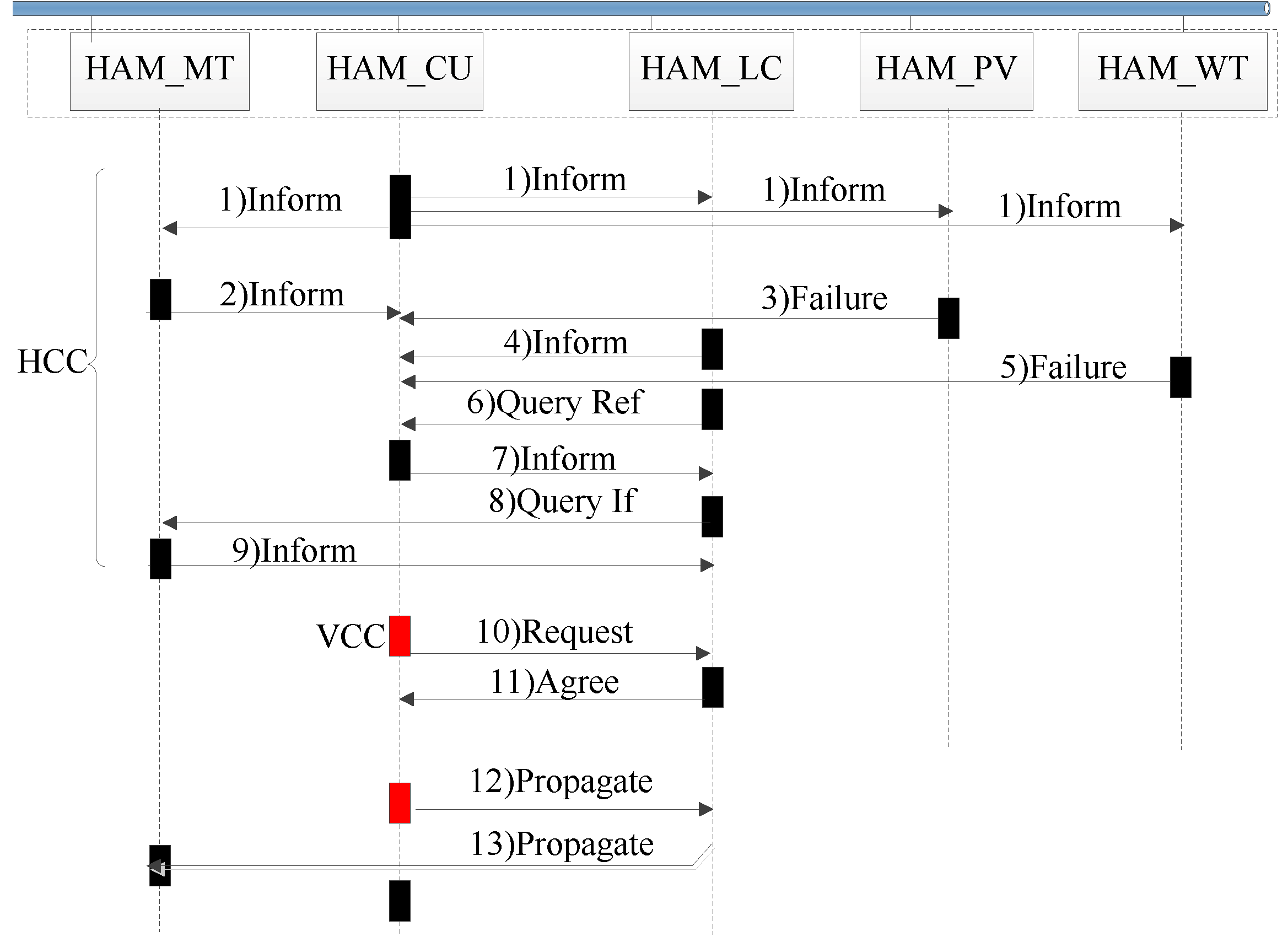
- From 18 s to 28 s, HAM_LC and HAM_MT implement the negotiation stated above twice, and then HAM_MT increases its output power twice resulting in a two-stage decrease of CUHA.MMXU.TotW that can be observed in Figure 13, and a detailed process is presented in Table 3. During the process, the LRC level of HAM_CU continuously measures CUHA.MMXU.TotW.
- At 28 s, HAM_CU measures that CUHA.MMXU.TotW is still more than 1.65 kW. Hence, a request message is transmitted from HAM_CU to HAM_LC commanding LC to perform load shedding directly. Then, HAM_LC replies with a confirm message and acts according to the setting values in the command message. As a result, CUHA.MMXU.TotW decreases rapidly as shown in Figure 13.
- After 30 s, CUHA.MMXU.TotW is less than 1.65 kW, a propagate message is transmitted from HAM_CU to HAM_LC to inform LC that the power flow control has finished and load shedding need not be implemented. Subsequently, a propagate message is transmitted from HAM_LC to HAM_MT to inform MTSS that the coordinated control is finished and the output should remain constant.

| Level | Times | Description |
|---|---|---|
| LRC | 1 | Measurement on the active power absorbed from the connected grid implemented by HAM_CU. |
| LDC | 4 |
|
| HCC | 5 |
|
| VCC | 1 | HAM_CU requests HAM_LC to implement load shedding. |
4.2.4. Analysis on Generic Object Oriented Substation Event Communication Delay
- Scenario IV was tested five times. The coordinated control was successful every time, and the delay including computing time, transmission delay of GOOSE message and control execution time was always less than 1 s, as can be seen in Figure 13.
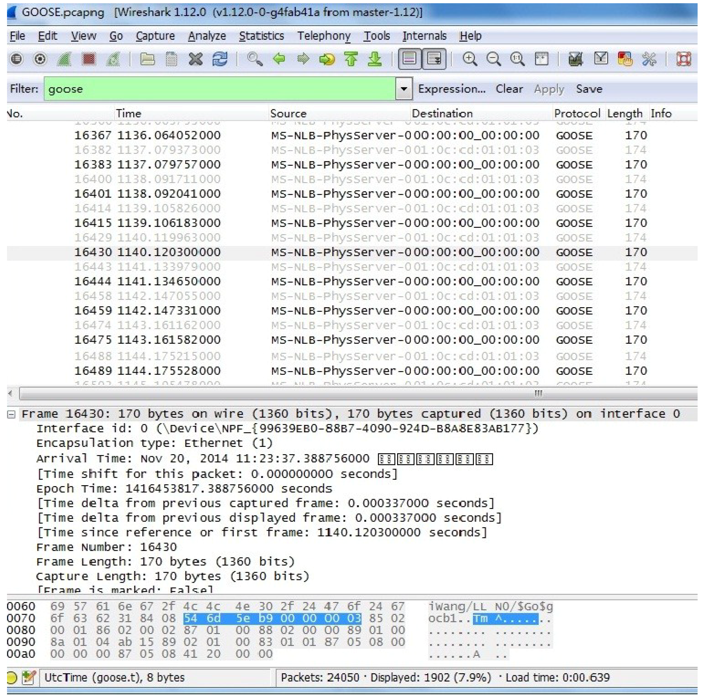
- In order to analyze the communication delay in Scenario IV more specifically, the negotiation between HAM_LC and HAM_MT based on GOOSE messages mentioned above was tested several times. The value of the communication delay obtained with Wireshark (a kind of package capturing tool) shows that it takes approximately 1 ms from HAM_LC sending a query ref message to HAM_LC receiving an inform message from HAM_MT as can be seen from Figure A10 in the Appendix, which illustrates that GOOSE messages are suitable for the time critical controls in a microgrid.
- The realization of control in HAM_3 and HAM_4 in different scenaerios such as Scenario IV is essentially based on an open-loop control instead of real-time feedback control. It means that the delay can only have an influence on the time of corresponding controls’ achievement but not the stability of the system.
5. Conclusions and Future Work
Acknowledgments
Author Contributions
Acronyms
| DG | Distributed generator |
| DS | Distributed storage |
| MAS | Multi-agent system |
| CU | Control unit |
| LC | Load controller |
| JADE | Java agent development framework |
| HCF | Hierarchical control framework |
| HAM | Hybrid multi-agent model |
| GOOSE | Generic object oriented substation event |
| LRC | Local reaction control |
| LDC | Local decision control |
| HCC | Horizontal cooperation control |
| VCC | Vertical cooperation control |
| MGCC | Microgrid control center |
| PCC | Point of common coupling |
| MT | Micro-turbine |
| MPPT | Maximum power point tracking |
| IEDs | Intelligent electronic devices |
| HAM_LNs | Extended logical nodes for HAM |
| EXPC | Logical node extended for HCC and VCC controls in HAM |
| EXPD | Logical node extended for LDC controls in HAM |
| EXPR | Logical node extended for LRC controls in HAM |
| HAM_LDs | Extended logical devices for HAM |
| WTSS | Wind turbine generation simulation system |
| PVSS | Photovoltaic generation simulation system |
| MTSS | Micro-turbine generation simulation system |
| MCCU | Measurement and control unit |
| ECP plus | Device designed for implementing the functions of HAM |
| HAM_MT | HAM of MTSS |
| HAM_PV | HAM of PVSS |
| HAM_WT | HAM of WTSS |
| HAM_CU | HAM of MCCU |
| HAM_LC | HAM of LC |
| CUHA.MMXU.TotW | The active power absorbed from the connected grid |
| PVHA | Logical device of HAM_PV |
| WTHA | Logical device of HAM_WT |
| MTHA | Logical device of HAM_MT |
- (1)
- AgentHost, AgentPerformative, AgentContent, AgentParticipants, AgentConversation, ActState and ReaEvent are the data objects of HAM_LNs.
- (2)
- sender, receiver and reply-to are the parameters of AgentParticipants.
- (3)
- id, reply-with, in-reply-to and reply-by are the parameters of AgentConversation.
- (4)
- appID, StNum, SqNum are the specific data segments in GOOSE message.
Appendix


Conflicts of Interest
References
- Khodayar, M.E.; Barati, M.; Shahidehpour, M. Integration of high reliability distribution system in microgrid operation. IEEE Trans. Smart Grid 2012, 3, 1997–2006. [Google Scholar] [CrossRef]
- Lu, Z.; Wang, C.; Min, Y.; Zhou, S.; Lv, J.; Wang, Y. Overview on microgrid research. (in Chinese). Autom. Electr. Power Syst. 2007, 31, 100–107. [Google Scholar]
- Tan, K.T.; So, P.L.; Chu, Y.C.; Chen, M.Z.Q. Coordinated control and energy management of distributed generation inverters in a microgrid. IEEE Trans. Power Deliv. 2013, 28, 704–713. [Google Scholar] [CrossRef] [Green Version]
- Chung, I.Y.; Liu, W.; Cartes, D.A.; Collins, E.G.; Moon, S.I. Control methods of inverter-interfaced distributed generators in a microgrid system. IEEE Trans. Ind. Appl. 2010, 46, 1078–1088. [Google Scholar] [CrossRef]
- Katiraei, F.; Iravani, R.; Hatziargyriou, N.; Dimeas, A. Microgrids management. IEEE Power Energy Mag. 2008, 6, 54–65. [Google Scholar] [CrossRef]
- Liu, X.; Wang, P.; Loh, P.C. A hybrid AC/DC microgrid and its coordinated control. IEEE Trans. Smart Grid 2011, 2, 278–286. [Google Scholar] [CrossRef]
- Gao, F.; Iravani, M.R. A control strategy for a distributed generation unit in grid-connected and autonomous modes of operation. IEEE Trans. Power Deliv. 2008, 23, 850–859. [Google Scholar] [CrossRef]
- Pogaku, N.; Prodanovic, M.; Green, T.C. Modeling, analysis and testing of autonomous operation of an inverter-based microgrid. IEEE Trans. Power Electron. 2007, 22, 613–625. [Google Scholar] [CrossRef]
- Guerrero, J.M.; Hang, L.; Uceda, J. Control of distributed uninterruptible power supply systems. IEEE Trans. Ind. Electron. 2008, 55, 2845–2859. [Google Scholar] [CrossRef] [Green Version]
- Tsikalakis, A.G.; Hatziargyriou, N.D. Centralized control for optimizing microgrids operation. IEEE Trans. Energy Convers. 2008, 23, 241–248. [Google Scholar] [CrossRef]
- Piagi, P.; Lasseter, R.H. Autonomous control of microgrids. In Proceedings of the 2006 IEEE Power Engineering Society General Meeting, Montreal, QC, Canada, 18–22 June 2006.
- Tan, K.T.; Peng, X.Y.; So, P.L.; Chu, Y.C.; Chen, M.Z.Q. Centralized control for parallel operation of distributed generation inverters in microgrids. IEEE Trans. Smart Grid 2012, 3, 1977–1987. [Google Scholar] [CrossRef] [Green Version]
- Dou, C.X.; Liu, B. Multi-agent based hierarchical hybrid control for smart microgrid. IEEE Trans. Smart Grid 2013, 4, 771–778. [Google Scholar] [CrossRef]
- Ilic, M.D.; Liu, S.X. Hierarchical power systems control: Its value in a changing industry. In Advances in Industrial Control; Springer: London, UK, 1996. [Google Scholar]
- Ilic-Spong, M.; Christensen, J.; Eichorn, K.L. Secondary voltage control using pilot point information. IEEE Trans. Power Syst. 1988, 3, 660–668. [Google Scholar] [CrossRef]
- McArthur, S.D.J.; Davidson, E.M.; Catterson, V.M.; Dimeas, A.L.; Hartziargyriou, N.D.; Ponci, F.; Funabashi, T. Multi-agent systems for power engineering applications—Part I: Concepts, approaches, and technical challenges. IEEE Trans. Power Syst. 2007, 22, 1743–1752. [Google Scholar] [CrossRef] [Green Version]
- McArthur, S.D.J.; Davidson, E.M.; Catterson, V.M.; Dimeas, A.L.; Hartziargyriou, N.D.; Ponci, F.; Funabashi, T. Multi-agent systems for power engineering applications—Part II: Technologies, standards, and tools for building multi-agent systems. IEEE Trans. Power Syst. 2007, 22, 1753–1759. [Google Scholar] [CrossRef] [Green Version]
- Zhang, J.; Ai, Q.; Wang, X. Application of multi-agent system in a microgrid. (in Chinese). Autom. Electr. Power Syst. 2008, 32, 80–82. [Google Scholar]
- Wu, Z.; Gu, W. Active power and frequency control of islanded microgrid based on multi-agent technology. Electr. Power Autom. Equip. 2009, 29, 57–61. (In Chinese) [Google Scholar]
- Xu, Y.; Liu, W. Novel multiagent based load restoration algorithm for microgrids. IEEE Trans. Smart Grid 2011, 2, 152–161. [Google Scholar] [CrossRef]
- Hao, Y.; Wu, Z.; Dou, X.; Hu, M.; Zhao, B. Application of multi-agent systems to the DC microgrid stability control. (in Chinese). Proc. CSEE 2012, 32, 27–35. [Google Scholar]
- Logenthiran, T.; Srinivasan, D.; Khambadkone, A.M.; Aung, H.N. Multi-Agent System (MAS) for short-term generation scheduling of a microgrid. In Proceedings of the 2010 IEEE International Conference on Sustainable Energy Technology (ICSET), Kandy, Sri Lanka, 6–9 December 2010; pp. 1–6.
- Kuo, M.T.; Lu, S.D. Design and implementation of real-time intelligent control and structure based on multi-agent systems in microgrids. Energies 2013, 6, 6045–6059. [Google Scholar] [CrossRef]
- Communication Networks and Systems in Substations—All Parts; IEC 61850 Ed 2.0; International Electrotechnical Commission (IEC): Geneva, Switzerland, 2009.
- Münz, U.; Papachristodoulou, A.; Allgöwer, F. Delay robustness in consensus problems. Automatica 2010, 46, 1252–1265. [Google Scholar] [CrossRef]
- Solanki, J.M.; Khushalani, S.; Schulz, N.N. A multi-agent solution to distribution systems restoration. IEEE Trans. Power Syst. 2007, 22, 1026–1034. [Google Scholar] [CrossRef]
- Higgins, N.; Vyatkin, V.; Nair, N.C.; Schwarz, K. Distributed power system automation with IEC 61850, IEC 61499, and intelligent control. IEEE Trans. Syst. Man Cybern. Part C Appl. Rev. 2011, 41, 81–92. [Google Scholar] [CrossRef]
- Sidhu, T.S.; Yin, Y. Modelling and simulation for performance evaluation of IEC61850-based substation communication systems. IEEE Trans. Power Deliv. 2007, 22, 1482–1489. [Google Scholar] [CrossRef]
- Communication Networks and Systems for Power Utility Automation—Part 7-420: Basic Communication Structure—Distributed Energy Resources Logical Nodes; IEC Std. 61850 Ed 1.0; International Electrotechnical Commission (IEC): Geneva, Switzerland, 2009.
- Ustun, T.; Ozansoy, C.; Zayegh, A. Modeling of a centralized microgrid protection system and distributed energy resources according to IEC 61850-7-420. IEEE Trans. Power Syst. 2012, 27, 1560–1567. [Google Scholar] [CrossRef]
- Ruiz-Alvarez, A.; Colet-Subirachs, A.; Alvarez-Cuevas Figuerola, F.; Gomis-Bellmunt, O.; Sudria-Andreu, A. Operation of a utility connected microgrid using an IEC 61850-based multi-level management system. IEEE Trans. Smart Grid 2012, 3, 858–865. [Google Scholar] [CrossRef]
- Colet-Subirachs, A.; Ruiz-Alvarez, A.; Gomis-Bellmunt, O.; Alvarez-Cuevas-Figuerola, F.; Sudria-Andreu, A. Centralized and distributed active and reactive power control of a utility connected microgrid using IEC 61850. IEEE Syst. J. 2012, 6, 58–67. [Google Scholar] [CrossRef]
© 2014 by the authors; licensee MDPI, Basel, Switzerland. This article is an open access article distributed under the terms and conditions of the Creative Commons Attribution license (http://creativecommons.org/licenses/by/4.0/).
Share and Cite
Dou, X.; Quan, X.; Wu, Z.; Hu, M.; Yang, K.; Yuan, J.; Wang, M. Hybrid Multi-Agent Control in Microgrids: Framework, Models and Implementations Based on IEC 61850. Energies 2015, 8, 31-58. https://doi.org/10.3390/en8010031
Dou X, Quan X, Wu Z, Hu M, Yang K, Yuan J, Wang M. Hybrid Multi-Agent Control in Microgrids: Framework, Models and Implementations Based on IEC 61850. Energies. 2015; 8(1):31-58. https://doi.org/10.3390/en8010031
Chicago/Turabian StyleDou, Xiaobo, Xiangjun Quan, Zaijun Wu, Minqiang Hu, Kang Yang, Jian Yuan, and Mengmeng Wang. 2015. "Hybrid Multi-Agent Control in Microgrids: Framework, Models and Implementations Based on IEC 61850" Energies 8, no. 1: 31-58. https://doi.org/10.3390/en8010031