Article

Effects of Pretreatment Methods on Electrodes and SOFC Performance

1
Department of Mechanical Engineering & Fuel Cell Center, Yuan Ze University, Taoyuan 32003, Taiwan
2
Taiwan Power Company, New Taipei City 23847, Taiwan
*
Author to whom correspondence should be addressed.
Energies 2014, 7(6), 3922-3933; https://doi.org/10.3390/en7063922
Submission received: 29 April 2014 / Revised: 1 June 2014 / Accepted: 17 June 2014 / Published: 23 June 2014
(This article belongs to the Special Issue Reacting Transport Phenomena in Solid Oxide Fuel Cells)

Abstract

:
Commercially available tapes (anode, electrolyte) and paste (cathode) were choosen to prepare anode-supported cells for solid oxide fuel cell applications. For both anode-supported cells or electrolyte-supported cells, the anode needs pretreatment to reduce NiO/YSZ to Ni/YSZ to increase its conductivity as well as its catalytic characteristics. In this study, the effects of different pretreatments (open-circuit, closed-circuit) on cathode and anodes as well as SOFC performance are investigated. To investigate the influence of closed-circuit pretreatment on the NiO/YSZ anode alone, a Pt cathode is utilized as reference for comparison with the LSM cathode. The characterization of the electrical resistance, AC impedance, and SOFC performance of the resulting electrodes and/or anode-supported cell were carried out. It’s found that the influence of open-circuit pretreatment on the LSM cathode is limited. However, the influence of closed-circuit pretreatment on both the LSM cathode and NiO/YSZ anode and the resulting SOFC performance is profound. The effect of closed-circuit pretreatment on the NiO/YSZ anode is attributed to its change of electronic/pore structure as well as catalytic characteristics. With closed-circuit pretreatment, the SOFC performance improved greatly from the change of LSM cathode (and Pt reference) compared to the Ni/YSZ anode.

1. Introduction

Fuel cell technology has attracted wide attention globally due to its high electrochemical efficiency and low emissions. Compared to the low temperature proton exchange membrane fuel cell (PEMFC) with its high Pt catalyst cost, easy catalyst poisoning, water and heat management problems andneed for extra auxiliary reforming, the high temperature solid oxide fuel cell (SOFC) has been studied more [1,2] due to its higher conversion efficiency, no need for Pt catalyst, and simpler system overall [3]. Solid proof of this difference could be garnered from the electronic journal system Science Direct. Using as the input keywords “solid oxide fuel cell”, and considering just the time period from 2001 to 2011, the total number of papers published is 33,434. With the input keywords “proton exchange membrane fuel cell” and “polymer electrolyte fuel cell”, the total number of papers is 24,154, about 28% percent less compared to the studies on SOFCs.
The electrochemical reaction of a fuel cell takes place on two electrode (cathode and anode) catalysts. The anode and cathode with one (membrane) electrolyte in the middle constitute the so-called membrane electrode assembly (MEA) and its function directly influences the performance of the fuel cell. The functions of the electrode include catalysts, inlet gas and outlet water channel, as well as current connectors. Therefore, to upgrade (maximize) fuel cell performance and durability, most studies have been devoted to maximizing catalyst surface area, identifying catalysts with better catalytic characteristics, and electrodes with proper pore structures to achieve the so-called optimal three phase boundary (TPB). These three purposes can be achieved by using catalysts with nano-particle size, using metals (and metal oxides) with high catalytic characteristics, and using pore formers with optimal contents, respectively. However, even with best electrode (or MEA) design following these three principles, needs suitable pre-treatment (or break-in and activation) procedures to make it function properly [4,5] for a PEMFC MEA. As for SOFC MEA (anode/electrolyte/cathode = NiO-YSZ/YSZ/LSM), the utilized procedure is also to have its NiO/YSZ anode chemically reduced to Ni/YSZ overnight to maximize its TPB. The chemical procedure is defined as an open-circuit procedure and normally takes ten or more hours [6]. The reduction of the NiO/YSZ anode to Ni/YSZ anode was explained by the shrinking core model theory, which can be traced back to 1970. Initially, the YSZ-surrounded NiO was reduced to YSZ-surrounded Ni due to reaction with gaseous H2. During this period, the reduction was controlled by the chemical reaction rate, which is the rate determining step. Finally, the reduction of YSZ-surrounded NiO was controlled by the diffusion of gaseous H2 within the anode structure. During this period, the reduction was controlled by solid state diffusion, and YSZ act as an inhibitor of H2 diffusion. This stage would not only obstruct the progress of reduction, but is also energy-consuming [7]. Jiang et al. [8,9,10] report applied closed circuit voltage as well as cathodic current, hence the inert SrO layer on the cathode decreases and the oxygen vacancies increase. Both the SrO layer decrease and increase of oxygen vacancies are beneficial for generating the three phase boundary needed by the oxygen reduction reaction on the cathode. The structure, temperature, and experimental methods utilized are electrolyte-supported, 800/900 °C, and cathodic overpotential/impedance, respectively. Haanappel et al. [11] used two La0.65Sr0.3MnO3(LSM) and La0.58Sr0.40Co0.2Fe0.8O3−δ (LSCF) cathodes with NiO/YSZ as anode-supported structure, and utilized closed/open circuit voltage as pre-treatments accompanied with high temperature (650–900 °C). The experimental methods utilized are current density and area specific resistance, respectively. Results showed that the effect of the closed-circuit voltage is effective in reducing the surface resistance of the cathode and hence results in performance improvements. They concluded that closed-circuit voltage is also beneficial for the anode structure.
Compared to the design method to upgrade TPB and the resulting fuel cell performance, the studies on pre-treatment methods and their influence on TPB and fuel cells is limited. Previously, we have proved that an anode supported cell with NiO/YSZ anode could be effectively and efficiently reduced to Ni/YSZ with a closed-circuit procedure compared to an open circuit procedure [12]. In this study, the effects of different pretreatments (open-circuit, closed-circuit) on cathode and anodes as well as SOFC performance are investigated. Commercially available tapes (anode, electrolyte) and paste (cathode) are chosen to prepare an anode supported cell. An anode supported cell, dilute H2, and low temperature operation are chosen (instead of electrolyte supported structure, concentrated H2, and high temperature) for the necessary more precise quantification experiments. To investigate the influence of close-circuit pretreatment on NiO/YSZ anode alone, a Pt cathode is utilized as reference for comparison with the conventional LSM cathode. The characterization of the electrical resistance, AC impedance, and SOFC performance of the resulting electrodes and/or anode supported cell were carried out.

2. Materials and Methods

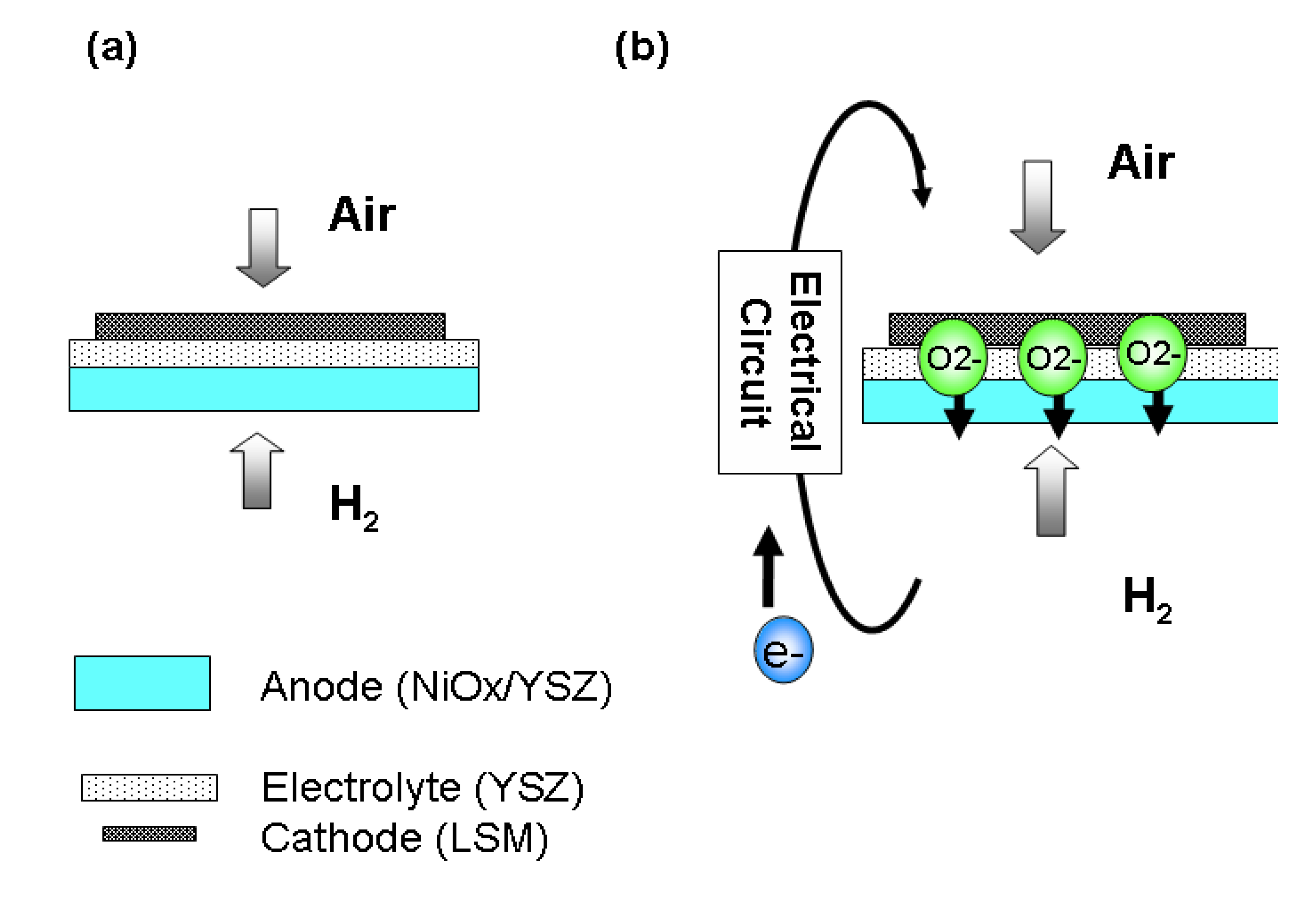
2.1. Fabrication of Anode Supported Cell

Green films of an electrolyte tape (42400, 8 mol% YSZ, thickness =15–20 μm, ESL ElectroScience Co. Inc., King of Prussia, PA, USA), one anode function layer tape (42420, NiO/YSZ = 30 wt%/70 wt%, thickness = 15–20 μm, ESL Electro-Science Co. Ltd.), and four porous anode tapes (42421, NiO/YSZ = 30 wt%/70 wt%, thickness =180 μm, ESL Electro-Science Co. Ltd.) were cut to the dimensions of 50 mm × 50 mm. The three kinds of tapes were stacked (electrolyte-top, anode function layer-middle, porous anode-bottom) and then laminated via hot-pressurization at 21 Mpa, 70 °C and maintained for 20 min. The firing profiles are as follows: (a) first firing step from 25 °C to 650 °C with the heating rate controlled at 0.9–1.1 °C/min; (b) second firing step from 650 °C to 1400 °C with the heating rate controlled at 3–5 °C/min; (c) third, the cell was maintained at target temperatures for another 120 min; (d) The final step was natural cooling to room temperature. After that, (La, Sr)MnO3(LSM) paste (42400, ESL Electro-Science Co. Ltd.) and Pt paste (42401, ESL Electro-Science Co. Ltd.), selected as target and reference cathode material, respectively, were printed onto the electrolyte/anode function layer/porous anode pellets with 40 mm × 40 mm area. The anode-supported cell with reference Pt cathode was then fired at 985 °C and maintained for 15 min, and those with the target LSM cathode were then fired at 1200 °C and maintained for 120 min. The final steps of these two sintered anode-supported cells were then cooled to room temperature naturally. Both the reference Pt and target LSM cathode thickness are maintained at around 30 µm after firing.

2.2. Different Pretreatments and Testing on the Anode Supported Cell with LSM Cathode

Electrochemical measurements of theanode supported cell were performed in a stainless steel (310S) test fixture placed inside the furnace. In order to obtain sufficient electronic contact between the cell and the electronic devices, Au meshes were used on both side of the anode and the cathode. Sealing of the gas compartment was performed by a YSZ fiber doped with YSZ powder (ZIRCAR Ceramics, Inc., Florida, NY, USA). At the beginning of the tests, an argon flow was introduced at the anode side and an oxygen flow at the cathode side. The temperature was then slowly increased to the desired temperature (500 °C) for anode pretreatment. After reaching this temperature, the anode of the anode-supported cell was reduced by a stepwise replacement of argon by 10 vol% hydrogen. The total gas flows of Ar (10 vol% H2) and oxygen were both set at 300 mL/min (standard temperature and pressure: STP) using mass flow controllers. Before cell testing, two methods were utilized for anode pretreatment. Figure 1a shows pretreatment via open-circuit and Figure 1b shows pretreatment via closed-circuit with constant current (25 mA). The biggest difference of these two pretreatments was to let the oxygen ions move freely within the anode structure via closed-circuit. Three pretreatment periods including 1 min, 60 min and 120 min were used for both closed-circuit pretreatment and open-circuit pretreatment. All electrochemical data obtained after the pretreatments include DC methods (using a current-control power supply and a computer-controlled data acquisition system) and AC impedance. The current-voltage characteristics were measured with increasing the current load by a sequential step change of 0.05 V starting from 1.0 V until the voltage dropped below 0.2 V. A chi604a electrochemical analyzer (CH Instruments Inc., Austin, TX, USA) was used. The frequency range analyzed was from 10 mHz to 10 kHz and the amplitude was 10 mV. All the impedance data were obtained at OCV. The purpose of this section is to investigate the difference (IV, AC) of the anode-supported cell with the LSM cathode after different pretreatment periods under different methods.
Figure 1. Anode pretreatments via: (a) open-circuit; (b) closed-circuit proposed by this study.
Energies 07 03922 g001

2.3. Different Pretreatments and Testing on Anode Supported Cell with Pt Cathode

Except for the anode-supported cell with Pt cathode utilized in this section, all the pretreatments and testing are the same as in Section 2.2. The purpose of this section is to investigate the difference (IV, AC) of the anode-supported cell with Pt cathode after different pretreatment periods under different methods. By comparison of this and Section 2.2, the effect of pretreatments on the NiO/YSZ anode alone could be further identified.

3. Results and Discussion

3.1. Effect of Pretreatments on NiO-YSZ/YSZ/LSM

The SOFCs that run at high temperature do not yield any performance immediately upon start-up and they need pretreatment to attain stable and high performance. In our experiments, the anode structures were almost completely in an oxide state when they were fabricated. Therefore, we first tested the effect of pretreatment by placing an anode-supported cell in dilute H2 at 500 °C. As shown in Figure 2, the performance of the initially treated anode-supported cell was very poor (2 mA/cm2 @ 0.4 V).
Figure 2. Effect of pretreatment method and time on the performance of the supported anode.
Energies 07 03922 g002
After it was pretreated for 2 h under open-circuit conditions, its performance increased steadily from 2 to 13 mA/cm2 at 0.4 V. The improvement in performance by pretreatment under open-circuit conditions is ascribed to changes in the anode structure caused by reduction of NiO to Ni in the chemical reduction environment [13]. With this transition, the dense NiO/YSZ anode layer changes to a less dense one. Pores appear in the neighborhood of Ni particles, which can promote the diffusion of fuel gas. In addition, the cell voltage increased from 0.9 to 1.05 V under open-circuit conditions at the beginning of the pretreatment, meaning Ni particles are put into function once reduced from NiO. In addition, the polarization is believed to be reduced by the increasing triple phase boundary (TPB) at which an electrochemical reaction occurs. Gradually, the anode inner-layer morphology, including the TPB lengths, determines the cell performance.
In addition to force, the air and dilute H2 through cathode and anode side, the connection between two platinum wires (connecting cathode and anode) is established with a constant resistance, making oxygen ion transportation occur freely and NiO reduction electrochemically. The external resistance between anode and cathode was chosen so that the current was maintained at 25 mA for the entire pretreatment. As shown in Figure 2 under closed-circuit conditions, its performance increased sharply from 2 to 19 mA/cm2 at 0.4 V. With 2 h pretreatment under closed-circuit conditions, the cell performance increased almost 50% compared with open-circuit conditions (Figure 2). NiO particles on the anode surface tend to reduce to Ni easily with the production of porosities (or oxygen vacancies, Vo) at the beginning. However, the reduction becomes slower because H2 penetration through the dense NiO/YSZ meets greater difficulties. Therefore, only NiO present in the few sublayers close to the anode surface is capable of reducing to Ni and come up with a limited triple-phase boundary in the anode structure. However, with the help of closed-circuit treatment, oxygen vacancies are freely transported from the anode to the cathode (in the opposite direction of oxygen ions, O2−) within the anode structure. Therefore, reduced Ni on the surface may be further transformed into NiO (Ni + O2− → NiO + 2e), while the NiO in the deeper interlayer may reduce to Ni (NiO → Ni + Vo + 2e). In other words, the oxygen vacancies move from the surface layer (Ln) to the inner layer (Ln+1). Therefore, a broader porosity is generated within the anode resulting in an increase in the triple phase boundary length in the structure and an enhancement in performance [10].

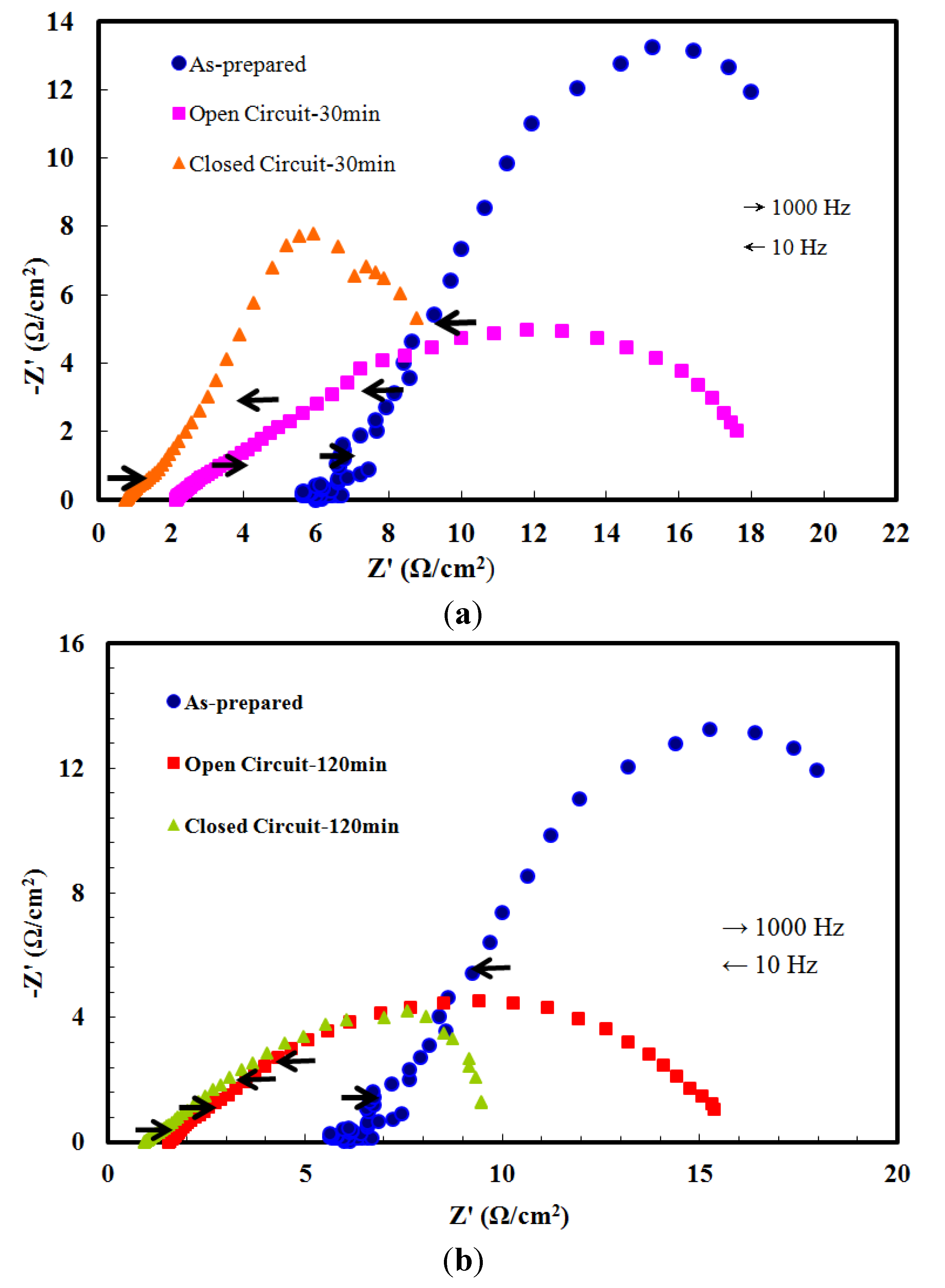
3.1.1. Characterization by AC Impedance Spectroscopy- NiO-YSZ/YSZ/LSM

To further analyze the effects of different pre-treatments on the anode-supported cell, an AC impedance test was performed. The operating parameters included a scanning frequency from 10 kHz to 10 mHz. With a suitable model fitted, the electrical resistance could be separated into cell resistance, activation resistance (cathode and anode), and concentration resistance. As shown in Figure 3a, the cell resistances were 6 Ω/cm2, 2.163 Ω/cm2 and 0.981 Ω/cm2 for as-prepared, open-circuit pretreatment (30 min), and closed-circuit pretreatment (30 min), respectively, under high frequency operation. Also, the cathode activation resistances were 21.3 Ω/cm2, 18.5 Ω/cm2 and 10.5 Ω/cm2 for as-prepared, open circuit pre-treatment (30 min), and closed circuit pre-treatment (30 min), respectively, under low frequency operation. As the pretreatment time was further extended to 120 min, the cell resistances were 1.568 Ω/cm2 and 0.772 Ω/cm2 for open-circuit pretreatment (120 min), and closed-circuit pretreatment (120 min), respectively. In addition, the cathode activation resistances were 15.8 Ω/cm2 and 9.5 Ω/cm2 for open-circuit pretreatment (120 min), and closed-circuit pre-treatment (120 min), respectively, under low frequency operation. Comparing with the cell resistance and cathode activation resistances of as-prepared anode supported cell, those with pretreatments decreased obviously, with the effect of closed-circuit pretreatment being more profound.
Figure 3. Impedance spectra of anode supported cell with as-prepared, open-circuit and closed-circuit pretreatment: (a) 30 min; (b) 120 min.
Energies 07 03922 g003

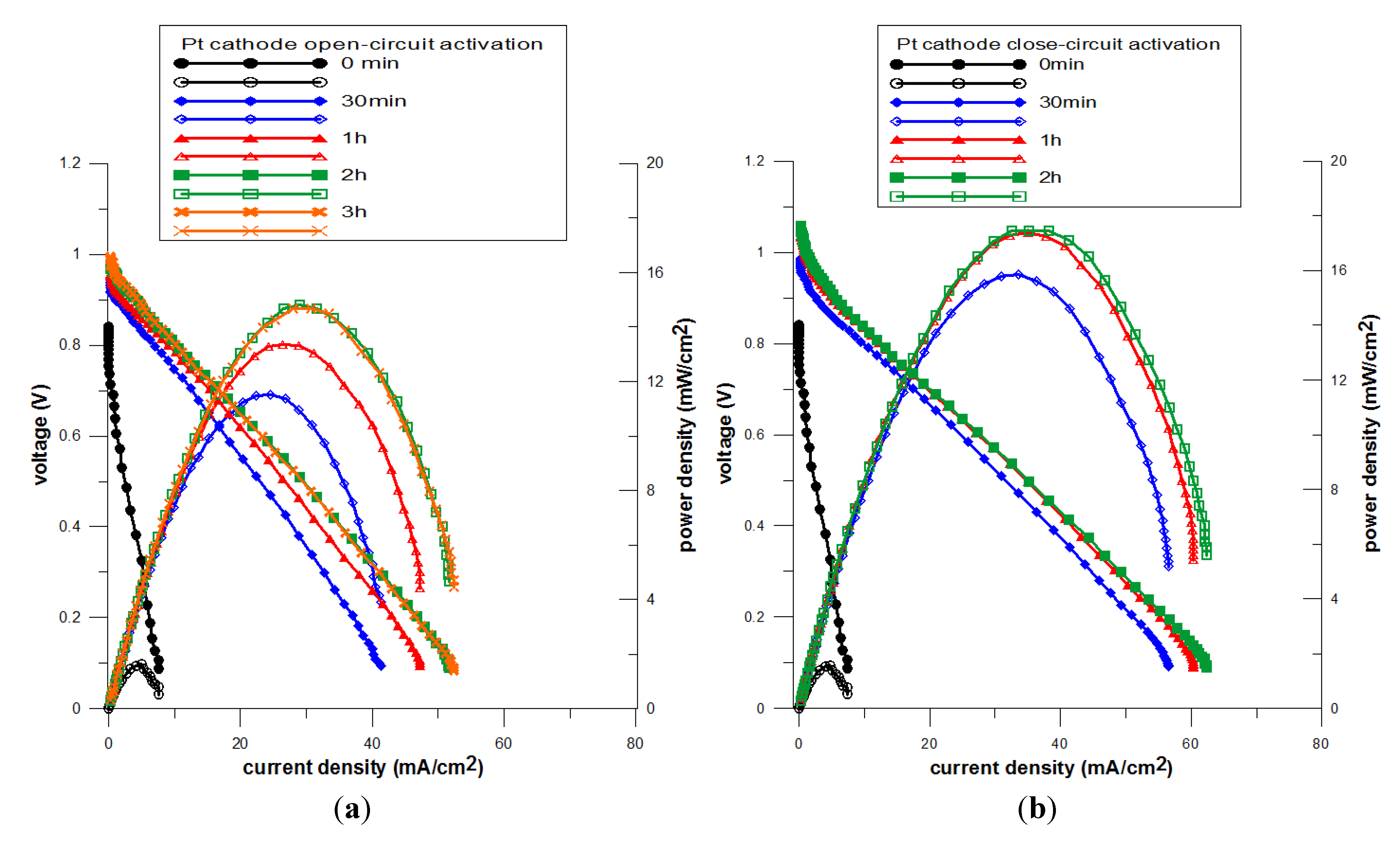
3.2. Effect of Pretreatments on NiO-YSZ/YSZ/Pt

In this section, the effects of pretreatments on the anode-supported cell with Pt cathode are characterized by IV and AC impedance. As shown in Figure 4a, the current densities at 0.4 V are 3.8, 27.6, 32.3, 35.2 and 35.2 mA/cm2 for open-circuit pre-treatment times of 0 min, 30 min, 1 h, 2 h and 3 h, respectively. It takes around 2 h to complete 91.7% (32.3/35.2) of pre-treatment. As shown in Figure 4b, current densities at 0.4 V are 4.06, 37.81, 42.19 and 43.20 mA/cm2 for closed-circuit pre-treatment times of 0 min, 30 min, 1 h, 2 h, respectively. It takes around 30 min to complete 89.7% (37.81/43.20) of pre-treatment. Obviously, comparing with those of open-circuit pre-treatment, closed-circuit pre-treatment is more efficient (89.7% for 30 min vs. 91.7% for 2 h) and complete (43.20 mA/cm2vs. 35.2 mA/cm2).
Figure 4. Effect of pretreatment time on the performance of SOFC with Pt cathode: (a) open-circuit; (b) closed-circuit.
Energies 07 03922 g004

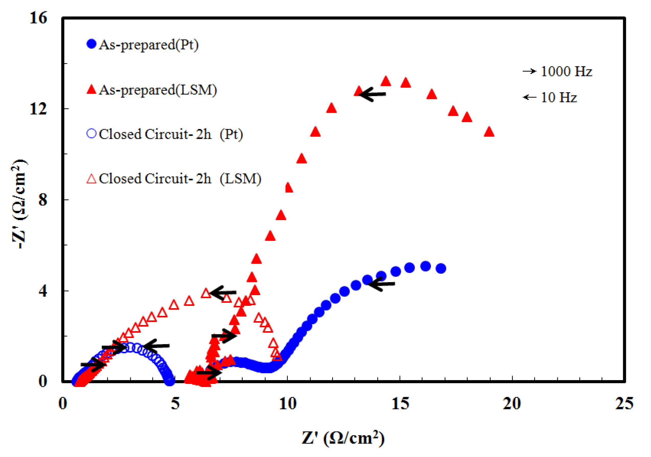
3.2.1. Characterization by AC Impedance Spectroscopy- NiO-YSZ/YSZ/Pt

To further analyze the effects of different pretreatments on the anode supported cell with Pt cathode, an AC impedance test was performed. The operating parameters included a scanning frequency from 10 kHz to 10 mHz. With a suitable model fitted, the electrical resistance could be separated into cell resistance, activation resistance, and concentration resistance. As shown in Figure 5a, the cell resistances with open-circuit pre-treatment were 6.23, 0.88, 0.81 and 0.62 Ω/cm2 for as-prepared, 30 min, 60 min and 120 min, respectively, under high frequency operation. Also, the cathode activation resistances were 25, 8.3, 8.1 and 7.2 Ω/cm2 for as-prepared, 30 min, 60 min and 120 min, respectively, under low frequency operation. As shown in Figure 5b, the cell resistances with closed-circuit pre-treatment were 6.23, 0.87, 0.75 and 0.61 Ω/cm2 for as-prepared, 30 min, 60 min and 120 min, respectively, under high frequency operation. Also, the cathode activation resistances were 25, 6.45, 4.35 and 4.15 Ω/cm2 for as-prepared, 30, 60 and 120 min, respectively, under low frequency operation.
Comparing with the cell resistance of the anode-supported cell with open-circuit pretreatment, those with closed-circuit pretreatment decreased slightly more. As for the cathode activation resistances, however, the anode-supported cell with closed-circuit pretreatments decreased more than those with open-circuit pretreatments. Comparing with Section 3.1, even with Pt cathode, the cathode activation resistance still decreased faster, meaning that an oxide LSM and metallic Pt cathode structure after closed–circuit pretreatment is more favourable for O2 reduction than open circuit pre-treatment.
Figure 5. Impedance spectra of anode supported cell with Pt cathode with: (a) open-circuit; (b) closed-circuit pretreatment.
Energies 07 03922 g005

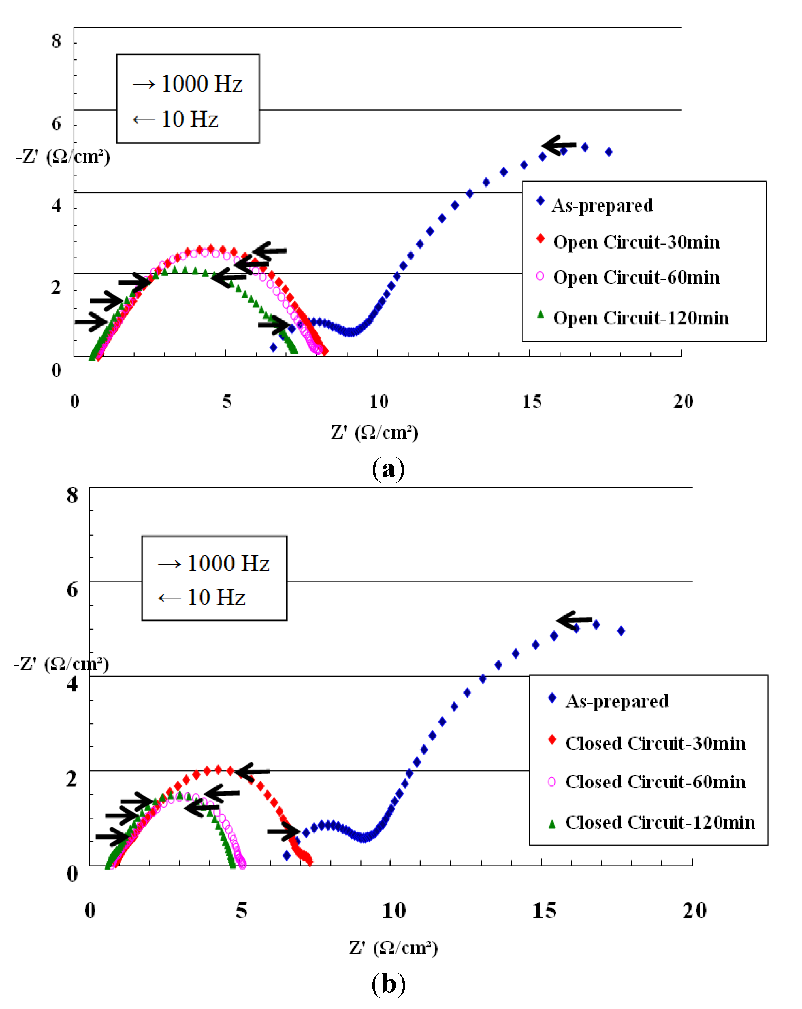
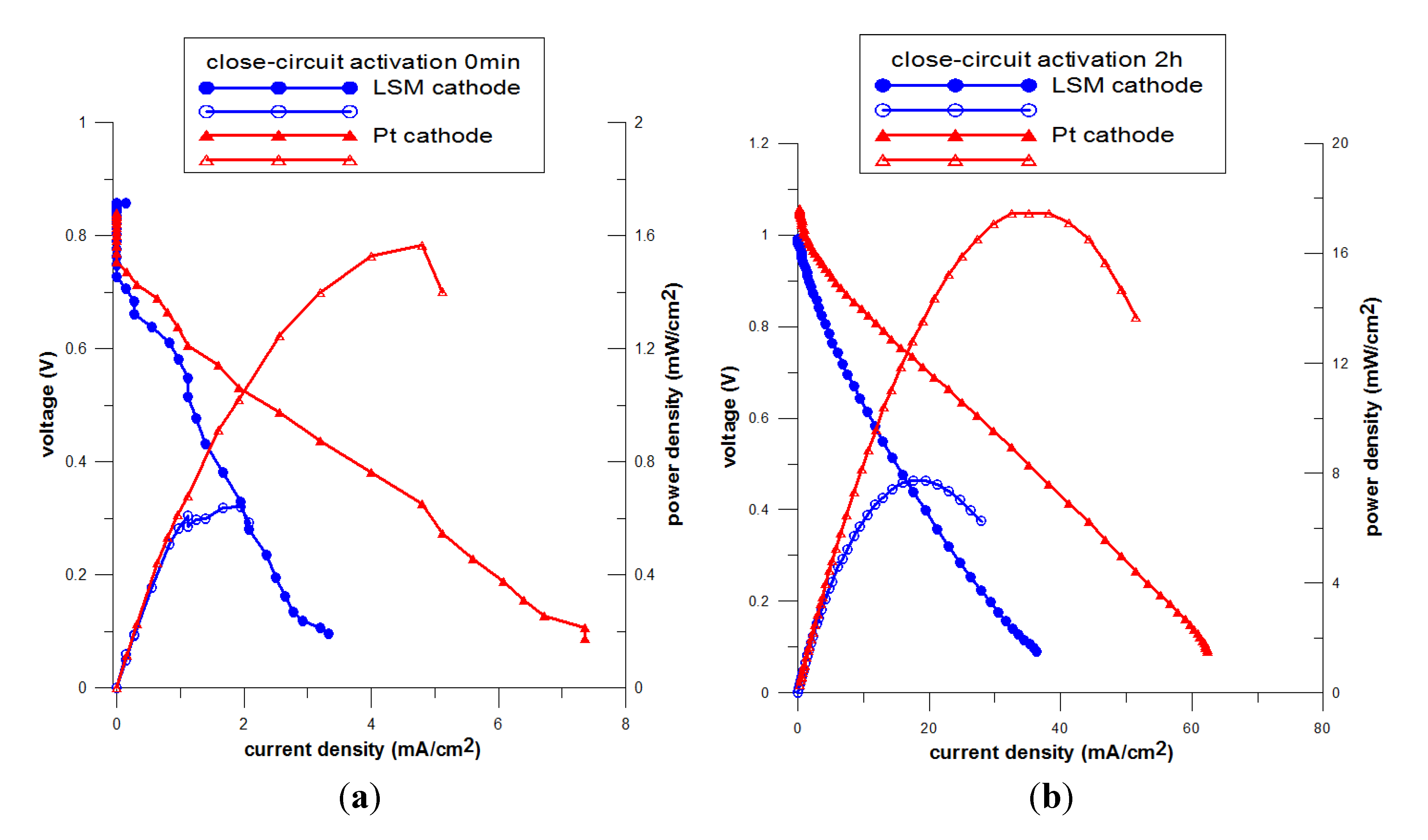
3.3. Effect of Closed-Circuit Pre-Treatment on NiO-YSZ/YSZ/LSM and NiO-YSZ/YSZ/Pt

We can conclude from the experimental data in Section 3.1 and Section 3.2, that the performance improvement of NiO-YSZ/YSZ/LSM and NiO-YSZ/YSZ/Pt with closed-circuit pretreatment has been proved to be contributed to highly by the oxide LSM and metallic Pt cathode. In this section, the effects of closed-circuit pre-treatment on NiO-YSZ/YSZ/LSM and NiO-YSZ/YSZ/Pt were further examined by IV and AC impedance. As shown in Figure 6a, current densities at 0.4 V are 1.8 and 3.9 mA/cm2 for NiO-YSZ/YSZ/LSM and NiO-YSZ/YSZ/Pt before closed-circuit pretreatment, respectively. As shown in Figure 6b, current densities at 0.4 V are 19 and 41 mA/cm2 for NiO-YSZ/YSZ/LSM and NiO-YSZ/YSZ/Pt after closed-circuit pretreatment of 2 h, respectively. Whereas for as-prepared or after closed-circuit pre-treatment, performance of NiO-YSZ/YSZ/Pt is almost twice as high compared with that of NiO-YSZ/YSZ/LSM due to its better Pt conductivity and Pt catalytic-ability. As shown in Figure 7, the cell resistances were 5.5 and 6.0 Ω/cm2, for as-prepared NiO-YSZ/YSZ/LSM and NiO-YSZ/YSZ/Pt, respectively. The anode activation resistances were 10.0 and 9.5 Ω/cm2, for as-prepared NiO-YSZ/YSZ/LSM and NiO-YSZ/YSZ/Pt, respectively.
Figure 6. IV curve of NiO-YSZ/YSZ/LSM and NiO-YSZ/YSZ/Pt: (a) as-prepared; (b) after 2 h closed-circuit pretreatment.
Energies 07 03922 g006
Figure 7. AC curve of NiO-YSZ/YSZ/LSM and NiO-YSZ/YSZ/Pt.
Energies 07 03922 g007
The cathode activation resistances were 25.0 and 21.0 Ω/cm2, for as-prepared NiO-YSZ/YSZ/LSM and NiO-YSZ/YSZ/Pt, respectively. Lower cathode activation resistance associated with NiO-YSZ/YSZ/Pt is the reason it contributed to higher IV performance as shown in Figure 6a. Also as shown in Figure 7, the cell resistances were 0.9 and 0.8 Ω/cm2, for 2 h closed-circuit pretreatment on NiO-YSZ/YSZ/LSM and NiO-YSZ/YSZ/Pt, respectively. Also, the cathode activation resistances were 9.5 and 4.8 Ω/cm2, for 2 h closed-circuit pretreatment on NiO-YSZ/YSZ/LSM and NiO-YSZ/YSZ/Pt, respectively. Lower electrode activation resistance (for the cathode especially) as well as lower cell resistance of NiO-YSZ/YSZ/Pt are the main reasons that contributed to the higher IV performance as shown in Figure 7.

4. Conclusions

At this point of the study, low performances and high resistance presented due to the dilute H2 used and lower operation temperature especially designed in this study. The results successfully confirm the feasibility of SOFC being activated via different pretreatment methods. Although both anode and cathode could benefit from closed-circuit pretreatment, the fact that pretreatment via closed-circuit was more effective than that using traditional open-circuit conditions indicates that for oxide LSM or metallic Pt, the cathode structure is more favourable for O2 reduction after closed-circuit pretreatments.

Acknowledgments

The authors gratefully thank the National Science Council of Taiwan under contracts NSC 99-2221-E-155-063 and NSC 100-3113-E-155-001 and the Taiwan Power Company for the financial support.

Nomenclature

A
current
I
current density, A/cm2
P
power density, W/cm2
Z
resistance, Ω/cm2
−Z
resistance, Ω/cm2
Vo
oxygen vacancy
T
temperature, °C
t
time, min
V
voltage

Conflicts of Interest

The authors declare no conflict of interest.

References

  1. Najafi, B.; Shirazi, A.; Aminyavari, M.; Rinaldi, F.; Taylor, R.A. Exergetic, economic and environmental analyses and multi-objective optimization of an SOFC-gas turbine hybrid cycle coupled with an MSF desalination system. Desalination 2014, 334, 46–59. [Google Scholar] [CrossRef]
  2. Shirazi, A.; Aminyavari, M.; Najafi, B.; Rinaldi, F.; Razaghi, M. Thermal-economic-environmental analysis and multi-objective optimization of an internal-reforming solid oxide fuel cell-gas turbine hybrid system. Int. J. Hydrog. Energy 2012, 37, 19111–19124. [Google Scholar] [CrossRef]
  3. Saribog, V.; Öksüzömer, F. The investigation of active Ni/YSZ interlayer for Cu-based direct-methane solid oxide fuel cells. Appl. Energy 2012, 93, 707–721. [Google Scholar]
  4. Yan, W.M.; Wang, X.D.; Lee, D.J.; Zhang, X.X.; Guo, Y.F.; Su, A. Experimental study of commercial size proton exchange membrane fuel cell performance. Appl. Energy 2011, 88, 392–396. [Google Scholar] [CrossRef]
  5. Ha, S.; Rice, C.A.; Masel, R.I.; Wieckowski, A. Methanol conditioning for improved performance of formic acid fuel cells. J. Power Sources 2002, 112, 605–609. [Google Scholar] [CrossRef]
  6. Cassidy, M.; Lindsay, G.; Kendall, K. The reduction of nickel-zirconia cermet anodes and the effects on supported thin electrolytes. J. Power Sources 1996, 6, 189–192. [Google Scholar] [CrossRef]
  7. Wang, Y.; Walter, M.E.; Sabolsky, K.; Seabaugh, M.M. Effects of power sizes and reduction parameters on the strength of Ni-YSZ anodes. Solid States Ion. 2006, 177, 1517–1527. [Google Scholar] [CrossRef]
  8. Jiang, S.P.; Love, J.G.; Zhang, J.P.; Hoang, M.; Ramprakash, Y.; Hughes, A.E.; Badwal, S.P.S. The electrochemical performance of LSM/zirconia–yttria interface as a function of A-site non-stoichiometry and cathodic current treatment. Solid State Ion. 1999, 121, 1–10. [Google Scholar] [CrossRef]
  9. Lee, H.Y.; Cho, W.S.; Oh, S.M.; WiemhVofer, H.D.; Gvopel, W. Active reaction sites for oxygen reduction in La0.9Sr0.1MnO3/YSZ electrodes. J. Electrochem. Soc. 1995, 142, 2659–2664. [Google Scholar] [CrossRef]
  10. Jiang, S.P.; Love, J.G. Origin of the initial polarization behavior of Sr-doped LaMnO3 for O2 reduction in solid oxide fuel cells. Solid State Ion. 2001, 138, 183–190. [Google Scholar] [CrossRef]
  11. Haanappel, V.A.C.; Mai, A.; Mertens, J. Electrode activation of anode-supported SOFCs with LSM- or LSCF-type cathodes. Solid State Ion. 2006, 177, 2033–2037. [Google Scholar] [CrossRef]
  12. Jung, G.B.; Lo, K.F.; Chan, S.H. Effect of pretreatments on the anode structure of solid oxide fuel cells. J. Solid State Electrochem. 2007, 11, 1435–1440. [Google Scholar] [CrossRef]
  13. Cai, Z.; Lan, T.N.; Wang, S.; Dokiy, M. Supported Zr(Sc)O2 SOFCs for reduced temperature prepared by slurry coating and co-firing. Solid State Ion. 2002, 152, 583–590. [Google Scholar] [CrossRef]

