Solar Air Collectors for Space Heating and Ventilation Applications—Performance and Case Studies under Romanian Climatic Conditions †

Abstract
:1. Introduction
2. Experimental Research
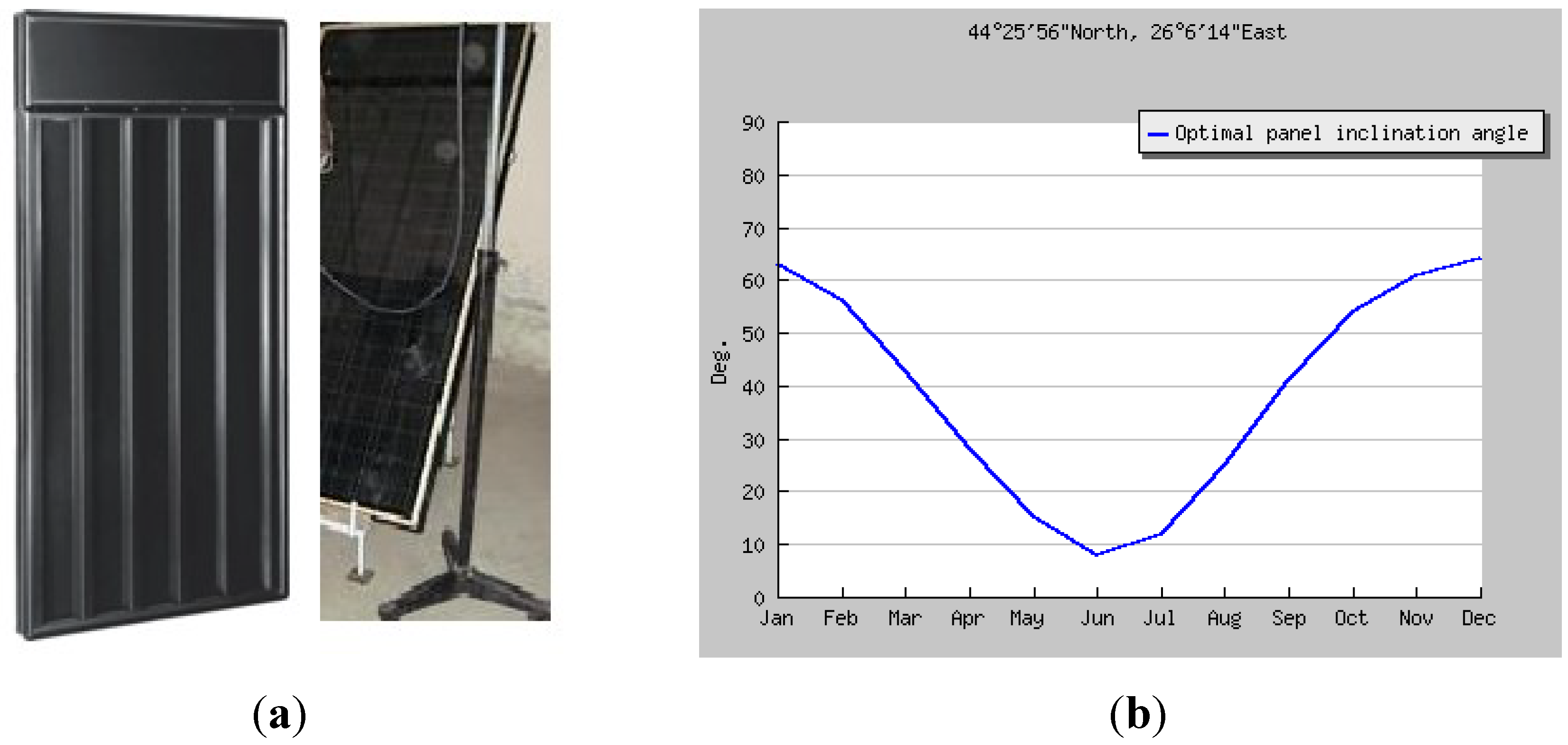
2.1. Characteristics of the Solar Air Collector
2.2. Test Setup

2.3. Mathematical Modeling
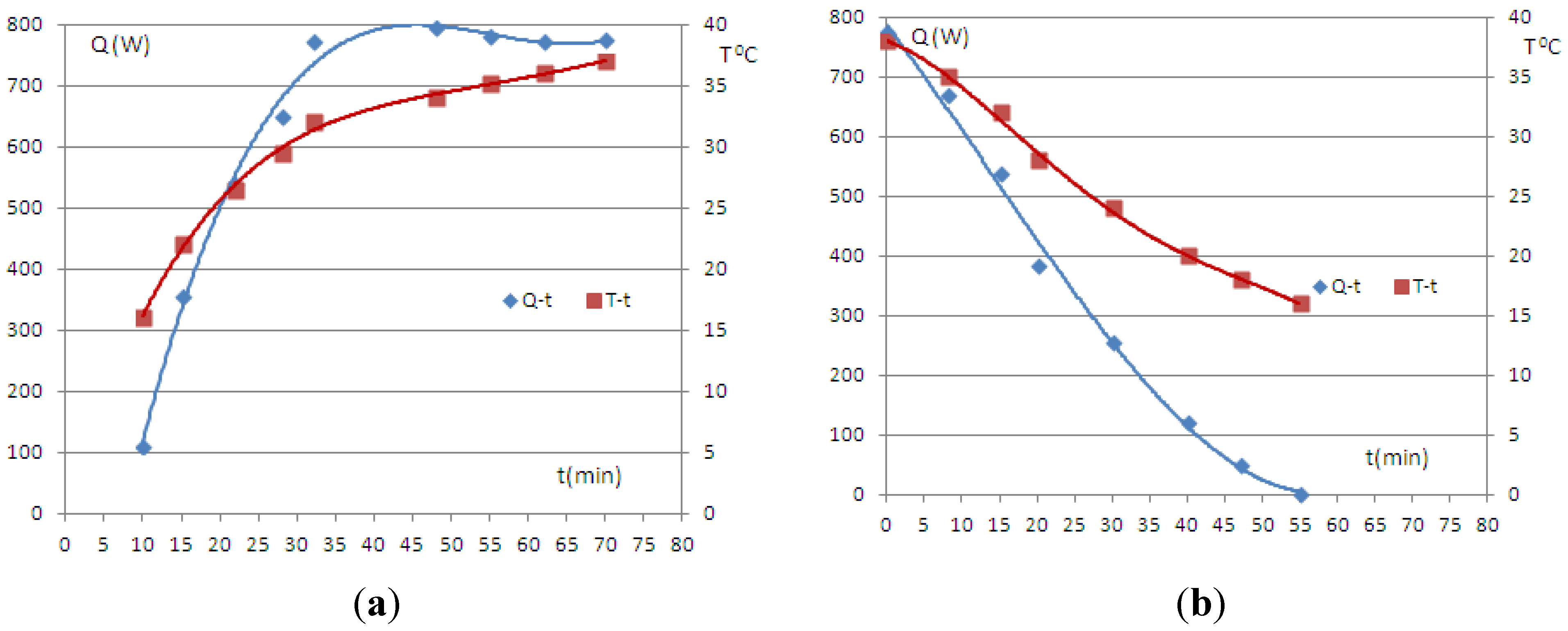
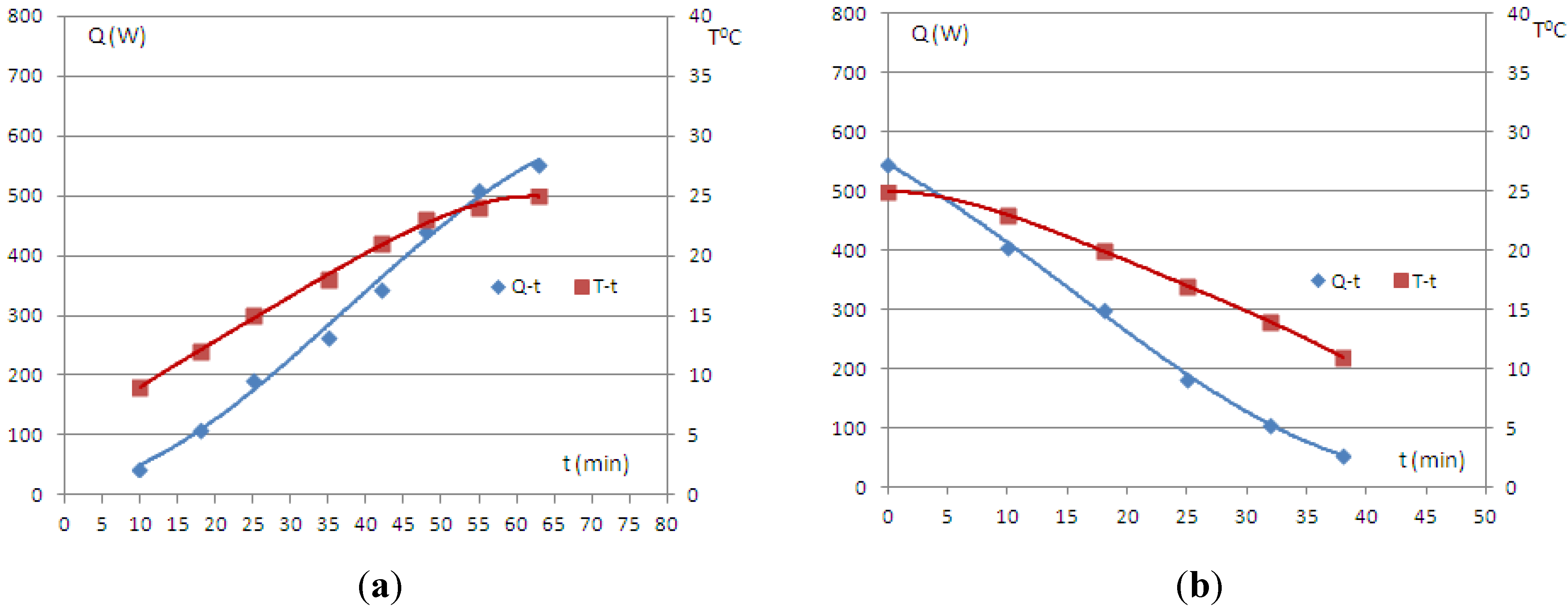
2.4. Results and Analysis


3. Applications of Solar Collectors in Ventilation of Spaces
3.1. Computation Models for Natural Ventilation
3.2. Case Studies

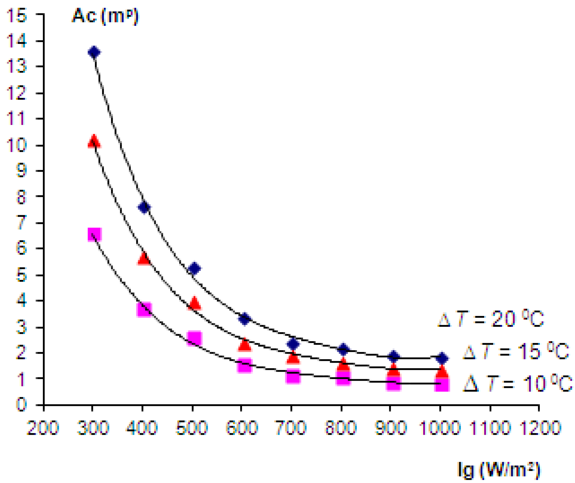
| Ig (W/m2) | v (m/s) | η (-) | ΔT (°C) | Ac (m2) | ΔT (°C) | Ac (m2) | ΔT (°C) | Ac (m2) |
|---|---|---|---|---|---|---|---|---|
| 300 | 1.2 | 0.09 | 10 | 6.59 | 15 | 10.22 | 20 | 13.62 |
| 400 | 1.5 | 0.15 | 10 | 3.7 | 15 | 5.75 | 20 | 7.66 |
| 500 | 1.75 | 0.2 | 10 | 2.59 | 15 | 4.02 | 20 | 5.36 |
| 600 | 1.85 | 0.28 | 10 | 1.56 | 15 | 2.43 | 20 | 3.41 |
| 700 | 2 | 0.36 | 10 | 1.18 | 15 | 1.93 | 20 | 2.43 |
| 800 | 2.4 | 0.42 | 10 | 1.06 | 15 | 1.64 | 20 | 2.19 |
| 900 | 2.6 | 0.46 | 10 | 0.89 | 15 | 1.44 | 20 | 1.93 |
| 1000 | 3 | 0.5 | 10 | 0.83 | 15 | 1.38 | 20 | 1.84 |
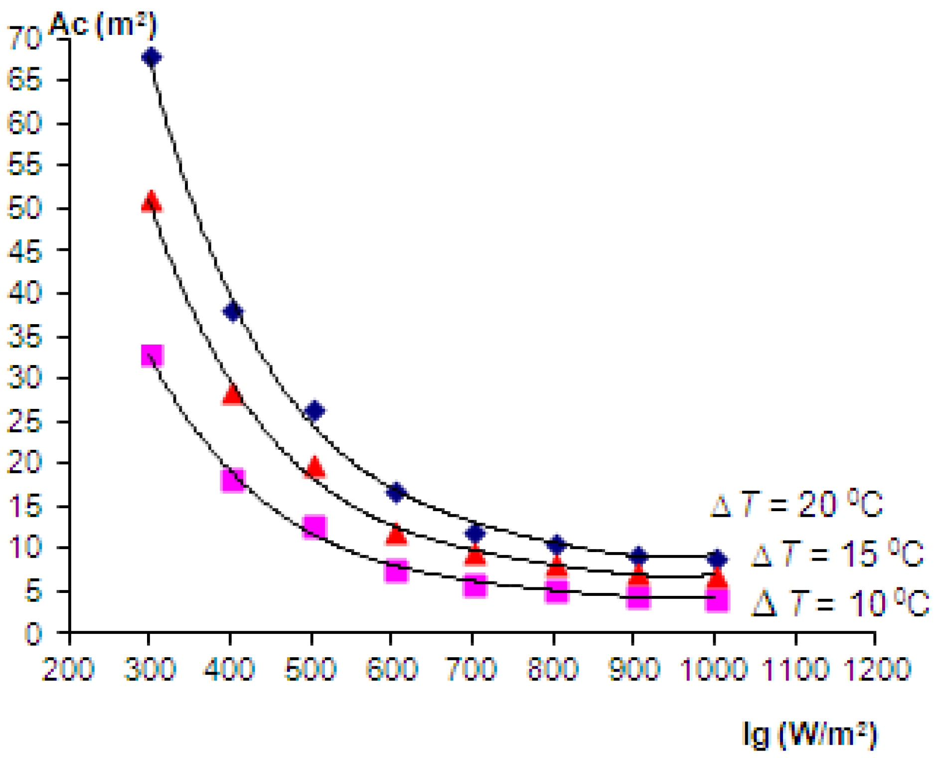
| Ig (W/m2) | V (m/s) | η (-) | ΔT (°C) | Ac (m2) | ΔT (°C) | Ac (m2) | ΔT (°C) | Ac (m2) |
|---|---|---|---|---|---|---|---|---|
| 300 | 1.2 | 0.09 | 10 | 32.95 | 15 | 51.1 | 20 | 68.1 |
| 400 | 1.5 | 0.15 | 10 | 18.5 | 15 | 28.75 | 20 | 38.3 |
| 500 | 1.75 | 0.2 | 10 | 12.95 | 15 | 20.1 | 20 | 26.8 |
| 600 | 1.85 | 0.28 | 10 | 7.8 | 15 | 12.15 | 20 | 17.05 |
| 700 | 2 | 0.36 | 10 | 5.9 | 15 | 9.65 | 20 | 12.15 |
| 800 | 2.4 | 0.42 | 10 | 5.3 | 15 | 8.2 | 20 | 10.95 |
| 900 | 2.6 | 0.46 | 10 | 4.45 | 15 | 7.2 | 20 | 9.65 |
| 1000 | 3 | 0.5 | 10 | 4.15 | 15 | 6.9 | 20 | 9.2 |

4. Conclusions
Notation
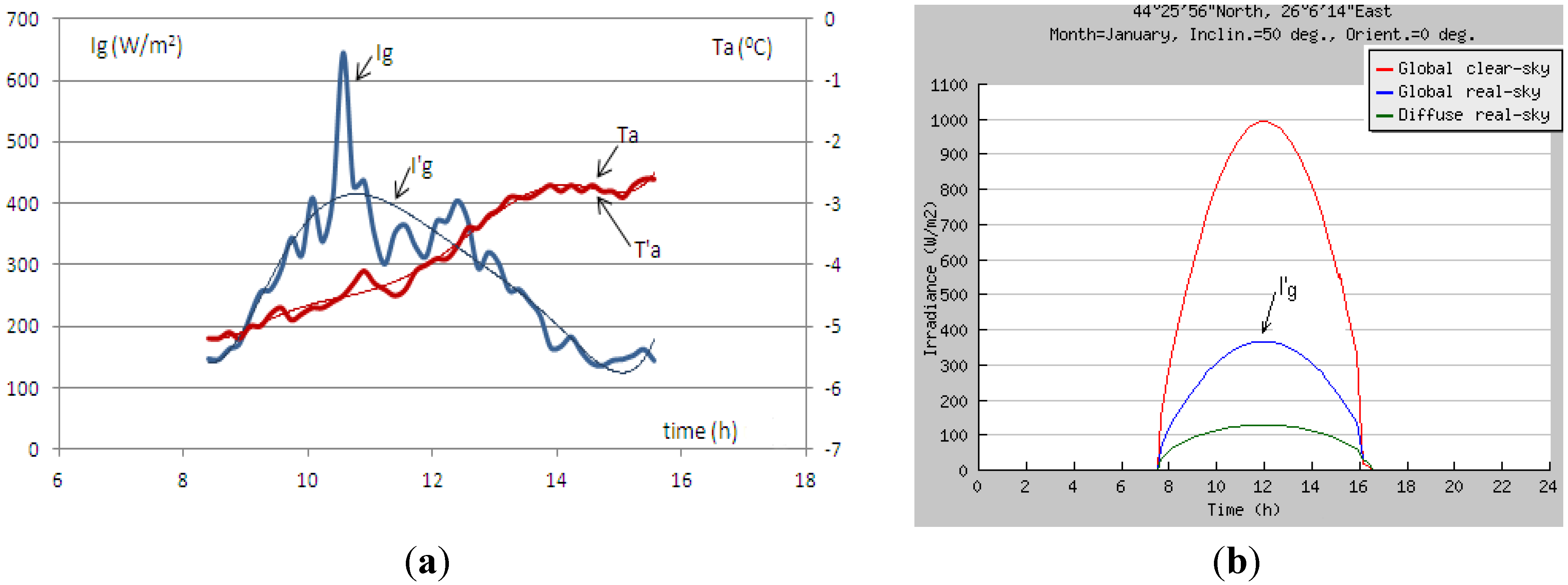
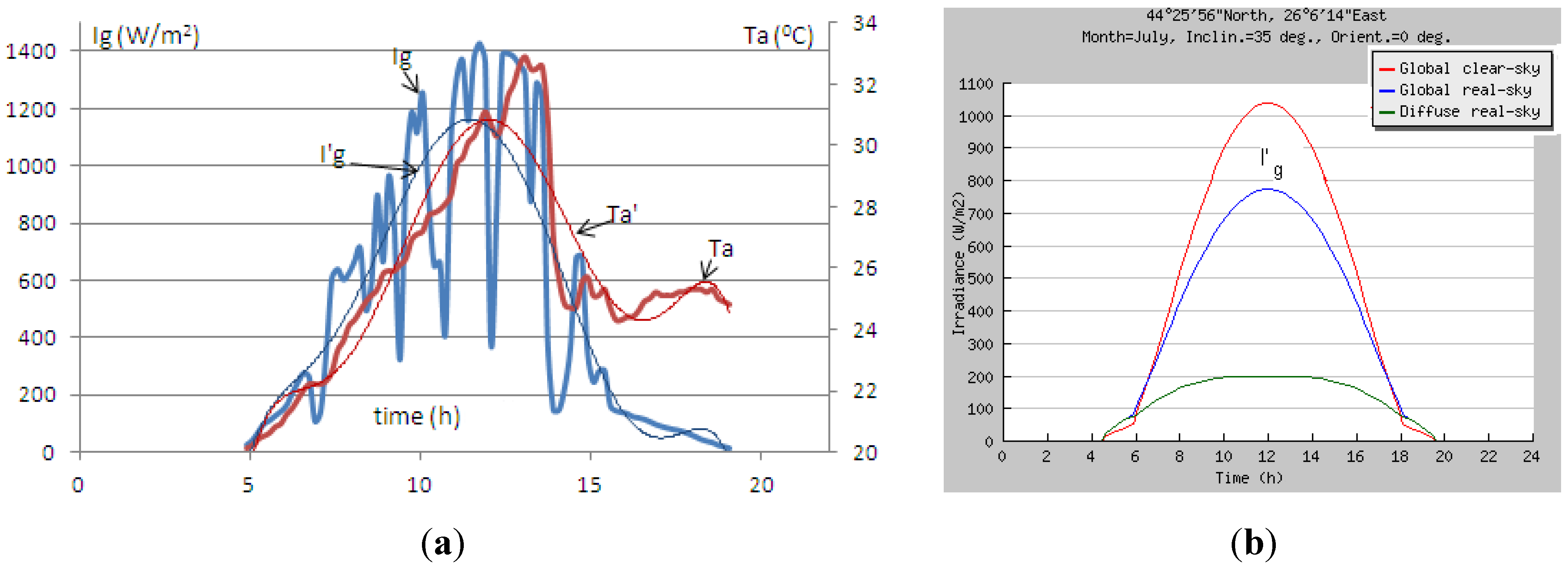
| Ig | global solar irradiance on tilted plane (W/m2) |
| Ig | interpolated values of solar irradiance |
| Ta | atmospheric temperature (°C) |
| T’a | interpolated values of atmospheric temperature |
| Q | heat flux (W) |
| cp | the specific heat of air at constant pressure (kJ/kgK) |
| m | mass flow rate (kg/s) |
| d | diameter of duct (m) |
| ⩒ | the volume of the air leaving the collector by the duct (m3) |
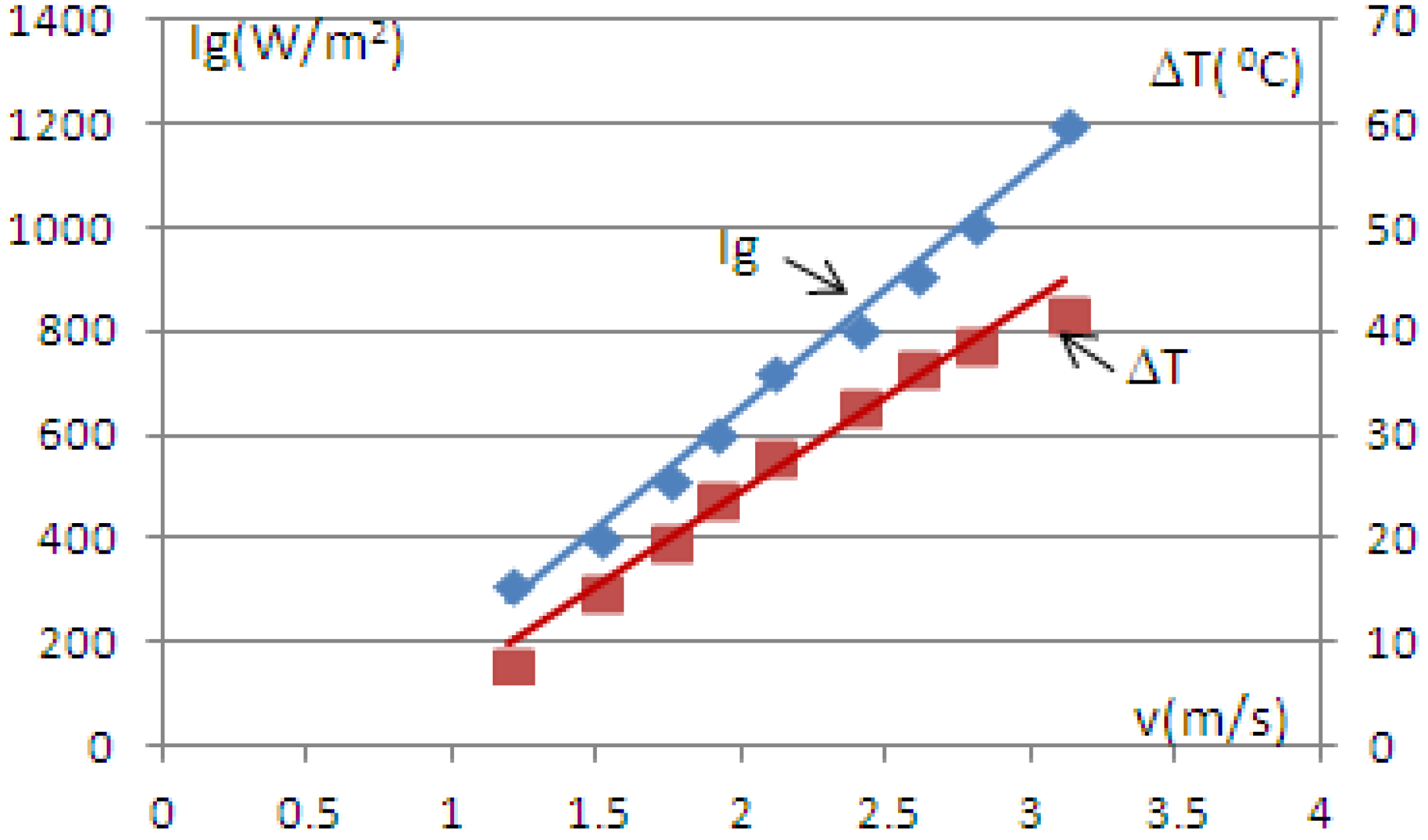
| v | the air velocity in (m/s) |
| ρ | the density of air in (kg/m3) |
| ΔT | the difference of temperature between collector outlet and inlet (°C) |
| Tfin, Tfout | temperature of the fluid to inlet/outlet of the collector (°C) |
| η | the efficiency of solar air collector |
| Ac | area of the collector (m2) |
| A0 | area of outlet section (m2) |
| L x l | dimensions of the surface of the collector (m) |
| b | collector thickness (m) |
| ACH | air change per hour |
| Vr | volume of the room/ventilated space (m3) |
Conflicts of Interest
References
- Chiou, J.P.; El-Wakil, M.M.; Duke, J.A. A slit-and-expanded aluminum-foil matrix solar collectors. Solar Energy 1965, 9, 73–80. [Google Scholar] [CrossRef]
- Hachemi, A. Technical note comparative study on the thermal performances of solar air heater collectors with selective absorber plate. Renew. Energy 1999, 17, 103–112. [Google Scholar] [CrossRef]
- Biondi, P.; Cicala, L.; Farina, G. Performance analysis of solar air heaters of conventional design. Solar Energy 1988, 41, 101–107. [Google Scholar] [CrossRef]
- Gupta, D.; Solanki, S.C.; Saini, J.S. Heat and fluid flow in rectangular solar air heater ducts having transverse rib roughness on absorber plates. Solar Energy 1993, 51, 31–37. [Google Scholar] [CrossRef]
- El-Sawi, A.M.; Wifi, A.S.; Younan, M.Y.; Elsayed, E.A.; Basily, B.B. Application of folded sheet metal in flat bed solar air collectors. Appl. Therm. Eng. 2010, 30, 864–871. [Google Scholar] [CrossRef]
- Lanjewar, A.; Bhagoria, J.L.; Sarviya, R.M. Experimental study of augmented heat transfer and friction in solar air heater with different orientations of W-Rib roughness. Exp. Therm. Fluid Sci. 2011, 35, 986–995. [Google Scholar] [CrossRef]
- Krzaczek, M.; Kowalczuk, Z. Thermal Barrier as a technique of indirect heating and cooling for residential buildings. Energy Build. 2011, 43, 823–837. [Google Scholar] [CrossRef]
- Chan, H.Y.; Riffat, S.B.; Zhu, J. Review of passive solar heating and cooling technologies. Renew. Sustain. Energy Rev. 2010, 14, 781–789. [Google Scholar] [CrossRef]
- Active solar air heating systems. Education of Architects in Solar Energy and Environment. Section 2.4. pp. 1–22. Available online: http://www-cenerg.ensmp.fr/ease/active_overheads.pdf (accessed on 10 February 2014).
- Morson, I. Performance Review of the SH 1500G Solar Air Heater; Ryerson University: Toronto, ON, Canada, 2007. Available online: http://www.yoursolarhome.com (accessed on 10 February 2014).
- Ciocănea, A.; Dragomirescu, A.; Budea, S. Experimental research on transient regimes of solar air heat collectors. Environ. Eng. Manag. J. 2011, 10, 1097–1103. [Google Scholar]
- Romdhane, B.S. The air solar collectors: Comparative study, introduction of baffles to favor the heat transfer. Solar Energy 2007, 81, 139–149. [Google Scholar] [CrossRef]
- Ramani, B.M.; Gupta, A.; Kumar, R. Performance of a double pass solar air collector. Solar Energy 2010, 84, 1929–1937. [Google Scholar] [CrossRef]
- JRC. PVGIS. Available online: http://re.jrc.ec.europa.eu/pvgis/apps4/pvest.php?lang=en&map=europe (accessed on 10 February 2014).
- Visagavel, K.; Srinivasan, P.S.S. Experimental investigation on solar air heater assisted natural ventilation in single side ventilated room. Indian J. Sci. Technol. 2010, 3, 802–806. [Google Scholar]
- Fraisse, G.; Johannes, K.; Trillat-Berdal, V.; Achard, G. The use of a heavy internal wall with a ventilated air gap to store solar energy and improve summer comfort in timber frame houses. Energy Build. 2006, 38, 293–302. [Google Scholar] [CrossRef]
- Zhai, X.Q.; Dai, Y.J.; Wang, R.Z. Comparison of heating and natural ventilation in a solar house induced by two roof solar collectors. Appl. Therm. Eng. 2005, 25, 741–757. [Google Scholar] [CrossRef]
- Hirunlabh, J.; Wachirapuwadon, S.; Pratinthong, N.; Khedari, J. New configurations of a roof solar collector maximizing natural ventilation. Build. Environ. 2001, 36, 383–391. [Google Scholar] [CrossRef]
- Sandberg, M.; Moshfegh, B. Ventilated-solar roof airflow and heat transfer investigation. Renew. Energy 1998, 15, 287–292. [Google Scholar] [CrossRef]
- Mathur, J.; Bansal, N.K.; Mathur, S.; Jain, M.; Anupma. Experimental investigations on solar chimney for room ventilation. Solar Energy 2006, 80, 927–935. [Google Scholar] [CrossRef]
- Bassiouny, R.; Nader, S.A. An analytical and numerical study of solar chimney use for room natural ventilation. Energy Build. 2007, 39, 128–135. [Google Scholar] [CrossRef]
© 2014 by the authors; licensee MDPI, Basel, Switzerland. This article is an open access article distributed under the terms and conditions of the Creative Commons Attribution license (http://creativecommons.org/licenses/by/3.0/).
Share and Cite
Budea, S. Solar Air Collectors for Space Heating and Ventilation Applications—Performance and Case Studies under Romanian Climatic Conditions. Energies 2014, 7, 3781-3792. https://doi.org/10.3390/en7063781
Budea S. Solar Air Collectors for Space Heating and Ventilation Applications—Performance and Case Studies under Romanian Climatic Conditions. Energies. 2014; 7(6):3781-3792. https://doi.org/10.3390/en7063781
Chicago/Turabian StyleBudea, Sanda. 2014. "Solar Air Collectors for Space Heating and Ventilation Applications—Performance and Case Studies under Romanian Climatic Conditions" Energies 7, no. 6: 3781-3792. https://doi.org/10.3390/en7063781