Priority-Based Hierarchical Operational Management for Multiagent-Based Microgrids


Abstract
: Electricity consumption in the world is constantly increasing, making our lives become more and more dependent on electricity. There are several new paradigms proposed in the field of power grids. In Japan, especially after the Great East Japan Earthquake in March 2011, the new power grid paradigms are expected to be more resilient to survive several difficulties during disasters. In this paper, we focus on microgrids and propose priority-based hierarchical operational management for multiagent-based microgrids. The proposed management is a new multiagent-based load shedding scheme and multiagent-based hierarchical architecture to realize such resilient microgrids. We developed a prototype system and performed an evaluation of the proposed management using the developed system. The result of the evaluation shows the effectiveness of our proposal in power shortage situations, such as disasters.1. Introduction
As the importance of electricity has been significantly increasing, there have been several new paradigms of power grid proposed in the field of smart grids and microgrids. Smart grids are digitally-enabled electrical grids that gather, distribute and act on information about the behavior of all participants in the electric grid. It has distributed generation systems, storage systems and loads.
Ensuring energy security to face dwindling oil and gas reserves requires a radical improvement in the way in which energy is generated, distributed and consumed. In Japan, especially after the Great East Japan Earthquake, new power grid paradigms are expected to be more sustainable and resilient to survive several difficulties during disasters [1,2].
A resilient power system is able to locate faults by collecting and analyzing the information in the power grid and to restore the functions autonomously [3–5]. It can also configure the power loads, demands and generation scheduling to survive a power shortage, intermittency, etc. [6–10].
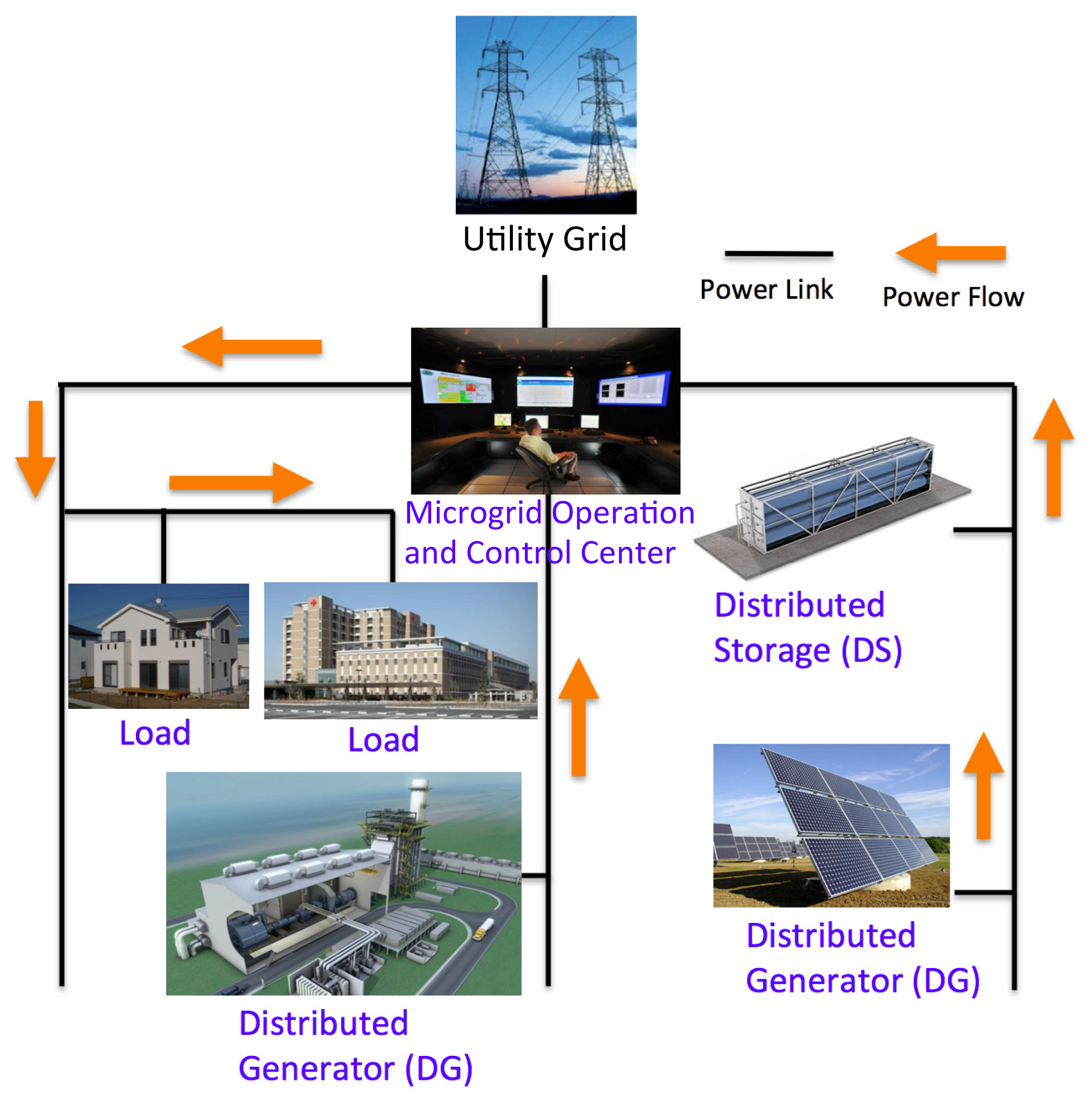
This paper focuses on microgrids, which are a small-scale power supply network designed to provide power for small communities. The overview of a microgrid is shown in Figure 1. Microgrids are connected to a utility grid, which is a conventional, larger scale power supply network, which exchanges power with the microgrid. Typically, there is only one connection between the microgrid and the utility grid. The microgrid is composed of distributed generators (DGs), distributed storage (DSs) and loads, such as commercial buildings, schools, hospitals, industrial plants, and so on [11,12]. A microgrid operation and control center (MGOCC) is in charge of gathering information in the microgrid and making decisions to operate and control the microgrid.
Since microgrids have several components to control, it is challenging to operate a microgrid in a conventional, fully centralized way. It is required that each component gathers, distributes and acts on information. Therefore, each component needs to be autonomous, reactive and cooperative to work together as a microgrid. In order to meet these criteria, applying an agent system to a microgrid is proposed in existing research, and it is well established that the application of an agent system to a microgrid is effective [11–15].
The microgrid has two operational modes: the grid connected mode and the island mode. In the grid connected mode, the power balance between the supply and demand in the microgrid is maintained by a power exchange with the utility grid. In the island mode, the microgrid is electrically isolated from the utility grid; thus, there is no power exchange. In this mode, maintaining local demand is challenging. In the case of supply shortage, load shedding [10] needs to be performed in the islanded microgrid, to reduce the amount of load. Discharging of the distributed storage is also performed to meet the balance between supply and demand.
Island mode can be intentional or happen due by accident, such as grid failure. Research has been done to distinguish between these conditions [16].
In power grid operation, performing load shedding causes a critical problem, because loads do not expect that their demands do not meet the power supply. However, if a disaster, like the Great East Japan Earthquake [2], forces a microgrid to be isolated from the utility grid, then the microgrid needs to handle the power shortage until the utility grid becomes available again. In addition, in a situation, like the scheduled rolling blackout [17] performed by Tokyo Electric Power Company (TEPCO) [18], a microgrid needs to be operated in islanded mode frequently, and it is crucial to protect important loads in the microgrid.
In this paper, we focus on the autonomous operation of microgrids, especially island mode operation during a utility grid disturbance. We propose a priority-based hierarchical operational management for an islanded microgrid. The proposed management is a new load shedding scheme and multiagent-based hierarchical architecture to realize resilient microgrids. The proposed load shedding scheme allows a microgrid to ensure the power for important loads, by taking into account the priority of loads in the islanded microgrid during a utility grid disturbance.
2. Related Work
An agent (or intelligent agent) can perceive its environment, can make a decision against changes of the environment and can act to resolve them autonomously according to its design purpose using its reactivity, proactiveness and social ability [19]. These characteristics of an agent system are well suited for the operation of a microgrid, and it is well established that agent-based operation is efficient for microgrid operation [11,13,20–23].
There have been several approaches in the research done on autonomous microgrid operation. One approach involves introducing a mobile agent to observe and operate the microgrid [24]. A mobile agent collects information and makes decisions by moving from one component to another in the microgrid. The advantage of this method is that the system does not need to have one centralized operation center. Instead, the mobile agent moves around, makes decisions and operates the microgrid. However, on larger microgrids, it is challenging to operate the whole microgrid with only one mobile agent.
Other research focuses on microgrid operation by applying a multiagent system [25]. The agents in the proposed system collect information from each component and send the information to a decision-making agent; then, the decision is sent back to the component agents. Their proposed systems adjust the amount of thermal power generation based on the load demands. Furthermore, since the microgrid has a distributed generator and since, usually, some of them are renewable energy generators, this research considers the transition of power generated by photovoltaic generators (PV). During the daytime, the PV generates more power than it does at night. The research [25] is trying to adjust the load demands to the amount of power supply in the grid. Although, managing demand from loads in this research is very simple, and there are more challenging aspects investigated by other research [26].
In the field of agent-based microgrid operation, there is also research that focuses on the division of power in an islanded microgrid [8], which is closely related to the focus of this paper. This research investigates a load-shedding scheme using the Talmud rule in an islanded microgrid with a multiagent system. The Talmud rule originates from the Talmud literature. It has been used in bankruptcy problems of finance, economics and communications [27]. There are two well-known stories in the Talmud literature: the contested garment problem and the estate division problem. The mathematical principle of these solutions in the stories is the Talmud rule. The research proposes to use the Talmud rule to divide power in a microgrid.
In existing research, the total power consumption of a microgrid is estimated by the demands from loads and DSs; simultaneously, the total power supply of the microgrid is estimated by the generation schedule of DGs and DSs. There is research focusing on forecasting demands for optimized generation scheduling [28,29]. There are several techniques to adjust supply and demand to one another. One of the techniques is to control demand, which is called demand response [6,7,30].
In the existing model of microgrid operation, since the demand side and supply side operate independently, it is highly challenging to ensure a certain amount of power for socially important loads during disasters. The socially important loads are, for example, hospitals, evacuation places and other places that are crucial to sustain people's lives in a disaster situation. We propose to solve this problem by introducing a new aspect of supply and demand management to the existing microgrid operational method.
Other research examines multiagent systems controlling the microgrid [11,12,21]. In the existing research, there are agents that represent MGOCC, load, DG and DS. When the MGOCC agent tries to gather information in the microgrid, all the other agents representing load, DG and DS send messages to the MGOCC agent at the same time; then, the MGOCC makes operational decisions based on the collected information. Therefore, the calculation cost is concentrated in the MGOCC agent in the existing architecture.
In order to achieve resilience, these points mentioned below are considered as the issues in the existing research. First, the existing research does not focus on ensuring power for socially important loads during disasters. The important loads in a microgrid, such as evacuation places, fire stations and hospitals, should use the power in an emergency situation.
Second, in order to realize a more realistic operation of a microgrid and to improve the security of microgrid operation, computational cost should not be concentrated in the operation center. It should be hierarchical to distribute information processing cost, planning and operation.
3. Proposal
The issues discussed in the previous section are summarized as follows:
P1 Ensuring the power for important loads is difficult in islanded microgrids using the existing operational scheme;
P2 The concentrated computational cost in the MGOCC agent.
We propose two solutions for these problems, having analyzed the related works in the previous section, which are summarized as follows:
S1 Load shedding considering the priority of loads;
S2 Agent-based hierarchical operation of the microgrid.
Load shedding should consider the priority of loads (S1), in order to protect the important loads in the islanded microgrid. This paper proposes such a load shedding scheme for microgrids. S1 solves the first problem (P1). Agent-based hierarchical operation of microgrids (S2) solves P2 by dividing the computational cost into multiple agents.
3.1. Load Shedding Considering the Priority of Loads
An overview of the proposed load shedding scheme is shown in Figure 2. In Figure 2, the loads are households, offices, factories, hospitals, fire stations and evacuation places. The hospitals, evacuation places and fire stations are the socially important loads in this example. Distributed generators are PVs (photovoltaic) and conventional generators, such as LPGs (Liquefied Petroleum Gas) generators. The distributed storage is the grid-level battery. When the utility grid becomes unavailable, the microgrid allocates the power to important loads first, in this case hospitals, fire stations and evacuation places. It does not mean that the microgrid cuts off all the power for the other loads, but it allocates the power to the important loads first and then allocates the remaining power to the other loads. Since this paper is not focusing on demand side management or generation scheduling of generators, demand from loads and available power from DGs and DSs are assumed to be given in this paper.
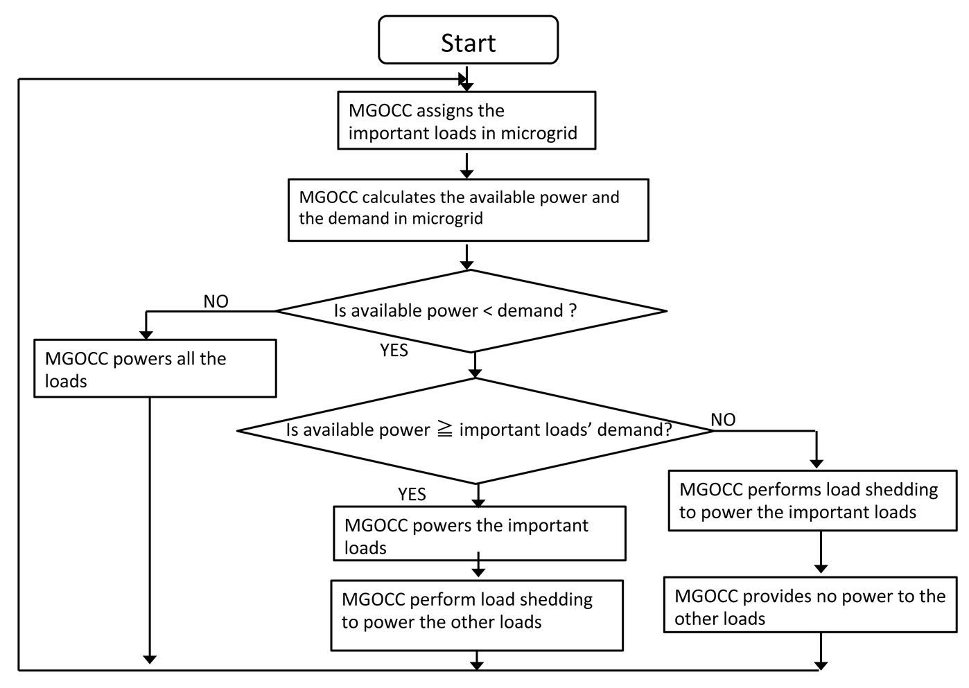
The proposed load shedding scheme is described as a flowchart in Figure 3. In Figure 3, there are two priorities of loads: important loads and other loads. This flowchart illustrates the decision-making flow of the MGOCC agent after collecting all necessary information from the other agents. First, MGOCC assigns which loads are the important loads in the situation, then calculates the available power and the demands from the loads in the microgrid. If the total demand is greater than the total available power, then MGOCC compares the available power with the total important load demands. If the available power is enough to power the important loads, then MGOCC powers all the important loads and then allocates the remaining power to the other loads, if necessary, with an existing load shedding method. If the available power is not enough to power the important loads, we apply an existing load shedding to share the available power among the important loads and allocate no power to the other loads. In this paper, we focus on two existing well-known division methods, which are proportional division and Talmud rule-based division. MGOCC can choose the appropriate division rule based on its operational policies.
In Equation (1), ld represents the vector of load demands and N represents the number of loads. Pa is the available power in Equation (2). Equation (3) is the fundamental condition of a power shortage situation.
In Equation (4), la* is the vector that represents the allocated power to each load. As Equation (5) represents, the sum of allocated power does not exceed the available power, Pa.
The solution vector is ls*, as shown in Equation (6). ls* represents the amount of power loads shed in each load. ls* is calculated as shown in Equation (7). Equation (8) represents the function, alloc(ld, Pa), that returns la*.
The existing resource allocation rules are described as follows: Algorithm 1 represents proportional division, and Algorithm 2 represents Talmud rule-based power allocation. The characteristic of proportional division is that the demand satisfaction rates of each load become exactly the same among all the loads. The Talmud rule-based method allocates resource based on the perspective of the Talmud literature [27]. In our proposal, alloc() calculates the allocated power vector, la*, using Algorithm 1 or Algorithm 2. The microgrid operator can choose one of them as a fair division function.
| Algorithm 1 Proportional division-based power allocation. | |
| 1: | ld ⇐ (ld1, ld2, ld3, …, ldN) |
| 2: | D ⇐ ld1 + ld2 + ld3+, …,+ldN |
| 3: | Pa ⇐ available power |
| 4: | for i = 1 to N do |
| 5: | la*i ⇐ Pa ÷ D × ldi |
| 6: | end for |
| Require: la* is the vector of allocated power as described in Equations (4) and (5) | |
| Algorithm 2 Talmud rule-based power allocation. | |
| Require: talmud(ld, availablepower) return la* | |
| Require: ld1 ≤ ld2 ≤ ld3 ≤, …, ≤ ldN in the order of the load demands | |
| 1: | ld ⇐ (ld1, ld2, ld3, …, ldN) |
| 2: | D ⇐ ld1 + ld2 + ld3+, …,+ldN |
| 3: | Pa ⇐ available power |
| 4: | if Pa ≤ ld1 ÷ 2 × N then |
| 5: | for i = 1 to N do |
| 6: | la*i ⇐ Pa ÷ N |
| 7: | end for |
| 8: | else if D − ld1 ÷ 2 × N ≤ Pa then |
| 9: | for i = 1 to N do |
| 10: | la*i ⇐ ldi − (ld1 + ld2+, …, +ldN − Pa) |
| 11: | end for |
| 12: | else if ld1 ÷ 2 × N ≤ Pa ≤ D − ld1 ÷ 2 × N then |
| 13: | la*1 ⇐ ld1 ÷ 2 |
| 14: | talmud(ld2,…,N, Pa − ld1 ÷ 2) |
| 15: | end if |
| Require: la* is the vector of allocated power, as described in Equations (4) and (5) | |
Existing priority-based load shedding methods and proposed priority-based load shedding are described in Algorithms 3 and 4, respectively. Algorithm 3 is utilized in a reliability evaluation of priority-based load restoration and load shedding [31,32]. In Algorithm 3, the suffix of the load demand is the priority of the load demands. In the existing algorithm, the overlap of priority among load demands is not allowed. The existing algorithm is allocating remaining power from the top priority to lower priorities in a greedy manner.
| Algorithm 3 Existing priority-based load shedding algorithm. | |
| 1: | ld ⇐ (ld1, ld2, ld3, …, ldN) |
| Require: ID of ld, 1..N is the priority of loads | |
| 2: | Pa ⇐ available power |
| 3: | for i = 1 to N do |
| 4: | if Pa ≥ ld*i then |
| 5: | la*i ⇐ ldi |
| 6: | Pa ⇐ Pa − ldi |
| 7: | else |
| 8: | la*i ⇐ Pa |
| 9: | end if |
| 10: | end for |
| 11: | ls* ⇐ ld − la* |
| Require: la* is the vector of allocated power, as described in Equations (4) and (5) | |
| Algorithm 4 Proposed priority-based load shedding algorithm. | |
| 1: | ld ⇐ (ld1, ld2, ld3, …, ldN) |
| 2: | ldGroupi ⇐ arbitrary set of load demands |
| Require: ld = ldGroup1 ∪ ldGroup2 ∪ … ∪ ldGroupM | |
| Require: ID of ldGroup, 1..N is the priority of loads | |
| 3: | Pa ⇐ available power |
| 4: | ldGroup ⇐ (ldGroup1, ldGroup2, …, ldGroupM) |
| 5: | for i = 1 to M do |
| 6: | if totalDemand(ldGroupi) ≤ Pa then |
| 7: | la*i ⇐ ldGroupi |
| 8: | Pa ⇐ Pa − totalDemand(ldGroupi) |
| 9: | else if Pa ≠ 0 then |
| 10: | la*i ⇐ alloc(ldGroupi, Pa) |
| 11: | Pa ⇐ 0 |
| 12: | end if |
| 13: | end for |
| 14: | la* ⇐ la*1 ∪ la *2 ∪ … ∪ la*M |
| 15: | ls* ⇐ ld − la* |
| Require: la* is the vector of allocated power, as described in Equations (4) and (5) | |
In a real microgrid, there are a number of loads, and it is not practical to decide every single load's priority individually. Our proposed load shedding scheme is described in Algorithm 4. The proposed scheme allows the overlap of priority among load demands, by introducing an existing resource allocation function in the case of a power shortage among the load demand group with the same priority. In Algorithm 4, the suffix of the load demand group is the priority of the load demands. The alloc(ldGroupi, Pa) returns allocated power vector la*i using Algorithm 1 or Algorithm 2. The algorithm is chosen based on the microgrid operational policies. Our priority-based load shedding is the combination of priority-based allocation and fairness-oriented allocation, enabling priority-based allocation with fairness in the group with the same priority.
3.2. Agent-Based Hierarchical Operation of Microgrid
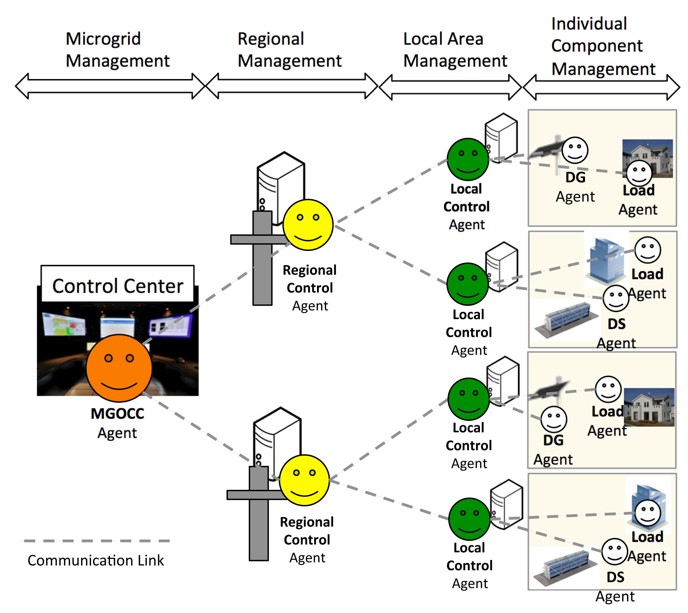
The proposed architecture is shown in Figure 4. There are six roles of agents in the proposed architecture, namely microgrid operation and control center (MGOCC) agent, regional control (RC) agent, local control (LC) agent, load agent, distributed generator (DG) agent and distributed storage (DS) agent. The MGOCC agent collects information from the RC agents to make a decision about the operation and control. Load agents, DG agents and DS agents collect information of each component and control it as commanded by the LC agents. The information aggregation process in the LC agent is shown in Algorithm 5, where ld is the vector of load demands and pa is the vector of power supplies in the local area. LC agents receive messages from the load, DG, DS agents about the components in the microgrid and pass the localDemand and localPowerAvailable to the upper RC agents. The information aggregation process in the RC agent is shown in Algorithm 6, where localDemand is the vector or local demands reported by the LC agents and localPowerAvailable is the vector of power available reported by the LC agents. The RC agents receive messages from the LC agents to aggregate the information and pass regionalDemand and regionalPowerAvailable onto the MGOCC agent. The information aggregation in the LC and RC agents enable our proposed architecture to mitigate the calculation concentration in the MGOCC agents, especially when the number of components in the microgrid increases.
| Algorithm 5 The information aggregation process in the local control agent. | |
| 1: | ld ⇐ (ld1, ld2, ld3, …, ldN) |
| 2: | pa ⇐ (pa1, pa2, pa3, …, paM) |
| 3: | localDemand ⇐ 0 |
| 4: | localPowerAvailable ⇐ 0 |
| 5: | for i = 1 to N do |
| 6: | localDemand ⇐ localDemand + ldi |
| 7: | end for |
| 8: | for i = 1 to M do |
| 9: | localPowerAvailable ⇐ localPowerAvailable + pai |
| 10: | end for |
| Algorithm 6 The information aggregation process in the regional control agent. | |
| 1: | localDemand ⇐ (ld1, ld2, ld3, …, ldN) |
| 2: | localPowerAvailable ⇐ (pa1, pa2, pa3, …, paM) |
| 3: | regionalDemand ⇐ 0 |
| 4: | regionalPowerAvailable ⇐ 0 |
| 5: | for i = 1 to N do |
| 6: | regionalDemand ⇐ regionalDemand + ldi |
| 7: | end for |
| 8: | for i = 1 to M do |
| 9: | regionalPowerAvailable ⇐ regionalPowerAvailable + pai |
| 10: | end for |
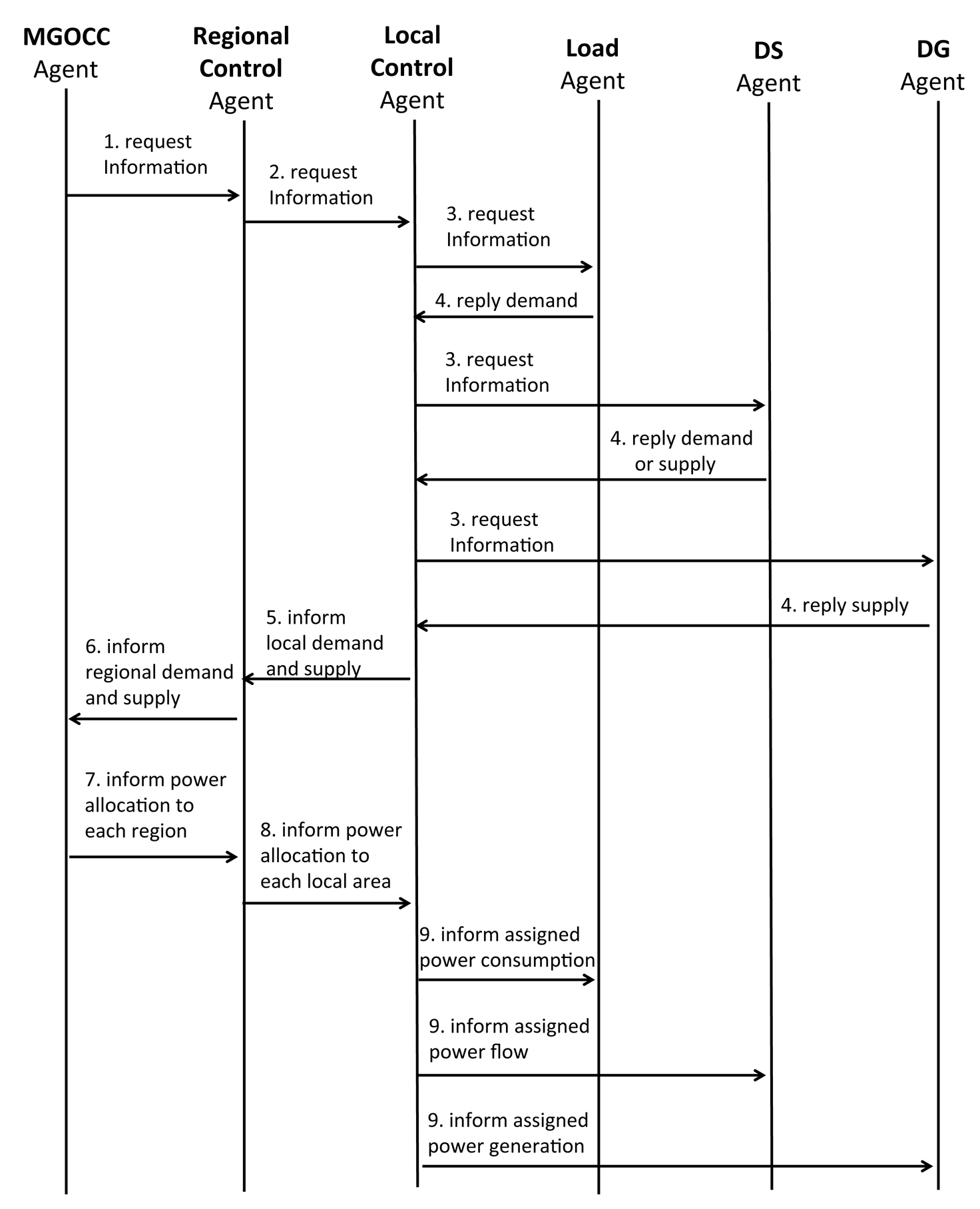
The message flow among agents in the proposed architecture is shown in Figure 5. First, MGOCC requests the necessary information from the RC agents. After sending the request, the RC agents request the necessary information from the LC agents. The load agent sends back its demand power. The DS agent sends back its charged power, and the DG agent sends back the amount of power generated by the generator to the LC agent. After receiving this information, the LC agents aggregate the information and send it to the RC agents. After the RC agents receive the information from the LC agents, the RC agents aggregate the information and send it to MGOCC agent. After receiving all the information, the MGOCC agent makes a decision to allocate power to each region managed by the RC agents. When the decision is made, MGOCC informs the RC agents about the assigned power. The RC agents parse the power allocation information from the MGOCC agent based on the employed load shedding method and derive the power allocation to each local area managed by the LC agents. After parsing, the RC agents send power allocation information to the LC agents. The LC agents parse the power allocation information from the RC agent and derive the power allocation to each component. After the parsing, the LC agents send the power allocation information to the load agents, the DS agents and the DG agents.
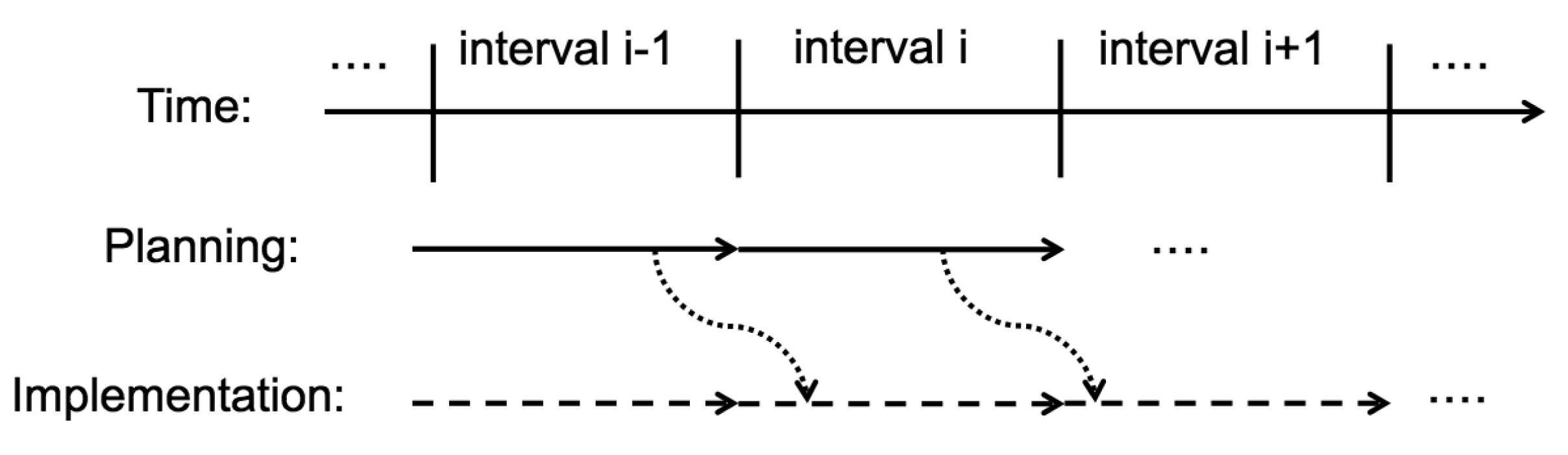
Information gathering, decision-making and the implementation of the decision are all done in the message flow of Figure 5, which is counted as one interval of the microgrid operation. The microgrid operation cycle is illustrated in Figure 6. The interval is a time unit of the microgrid operation, and MGOCC plans and implements its operation in each interval. For example, in Interval i, MGOCC plans the next operation, which is implemented in Interval i + 1. The plan is decided based on the current implementation, which is planned in Interval i − 1.
4. Experiment and Evaluation
In order to evaluate the proposed load shedding scheme, we have implemented a multiagent system for simulating a microgrid. The simulator consists of the proposed hierarchical agents. We have used the ADIPS (Agent-based Distributed Information Processing System)/DASH (Distributed Agent System based on Hybrid Architecture) agent and IDEA (Interactive Design Environment for Agent system) to implement this system [33,34].
4.1. Small-Scale Scenario-Based Simulation
This simulation assumes that the microgrid is suddenly forced to switch into island mode, because of a utility grid disturbance, and the power from generators is constantly diminishing, because power generation needs an energy source, e.g., fuel, gas, etc. The employed load shedding method used in our priority-based load shedding scheme is proportional division.
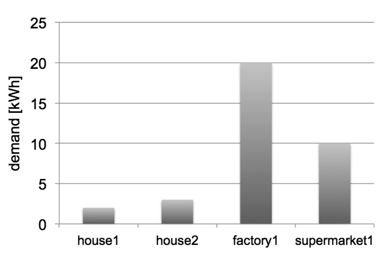
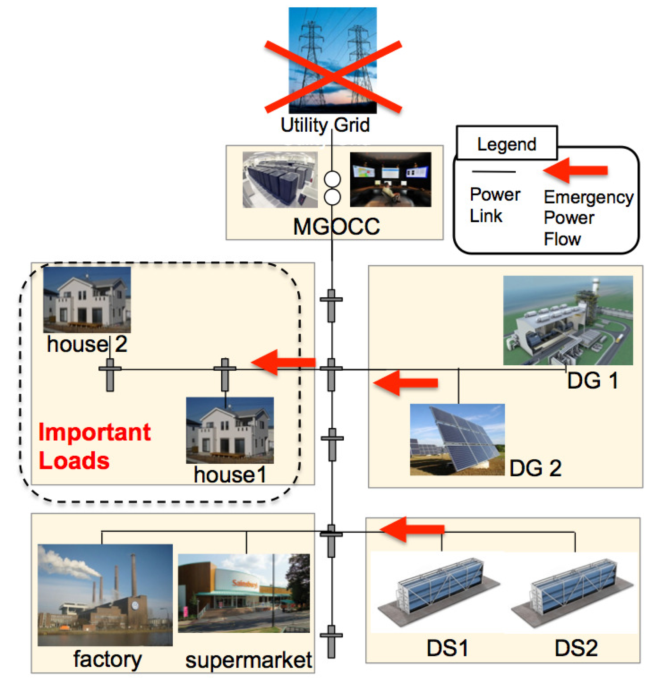
The simulated microgrid in this evaluation is as illustrated in Figure 7. After a utility grid disturbance occurs, the power in the microgrid is primarily allocated to the important loads, in this case, house1 and house2. Power allocation for the supermarket and factory are shed as the power availability in the microgrid decreases. We assume the demand in the microgrid is as shown in Figure 8. The demand of the loads are fixed during this simulation. House1 and house2 are assigned as important loads. The other loads are factory and supermarket.
The loads, house1, house2, factory and supermarket, are managed by load agents. The distributed generators, such as DG1 and DG2 are managed by DG agents. The distributed storage, DS1 and DS2, are managed by DS agents. The MGOCC agent is in the control center and manages individual agents in the microgrid.
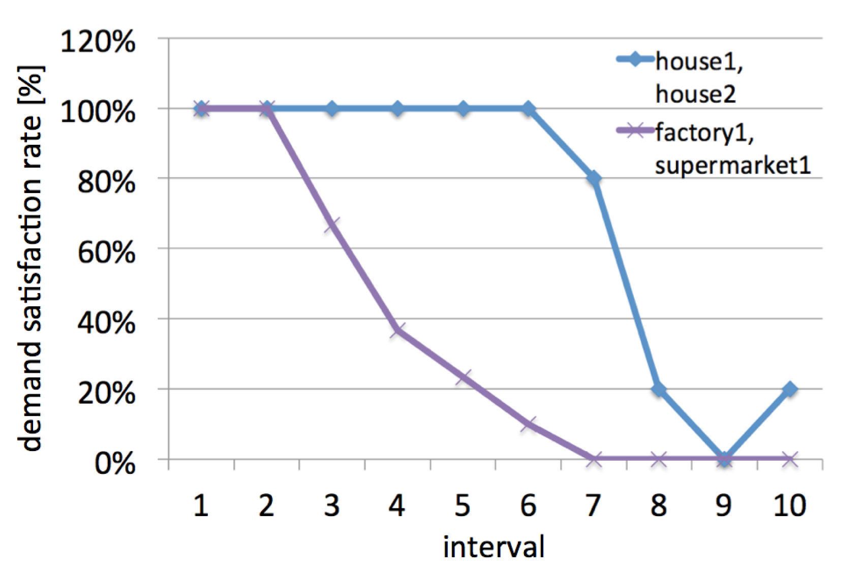
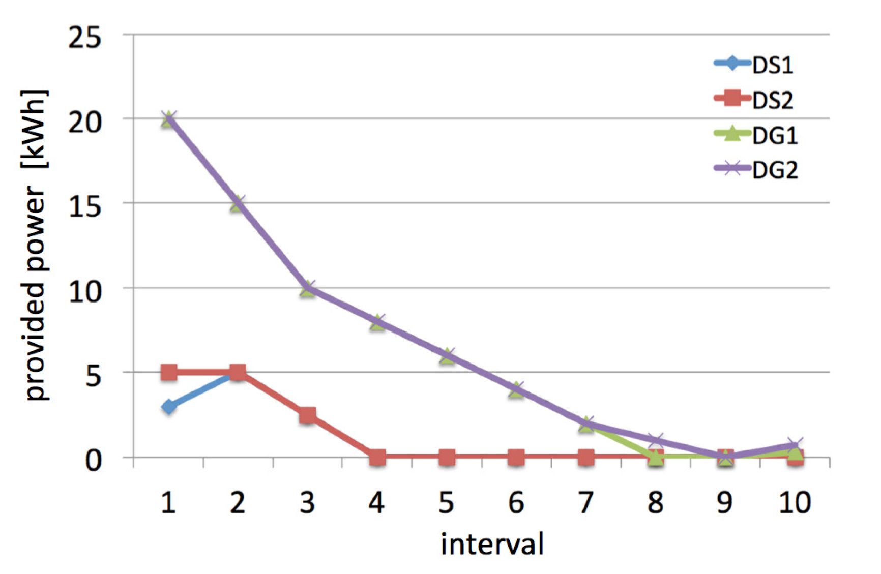
Figure 9 shows the transition of available power provided by DG1, DG2, DS1 and DS2. Figure 10 shows the transition of allocated power to each load. These two figures illustrate the decreasing available power in the microgrid. At Interval 9, there is no available power, but at Interval 10, generators start to provide some power again. From these two figures, it is difficult to see if the proposed load shedding scheme is effective or not. In contrast, Figure 11 clearly illustrates how effective our scheme is. The demand satisfaction rate is a percentile value that indicates the ratio of allocation divided by demand. Since house1 and house2 are both assigned as important loads, these 2 loads get the same demand satisfaction rate. Likewise, factory and supermarket are both not assigned as important loads; therefore, they get the same demand satisfaction rate. As the available power in the microgrid decreases, the demand satisfaction rate of non-important loads decreases. In contrast, the demand satisfaction rate of important loads is kept at 100% until Interval 6. Even when the rate becomes zero at Interval 9, it quickly recovers to 20% by getting the available power provided by generators. According to this figure, the proposed load shedding scheme keeps important loads as long as possible and also allows the resilience to recover as quickly as possible.
4.2. Large-Scale Scenario-Based Simulation
In order to confirm that our load shedding scheme works effectively at a larger scale, we have performed a large-scale scenario-based simulation of a microgrid. The amount of demand and supply used in this simulation are determined by referring to the operational data disclosed by the PJM (Pennsylvania, New Jersey, Maryland) interconnection [35]. In this experiment, the employed load shedding method used in our priority-based load shedding scheme is the Talmudic bankruptcy rule.
This simulation assumes the situation that the microgrid is suddenly forced to switch into island mode because of a utility grid disturbance, and the generators are providing less and less power.
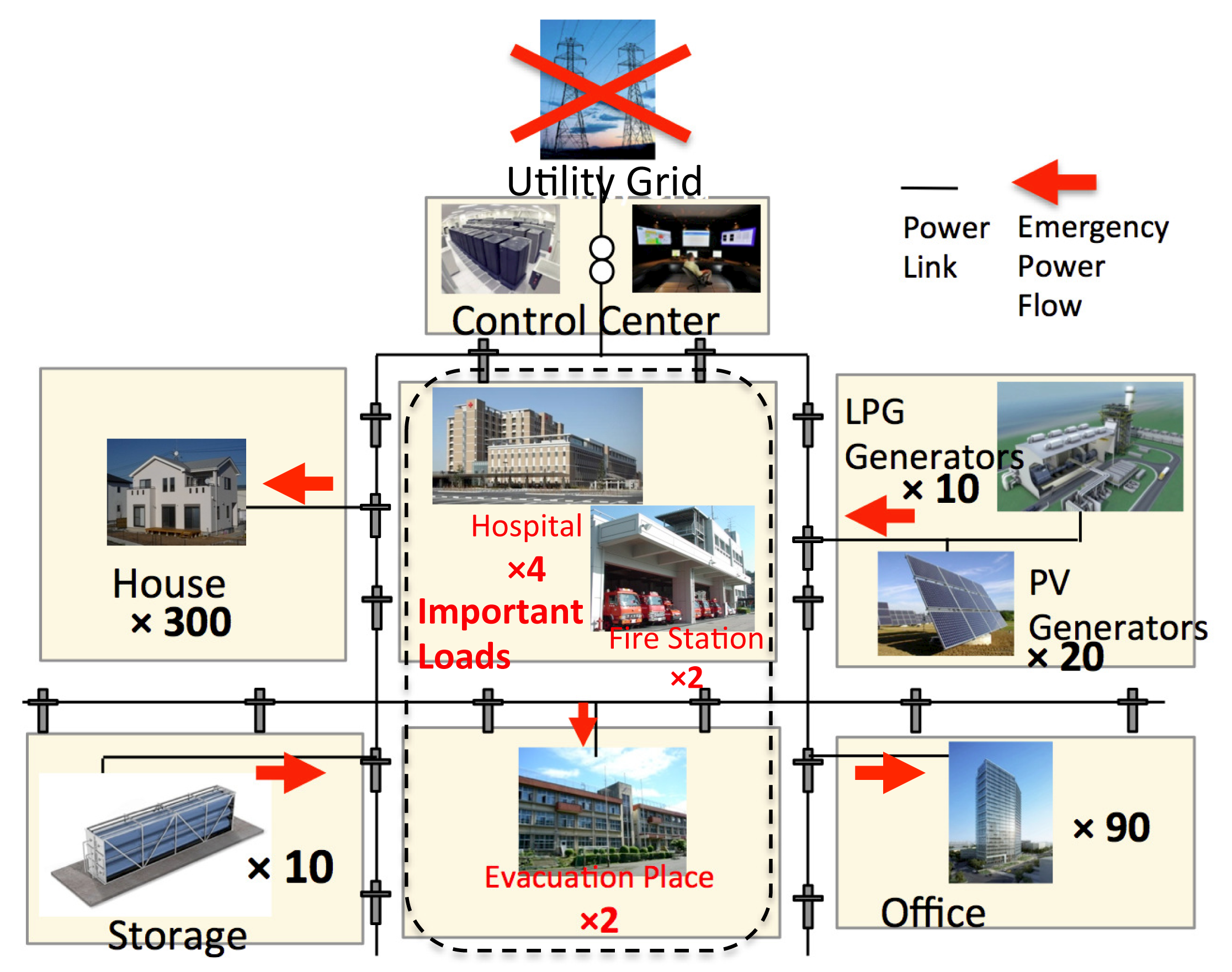
The simulated microgrid in this large-scale scenario is as illustrated in Figure 12. The list of loads is shown in Table 1. There are: 4 hospitals, 2 fire stations, 2 evacuation places, 90 commercial buildings and 300 households. In this simulation, there are 3 groups of loads in the microgrid. The hospitals have the highest priority (4, being the highest). Evacuation places and fire stations have the second highest priority (3). The houses have the next highest priority (2), and the offices have the lowest priority (1).
The rest of the loads, commercial buildings and households have the least priority (3rd load group) in this simulation.
There are two kinds of distributed generators, which are LPG generators and photovoltaic generators. LPG generators generate power by burning natural gas; thus, they are unable to generate power after the gas runs out. Photovoltaic (PV) generators generate power by converting sun light into power; thus, they provide less and less power as the sun sets. There are 20 PV generators and 10 LPG generators in this simulated microgrid.
After a utility grid disturbance occurs, by using our proposed load shedding scheme, the power in the microgrid is primarily allocated to the 1st load group, in this case hospitals. The remaining power is allocated to the 2nd load group, fire stations and evacuation places, and then, the remaining power is allocated to the 3rd and 4th important load groups.
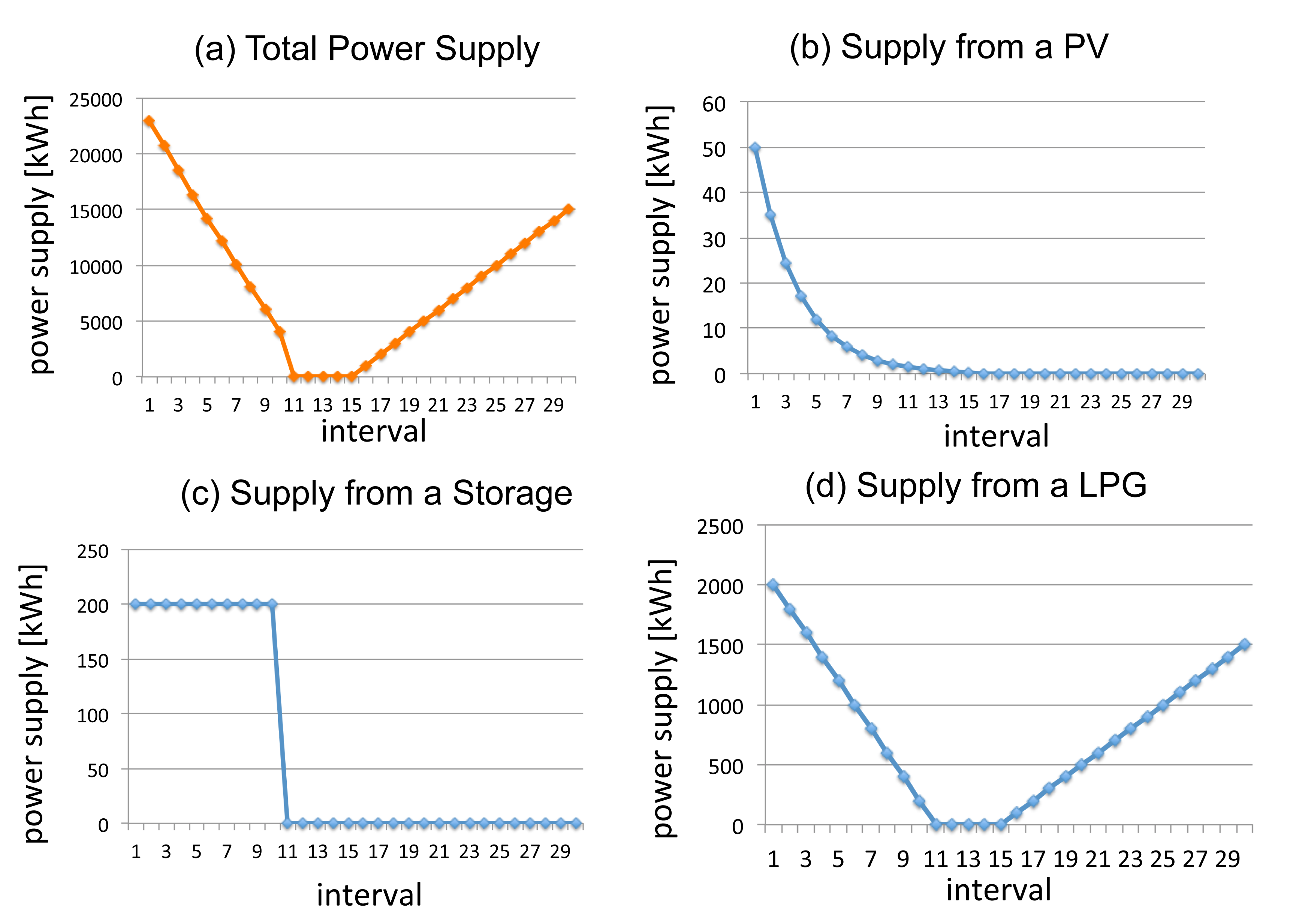
The demand of the microgrid is shown in Table 1. The demand of the loads are fixed during this simulation. Figure 13 shows the transition of the power supply from DGs and DSs. Figure 13a is the total power supply in each interval, which is the sum of all power supplies shown as Figure 13b–d. Figure 13b shows the transition of available power generated by each PV, Figure 13c shows the supply transition from each storage, and Figure 13d shows the transition of supply from each LPG generator.
During the experiment, the number of LPG generators decreases. After a few intervals, about 15 generators have stopped due to a lack of gas. The stopped generators starts power generation again after gas becomes available. The PV generators provide less power as the sun sets. Since the microgrid is in the power shortage situation, storage is discharged continuously during this simulation.
Figure 14 illustrates how effective our scheme is. Figure 15 shows the simulation result without the priority of loads (the existing scheme). Demand satisfaction is a percentile value, which indicates the ratio of allocation divided by demand. Since hospitals are assigned as the most important group of loads, the demand satisfaction rate of hospitals remains at 100%, because of the proposed load shedding scheme. Fire stations and evacuation places, the second important loads, keep at 100% longer than the houses. As the available power in the microgrid decreases, first the demand satisfaction rate of offices goes down. When the demand satisfaction rate of office reaches 0%, house's satisfaction rate starts to decrease.
The result shows that our load shedding scheme allows the microgrid to ensure the power for important loads at a larger scale. In this simulation, hospitals are kept at 100% for the longest. They remain at 100% as long as possible and recover to 100% as soon as power becomes available. According to this, the proposed load shedding scheme keeps important loads as long as possible and recovers as quickly as possible.
5. Demonstration Experiment
In order to evaluate the proposed load shedding scheme and hierarchical multiagent architecture, we have designed and developed an environment for the demonstration of experiments dealing with actual power. It is a physical, miniature microgrid that is used for the evaluation. In this experiment, the employed load shedding method used in our priority-based load shedding scheme is proportional division.
The main objective of this demonstration experiment is to confirm that the proposed method is effective in a microgrid despite physical difficulties, such as the uncertainty of power generation from renewable generators, the inaccuracy in measuring power consumption, etc. In order to develop such an environment, we have used LEGO Mindstorms [36].
Individual agents are implemented in a LEGO Mindstorms NXT intelligent brick [37] as Java programs. We have employed a LeJOS operating system [38] on an NXT intelligent bricks. The communication among NXTs are done via Bluetooth. In our miniature microgrid, one local area managed by an LC agent is implemented in one NXT intelligent brick. If there are load agents, DS agents or DG agents in one local area, one NXT intelligent brick runs all four agents. The RC agent is implemented in one NXT intelligent brick. The MGOCC agent is also implemented in one NXT intelligent brick.
We prepared 2 kinds of loads using LEGO Mindstorms' kit. One of them is an NXT servo motor. NXT is capable of controlling motors [39], which consume power provided from NXT. The power consumption is controllable by adjusting the speed of the motor rotation. Another load we prepared is LED (Light-Emitting Diode) light, which came with a renewable energy add-on set [40]. Having these 2 kinds of loads enables us to demonstrate big and small loads controlled by agents in NXT intelligent bricks.
Individual NXTs have built-in batteries. NXTs can sense the output voltage to estimate the charged power in the batteries. The batteries in NXTs are used as distributed storage in our miniature microgrid.
Our miniature microgrid has renewable energy generators available from the renewable energy add-on set [40]. The distributed generators are managed by DG agents. DG agents sense the power generation and report the power supply to the local control agent in each interval.
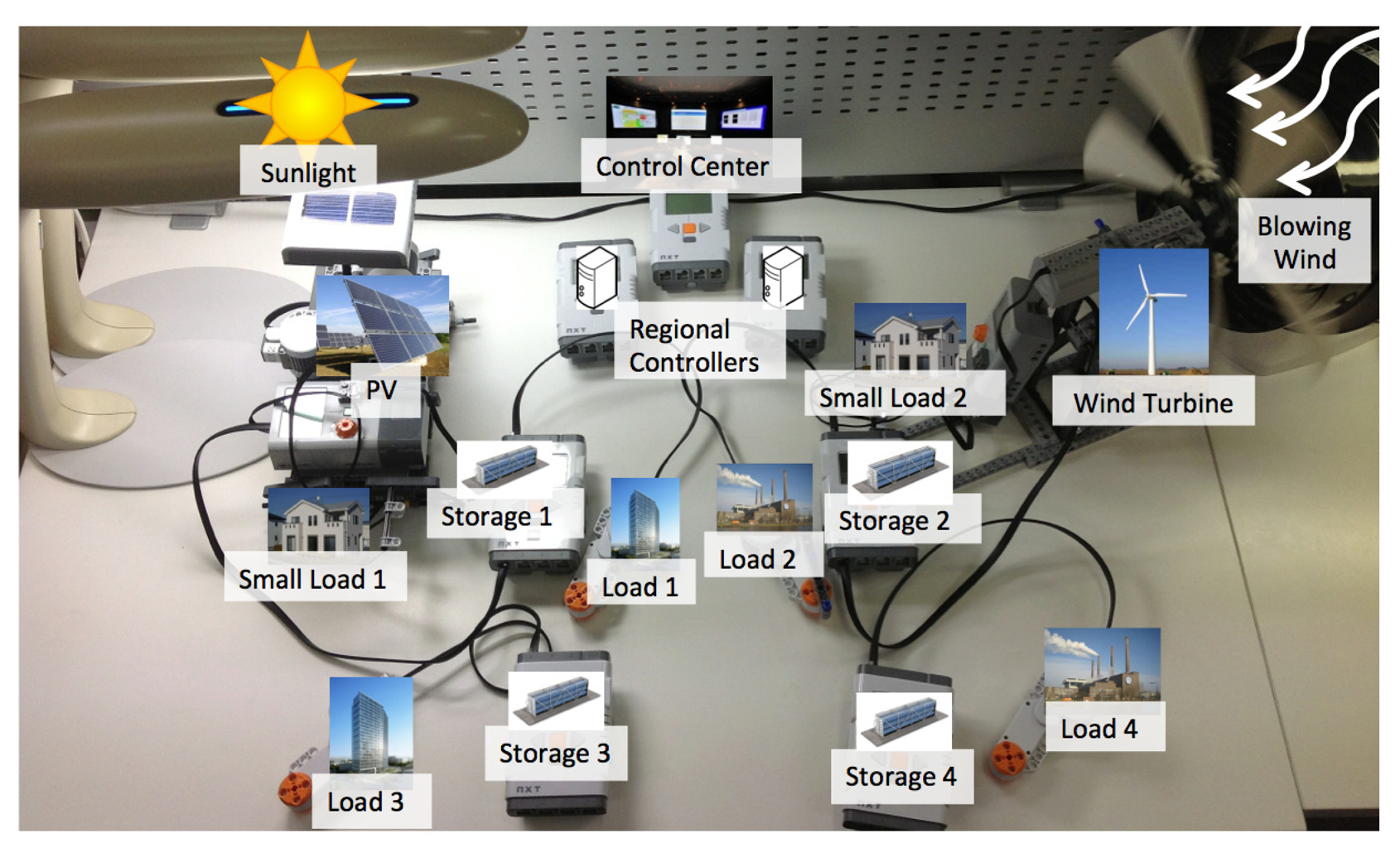
The model of the demonstrated microgrid in this experiment is shown in Figure 16. There are 4 areas in the demonstrated microgrid. All of the areas have DSs that provide power for each area. Area 1 and Area 2 have PVs (photovoltaic) and wind turbines, which provide power for each area, respectively. Small Load 1 and Small Load 2 are the important loads in this model, which means the power for these two loads needs to be preserved even when other loads' power is shed.
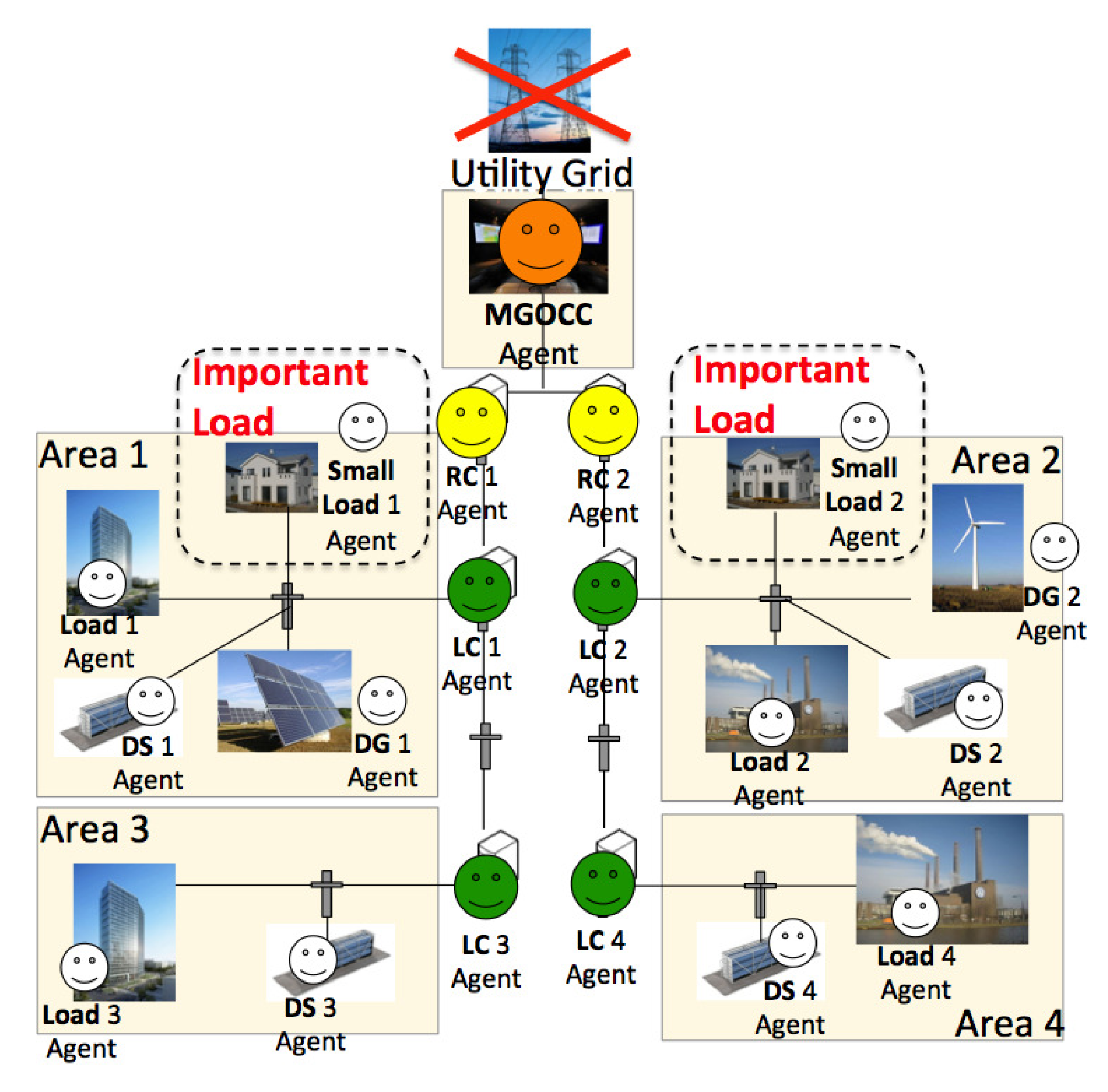
The agent configuration of the demonstrated microgrid is shown in Figure 17. Four LC (local control) agents manage individual areas. DG, DS and load agents control their components in each area. The RC (regional control) 1 Agent manages the LC 1 agent and the LC 3 agent. The RC 2 agent manages the LC 2 agent and the LC 4 agent. The MGOCC (microgrid operation and control center) agent manages the RC 1 agent and the RC 2 agent.
The overview of the miniature microgrid for demonstrating the model is shown in Figure 18. Each area is implemented by an NXT intelligent brick [37], and it controls the components in the area.
The LC 1 agent manages the Load 1 agent, the Small Load 1 agent and the DG 1 agent. The Load 1 agent manages a motor [39], which consumes power in Area 1. The DS 1 agent manages a battery build in an NXT intelligent brick, which supplies power in Area 1. The DG 1 agent manages a PV, which generates power by converting sunlight into electricity. The DG 1 agent senses the power generation using an energy meter [40]. The Small Load 1 agent manages an LED light, which consumes a small amount of power in the area.
The LC 2 agent manages the Load 2 agent, the Small Load 2 agent and the DG 2 agent. The Load 2 agent manages a motor [39], which consumes power in Area 2. The DS 2 agent manages a battery build in an NXT intelligent brick, which supplies power in Area 2. The DG 2 agent manages a wind turbine, which generates power by converting force from the wind into electricity. The DG 2 agent senses power generation using an energy meter [40]. The Small Load 2 agent manages an LED light, which consumes small amount of power in the area.
The LC 3 agent manages the Load 3 agent and the DS 3 agent. The Load 3 agent manages a motor, which consumes power in the area. The DS 3 agent manages a battery built in an NXT intelligent brick. Likewise, the LC 4 agent manages the Load 4 agent and the DS 4 agent, managing a motor and a built-in battery in an NXT intelligent brick, respectively.
The RC 1 agent manages the LC 1 agent and the LC 3 agent. The RC 1 agent aggregates the information reported from the LC 1 agent and the LC 3 agent and passes the information on to the MGOCC agent. Likewise, the RC 2 agent manages the LC 2 agent and the LC 4 agent. The RC 2 agent aggregates the information reported from the LC 2 agent and the LC 4 agent and passes the information on to the MGOCC agent. After MGOCC makes an operational decision, the MGOCC agent sends a command to the RC 1 agent and the RC 2 agent allocating power to each region based on the proposed load shedding scheme. The RC 1 agent and the RC 2 agent parse the command from MGOCC and allocate power to each area by using the proposed load shedding scheme. The LC 1 agent, LC 2 agent, LC 3 agent and LC 4 agent allocate power to each load by using the proposed load shedding method.
The scenario of this experiment is as follows: because of a disaster (e.g., earthquake), the microgrid is forced to switch into island mode, and the power in DS starts to run out as time passes. One interval is 15 min, as investigated and determined in the existing research [11]. There are 12 intervals in this experiment, which means it takes 3 h to finish the experiment. Figure 19 shows the weather data, which is used for setting the wind's strength and the light's strength of the experimental environment. The data in Figure 20 shows the transition of the power supply from wind turbine and PV, which are following the transition of the weather data in Figure 19.
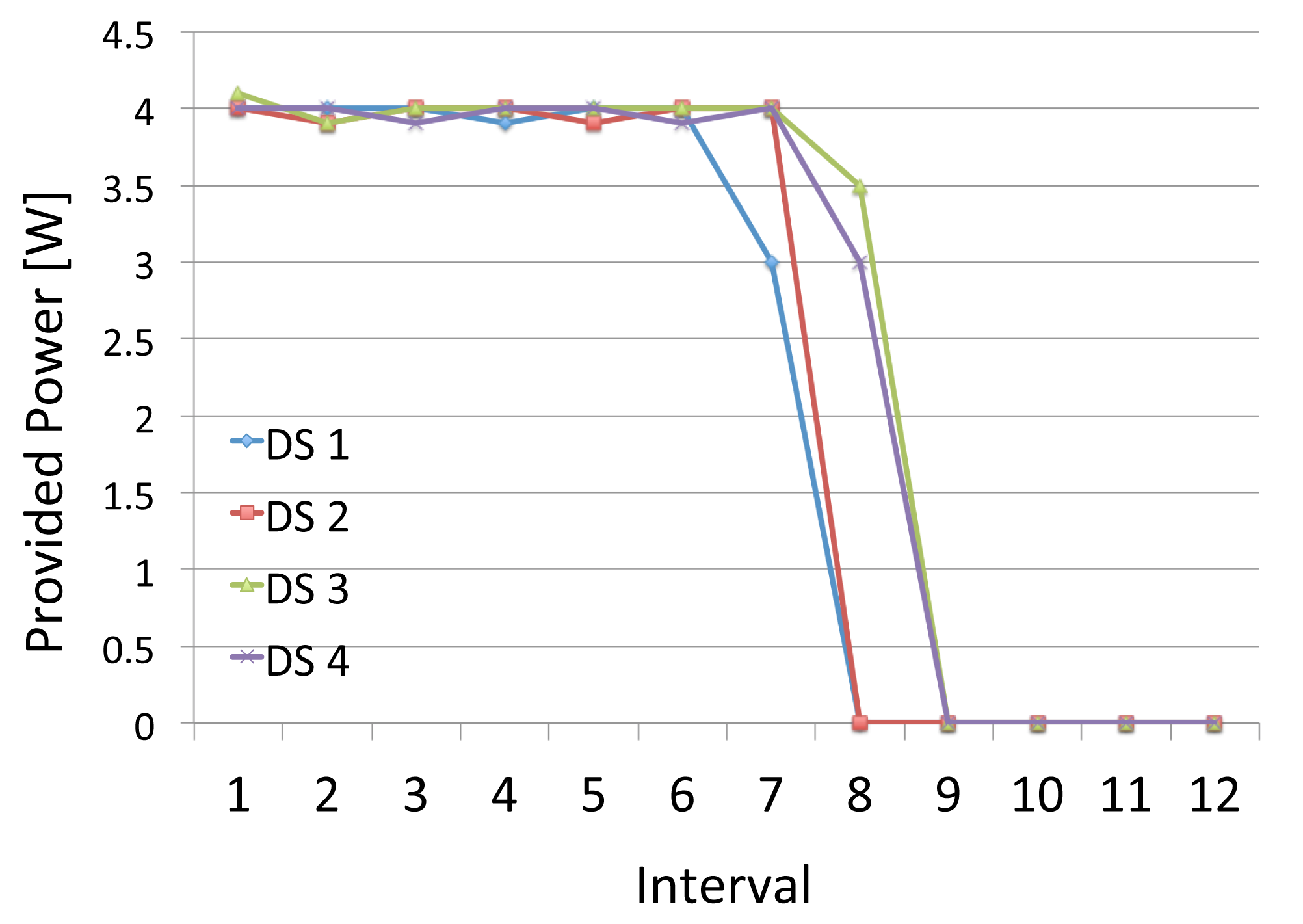
Figure 21 shows the transition of the power supply from distributed storage. The power supply from the storage is determined based on the charged power in individual storage. The power supply transition of all DSs are planned as the same; however, due to the gap between the sensed charged power and actual charged power, DS1's and DS2's power supplies go down earlier than planned.
Figure 22 shows the demand satisfaction rate of each load in the miniature microgrid. Despite DS1's and DS2's unexpected power supply shortages, the important loads, such as Small Load 1 and Small Load 2, remain at 100% because of the effect of our load shedding scheme.
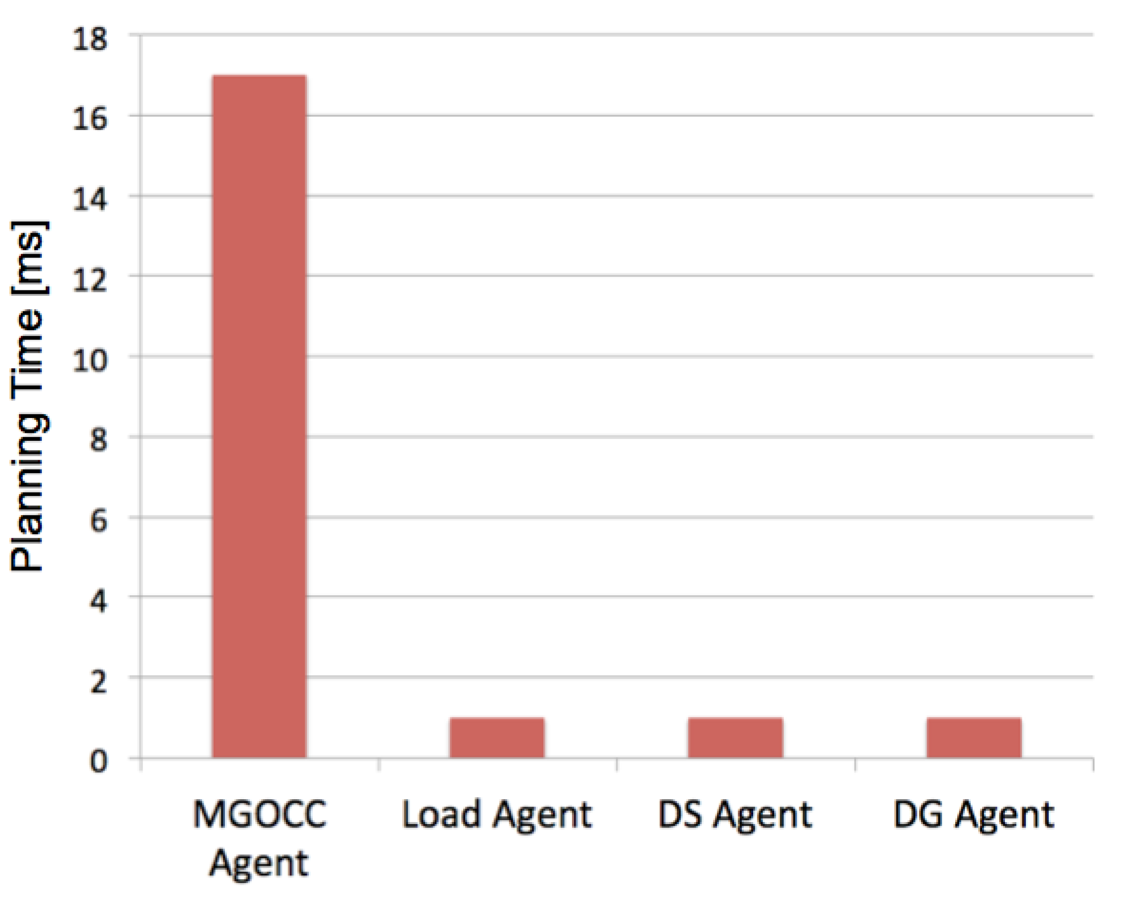
Figures 23 and 24 show the average calculation time. The “proposed multiagent architecture” is as explained in Figure 4. The “existing multiagent architecture” is without the RC agents and the LC agents. In this case, the MGOCC agent directly administrates the load agent, DS agent and DG agent. The existing architecture is employed in several approaches [11–15]. The data shows a 41% decrease in the computational load on the MGOCC. This is due to the calculation done by the RC and LC agents and the hierarchical structure.
The results from this experiment show the effectiveness of our proposed load shedding scheme and hierarchical multiagent architecture, despite the physical difficulties.
6. Conclusions and Future Work
The purpose of our research is to realize resilient power grid operation during a utility grid disturbance. This paper focuses on microgrids, which are a small-scale power supply network designed to provide power for small communities.
There are several research papers on the autonomous operation of a microgrid based on multiagent systems, and having analyzed them, we found two main problems:
P1 Ensuring the power for important loads is difficult in islanded microgrid using the existing operational scheme;
P2 The concentrated computational cost in the MGOCC agent.
We have proposed a new management method with two solutions, which are summarized as follows:
S1 Load shedding considering the priority of loads;
S2 Agent-based hierarchical operation of the microgrid.
We have developed two simulation environments, which are a software-based microgrid simulator and a physical demonstration environment. We have evaluated our solutions in a series of experiments, and it has been confirmed that our method enables a microgrid to sustain power for important loads as long as possible and to recover as quickly as possible. The result of the demonstration shows the effectiveness of the proposed load shedding scheme, as well as the hierarchical multiagent architecture.
In future work, we are considering focusing on the usage of an electric vehicle, cooperation between the microgrid operation center and the Home Energy Management System (HEMS) built-in smart home environment, etc.
Acknowledgments
A part of this work is supported by Bilateral Joint Research Projects/Seminars of Japan Society for the Promotion of Science (JSPS).
Conflicts of Interest
The authors declare no conflict of interest.
References
- Pararas-Carayannis, G. The Great Tsunami of March 11, 2011 in Japan—Analysis of Source Mechanism and Tsunamigenic Efficiency. Proceedings of the IEEE/OES OCEANS 2011, Waikoloa, HI, USA, 19–22 September 2011; pp. 1–10.
- Adachi, T. The Restoration of Telecom Power Damages by the Great East Japan Earthquake. Proceedings of the IEEE 33rd International Telecommunications Energy Conference (INTELEC), Amsterdam, The Netherlands, 9–13 October 2011; pp. 1–5.
- Kezunovic, M. Smart Fault Location for Smart Grids. IEEE Trans. Smart Grid 2011, 2, 11–22. [Google Scholar]
- Xu, Y.; Liu, W. Novel multiagent based load restoration algorithm for microgrids. IEEE Trans. Smart Grid 2011, 2, 152–161. [Google Scholar]
- Nguyen, C.P.; Flueck, A.J. Agent based restoration with distributed energy storage support in smart grids. IEEE Trans. Smart Grid 2012, 3, 1029–1038. [Google Scholar]
- Kim, D.-M.; Kim, J.-O. Design of emergency demand response program using analytic hierarchy process. IEEE Trans. Smart Grid 2012, 3, 635–644. [Google Scholar]
- Wang, Y.; Pordanjani, I.R.; Xu, W. An event-driven demand response scheme for power system security enhancement. IEEE Trans. Smart Grid 2011, 2, 23–29. [Google Scholar]
- Kim, H.-M.; Kinoshita, T.; Lim, Y. Talmudic approach to load shedding of islanded microgrid operation based on multiagent system. J. Electr. Eng. Technol. 2011, 6, 284–292. [Google Scholar]
- Kim, H.-M.; Lim, Y.; Kinoshita, T. An intelligent multiagent system for autonomous microgrid operation. Energies 2012, 5, 3347–3362. [Google Scholar]
- Concordia, C.; Fink, L.H.; Poullikkas, G. Load shedding on an isolated system. IEEE Trans. Power Syst. 1995, 10, 1467–1472. [Google Scholar]
- Dimeas, A.L.; Hatziargyriou, N.D. Operation of a multiagent system for microgrid control. IEEE Trans. Power Syst. 2005, 20, 1447–1455. [Google Scholar]
- Dimeas, A.L.; Hatziargyriou, N.D. A Multi-Agent System for Microgrids. Proceedings of the IEEE Power Engineering Society General Meeting, Denver, CO, USA, 6–10 June 2004; pp. 55–58.
- Jian, Z.; Qian, A.; Chuanwen, J.; Xingang, W.; Zhanghua, Z.; Chenghong, G. The Application of Multi Agent System in Microgrid coordination control. Proceedings of the 1st International Conference on Sustainable Power Generation and Supply (SUPERGEN 2009), Nanjing, China, 6–7 April 2009; pp. 1–6.
- Kuo, M.-T.; Lu, S.-D. Design and implementation of real-time intelligent control and structure based on multi-agent systems in microgrids. Energies 2013, 6, 6045–6059. [Google Scholar]
- Kyriakarakos, G.; Piromalis, D.D.; Dounis, A.I.; Arvanitis, K.G.; Papadakis, G. Intelligent demand side energy management system for autonomous polygeneration microgrids. Appl. Energy 2013, 103, 39–51. [Google Scholar]
- Li, J.; Su, J.; Yang, X.; Zhao, T. Study on Microgrid Operation Control and Black Start. Proceedings of the 4th International Conference on Electric Utility Deregulation and Restructuring and Power Technologies (DRPT), Weihai, China, 6–9 July 2011; pp. 1652–1655.
- Implementation Plan of Rolling Blackout on and after Tue. March 15 2011. Available online: http://www.tepco.co.jp/en/press/corp-com/release/11031406-e.html (accessed on 10 February 2014).
- Tokyo Electric Power Company (TEPCO). Available online: http://www.tepco.co.jp/en/index-e.html (accessed on 10 February 2014).
- Wooldridge, M. An Introduction to Multiagent Systems; John Wiley and Sons Publication: Chichester, UK, 2009. [Google Scholar]
- Dimeas, A.L.; Hatiziargyriou, N.D. Agent Based Control for Microgrids. Proceedings of the IEEE 2007 Power Engineering Society General Meeting, Tampa, FL, USA, 24–28 June 2007; pp. 1–5.
- Logenthiran, T.; Srinivasan, D.; Khambadkone, A.M.; Aung, H.N. Multiagent System for Real-Time Operation of a Microgrid in Real-Time Digital Simulator. IEEE Trans. Smart Grid 2012, 3, 925–933. [Google Scholar]
- Vytelingum, P.; Voice, T.D.; Ramchurn, S.D.; Rogers, A.; Jennings, N.R. Intelligent Agents for the Smart Grid. Proceedings of the 9th International Conference on Autonomous Agents and Multiagent Systems (AAMAS 2010), Toronto, Canada, 9–14 May 2010; pp. 1649–1650.
- Shao, D.; We, Q.; Nie, T. A Multi-Agent Control Strategy in Microgrid Island Mode. Proceedings of the 6th International Forum on Strategic Technology, Harbin, China, 22–24 August 2011; pp. 429–432.
- Arai, J.; Yamazaki, S.; Ishikawa, M.; Ito, T. Study on a New Power Control of Distributed Generation in an Isolated Microgrid. Proceedings of the IEEE Power & Energy Society General Meeting (PES '09), Calgary, AB, Canada, 26–30 July 2009; pp. 1–6.
- Logenthiran, T.; Srinivasan, D.; Khambadkone, A.M.; Aung, H.N. Scalable Multi-Agent System (MAS) for Operation of a Microgrid in Islanded Mode. Proceedings of the 2010 Joint International Conference on Power Electronics, Drives and Energy Systems (PEDES) & 2010 Power India, New Delhi, India, 20–23 December 2010; pp. 1–6.
- Ramchurn, S.D.; Vytelingum, P.; Rogers, A.; Jennings, N. Agent-Based Control for Decentralised Demand Side Management in the Smart Grid. Proceedings of the 10th International Conference on Autonomous Agents and Multiagent Systems (AAMAS 2011), Taipei, Taiwan, 2–6 May 2011; pp. 5–12.
- Aumann, R.J.; Michael, M. Game theoretic analysis of a bankruptcy problem from the Talmud. J. Econ. Theory 1985, 36, 195–213. [Google Scholar]
- Rose, H.; Rogers, A.; Gerding, E.H. A Scoring Rule-Based Mechanism for Aggregate Demand Prediction in the Smart Grid. Proceedings of the 11th International Conference on Autonomous Agents and Multiagent Systems (AAMAS 2012), Valencia, Spain, 4–8 June 2012; pp. 661–668.
- Motamedi, A.; Zareipour, H.; Rosehart, W.D. Electricity price and demand forecasting in smart grids. IEEE Trans. Smart Grid 2012, 3, 664–674. [Google Scholar]
- Misra, A.; Schulzrinne, H. Policy-Driven Distributed and Collaborative Demand Response in Multi-Domain Commercial Buildings. Proceedings of the 1st International Conference on Energy-Efficient Computing and Networking, Passau, Germany, 13–15 April 2010; pp. 119–122.
- Kennedy, S.; Marden, M.M. Reliability of Islanded Microgrids with Stochastic Generation and Prioritized Load. Proceedings of the IEEE Bucharest Power Tech Conference, Bucharest, Romania, 28 June–2 July 2009; pp. 1–7.
- Bae, I.-S.; Kim, J.-O. Reliability evaluation of distributed generation based on operation mode. IEEE Trans. Power Syst. 2007, 22, 785–790. [Google Scholar]
- IDEA/DASH Tutorial. Available online: http://www.k.riec.tohoku.ac.jp/idea/index.html (accessed on 10 February 2014).
- Kinoshita, T.; Sugawara, K. ADIPS Framework for Flexible Distributed Systems. Proceedings of the Pacific Rim International Workshop on Multi-Agents (PRIMA98), Singapore, 23 November 1998; pp. 161–175.
- PJM Operational Data. Available online: http://www.pjm.com/markets-and-operations.aspx (accessed on 10 February 2014).
- LEGO Mindstorms. Available online: http://mindstorms.lego.com/en-us/Default.aspx (accessed on 10 February 2014).
- NXT Intelligent Brick—LEGO Shop. Available online: http://shop.lego.com/en-US/NXT-Intelligent-Brick-9841 (accessed on 10 February 2014).
- LEJOS—Java for LEGO Mindstirms. Available online: http://lejos.sourceforge.net/ (accessed on 10 February 2014).
- Interactive Servo Motor—LEGO Shop. Available online: http://shop.lego.com/en-US/Interactive-Servo-Motor-9842 (accessed on 10 February 2014).
- Renewable Energy Add-On Set—LEGO Shop. Available online: http://www.legoeducation.us/eng/product/renewable_energy_add_on_set/2101 (accessed on 10 February 2014).


| Component | Number of Components | Priority | Demand (kWh) |
|---|---|---|---|
| Hospital | 4 | 4 | 400 |
| Evacuation place | 2 | 3 | 120 |
| Fire station | 2 | 3 | 300 |
| House | 300 | 2 | 15 |
| Office | 90 | 1 | 90 |
© 2014 by the authors; licensee MDPI, Basel, Switzerland. This article is an open access article distributed under the terms and conditions of the Creative Commons Attribution license ( http://creativecommons.org/licenses/by/3.0/).
Share and Cite
Kato, T.; Takahashi, H.; Sasai, K.; Kitagata, G.; Kim, H.-M.; Kinoshita, T. Priority-Based Hierarchical Operational Management for Multiagent-Based Microgrids. Energies 2014, 7, 2051-2078. https://doi.org/10.3390/en7042051
Kato T, Takahashi H, Sasai K, Kitagata G, Kim H-M, Kinoshita T. Priority-Based Hierarchical Operational Management for Multiagent-Based Microgrids. Energies. 2014; 7(4):2051-2078. https://doi.org/10.3390/en7042051
Chicago/Turabian StyleKato, Takumi, Hideyuki Takahashi, Kazuto Sasai, Gen Kitagata, Hak-Man Kim, and Tetsuo Kinoshita. 2014. "Priority-Based Hierarchical Operational Management for Multiagent-Based Microgrids" Energies 7, no. 4: 2051-2078. https://doi.org/10.3390/en7042051