Electromagnetic Design of a New Electrically Controlled Magnetic Variable-Speed Gearing Machine


Abstract
: This paper proposes a new electrically controlled magnetic variable-speed gearing (EC-MVSG) machine, which is capable of providing controllable gear ratios for hybrid electric vehicle (HEV) applications. The key design feature involves the adoption of a magnetic gearing structure and acceptance of the memory machine flux-mnemonic concept. Hence, the proposed machine can not only offer a gear-shifting mechanism for torque and speed transmission, but also provide variable gear ratios for torque and speed variation. The electromagnetic design is studied and discussed. The finite-element method is developed with the hysteresis model to verify the validity of the machine design.
1. Introduction
Electric machines, which play the essential role of electromechanical energy conversion, are one of the most important components of electric vehicles (EVs) and hybrid EVs (HEVs) [1–3]. In recent years, different emerging energy conversion technologies have been proposed for HEVs, such as the integrated-starter-generator (ISG), in-wheel motor drive (IWMD), electronic continuously variable transmission (E-CVT), and so on [4–6]. All these new machines possess distinct merits which effectively improve the vehicle characteristics and significantly address the various electricity issues.
In the power train of vehicles, mechanical gearing sets have been widely used in modern industrial applications for torque and speed transmission. However, they suffer from the inherent drawbacks of mechanical gears (wear-and tear, annoying noise and need for regular maintenance) and the problems of gearboxes (high transmission losses, bulky size, heavy weight and complicated gear-shifting mechanisms). Recently, magnetic gearing sets (magnetic gears and magnetic gearing machines) have been actively developed. Based on the permanent-magnet (PM) attraction for torque transmission, they naturally display the merits of contactless transmission, silent operation and maintenance free, hence solving the drawbacks of mechanical gears [7–9]. Very recently, magnetic gears and magnetic gearing machines have been attempted to take place of mechanical gearing sets with fixed gearing ratios for wind power generation and EV applications [10–12].
Nevertheless, a direct replacement of mechanical gearboxes by magnetic gearing sets with the aim of offering controllable gear ratios is still lacking. Controllable gear ratios are highly desirable for practical applications, such as acting as electric variable transmissions or so-called E-CVTs for HEVs and extended to planetary-geared E-CVTs and dual-machine E-CVTs for HEV or wind power generation [13–16]. All these E-CVT systems require one or more sets of mechanical planetary gears which still inevitably involve the known drawbacks of mechanical gears. Although some attempts were performed with magnetic gear sets for E-CVTs or extended for other applications [17–19], they still have complicated structures and complex control strategies due to their fixed gear ratios.
Recently, a new breed of flux-controllable PM brushless machines, called memory machines, which have the distinct capability to tune the PM magnetization and memorize it, has emerged with considerable attention. In [20,21], the memory machine is proposed for using the armature currents to magnetize the aluminum-nickel-cobalt (AlNiCo) PMs into different magnetization levels, but this kind of alternating current (AC)-excited memory machines are easily demagnetized by accidental armature currents and their armature current control is relatively complicated. In [22,23], by applying coordinate direct current (DC) pulse currents to magnetize the AlNiCo PMs, a DC-excited memory machine was developed which can effectively overcome the shortcomings of the AC-excited type. Although the flux-mnemonic concept of memory machines has attracted increasing attention, development has just focused on their design topologies and control strategies. An extension of this flux-mnemonic concept to the field of magnetic gearing is still absent in the literature. Also, it is worth mentioning that AlNiCo PMs are not rare-earth PMs, which can be much more cost-effective than rare-earth PMs, such as neodymium-iron-boron (NdFeB) PMs.
The purpose of this paper is to propose a new electrically controlled magnetic variable-speed gearing (EC-MVSG) machine, which can provide controllable gear ratios for HEV applications. Different from the mechanical gearing systems, the proposed machine adopts the magnetic gearing structure and accepts the memory machine flux-mnemonic concept. Hence, the proposed machine can not only offer a gearing mechanism for torque and speed transmission, but also provide variable gear ratios for torque and speed variation. Specifically, the proposed machine will use the topology with two rotors and a stator. Different from the multi-layer airgap structure of existing magnetic gearing machines [10,11], this topology has only two effective airgaps for electromagnetic energy conversion. The machine design and operation principle will be introduced and discussed in detail. Also, the corresponding performance will be analyzed by using the time-stepping finite element method (TS-FEM).
2. Machine Design
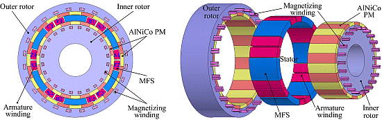
Figure 1 shows the configuration of the proposed EC-MVSG machine, which is the combination of the concepts of the magnetic gearing machine and the memory machine. First, the proposed machine comprises of an outer rotor, an inner rotor and a stator. Both rotor surfaces have 24-pole AlNiCo PMs, which can be independently magnetized and demagnetized. The sandwiched stator is composed of modulated ferromagnetic segments (MFSs) and armature windings. With this topology, the proposed machine can modulate the inner rotor rotating field and the outer rotor rotating field by the MFSs, hence achieving the magnetic gearing effect. Then, since the number of AlNiCo PM pole-pairs of the inner and outer rotors can be flexibly adjusted by the adjacent magnetizing windings, the magnetic gear ratios can be correspondingly changed. In addition, since these magnetizing windings only need to carry temporary current pulses to magnetize or demagnetize the PMs, they are small enough to be embedded into the rotor yoke. This machine is relatively complicated when compared with the traditional PM machines with one airgap [1,2], but the structure is not complicated when compared with those integrated machines with two or three airgaps [5,14,18]. Also, in order to keep the coils away from the inner and outer rotating parts, a good alignment is necessary; otherwise, additional mechanical shield layers will be required, which will increase the airgap length and decrease the machine performance.
Since the proposed EC-MVSG machine integrates two distinct concepts of magnetic gearing and flux-mnemonics, it has many unique features as follows:
The whole structure is compact and robust, and fully utilizes the machine space for accommodating PMs, windings and MFSs. Both rotors have PMs and magnetizing windings, which means both pole-pairs of rotors can be adjusted. The stator not only comprises MFSs, but also artfully incorporates the MFSs into the air space. In this way, although two concepts are created for the machine design, the flux path is very short from the inner rotor to the outer rotor, and armature windings are bypassed, therefore, it can greatly improve the flux transmission efficiency.
The stator is quite different from those magnetic gearing machines which have separate two parts for the MFSs and the armature windings [10,11]. It integrates MFSs and armature windings together, hence effectively decreasing the machine size and improving the power density.
Both rotors accommodate PMs and magnetizing windings, which inherently create the flux-mnemonic feature for PM pole-pairs. Also, it can be found that the rotor space is fully utilized, hence further increasing the material cost-effectiveness. In addition, these 24 pieces of PMs in both rotors can be magnetized or demagnetized to the desired applicable pole-pairs, such as two and four.
The AlNiCo PM is not a rare-earth PM and hence is more abundant and cheap. In addition, it should be noted that two sets of slip rings are needed to access the magnetizing windings of both rotors.
The proposed machine has the capability of gearing effect (with fixed gear ratio) for changing the torque and speed. Namely, if the inner rotor runs at high speed with low-torque output, the outer rotor can run at low speed with high-torque output under a fixed gear ratio.
The proposed machine also has the capability of variable gear ratios for torque and speed variation. Namely, the proposed machine has three gear ratios for its outer-rotor speed over its inner-rotor speed, such as 1:1, −2:1 and −1/2.
3. Machine Operation Principle
3.1. Hysteresis Model of the AlNiCo PM
The AlNiCo PM, created in the 1930s, was widely applied for PM machines due to its high remanence, high thermal stability and high stability [23]. However, the AlNiCo PM has a low coercivity, which easily leads to irreversible demagnetization under unexpected extreme operating conditions. Also, its nonlinear demagnetization curve makes it never superpose on the same recoil line, which means it having unfixed recoil lines for different magnetization levels. As a result, NdFeB PMs with the high coercivity and linear demagnetization curves are currently preferred for PM machines. Figure 2a shows their corresponding B-H curves.
On the other hand, the AlNiCo PM is suitable for memory machines because of its nonlinear demagnetization characteristics. That is, once the demagnetization current is added for a short time and then removed, the operation point will move along the recoil line and stay at a lower magnetization level. It also means that the magnetization level is memorized. As shown in Figure 2b, the AlNiCo PM adopts a parallelogram hysteresis model for this machine design [23]. Its piecewise-linear feature makes it close with the true model and convenient for time-stepping finite-element calculations. It shows that the major hysteresis loop and all the minor hysteresis loops have the same value of coercivity −Hc, but they have different values of remanence Brn.
In detail, the main beelines that represent the magnetizing and demagnetizing processes are marked in Figure 2b with 1, 2 and 3. During the magnetizing process, the operating point moves upward along the Line 1, then leftward along the Line 2, and stays at the operating point of Po. Subsequently, during the demagnetizing process, the operating point moves leftward along the Line 2, then downward along the Line 3, then rightward along the recoil line until settling at the operating point of Qo with a lower flux level. The corresponding equations of these beelines can be respectively expressed as [21–23]:
First, during the initial magnetizing state, each AlNiCo PM element is set to have a constant μr and zero Br. Then, if a temporary positive magnetizing current is added, the magnetizing force H of each element can be calculated with TS-FEM. After the initial external magnetizing current is removed, the reversal point will be determined at some specific value. The corresponding remanence of each AlNiCo PM element can be expressed as follows:
Second, during the working state, the magnetizing force H of each AlNiCo PM element is calculated with FEM when a temporary negative demagnetizing current is added. Meanwhile, Br of each element is obtained based on Equation (2) according to its associated Brn. Also, at each time step, the value of Brn is modified until it converges using the under-relax iteration method, which is given by:
3.2. Pole-Pair Regulation
Since the proposed EC-MVSG machine belongs to the magnetic-gearing machine type, its torque transmission is based on the modulation of the airgap flux density distribution along the radial and circumferential directions, therefore, the airgap flux density space harmonics and the corresponding pole-pair arrangements are governed by [7,19,24]:
Based on the above equation, the so-called magnetic gearing effect will occur, and the gear ratio and speed relationship can be expressed as:
For the proposed machine, the MFS is set to 6. The armature winding is set to three phases with six slots also, which can directly locate in the space between MFSs. The pole-pair numbers of both inner rotor and outer rotor are first set to 12. Then, by magnetizing these PMs to the different directions and amplitudes, the proposed machine will have different pole-pair numbers for both rotors. The first case (Case I) is to magnetize the inner rotor and outer rotor to the same pole-pair number of four. In this case, both rotors will operate at the same direction, which can be seen as the double-rotor machine. The second case (Case II) is to magnetize the inner rotor to the pole-pair of pri = 4 and pr0 = 2. In this case, the outer rotor speed will be twice as the inner rotor speed with contra-rotating direction. The third case (Case III) is to magnetize the inner rotor to the pole-pair of pri = 2 and pr0 = 4. In this case, the outer rotor speed will be 1/2 as the inner rotor speed with contra-rotating direction. Thus, if the inner rotor speed is set to 500 rpm, the outer rotor speed could be 500 rpm, −1000 rpm or −250 rpm corresponding to the gear ratio of Gr1 = 1, Gr2 = −2 or Gr3 = −1/2.
3.3. Electromagnetic Field Analysis
Electromagnetic field analysis has been widely developed for electric machines. Basically, it can be categorized as analytical field calculation and numerical field calculation. The TS-FEM is the one of the most popular numerical field calculation tools. In this paper, the TS-FEM is incorporated with the above parallelogram hysteresis model and developed for analyzing the proposed EC-MVSG machine.
First, the electromagnetic field equation of the machine is governed by [23–25]:
Second, the armature circuit equation of the machine at motoring is given by [25–28]:
Third, the machine motion equation is expressed as [25–28]:
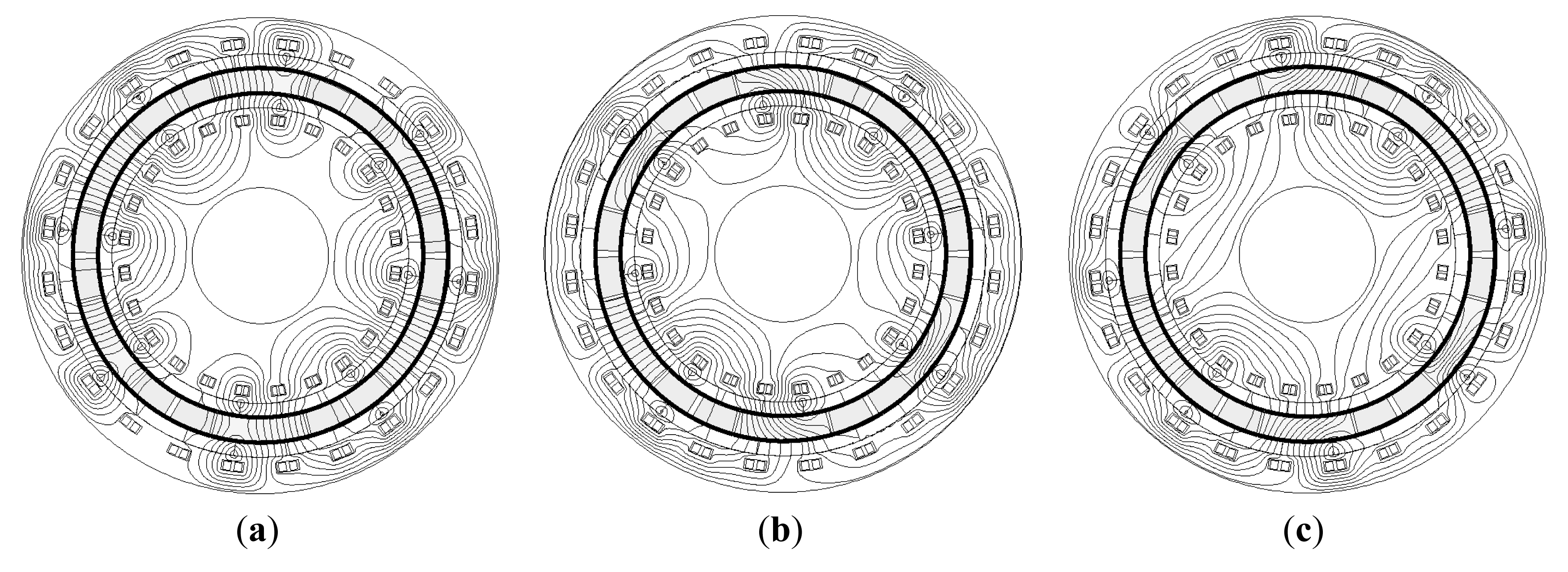
Figure 3 shows the flux lines of the proposed machine with different rotor pole-pair numbers and speeds. It can be seen that Figure 3a has four pole-pairs for both rotors, Figure 3b has four pole-pairs for the inner rotor and two pole-pairs for the outer rotor, and Figure 3c has two pole-pairs for the inner rotor and four pole-pairs for the outer rotor. Thus, it proves that the proposed machine can be magnetized to different pole-pair numbers based on the AlNiCo PMs. However, it should be noted that only the indicated pole-pair number is suitable for the proposed machine to work.
4. Performance Analysis
By performing the TS-FEM, the machine performance can be calculated and obtained. The corresponding machine data is listed in Table 1.
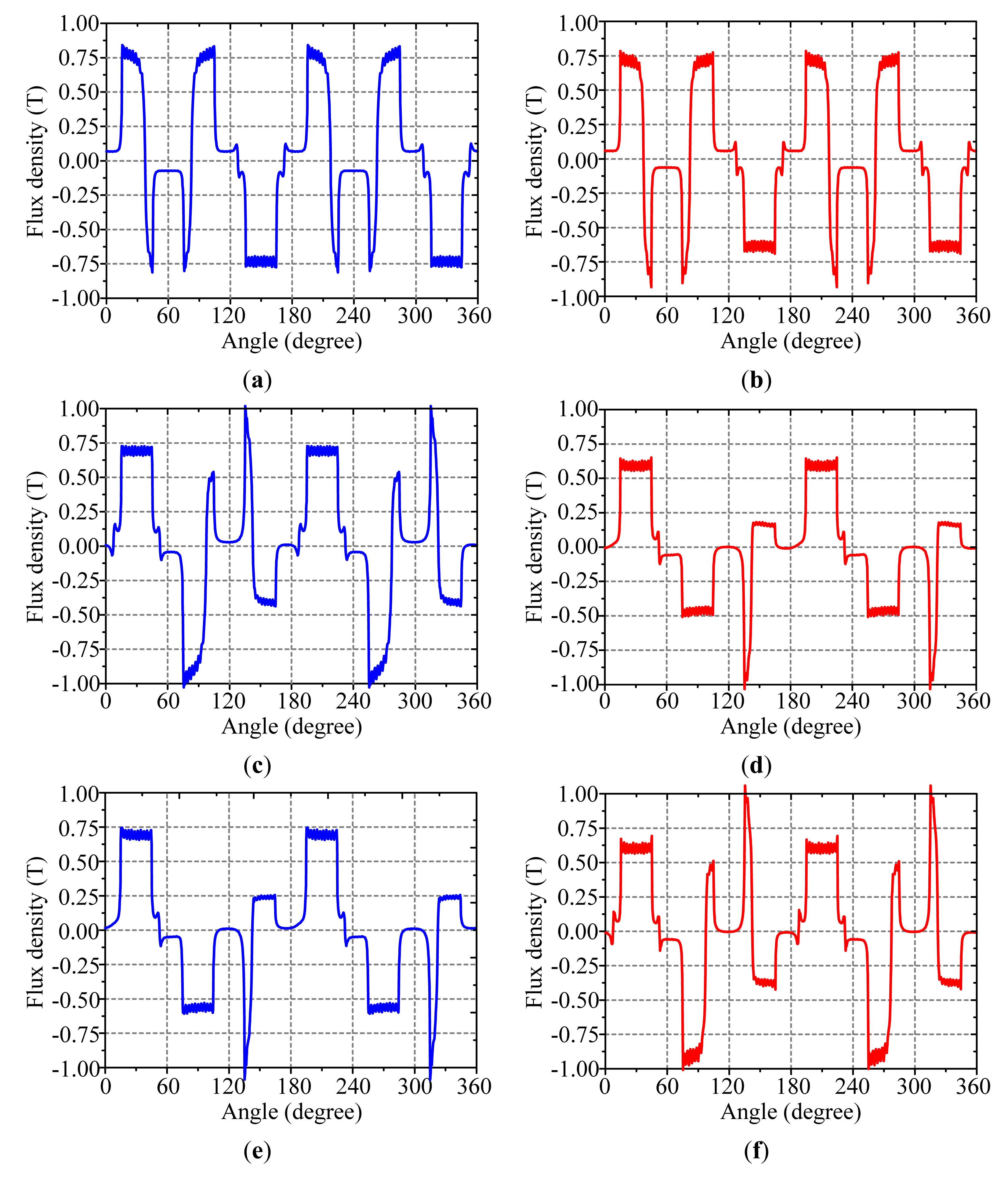
First, the basic characteristics of the proposed EC-MVSG machine are calculated and analyzed. Figure 4 shows the airgap flux density waveforms of the proposed machine under different rotor pole-pair numbers and speeds. It can be found that the amplitude of the airgap flux density is over 0.75 T. Also, they are modulated by the FMSs to different patterns based on different pole-pair numbers. From Figure 4a,b, it can be observed that they have nearly the same flux density waveforms due to the same rotating speed and the same rotor pole-pair numbers. From Figure 4c,d, it can be observed that the outside airgap has been modulated to the small pole-pair number from the big number of the inside airgap. From Figure 4e,f, it can be observed that the outside airgap has been modulated to the big pole-pair number from the small number of the inside airgap. Thus, all these modulation features verify the machine design with EC- MVSG capability.
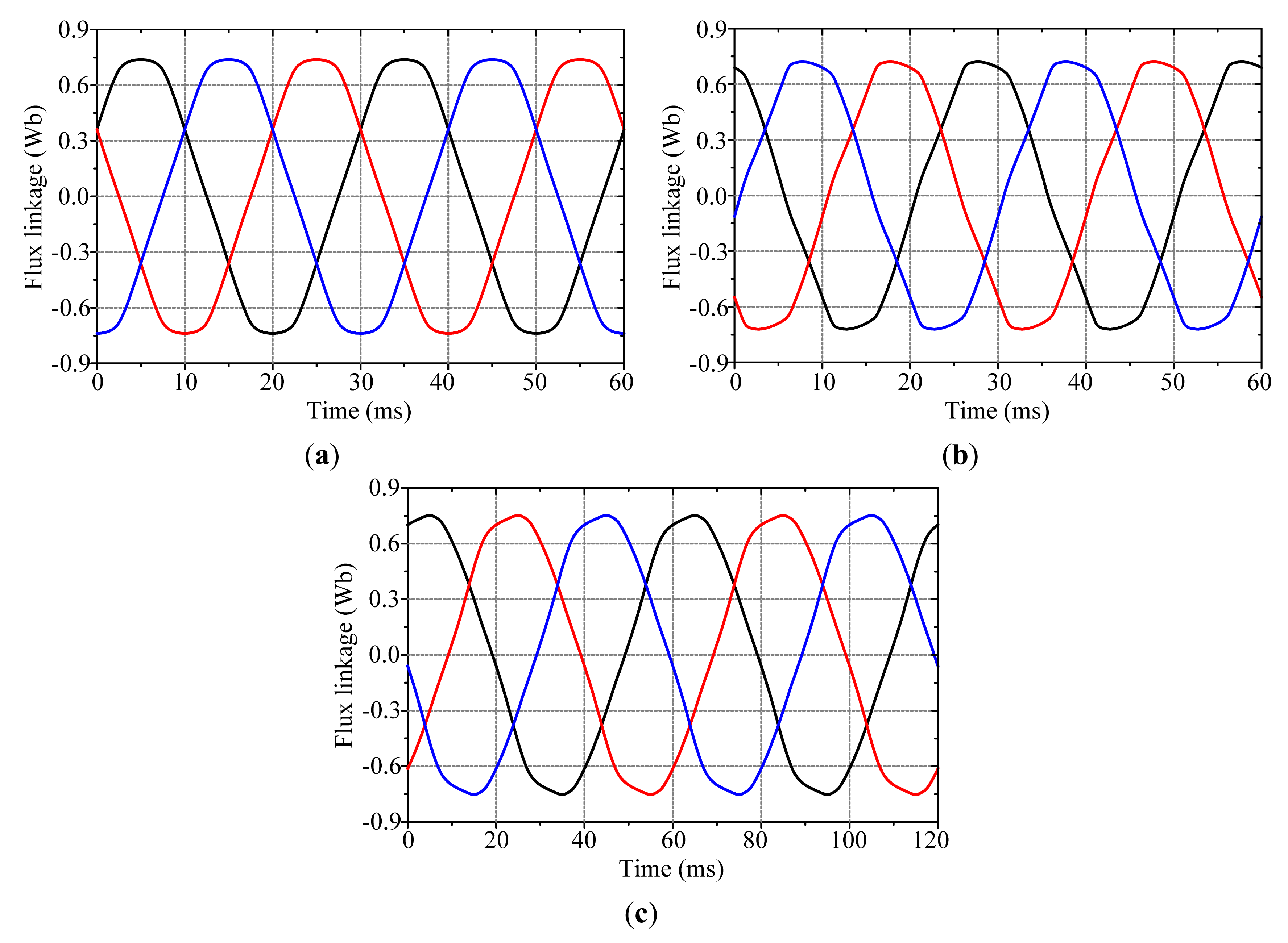
Moreover, Figure 5 shows the flux linkages of the proposed machine under different rotor pole-pair numbers. It can be found that the case of both rotors having the same pole-pair number is much more sinusoidal than the other two cases of both rotors having different pole-pair numbers. In addition, due to the modulation effect of MFSs, the flux linkage periods are different for these three cases for the same inner rotor speed.
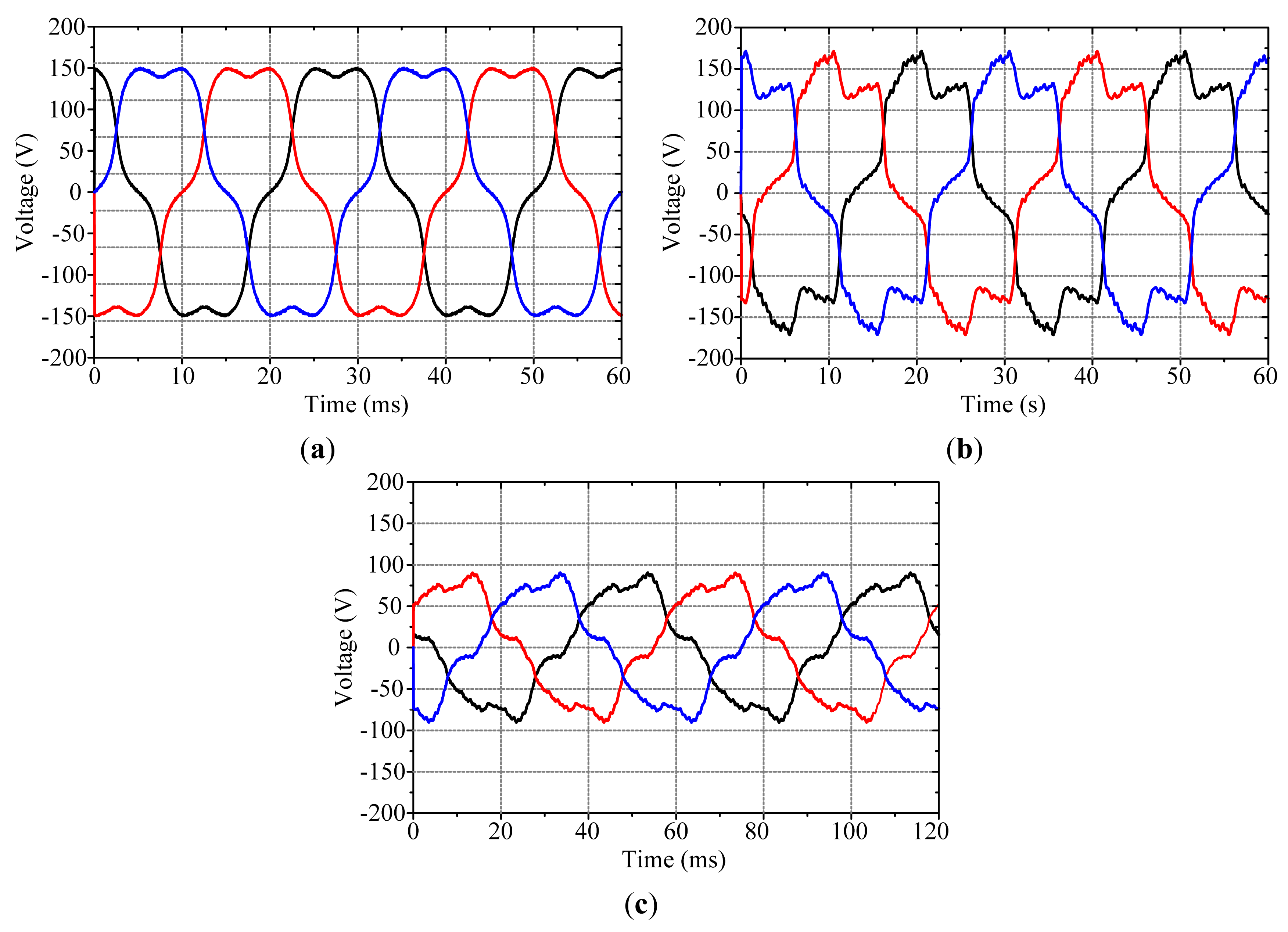
Second, the generating performances of the machine are discussed. Figure 6 shows the no-load EMF waveforms under different rotor pole-pair numbers and speeds. In Case I, this machine becomes a double-rotor magnetic-geared machine MGM and produces an EMF value of 150.0 V. In Case II, this machine has a raising-speed outer rotor with 1000 rpm and offers a higher EMF value of 171.2 V. In Case III, this machine has a decreasing-speed outer rotor with 250 rpm and produces a lower EMF value of 90.2 V. It clearly shows that the proposed machine has three-level gear ratios controlled by the AlNiCo PM magnetization.
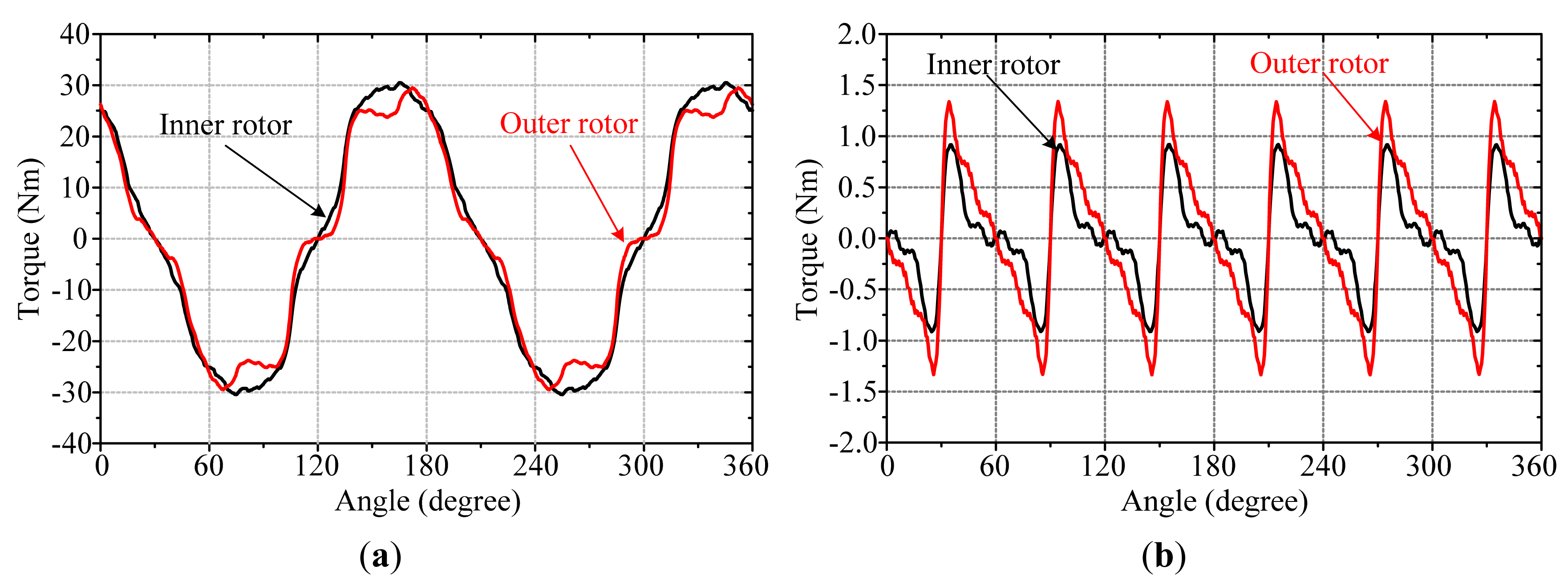
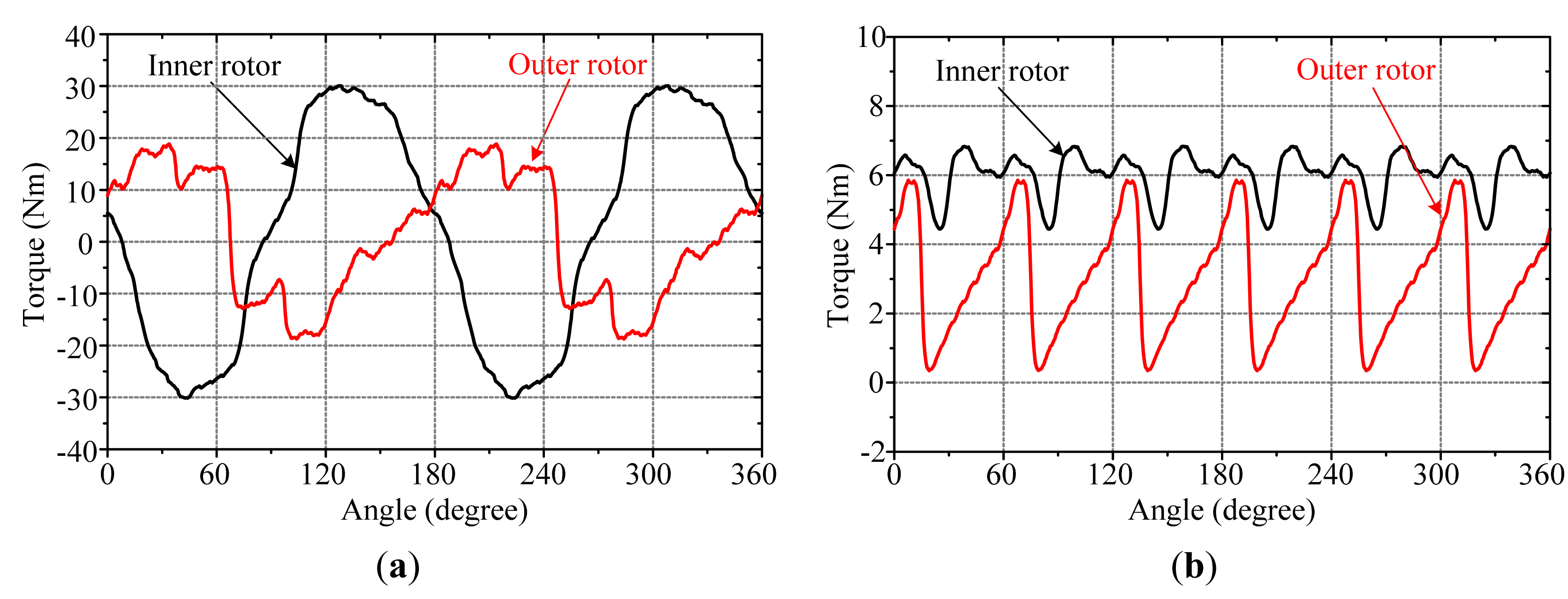
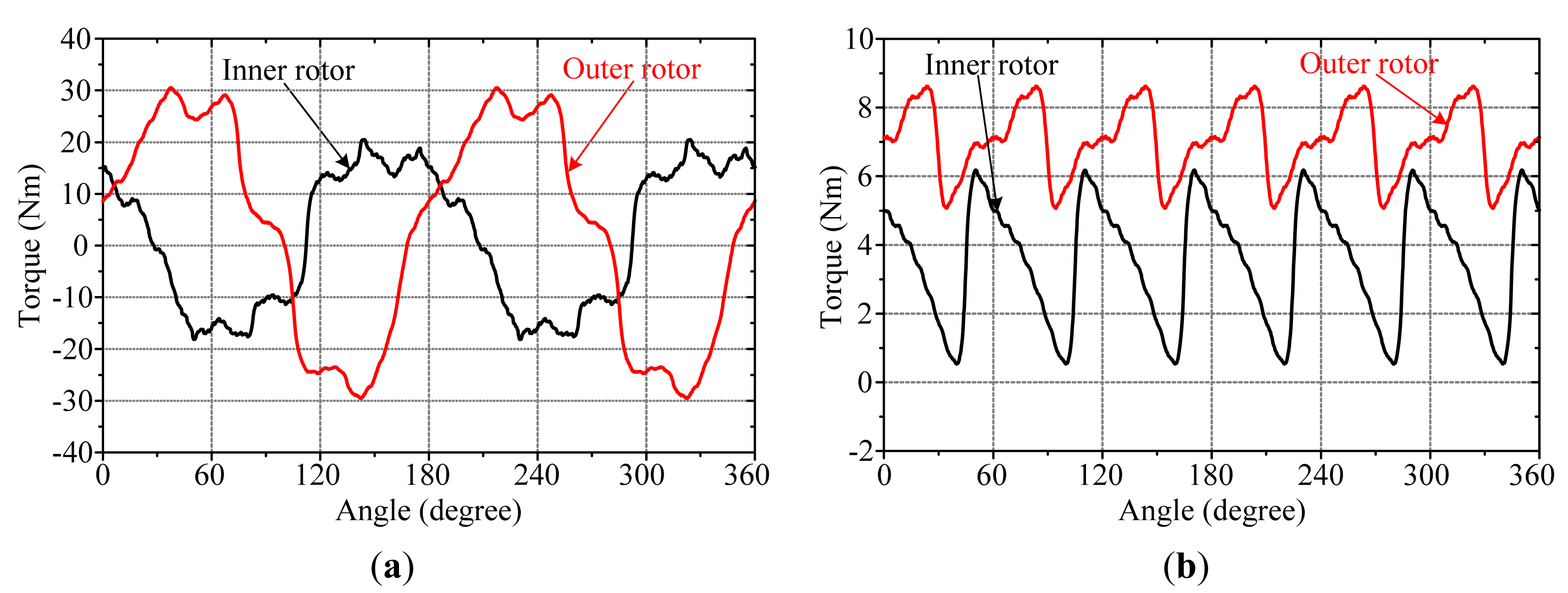
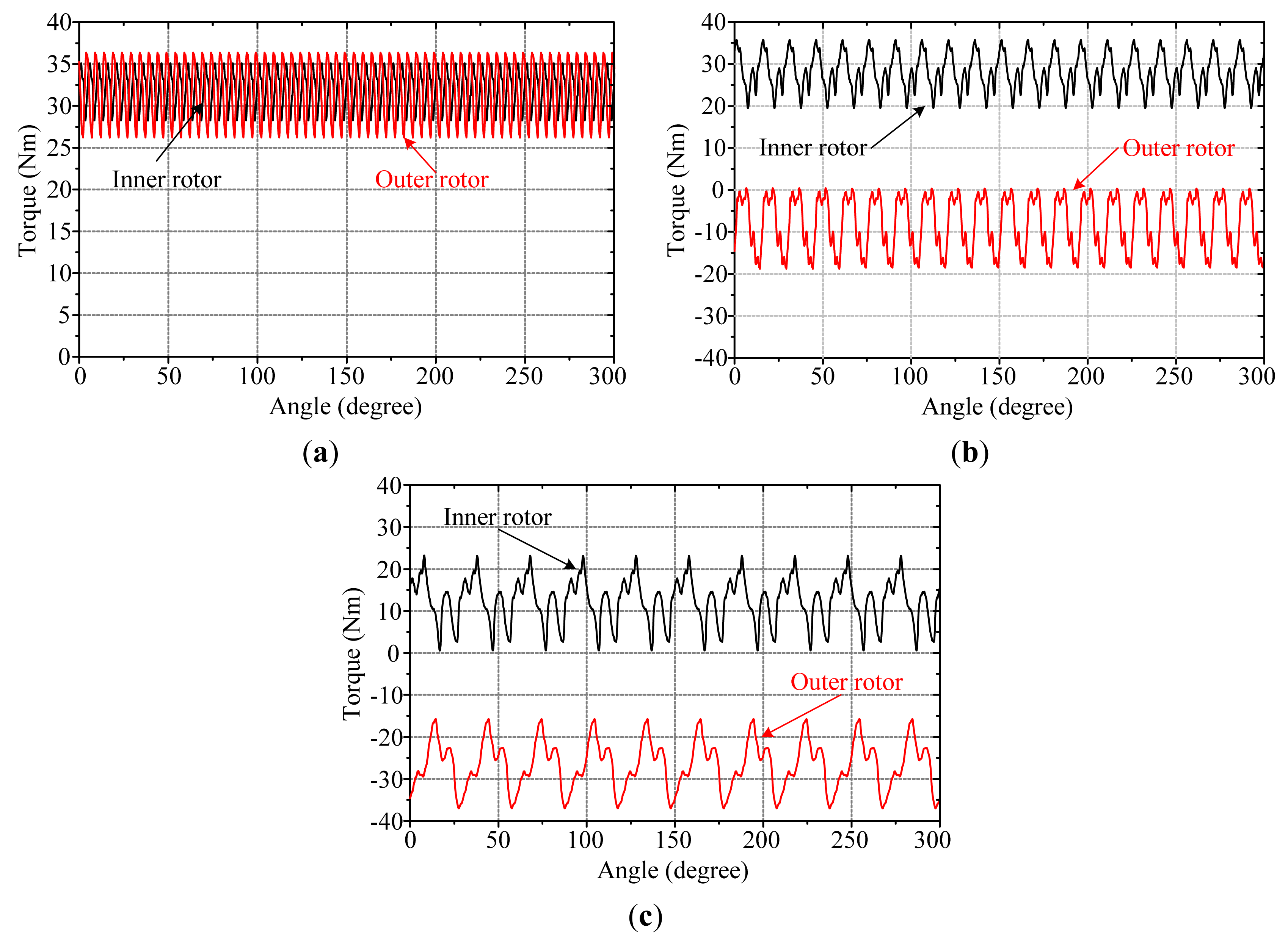
Third, the torque performances of the machine are evaluated and discussed. Figures 78 and 9 show the torque-angle capability and cogging torque of the EC-MVSG machine under the three cases. It should be noted that the torques are generated by feeding the three-phase constant currents of 25 A, −12.5 A and −12.5 A. In Case I, it can be found that both inner rotor and outer rotor can produce about the output torque up to 30.0 Nm. This means that the machine can offer in total a maximum torque of 60.0 Nm for driving. In addition, the corresponding cogging torques are both significantly small and below 5% of their inner and rotor output torques. In Case II, it can be found that the inner output toque and the outer output torque have contrary directions and maximum values up to 30.0 Nm and 19.2 Nm. This shows that the outer rotor torque reduces the inner rotor torque about 37% by the proposed gearing effect, and hence the outer rotor can run at a high speed, which is twice of that of the inner rotor.
In addition, the corresponding cogging torques are not small due to the flux interaction of both rotors, but the cogging torques can be offset to a certain extent. In Case III, it can be found that the inner output toque and the outer output torque also have contrary directions and maximum values up to 20.2 Nm and 30.2 Nm. This indicates that the outer rotor torque increases the inner rotor torque by about 50% with the proposed gearing effect, and hence the outer rotor can run at a slow speed, which is only 1/2 of that of the inner rotor. In addition, the cogging torques have a similar effect as those of Case II. Since both rotor directions and speeds are different in Case II and Case III, the corresponding cogging torques are not zero. When the average cogging torque of the outer rotor transfers its energy to the load, the corresponding energy comes from the inner rotor due to their different speeds and directions. It also means that one of the rotors is connected with the external power source, but the total power produced by the two rotor cogging torques is zero. The cogging torques in Cases II and III are relatively high. Since the two rotors will be connected with the high-inertia engine and high-inertia driveline, respectively, such cogging torques will not significantly affect the engine or vehicle operation.
Moreover, Figure 10 shows the static rated torques of the machine with the same inner rotor speed but different outer rotor speeds. It should be noted that the torques are generated by feeding three-phase sinusoidal currents with an amplitude of 36 A. It can be observed that in Case I, the inner rotor and outer rotor can provide average torque outputs of 32.2 Nm and 31.8 Nm. In Case II, the inner rotor and outer rotor have static average torques of 28.2 Nm and −9.2 Nm. This means that the outer rotor has a downgraded torque output but with the contrary high-speed operation. In Case III, the inner rotor and outer rotor also have contrary torques, which are 12.5 Nm and −26.5 Nm, respectively.
Finally, Table 2 summarizes the torque performances of the proposed EC-MVSG machine. It shows that in Case II and Case III, the torque ripples in one rotor are very large, therefore, the rotor with the large torque ripple should operate in a high-inertia or high-power situation, such as the automobile engine. In Case I, it indicates that the proposed machine can offer a high torque density of 13 Nm/L which is actually due to the simultaneous contribution of two rotor torques. In Case II, the torque density of the outer rotor is quite small (1.87 Nm/L), so that it is mainly used for high-speed occasions. In Case III, the machine outer rotor is capable to offer a torque of 5.38 Nm/L for low-speed occasions. Case I has a better torque density than the normal PM machine of 10 Nm/L, whereas both Case II and Case III have lower torque densities.
In addition, the machine's loss and efficiency are calculated and discussed. The copper loss of the machine at rated conditions is 14.4 W. In Case I, the iron loss is 56.2 W, and the mechanical loss is assumed to be 94.6 W (3% of the output power). Thus, the machine efficiency in Case I is 95.0%. In Case II, the iron loss is 74.6 W, and the mechanical loss is assumed to be 30.2 W (3% of the output power). Thus, the machine efficiency in Case II is 89.4%. In Case III, the iron loss is 44.8 W, and the mechanical loss is assumed to be 47.4 W (3% of the output power). Thus, the machine efficiency in Case III is 93.7%. Therefore, it can be found that the proposed machine has an efficiency comparable with other PM machines.
5. Conclusions
In this paper, a new type of EC-MVSG machine is presented, which possesses electrically controllable gear ratios for automobile driving. First, the machine structure, design principle, and operation principle are discussed and analyzed in detail. The idea is to change the magnetization of the AlNiCo PM to achieve different rotor pole-pair numbers of the machine. Meanwhile, the machine design adopts the magnetic gearing effect. Thus, the proposed machine not only offers a gearing mechanism for torque and speed transmission, but also provides variable gear ratios for torque and speed variations. Namely, the ratio of the outer-rotor speed to the inner-rotor speed has three values: Gr1 = 1, Gr2 = −2 and Gr3 = −1/2, which means that the machine has three operation cases. In this way, the machine is highly promising for automotive applications. The results demonstrate the effectiveness of the proposed machine design.
Acknowledgments
This work was supported by a research grant (Project No. HKU710612E) from the Research Grants Council in Hong Kong Special Administrative Region, China.
Conflicts of Interest
The authors declare no conflict of interest.
References
- Chau, K.T.; Chan, C.C.; Liu, C. Overview of permanent magnet brushless drives for electric and hybrid electric vehicles. IEEE Trans. Ind. Electron. 2008, 55, 2246–2257. [Google Scholar]
- Zhu, Z.Q.; Howe, D. Electrical machines and drives for electric, hybrid and fuel cell vehicles. IEEE Proc. 2007, 95, 746–765. [Google Scholar]
- Zheng, P.; Song, Z.; Bai, J.; Tong, C.; Yu, B. Research on an axial magnetic-field-modulated brushless double rotor machine. Energies 2013, 6, 4799–4829. [Google Scholar]
- Liu, C.; Chau, K.T.; Jiang, J.Z. A permanent-magnet hybrid brushless integrated starter-generator for hybrid electric vehicles. IEEE Trans. Ind. Electron. 2010, 57, 4055–4064. [Google Scholar]
- Zheng, P.; Wu, Q.; Zhao, J.; Tong, C.; Bai, J.; Zhao, Q. Performance analysis and simulation of a novel brushless double rotor machine for power-split HEV applications. Energies 2012, 5, 119–137. [Google Scholar]
- Chau, K.T.; Chan, C.C. Emerging energy-efficient technologies for hybrid electric vehicles. IEEE Proc. 2007, 95, 821–835. [Google Scholar]
- Atallah, K.; Howe, D. A novel high-performance magnetic gear. IEEE Trans. Magn. 2001, 37, 2844–2846. [Google Scholar]
- Rasmussen, P.O.; Andersen, T.O.; Jorgensen, F.T.; Nielsen, O. Development of a high-performance magnetic gear. IEEE Trans. Ind. Appl. 2005, 41, 764–770. [Google Scholar]
- Jian, L.; Chau, K.T. Analytical calculation of magnetic field distribution in coaxial magnetic gears. Prog. Electromagn. Res. 2009, 92, 1–16. [Google Scholar]
- Rasmussen, P.O.; Mortensen, H.H.; Matzen, T.N.; Jahns, T.M.; Toliyat, H.A. Motor Integrated Permanent Magnet Gear with a Wide Torque-Speed Range. Proceedings of the IEEE Energy Conversion Congress and Exposition (ECCE), San Jose, CA, USA, 20–24 September 2009; pp. 1510–1518.
- Chau, K.T.; Zhang, D.; Jiang, J.Z.; Liu, C.; Zhang, Y.J. Design of a magnetic-geared outer-rotor permanent-magnet brushless motor for electric vehicles. IEEE Trans. Magn. 2007, 43, 2504–2506. [Google Scholar]
- Jian, L.; Chau, K.T.; Jiang, J.Z. A magnetic-geared outer-rotor permanent-magnet brushless machine for wind power generation. IEEE Trans. Ind. Appl. 2009, 45, 954–962. [Google Scholar]
- Miller, J.M. Hybrid electric vehicle propulsion system architectures of the e-CVT type. IEEE Trans. Power Electron. 2006, 21, 756–767. [Google Scholar]
- Hoeijmakeer, M.J.; Ferreira, J.A. The electric variable transmission. IEEE Trans. Ind. Appl. 2006, 42, 1092–1100. [Google Scholar]
- Rossi, C.; Corbelli, P.; Grandi, G. W-CVT Continuously Variable Transmission for Wind Energy Conversion System. Proceedings of the Power Electronics and Machines in Wind Applications (PEMWA), Lincoln, NE, USA, 24–26 June 2009; pp. 1–10.
- Sun, X.; Cheng, M.; Hua, W.; Xu, L. Application of Electrical Variable Transmission in Wind Power Generation System. Proceedings of the IEEE Energy Conversion Congress and Exposition (ECCE), Atlanta, GA, USA, 12–16 September 2010; pp. 1529–1536.
- Huang, C.C.; Tsai, M.C.; Dorrell, D.G.; Lin, B.J. Development of a magnetic planetary gearbox. IEEE Trans. Magn. 2008, 44, 403–412. [Google Scholar]
- Jian, L.; Chau, K.T. Design and analysis of a magnetic-geared electronic-continuously variable transmission system using finite element method. Prog. Electromagn. Res. 2010, 107, 47–61. [Google Scholar]
- Liu, C.; Chau, K.T. Electromagnetic design and analysis of double-rotor flux-modulated permanent-magnet machines. Prog. Electromagn. Res. 2012, 131, 81–97. [Google Scholar]
- Ostovic, V. Memory motors. IEEE Ind. Appl. Mag. 2003, 9, 52–61. [Google Scholar]
- Liu, H.; Lin, H.; Zhu, Z.Q.; Huang, M.; Jin, P. Permanent magnet remagnetization physics of a variable flux memory motor. IEEE Trans. Magn. 2010, 46, 1679–1682. [Google Scholar]
- Lee, J.H.; Hong, J.P. Permanent magnet demagnetization characteristic analysis of a variable flux memory motor using coupled Preisach modeling and FEM. IEEE Trans. Magn. 2008, 44, 1550–1553. [Google Scholar]
- Yu, C.; Chau, K.T. Design, analysis, and control of DC-excited memory motors. IEEE Trans. Energy Convers. 2011, 26, 479–489. [Google Scholar]
- Liu, C.; Chau, K.T.; Zhang, Z. Novel design of double-stator single-rotor magnetic-geared machines. IEEE Trans. Magn. 2012, 48, 3234–3237. [Google Scholar]
- Salon, S.J. Finite Element Analysis of Electrical Machines; Kluwer Academic Publisher: Boston, MA, USA, 1995. [Google Scholar]
- Liu, C.; Chau, K.T.; Jiang, J.Z. Design of a new outer-rotor permanent-magnet hybrid machine for wind power generation. IEEE Trans. Magn. 2008, 44, 1494–1497. [Google Scholar]
- Liu, C.; Chau, K.T.; Jiang, J.Z.; Niu, S. Comparison of stator-permanent-magnet brushless machines. IEEE Trans. Magn. 2008, 44, 4405–4408. [Google Scholar]
- Liu, C.; Chau, K.T.; Li, W. Comparison of fault-tolerant operations for permanent-magnet hybrid brushless motor drive. IEEE Trans. Magn. 2010, 46, 1378–1381. [Google Scholar]


| Item | Value | Item | Value |
|---|---|---|---|
| Outer rotor outside diameter | 280.0 mm | Number of MFSs | 6 |
| Outer rotor inside diameter | 221.2 mm | Case I: number of outer rotor PM pole-pair | 4 |
| Inner rotor outside diameter | 190.0 mm | Case I: number of inner rotor PM pole-pair | 4 |
| Inner rotor inside diameter | 80.0 mm | Case II: number of outer rotor PM pole-pair | 4 |
| Stator outside diameter | 220.0 mm | Case II: number of inner rotor PM pole-pair | 2 |
| Stator inside diameter | 191.2 mm | Case III: number of outer rotor PM pole-pair | 2 |
| Outside airgap length | 0.6 mm | Case III: number of inner rotor PM pole-pair | 4 |
| Inside airgap length | 0.6 mm | Number of phases | 3 |
| Shaft length | 80.0 mm | Number of stator slots | 6 |
| Volume | 4,926,017 mm3 | - | - |
| Item | Inner rotor | Outer rotor |
|---|---|---|
| Maximum value of torque-angle capability in Case I | 30.2 Nm | 30.0 Nm |
| Maximum value of torque-angle capability in Case II | 30.0 Nm | 19.2 Nm |
| Maximum value of torque-angle capability in Case III | 20.2 Nm | 30.2 Nm |
| Cogging torque in Case I | 0.9 Nm | 1.3 Nm |
| Cogging torque in Case II | 6.9 Nm | 5.9 Nm |
| Cogging torque in Case III | 6.1 Nm | 8.8 Nm |
| Rated torque in Case I | 32.2 Nm | 31.8 Nm |
| Rated torque in Case II | 28.2 Nm | −9.2 Nm |
| Rated torque in Case III | 12.5 Nm | −26.5 Nm |
| Torque ripple in Case I | 20.4% | 30.6% |
| Torque ripple in Case II | 56.2% | 208.2% |
| Torque ripple in Case II | 179.8% | 79.8% |
| Torque density in Case I | 6.54 kNm/m3 | 6.46 kNm/m3 |
| Torque density in Case II | 5.73 kNm/m3 | 1.87 kNm/m3 |
| Torque density in Case III | 2.54 kNm/m3 | 5.38 kNm/m3 |
© 2014 by the authors; licensee MDPI, Basel, Switzerland This article is an open access article distributed under the terms and conditions of the Creative Commons Attribution license ( http://creativecommons.org/licenses/by/3.0/).
Share and Cite
Liu, C.; Chau, K.T. Electromagnetic Design of a New Electrically Controlled Magnetic Variable-Speed Gearing Machine. Energies 2014, 7, 1539-1554. https://doi.org/10.3390/en7031539
Liu C, Chau KT. Electromagnetic Design of a New Electrically Controlled Magnetic Variable-Speed Gearing Machine. Energies. 2014; 7(3):1539-1554. https://doi.org/10.3390/en7031539
Chicago/Turabian StyleLiu, Chunhua, and K. T. Chau. 2014. "Electromagnetic Design of a New Electrically Controlled Magnetic Variable-Speed Gearing Machine" Energies 7, no. 3: 1539-1554. https://doi.org/10.3390/en7031539