Part-Load Performance of aWet Indirectly Fired Gas Turbine Integrated with an Organic Rankine Cycle Turbogenerator

Abstract
: Over the last years, much attention has been paid to the development of efficient and low-cost power systems for biomass-to-electricity conversion. This paper aims at investigating the design- and part-load performance of an innovative plant based on a wet indirectly fired gas turbine (WIFGT) fueled by woodchips and an organic Rankine cycle (ORC) turbogenerator. An exergy analysis is performed to identify the sources of inefficiencies, the optimal design variables, and the most suitable working fluid for the organic Rankine process. This step enables to parametrize the part-load model of the plant and to estimate its performance at different power outputs. The novel plant has a nominal power of 250 kW and a thermal efficiency of 43%. The major irreversibilities take place in the burner, recuperator, compressor and in the condenser. Toluene is the optimal working fluid for the organic Rankine engine. The part-load investigation indicates that the plant can operate at high efficiencies over a wide range of power outputs (50%–100%), with a peak thermal efficiency of 45% at around 80% load. While the ORC turbogenerator is responsible for the efficiency drop at low capacities, the off-design performance is governed by the efficiency characteristics of the compressor and turbine serving the gas turbine unit.1. Introduction
In March 2007, the Council of the European Union [1] approved the so-called 20-20-20 goals. One of the ambitious targets is to reach a minimum of a 20% share of renewable energy in the European Union by the end of 2020. While the major contribution should come from wind and solar power [2], biomass is expected to play a relevant role in the future energy scenario. The Danish association of engineers (IDA) has recently proposed to increase the total amount of biomass resources in Denmark from the present 90 PJ to 180 PJ in 2030 [2]. The IDA targets an energy system for Denmark based solely on renewable energy sources, and the association estimates that by 2050 biomass may cover 80% of the Danish primary energy consumption.
Conventional technologies for biomass-to-electricity conversion are poor in terms of performance. According to Wood and Rowley [3], kW-size Stirling engines coupled with updraft gasifiers provide a thermal efficiency of around 18%. Ahrenfeldt et al. [4] reported of a two-stage gasifier coupled with a gas engine giving a thermal efficiency of 25%. Organic Rankine cycle (ORC) power units can boost the performance up to 25%–35% [5]. While integrated gasification combined cycles (IGCCs) present thermal efficiencies up to 45%, limitations in the performance of the steam Rankine cycle plant restrict the minimum size of this technology to values higher than 10 MW [6]. Power systems integrating solid oxide fuel cells (SOFCs) with different bottoming units have recently been proposed [7,8]. Although the development of SOFCs is currently limited by high investment costs, thermal efficiencies up to 60% are theoretically achievable [7].
Kautz and Hansen [9] proposed the use of indirectly fired gas turbines (IFGTs) in biomass applications. Findings indicate that the IFGT could reach a thermal efficiency up to 30% depending on the size of the system. Bram et al. [10] provided a comprehensive review of IFGTs in operation, with particular focus on technical and economic aspects. Datta et al. [11] conducted an exergy analysis of an IFGT for decentralized power generation supplying the local needs of remote areas. In this case study the major exergy destructions occur in the gasifier, the burner and in the primary heat exchanger. Elmegaard et al. [12] performed a parametric study of a wet indirectly fired gas turbine (WIFGT), where a dryer is added to decrease the moisture content of wet biomass. The thermal efficiency was found to be around 25% for all moisture contents of the combustible. Invernizzi et al. [13] proposed the integration of IFGTs with ORC power modules. The plant was analyzed using the first principle of thermodynamics. Toluene and hexamethyldisiloxane were proposed as the working fluids for the ORC unit and a preliminary design of the expander was performed. This paper aims at evaluating the optimal design and the part-load performance of an innovative plant consisting of a WIFGT fueled by woodchips and an ORC turbogenerator. The plant layout proposed by Invernizzi et al. [13] is modified by exploiting the air exiting the gas turbine unit to oxidize the biomass in the burner and by including a dryer for the combustion of the wet woodchips. An exergy analysis is performed to identify the thermodynamic irreversibilities of the plant and the optimal design variables. The working fluid circulating in the ORC module is selected among five candidates determined upon consideration of thermal stability, availability, health, fire and physical hazards. As element of novelty, the part-load characteristics of the power system is assessed by using state-of-the-art off-design models for each plant component and by proposing appropriate control strategies for the gas turbine module and the ORC turbogenerator.
2. Plant Configuration
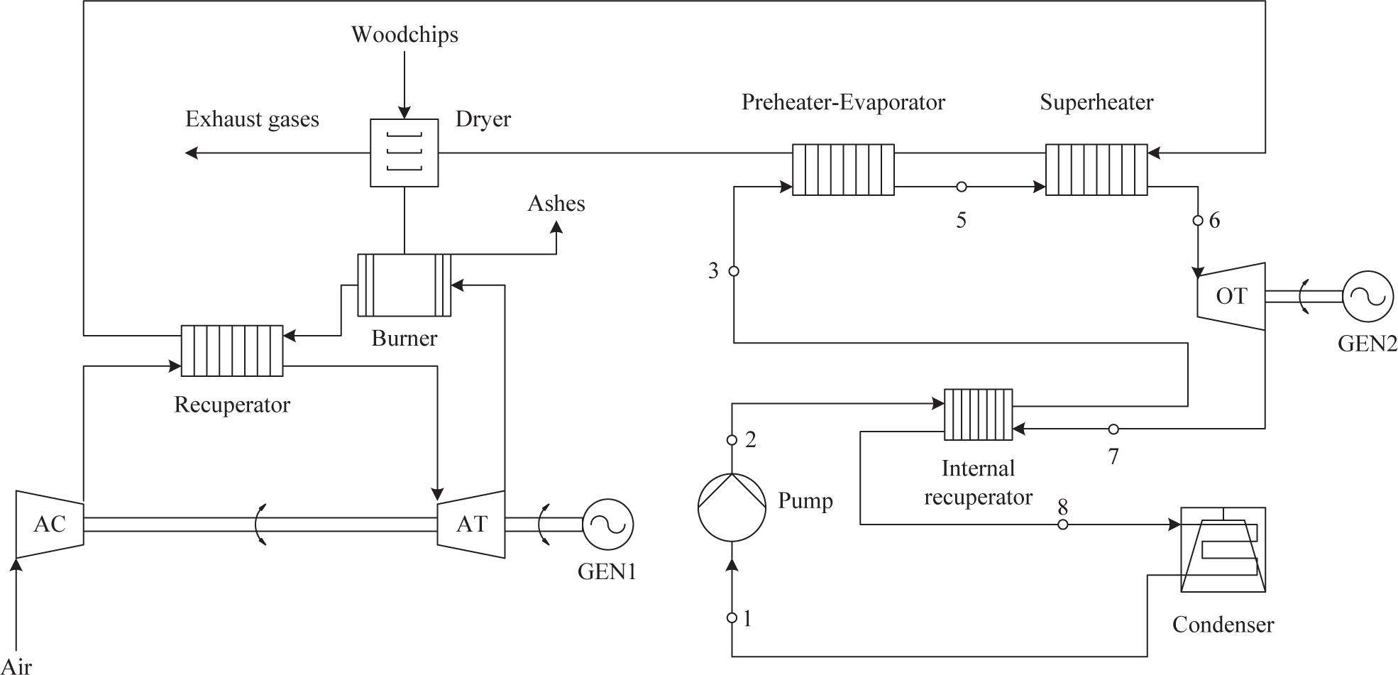
Figure 1 shows the system layout consisting of the WIFGT fueled by woodchips and the ORC turbogenerator. The wet wood is first dried so as to tolerate combustion of biomass with high moisture content. The dried woodchips are then fired in the burner by exploiting the stream exiting the air turbine (AT). The ashes formed during the combustion process are removed from the burner. The air compressor (AC) pressurizes ambient air, which is then heated up in the recuperator and expanded in the AT. A single shaft connects mechanically the compressor and the turbine to the electric generator.
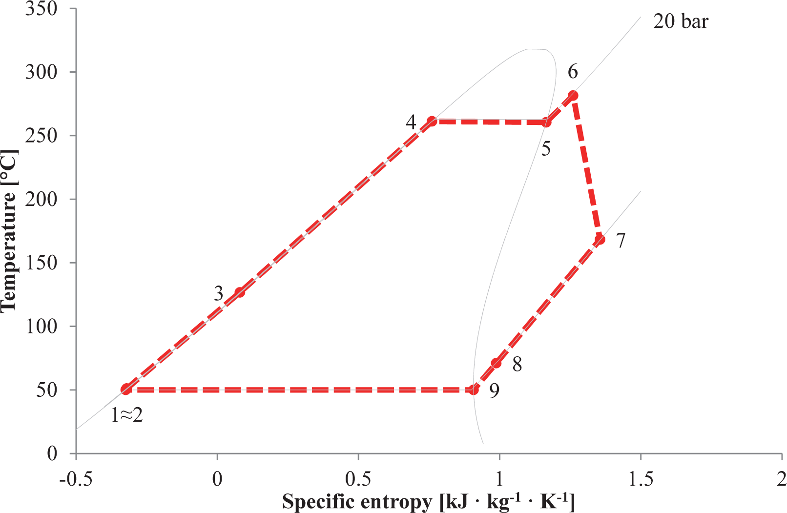
The combustion products are first cooled down inside the recuperator. Subsequently, they power the ORC unit by delivering the heat to the superheater and the preheater-evaporator. The gaseous stream supplies the heat required for the drying process and it absorbs the moisture content of the wood before being released to the environment. In the ORC unit the organic compound exiting the superheater expands in the turbine (OT), which is connected with a dedicated shaft to a separate electric generator. To enhance the system performance, an internal recuperator is thus added to decrease the energy contained in the stream exiting the ORC expander. Figure 2 illustrates the T-s diagram of the ORC turbogenerator employing toluene as working fluid. The nodes where the fluid is in saturated conditions, i.e., Nodes 4 and 9, are not reported in the plant layout as evaporation and condensation start inside the preheater-evaporator and the condenser.
Table 1 lists the plant parameters that are maintained constant in the simulations. The targeted net power output is around 200 kW for an estimated cultivation area of 0.5 km2, thus yielding to a mass flow of woodchips of 180 kg · h−1 [8]. The figures for the lower heating value, the composition and the moisture content are acquired from Cocco et al. [14]. As fuel impurities, e.g., sulfur or chloride, may lead to acid formation and thus compromise the integrity of the exhaust ducts, the temperature of the combustion products released to the ambient is limited to 110 °C. The recuperator included in the gas turbine package is a finned-plate heat exchanger (see Kays and London [15]) made up of ferritic oxide dispersion strengthened alloys. As reported by Bram et al. [10], these materials, successfully tested with wall temperatures up to 1150 °C, allow for operations at turbine inlet temperatures around 900 °C. Therefore, the combustion temperature and the minimum allowable temperature difference in the recuperator are fixed to 1000 °C and 100 °C, respectively.
In view of the net power output (120–180 kW) and pressure ratio (2–8) of the gas turbine unit, the turbomachinery consists of a single-stage centrifugal compressor and a radial turbine rotating at a design-point rotational speed of 68,384 rpm [16]. Reasonable figures for the isentropic and mechanical efficiencies of the turbomachinery are acquired from Dixon and Hall [17]. As the gas turbine engine generates high-frequency power, the electric generator is equipped with a rectifier-inverter system. This device flattens the high frequency output of the high speed generator and it can deliver the requested grid frequency from the rectified direct current.
Estimating the size of the ORC turbogenerator to be between 60 kW and 80 kW, the expander is a one- or two-stage axial turbine with an isentropic efficiency equal to 80% [18]. Exploiting the advantage of the low speed of sound of organic vapors, the mechanical shaft connecting the ORC turbine (OT) to the electric generator can rotate at 3000 rpm, thus avoiding the need for a frequency converter or gear box. The heat transfer equipment is of the flat-plate type, while the pumping process is performed using a centrifugal pump with a mechanical efficiency equal to 70%. The ORC unit comprises an air-cooled condenser with the condensation temperature set to 50 °C.
The selection of the working fluid constitutes a crucial aspect for the design of highly-efficient and cost-competitive ORC power modules. As surveyed by Trapp and Colonna [19], the ideal candidate should be available at low costs, have low environmental impact, flammability and toxicity. Moreover, the plant performances and the component design are pivotal aspects of the fluid selection process. In light of the aforementioned considerations, five hydrocarbons are considered as possible candidates. Table 2 lists the thermodynamic properties at the critical point, the health, physical and environmental hazard levels, the ozone depletion potential (ODP) and the global warming potential (GWP) in 100 years equivalent. Fluid hazards are quantified according to the hazardous materials identification system (HMIS) developed by the American coatings association [20]. The figures for the GWP and ODP values of the hydrocarbons are obtained from the open literature [21,22]. For two of these compounds (benzene and cyclopentane) the thermal stability was experimentally verified up to a temperature of 300 °C, see Andersen and Bruno [23] and Ginosar et al. [24], respectively. Cyclopentane is also currently adopted for operating ORC systems in this range of temperatures, see Del Turco et al. [25]. Note that the authors performed additional calculations to evaluate the opportunities of utilizing other chemical compounds, i.e., standard refrigerants and siloxanes. However, the results indicated that other fluid candidates deliver much lower performances compared with those listed in Table 2. In this regard, for standard refrigerants (such as R245fa and R1234yf) the thermal stability limits their maximum operating temperatures, thus inducing high heat transfer irreversibilities in the heat addition process.
3. Methods
3.1. The Simulation Tool
The results of this paper are obtained with the software dynamic network analysis (DNA) utilized for energy system analyses. The open source software is the present result of ongoing development at the Department of Mechanical Engineering, Technical University of Denmark (Kongens Lyngby, Denmark), which began in 1988 [26]. The program formulates the physical model by connecting the relevant component models through nodes and by including operating conditions for the complete system. The physical model is converted into a set of mathematical equations to be solved numerically. The algebraic equations include mass and energy conservation for all components and nodes, as well as relations for thermodynamic properties of the fluids involved. The program includes a component library with models for a large number of different components existing within energy systems. Components are modeled with a number of constitutive equations representing their physical properties, i.e., heat transfer coefficients for heat exchangers and isentropic efficiencies for compressors and turbines. Steady-state (involving algebraic equations), dynamic (involving differential equations) simulations and exergy analyses can be conducted. The program has been successfully used to model energy systems in research fields such as refrigeration, power plants, fuel cells and gasification. The fluid library has been recently extended by linking DNA with the commercial software REFPROP© [27], Version 9.1. The source code, provided under license in Fortran language, is compiled together with DNA to form a single software. Accordingly, the thermodynamic properties of each fluid candidate listed in Table 2 are evaluated using the equations of state programmed by Lemmon et al. [27]. Air and combustion products are instead treated as ideal gas mixtures.
3.2. Exergy Analysis
Mapping the thermodynamic inefficiencies by conducting an exergy analysis allows for suggesting measures for improving the system performance, ultimately leading to the optimal design-point of the plant. Bejan et al. [28] define exergy as the maximum theoretical useful work (shaft work or electrical work) obtainable as the systems interact to equilibrium, the heat transfer occurring reversibly with the environment only. The exergy destruction accounts, therefore, for the additional fuel use required for producing the desired output. The exergy analysis conducted in this work follows the methodology suggested by Bejan et al. [28]. An exergetic assessment reveals the locations and magnitudes of the thermodynamic irreversibilities taking place in a system. For an open system at steady-state, the exergy balance can be written as:
3.3. Part-Load Models and Control Strategies
For the purpose of this work, the component library in DNA was extended with steady-state models describing the part-load characteristics of each plant constituent. The off-design models of the centrifugal compressor and radial turbine are based on the component maps contained in the software developed by Kurzke [29]. The compressor and turbine maps used here are those originally from Klassen et al. [16] and Pullen et al. [30]. These maps are represented by tables stating values for reduced flow, pressure ratio, isentropic efficiency and speed of revolution for the complete operating range of the components. Following the method proposed in Kurzke [29], the maps are scaled so that they can represent the part-load characteristics of the centrifugal compressor and radial turbine.
For all heat exchangers, the heat transfer coefficients in off-design conditions are evaluated with the relation proposed in Incropera et al. [31]. Owing to their relatively small contributions, the thermal resistance in the radial direction and thermal diffusion in the axial direction are neglected. In the case of the preheater-evaporator and the superheater, the heat transfer coefficient between the hot stream and the plate surface is much lower than the one between the plate surface and the ORC working fluid flow. Therefore, the overall heat transfer is essentially dependent on the hot side only, and the working fluid temperature is always close to the surface temperature of the plate. The thermal interaction between the wall and the cold stream is described by specifying a sufficiently high constant heat transfer coefficient, so that the fluid temperature is close to the wall temperature, and the overall result is dominated by the hot side heat transfer. The condenser is trivially modeled as a fixed pressure component. This is justified assuming to control the coolant flow in such a way that the condenser pressure is nearly constant. The pressure drops occurring in the heat exchangers, burner and dryer are evaluated assuming a quadratic dependence with the volumetric flow rate.
The ORC expander is a one- or two-stage axial machine, leading to large pressure ratios across each stage. As a consequence, the flow is usually supersonic at the outlet of the first stator. Therefore, the expander is modeled as an equivalent choked de Laval nozzle (see Appendix A), whose throat flow passage area is the sum of the throat areas of the nozzles constituting the first stator row. To predict the off-design performance of the OT, the correlation relating the isentropic efficiency and the non-dimensional flow coefficient proposed by Schobeiri [32] is utilized. The isentropic efficiency of the ORC pump at part-load is derived using the methodology proposed by Veres [33], while the part-load characteristics of the electric generators are modeled using the analytical expression suggested by Haglind and Elmegaard [34]. A full list of equations describing the off-design characteristics of each plant component is reported in Appendix A.
As for the control strategies, it is decided to operate the plant such that the combustion temperature remains equal to the design-point value, i.e., 1000 °C, at all power outputs. As proposed by Campanari [35] for integrated SOFC and microturbine systems, this task can be accomplished using a rectifier-inverter unit that manipulates the rotational speed of the shaft connecting the centrifugal compressor and the radial turbine to the electric generator. The tracked set-point of the control system is, accordingly, the temperature of the combustion products exiting the burner. The rectifier-inverter system is also necessary to maintain the plant synchronized with the electric grid operating at 50 Hz (or 60 Hz). This operational scheme enables to keep the temperature at the inlet of the radial turbine nearly constant, and, ultimately, to enhance the performance of the system. The ORC power module operates in sliding-pressure mode. The evaporating pressures are governed by the system of Equation (A1), the pump curve and the heat balances in the heat transfer equipment. Additionally, a variable frequency electric motor adjusts the rotational speed of the pump so as to ensure saturated vapor conditions at the inlet of the superheater (see Point 5 in Figures 1 and 2) at any load set-points. In this way, the superheater design can be optimized for gas-to-vapor operating conditions. Moreover, the preheater-evaporator does not have to cope with the sharp variations of the heat transfer coefficient on the cold side caused by the presence of superheated vapor at part-loads.
4. Results
4.1. Exergy Analysis
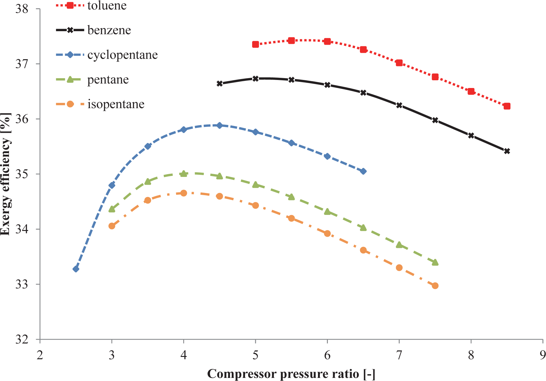
Figure 3 relates the exergy efficiency of the plant to the design-point pressure ratio of the centrifugal compressor. In this analysis the turbine inlet pressure of the ORC turbogenerator is kept constant to 20 bar. For each working fluid candidate there is one pressure ratio that maximizes the exergy efficiency. The optimal value ranges from 4.0 (isopentane and pentane) to 5.5 (toluene and benzene), while the peak of the exergy efficiency spans from 34.7% (isopentane) to 37.4% (toluene).
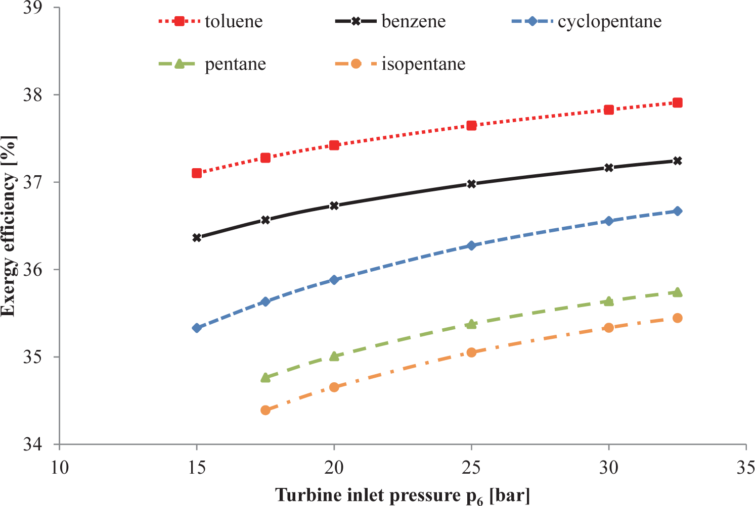
Figure 4 illustrates the influence of the pressure at the inlet of the ORC expander on the plant exergy efficiency. Increased pressures lead to slightly higher performances for all fluids with increments of around 1.0%-points moving from 15 bar to 35 bar. On the other hand, augmenting the turbine inlet pressure, with a fixed number of stages, deteriorates the expander efficiency by virtue of the higher expansion ratios. The turbine performance relates to the volume flow ratio across each stage and to the turbine size parameter [36]. As reported by Macchi and Perdichizzi [36], high stage efficiencies are obtainable with volumetric flow ratios of around 1–10 and turbine size parameters between 1 cm and 50 cm. Examining the optimal case, i.e., toluene as working fluid and a compressor pressure ratio of 5.5, and assuming two stages for the ORC expander, the stage volumetric flow ratio exceeds 15 for pressures larger than 30 bar. In order to respect the assumption of a design-point isentropic efficiency of 80%, it is thus decided to maintain the turbine inlet pressure equal to 20 bar.
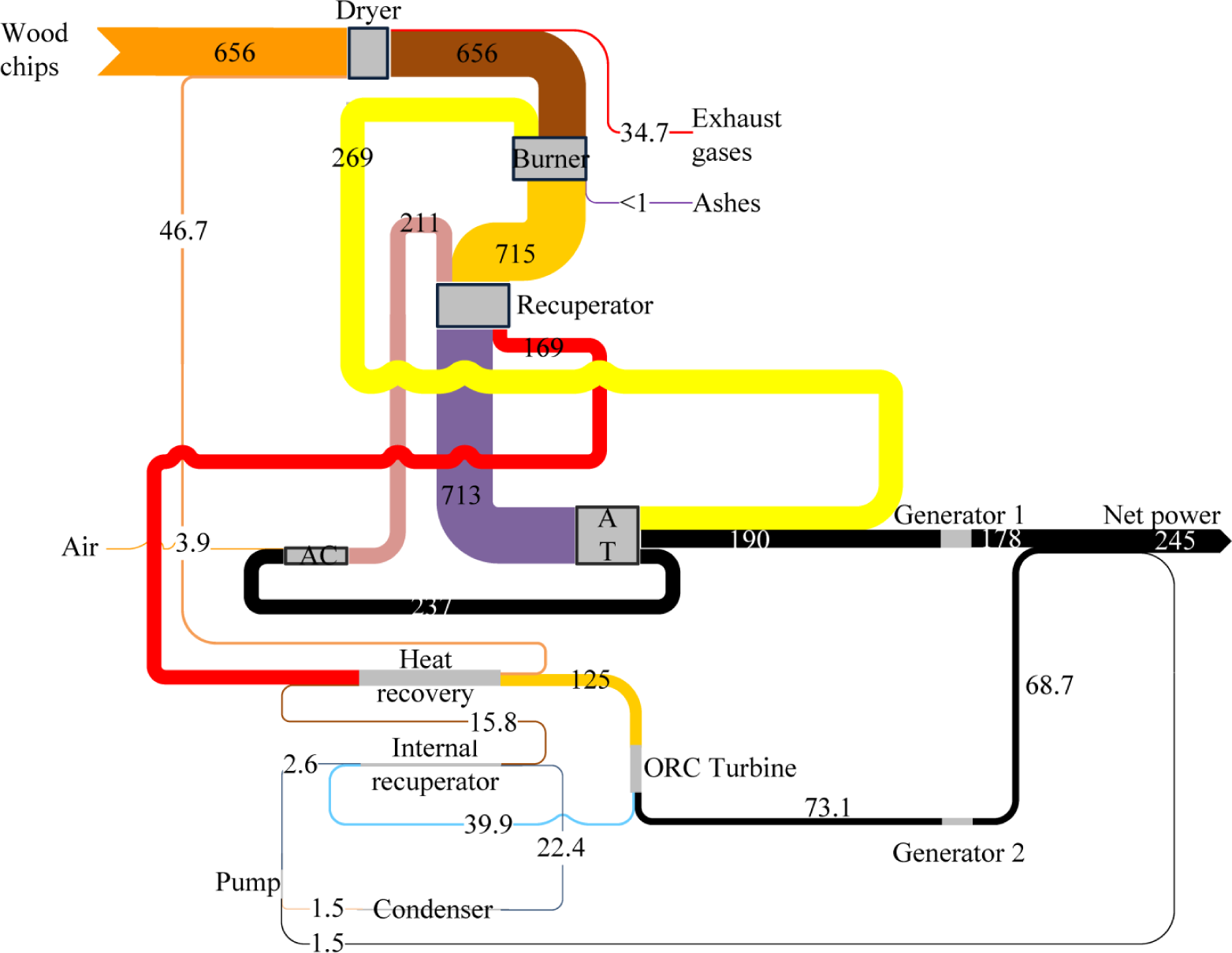
Figure 5 depicts the Grassmann diagram of the optimal plant design. The overall thermal efficiency, defined by replacing the denominator in Equation (3) with the product of the mass flow and the lower heating value of the woodchips, is equal to 43.0%. The net power outputs (exergy products) of the gas turbine unit and of the ORC power module are around 180 kW and 70 kW, while the total exergy destruction amounts to 380 kW. The most significant exergy depletions occur in the burner (55.4%), recuperator (11.4%), AC (8.0%) and in the condenser (5.5%). The other contributions are negligible, accounting for less than 5.0% each. The high exergy destruction in the burner is caused by: (i) the irreversibilities of the combustion reactions, which are inefficient in essence; and (ii) the mixing of reactants with different chemical compositions. The other major irreversibilities originate from the heat transfer across the large temperature gap between the hot gases (1000 °C) and the compressed air (230 °C) in the recuperator, the inefficiencies of the compressor, and from the large amount of heat wasted to the environment by the condenser.
The two components that display the greatest exergy destruction, i.e., the burner and the recuperator, have a high exergetic efficiency of 77.3% and 92.1%, respectively. This apparent paradox can be explained by the large quantities of exergy flowing through these components. The ORC condenser, pump and internal recuperator display the lowest exergy efficiencies, with values of 0%, 73.5% and 75.2%, respectively. The condenser is a purely dissipative component, as exergy is discharged to the environment without any practical use. The causes for the low efficiencies of the internal recuperator and of the pump are the same as for the recuperator and compressor of the topping cycle. The exergy destruction in the ORC equipment (55 kW) is moderate compared with that of the gas turbine module (325 kW). This trend has two major causes: (i) the exergy flow of the working fluid is much smaller than those of the air and woodchips; and (ii) no chemical reaction, typically associated with large exergy destructions, takes place in the ORC turbogenerator. The same trends are observed for all working fluids investigated in this work, with an exergy destruction of 55%–68% for the burner, 5%–20% for the recuperator, 4%–6.5% for the AC and 3%–5% for the dryer.
Exergy losses amount to 35.0 kW in total, with a split of 34.7 kW for the exhaust gases and 0.3 kW for the ash. The exergy losses associated with the discharged ash are negligible, while the ones with exhaust gases range between 4.5% and 6.5% of the total exergy input of the plant.
4.2. Part-Load Performance
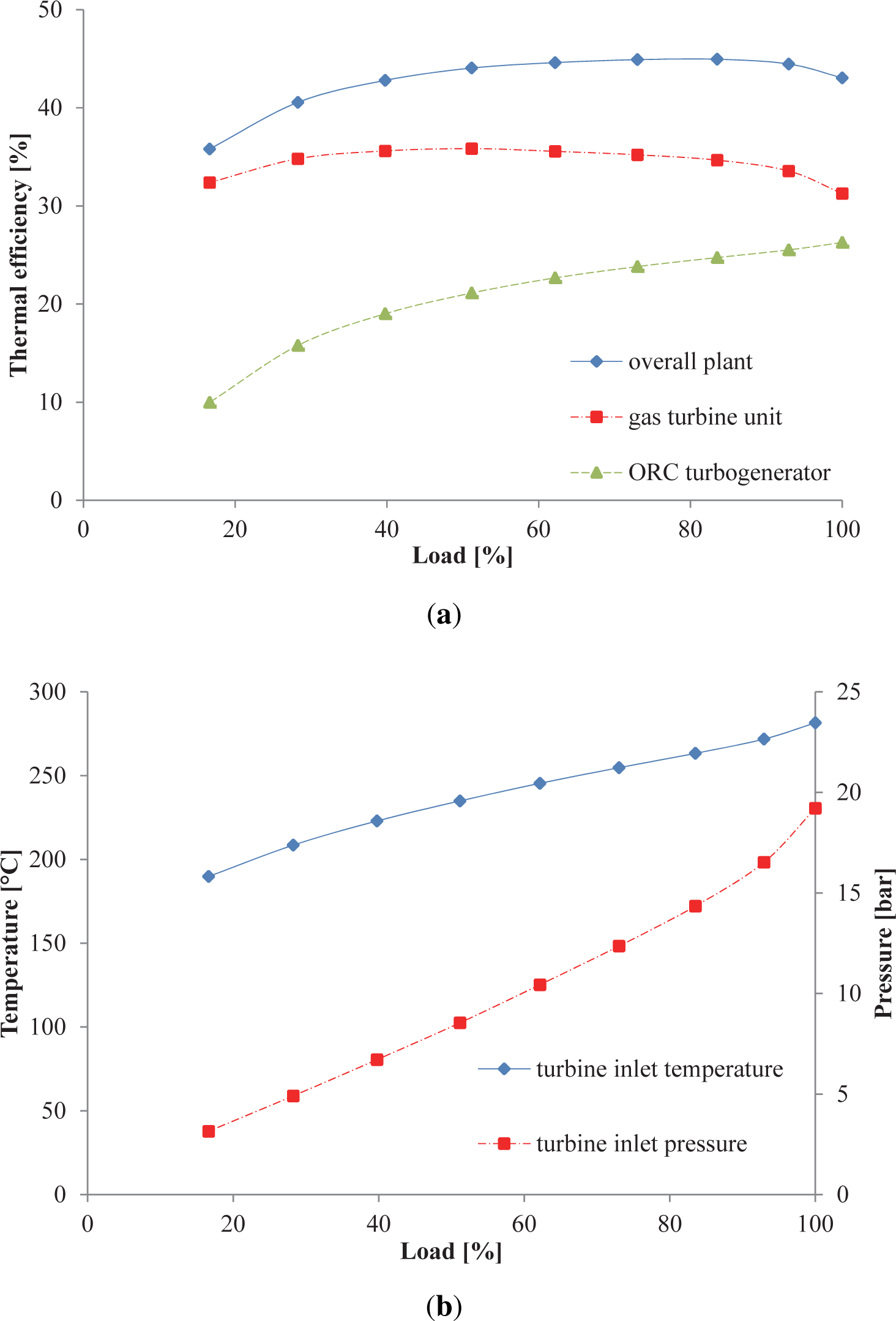
The exergy analysis performed in Section 4.1 enables to select the design-point pressure ratio (5.5) of the centrifugal compressor, the working fluid (toluene) and the turbine inlet pressure of the ORC unit (20 bar). Having defined the required off-design parameters, e.g., the volume flow rates in Equation (A5), promptly computable from the optimal design-point configuration, the part-load characteristics of the plant can be derived. Figure 6(a) reports the thermal efficiency of the entire plant and of the gas turbine unit and the ORC turbogenerator as a function of the total load expressed as a percentage of the nominal capacity. The gas turbine package presents an average thermal efficiency of around 34.0% with a peak of 35.8% at 50% load, whereas the thermal efficiency of the ORC unit falls monotonically from 26.2% to 10.0% for decreasing loads. Accordingly, the plant performance first rises to 45.0% at around 80% load and subsequently declines to a minimum of 35.8%. Figure 6(b) indicates that operations in sliding-pressure mode entail a reduction of 15 bar in the pressure at the inlet of the ORC expander, moving from 100% to 15% power outputs. For the same load variation, the maximum temperature of the ORC t6 drops from 260 °C to 200 °C.
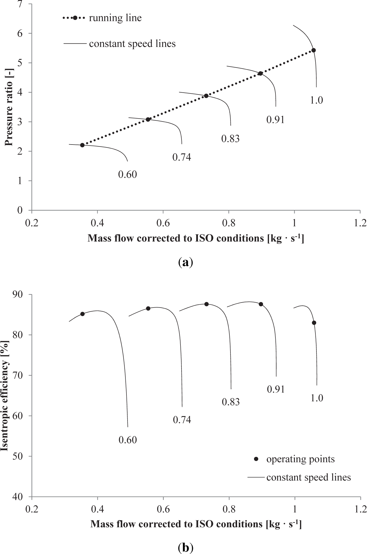
Figure 7(a) and 7(b) illustrates the maps and the corresponding running line of the centrifugal compressor for five loads (100%, 83.5%, 62.1%, 39.7%, 16.9%), which correspond to the constant speed lines drawn in the plots. At part-load conditions the biomass input decreases, while the set-point of the combustion temperature is maintained equal to 1000 °C. Thereafter, the control system reduces the air flow rate and the pressure ratio delivered by the AC, by lowering the rotational speed of the shaft, see Figure 7(a). The compressor performance remains close to the design-point value in all off-design conditions with a maximum isentropic efficiency of 87.6% at 60% load, see Figure 7(b).
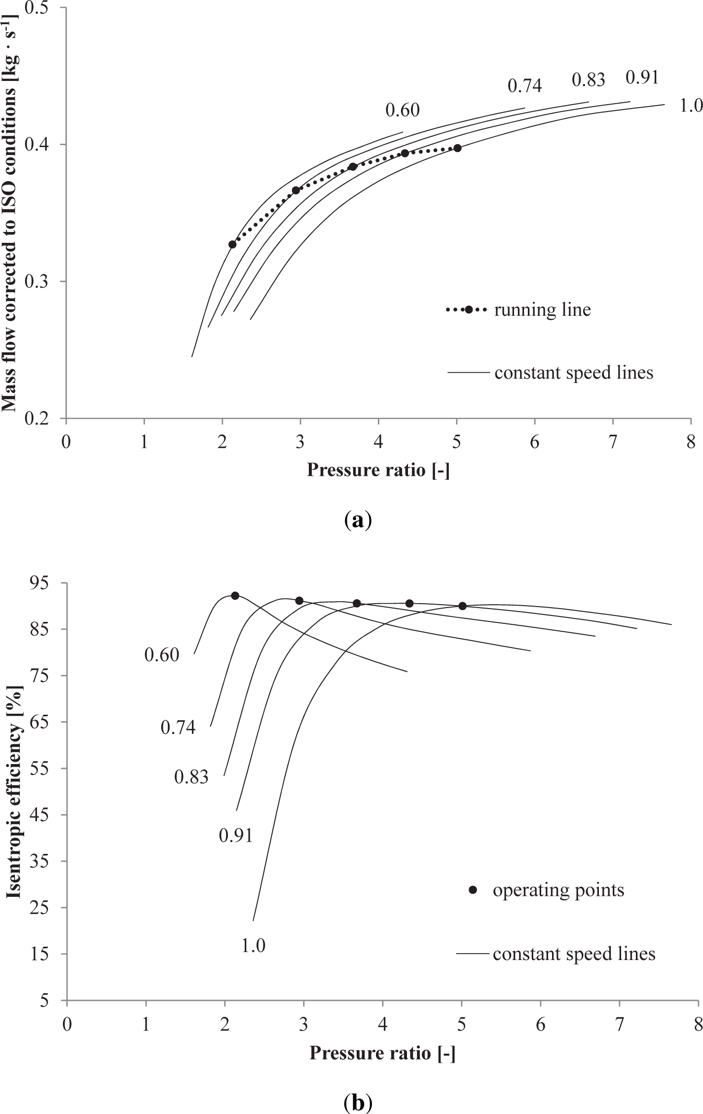
Figure 8(a) and 8(b) illustrates the maps and the corresponding running line of the radial turbine mechanically coupled to the centrifugal compressor. Given a reduction of the power output from 100% to 15%, the corrected mass flow drops from 0.40 kg · s−1 to 0.32 kg · s−1, while the turbine isentropic efficiency augments from 90.0% to 92.2%.
5. Discussion
Invernizzi et al. [13] proposed a first attempt to integrate an IFGT with an ORC power module. With a combustion temperature of 700 °C, the estimated thermal efficiency was around 20%. In this regard, simulations provide evidence that the novel plant configuration proposed in this study can theoretically attain thermal efficiencies between 30% and 43% for operating temperature of the burner ranging from 700 °C to 1000 °C. The higher system performances are due to the innovative features introduced in the system layout, see Figure 1. Compared with the original configuration proposed by Invernizzi et al. [13], the ORC unit is not powered directly by the heat contained in the air exiting the gas turbine module. After the expansion process, the air acts in fact as oxidant in the combustion process. Subsequently, the stream of products is cooled in the recuperator and it finally supplies the ORC turbogenerator. Furthermore, introducing a dryer enables to extend the fuel flexibility of the plant to biomasses with large moisture contents. The drying process takes place by utilizing the heat contained in the exhaust gas flow exiting the superheater. This technique improves further the plant performances by decreasing the exhaust temperature of the gases released to the environment. Despite the difference in the proposed plant layouts, the selection of the optimal working fluid for the ORC turbogenerator is in accordance with the results reported in Invernizzi et al. [13]. Table 1 indicates that all the organic compounds considered in this study present a relatively high flammability and toxicity. However, ORC units employing toluene and pentane are currently under operation and available on the market [37]. Furthermore, novel waste heat recovery systems based on the ORC technology using cyclopentane as working fluid have been recently produced, see Del Turco et al. [25]. These examples suggest that obstacles related to the risk of fire and explosion, for instance when using toluene, have already been overcome by manufacturers of organic Rankine engines.
As for the exergy analysis, findings indicate that the exergy destruction and losses taking place in the ORC unit are moderate, suggesting that efforts to improve the system performance should be focused on the gas turbine side. As in previous works on IFGTs (see for example Datta et al. [11]), the thermodynamic irreversibilities occur primarily in the burner and in the recuperator. Higher combustion temperatures could result in smaller exergy destruction for the whole system. On the other hand, plant activities of the biomass burner at temperatures exceeding 1100 °C are impeded by high thermal stresses in the ferritic alloys of the recuperator. Moreover, this temperature level increases the probability of fuel ash sintering, see Gaderer et al. [38]. While the exergy destruction in the burner can hardly be reduced owing to the irreversible nature of combustion processes, an improved matching of the biomass feed and compressed air temperatures may abate the exergy destruction due to mixing. Preheating of woodchips prior to the burner may lead to a higher performance of this component. The same reasoning applies to the recuperator, where the exergy destruction results from the temperature difference between the hot and cold sources.
The off-design investigation suggests that the plant efficiency remains higher than 43.0% down to 50% load, with a peak of 45.0% at around 80% load. Given a reduction of the load set-point, the rectifier-inverter system tracks the temperature of the combustion products by lowering the rotational speed of the gas turbine shaft. This action entails a decrease of the pressure ratio and mass flow intake by the centrifugal compressor, while the temperature at the inlet of the radial turbine remains nearly unvaried. As a result, the mass flow rate of the combustion gases powering the ORC module is also reduced. With the selected operational mode, i.e., saturated vapor condition at the outlet of the preheater-evaporator, and given the characteristics curves of the components, the mass flow rate and the temperature and pressure at the inlet of the ORC expander decrease. The trend of these process variables agrees qualitatively with the findings reported by Lee and Kim [39] for a microturbine ORC power system fired by natural gas. While the performance of the ORC turbogenerator decreases monotonically with the load, the efficiency of the gas turbine package peaks at 50% load (refer to Figure 6(a)). As indicated in Figures 7(b) and 8(b), the centrifugal compressor and the radial turbine exhibit the largest isentropic efficiencies at off-design conditions, thus justifying the efficiency trend of the gas turbine unit. On the other hand, the drops of the temperature and pressure at the inlet of the ORC expander penalizes the performance of the unit, especially at low-power activities, by virtue of the lower thermodynamic mean temperature of the cycle. Moreover, the efficiency drops of the pump and electric generators contribute to a further reduction of the overall system performance, the decrement being particularly significant at low loads (15%–30%). Analogous curves relating the thermal efficiency of the ORC unit to the plant net power are reported by Gurgenci [40] for an ORC engine fed by hot brine at 85 °C with a net power output of 150 kW.
As regarding the uncertainties in the results, operational data of the ORC system are required to properly quantify the accuracy of the adopted off-design methods. Given the lack of publicly available data and considering the particular system layout and control strategy proposed here, an in-depth validation is currently beyond the possibilities of the present work. Nonetheless, the model of the ORC system is based on the methods used to model a 150 kW ORC system using toluene as the working fluid, and successfully validated for steady-state (and transient) operation against experimental data as discussed in Casella et al. [41]. The model of the bottoming cycle unit is, therefore, deemed reliable, considering the similarity of the application at hand with the one presented in the cited reference. It is also worth mentioning that the part-load results of the AT and centrifugal compressor largely depend on how close the original maps, utilized to find the reference point, are to the compressor under investigation. In fact, an appropriate selection of the reference point is essential for increasing the model precision [29]. In this regard, the original maps utilized in this work operate in similar ranges of pressure ratios (2–6) and mass flow rates (0.3–1.1 kg · s−1), compared with the turbomachinery designed here. Note also that the reference point to scale the map was set in accordance with the guidelines proposed by Kurzke [29].
Table 3 lists the size, thermal efficiency and the specific cost of available and future technologies for the conversion of biomass into electric power. The optimized plant proposed in this study doubles the thermal efficiency of standalone IFGT and Stirling engines. Improvements around 8%- and 15%-points are achieved compared with single- and double-stage ORC power modules. However, the theoretical performance of the plant is lower than that of technologies integrating gasification, SOFCs and bottoming cycle units. Assuming a specific cost of 6,248 € · kW−1 [3] for the gas turbine package and of 4,900 € · kW−1 [42] for the ORC turbogenerator, the plant investment can be estimated to be around 6,000 € · kW−1. While this value is lower than that of Stirling motors, gas engines and IFGTs, the system exhibits a higher investment cost compared with IGCC plants. The use of IGCCs fired by biomass achieves thermal efficiencies comparable to the plant studied in this work. However, its application is typically directed to power outputs larger than 10 MW. On the other hand, a significant reduction of the production cost of the gas turbine package appears necessary in order to enhance the economic feasibility of the plant presented here, and to make its initial investment cost comparable to that of ORC units.
6. Conclusions
The design- and part-load performance of an innovative plant consisting of a WIFGT fueled by woodchips and an ORC were investigated. The results suggest that with a combustion temperature of 1000 °C, the optimal compressor pressure ratio is 5.5. The working fluid in the ORC unit designated among five alternatives is toluene. Given the configuration of the ORC expander, i.e., a two-stage axial turbine, the evaporation pressure is limited to 20 bar so as to ensure high isentropic efficiencies at the design-point load.
The exergy analysis suggests that the addition of the ORC power module in the layout of the system improves the exergy efficiency by around 12%-points compared with a standalone WIFGT. The largest exergy depletions are located in the burner (55.4%), recuperator (11.4%), AC (8.0%) and condenser (5.5%). It can be concluded that efforts to improve the performance of the plant should focus on the gas turbine package rather than on the ORC unit. This analysis also pinpoints the presence of a strong interdependency between the optimal pressure ratio of the centrifugal compressor and the organic compound circulating in the ORC power module.
By operating the burner at a constant combustion temperature and the ORC turbogenerator in sliding-pressure mode, the plant can maintain a high performance (>35%) even at low-power activities. The maximum isentropic efficiencies of the centrifugal compressor and the radial turbine occur in off-design operations. Accordingly, the overall thermal efficiency of the plant peaks at around 80% reaching a value of 45%. Subsequently, decreasing the load deteriorates progressively the plant performance by virtue of the lower efficiency of the ORC turbogenerator and of the auxiliary equipment, i.e., the pump and the electric generators.
Author Contributions
Leonardo Pierobon is the principle investigator of this work. Tuong-Van Nguyen performed the exergy analysis of the innovative power plant, while Andrea Mazzucco contributed with a preliminary evaluation of the economic feasibility of the system. Final review was done by Ulrik Larsen and Fredrik Haglind.
Conflicts of Interest
The authors declare no conflict of interest.
| Nomenclature | |
|---|---|
| A | Area (m2) |
| F | Factor in Equation (A6) |
| Fcu | Copper loss fraction |
| Load | Electric generator load |
| N | Rotational speed (rpm) |
| T | Temperature (K) |
| U | Heat transfer coefficient (kW · m−2 · K−1) |
| Ė | Exergy flow (kW) |
Volumetric flow rate (m3 · s−1) | |
Mass flow (kg · s−1) | |
| c | Speed of sound (m · s−1) |
| e | Specific exergy (kJ · kg−1) |
| h | Specific enthalpy (kJ · kg−1) |
| k | Summation index |
| p | Pressure (bar) |
| s | Specific entropy (kJ · K−1 · kg−1) |
| Abbreviations | |
|---|---|
| AC | Air compressor |
| AT | Air turbine |
| DNA | Dynamic network analysis |
| FH, HH, PH | Fire, health and physical hazard |
| GEN | Electric generator |
| GWP | Global warming potential |
| IDA | Danish association of engineers |
| IFGT | Indirectly fired gas turbine |
| IGCCs | Integrated gasification combined cycles |
| ISO | International organization for standardization |
| ODP | Ozone depletion potential |
| ORC | Organic Rankine cycle |
| OT | Organic Rankine cycle turbine |
| SOFC | Solid oxide fuel cell |
| WIFGT | Wet indirectly fired gas turbine |
| Greek Letters | |
|---|---|
| Δ | Difference |
| γ | Exponent in Equation (A4) |
| ρ | Density (kg · m−3) |
| η | Efficiency |
| Subscripts | |
|---|---|
| d | Destruction |
| des | Design |
| el | Electric |
| is | Isentropic |
| Q | Heat |
| S | Thermodynamic static state |
| T | Thermodynamic total state |
| th | Throat |
| W | Work |
Appendix
A. Part-Load Models
This appendix reports the steady-state equations utilized to assess the part-load performance of the components constituting the WIFGT and the ORC turbogenerator. As for the models of the centrifugal compressor and the radial expander serving the IFGT, the reader is referred to the procedure outlined in Kurzke [29].
OT:
In the system of Equation (A1), h6 and s6 are the specific enthalpy and entropy at the turbine inlet, and the subscript “S,th” indicates static conditions in the throat section. The continuity equation relates the mass flow rate through the nozzle to the density pS,th and the flow passage area Ath in the throat section. Isentropic expansion is assumed from the inlet section, where total conditions (i.e., total pressure pT,6 and total temperature TT,6) are assumed to be known by virtue of the thermodynamic state calculation, to the throat, where sonic conditions are attained, i.e., the flow speed equals the speed of sound c. By solving the system of Equation (A1) for a given design-point condition (i.e., the thermodynamic state and mass flow rate at the turbine inlet), the total nozzle throat area Ath can be evaluated. In Equation (A2) proposed by Schobeiri [32], the isentropic efficiency ηis is given as a function of the rotational speed N in rpm and the isentropic enthalpy drop ∆his in kJ · kg−1. The subscripts “des” and “off” refer to the variables calculated at design-point and off-design, respectively.
Electric generators (Haglind and Elmegaard [34]):
where ηel is the electric efficiency of the generator, Load is the mechanical power input in per unit and Fcu is the copper loss fraction, which is assumed to be equal to 0.43 [34].Heat exchangers (Incropera et al. [31]):
where U is the heat transfer coefficient. The exponent γ is taken equal to 0.6 [31]. In Equation (A5), the variables and ∆p are the volumetric flow rate and the pressure drop inside (outside) the tubes.Pumps (Veres [33]):
where ηp is the pump isentropic efficiency.
References
- Council of the European Union. Presidency Conclusions of Brussels European Council, 2007. Available online: http://www.consilium.europa.eu/ueDocs/cms_Data/docs/pressData/en/ec/93135.pdf accessed on 13 October 2014.
- Lund, H.; Mathiesen, B.V. Energy system analysis of 100% renewable energy systems—The case of Denmark in years 2030 and 2050. Energy 2009, 34, 524–531. [Google Scholar]
- Wood, S.; Rowley, P. A techno-economic analysis of small-scale, biomass-fuelled combined heat and power for community housing. Biomass Bioenergy 2011, 35, 3849–3858. [Google Scholar]
- Ahrenfeldt, J.; Henriksen, U.; Jensen, T.K.; Gøbel, B.; Wiese, L.; Kather, A.; Egsgaard, H. Validation of a continuous combined heat and power (CHP) operation of a two-stage biomass gasifier. Energy Fuels 2006, 20, 2672–2680. [Google Scholar]
- Drescher, U.; Brüggemann, D. Fluid selection for the Organic Rankine Cycle (ORC) in biomass power and heat plants. Appl. Therm. Eng 2007, 27, 223–228. [Google Scholar]
- Spliethoff, H. Power Generation from Solid Fuels; Springer: Berlin, Germany, 2010. [Google Scholar]
- Bang-Møller, C.; Rokni, M.; Elmegaard, B. Exergy analysis and optimization of a biomass gasification, solid oxide fuel cell and micro gas turbine hybrid system. Energy 2011, 36, 4740–4752. [Google Scholar]
- Pierobon, L.; Rokni, M.; Larsen, U.; Haglind, F. Thermodynamic analysis of an integrated gasification solid oxide fuel cell plant combined with an organic Rankine cycle. Renew. Energy 2013, 60, 226–234. [Google Scholar]
- Kautz, M.; Hansen, U. The externally-fired gas-turbine (EFGT-Cycle) for decentralized use of biomass. Appl. Energy 2007, 84, 795–805. [Google Scholar]
- Bram, S.; de Ruyck, J.; Novak-Zdravkovic, A. Status of external firing of biomass in gas turbines. Proc. Inst. Mech. Eng. A 2005, 219, 137–145. [Google Scholar]
- Datta, A.; Ganguly, R.; Sarkar, L. Energy and exergy analyses of an externally fired gas turbine (EFGT) cycle integrated with biomass gasifier for distributed power generation. Energy 2010, 35, 341–350. [Google Scholar]
- Elmegaard, B.; Qvale, E.B.; Carapelli, G.; de Faveri Tron, P. Open-Cycle Indirectly Fired Gas Turbine for Wet Biomass Fuels, Proceedings of the Efficiency, Costs, Optimization, Simulation and Environmental Impact of Energy Systems, Istanbul, Turkey, 4–6 July 2001; pp. 361–367.
- Invernizzi, C.M.; Iora, P.; Sandrini, R. Biomass combined cycles based on externally fired gas turbines and organic Rankine expanders. Proc. Inst. Mech. Eng. A 2011, 225, 1066–1075. [Google Scholar]
- Cocco, D.; Palomba, C.; Puddu, P. Tecnologie Delle Energie Rinnovabili; Servizi Grafici Editoriali: Padova, Italy, 2008. (In Italian) [Google Scholar]
- Kays, W.M.; London, A.L. Compact Heat Exchangers; McGraw-Hill: New York, NY, USA, 1984. [Google Scholar]
- Klassen, H.A.; Wood, J.R.; Schumann, L.F. Experimental Performance of a 13.65-Centimeter-Tip-Diameter Tandem-Bladed Sweptback Centrifugal Compressor Designed for a Pressure Ratio of 6; National Aeronautics and Space Administration (NASA): Washington, DC, USA, 1977. [Google Scholar]
- Dixon, S.; Hall, C. Fluid Mechanics and Thermodynamics of Turbomachinery, 7th ed; Butterworth-Heinemann: Boston, MA, USA, 2014. [Google Scholar]
- Larjola, J. Electricity from industrial waste heat using high-speed organic Rankine cycle (ORC). Int. J. Prod. Econ 1995, 41, 227–235. [Google Scholar]
- Trapp, C.; Colonna, P. Efficiency improvement in precombustion CO2 removal units with a waste–heat recovery ORC power plant. J. Eng. Gas Turbines Power 2013, 135. [Google Scholar] [CrossRef]
- Paint, N.; Association, C. Hazardous Materials Identification System Implementation Manual; J. J. Keller & Associates, Inc.: Neenah, WI, USA, 2001. [Google Scholar]
- Forster, P.; Ramaswamy, V.; Artaxo, P.; Berntsen, T.; Betts, R.; Fahey, D.W.; Haywood, J.; Lean, J.; Lowe, D.C.; Myhre, G.; et al. Changes in Atmospheric Constituents and in Radiative Forcing; Cambridge University Press: Cambridge, UK, 2007; Chapter 2. [Google Scholar]
- Collins, W.; Derwent, R.; Johnson, C.; Stevenson, D. The oxidation of organic compounds in the troposphere and their global warming potentials. Clim. Chang 2002, 52, 453–479. [Google Scholar]
- Andersen, W.C.; Bruno, T.J. Rapid screening of fluids for chemical stability in organic Rankine cycle applications. Ind. Eng. Chem. Res 2005, 44, 5560–5566. [Google Scholar]
- Ginosar, D.M.; Petkovic, L.M.; Guillen, D.P. Thermal stability of cyclopentane as an organic Rankine cycle working fluid. Energy Fuels 2011, 25, 4138–4144. [Google Scholar]
- Del Turco, P.; Asti, A.; del Greco, A.; Bacci, A.; Landi, G.; Seghi, G. The ORegen™ waste heat recovery cycle: Reducing the CO2 footprint by means of overall cycle efficiency improvement, Proceedings of the ASME 2011 Turbo Expo: Turbine Technical Conference and Exposition, Vancouver, BC, Canada, 6–10 June 2011; 3, pp. 547–556.
- Perstrup, C. Analysis of Power Plant Installation Based on Network Theory. Master’s Thesis, Laboratory of Energetics, Technical University of Denmark, Kongens Lyngby, Denmark, 1991. [Google Scholar]
- Lemmon, E.W.; Huber, M.L.; McLinden, M.O. REFPROP: Reference fluid thermodynamic and transport properties; NIST Standard Reference Database 23; National Institute of Standards and Technology (NIST): Gaithersburg, MD, USA, 2013. [Google Scholar]
- Bejan, A.; Tsatsaronis, G.; Moran, M.J. Thermal Design and Optimization; John Wiley & Sons, Inc: Hoboken, NJ, USA, 1996. [Google Scholar]
- Kurzke, J. GasTurb Details 6 Manual—An Utility for GasTurb 12, 2014, Available online: http://www.gasturb.de/manual.html accessed on 13 October 2014.
- Pullen, K.; Baines, N.; Hill, S. The design and evaluation of a high pressure ratio radial turbine, Proceedings of the ASME Turbo Expo 1992, Cologne, Germany, 1–4 June 1992.
- Incropera, F.P.; DeWitt, D.P.; Bergman, T.L.; Lavine, A.S. Fundamentals of Heat and Mass Transfer, 6th ed; John Wiley & Sons, Inc: Jefferson City, MO, USA, 2007. [Google Scholar]
- Schobeiri, M. Turbomachinery Flow Physics and Dynamic Performance; Springer: Berlin, Germany, 2005. [Google Scholar]
- Veres, J.P. Centrifugal and Axial Pump Design and Off-Design Performance Prediction; NASA Technical Memorandum 106745; National Aeronautics and Space Administration (NASA): Sunnyvale, CA, USA, 1994. [Google Scholar]
- Haglind, F.; Elmegaard, B. Methodologies for predicting the part-load performance of aero-derivative gas turbines. Energy 2009, 34, 1484–1492. [Google Scholar]
- Campanari, S. Full load and part-load performance prediction for integrated SOFC and microturbine systems. J. Eng. Gas Turbines Power 2000, 122, 239–246. [Google Scholar]
- Macchi, E.; Perdichizzi, A. Efficiency prediction for axial-flow turbines operating with nonconventional fluids. J. Eng. Gas Turbine Power 1981, 103, 718–724. [Google Scholar]
- Quoilin, S.; Broek, M.V.D.; Declaye, S.; Dewallef, P.; Lemort, V. Techno-economic survey of Organic Rankine Cycle (ORC) systems. Renew. Sustain. Energy Rev 2013, 22, 168–186. [Google Scholar]
- Gaderer, M.; Gallmetzer, G.; Spliethoff, H. Biomass fired hot air gas turbine with fluidized bed combustion. Appl. Therm. Eng 2010, 30, 1594–1600. [Google Scholar]
- Lee, J.H.; Kim, T.S. Analysis of design and part load performance of micro gas turbine/organic Rankine cycle combined systems. J. Mech. Sci. Technol 2006, 20, 1502–1513. [Google Scholar]
- Gurgenci, H. Performance of power plants with organic Rankine cycles under part-load and off-design conditions. Sol. Energy 1986, 36, 45–51. [Google Scholar]
- Casella, F.; Mathijssen, T.; Colonna, P.; van Buijtenen, J. Dynamic modeling of organic Rankine cycle power systems. J. Eng. Gas Turbines Power 2013, 135. [Google Scholar] [CrossRef]
- Di Prima, M.; Santarossa, S. Modern ORC systems for sustainable use of wood biomass and waste heat, Proceedings of the 13th Energy Management Conference, Portoroz, Slovenia, 11–12 April 2011.
- Preißinger, M.; Heberle, F.; Brüggemann, D. Thermodynamic analysis of double-stage biomass fired Organic Rankine Cycle for micro-cogeneration. Int. J. Energy Res 2012, 36, 944–952. [Google Scholar]


| Parameter | Value | |
|---|---|---|
| Ambient temperature (°C) | 15 | |
| Ambient pressure (bar) | 1.0132 | |
| Woodchips mass flow (kg · h−1) | 180 | |
| Wood moisture content (%) | 33.6 | |
| Low heating value (dry) (MJ · kg−1) | 18.28 | |
| Combustion temperature (°C) | 1000 | |
| Burner pressure drop (%) | 2 | |
| Exhaust gas temperature (°C) | 110 | |
| Pressure drop heat exchangers (%) | 1 | |
| Efficiency of the electric generators (%)1 | 94 | |
| WIFGT | Compressor isentropic efficiency (%) | 83 |
| Compressor mechanical efficiency (%) | 97 | |
| Recuperator pinch point (°C) | 100 | |
| Turbine isentropic efficiency (%) | 90 | |
| ORC unit | Pump isentropic efficiency (%) | 70 |
| Turbine isentropic efficiency (%) | 80 | |
| Preheater-evaporator pinch point (°C) | 15 | |
| ORC recuperator pinch point (°C) | 25 | |
| Condenser outlet temperature (°C) | 50 | |
1The item includes also the power losses of the rectifier-inverter system.
| Fluid | HH/FH/PH1 | GWP2 | ODP | Tc (K) | pc (bar) | Mc (g · mol−1) |
|---|---|---|---|---|---|---|
| Cyclopentane | 2/3/0 | ≈3.0 | 0 | 511.7 | 45.7 | 70.1 |
| Pentane | 2/4/0 | <3.0 | 0 | 469.7 | 33.7 | 72.1 |
| Isopentane | 1/4/0 | <3.0 | 0 | 460.3 | 33.7 | 72.1 |
| Benzene | 2/3/0 | <2.6 | 0 | 562.0 | 49.0 | 78.1 |
| Toluene | 2/3/0 | ≈3.3 | 0 | 591.7 | 41.2 | 92.1 |
1Hazard classification based on the hazardous materials identification system (HMIS) developed by the American coatings association [20]. HH = health hazard, FH = fire hazard, and PH = physical hazard2GWP over a period of 100 years.
| System | Size (kW) | ηth (%) | Cost (€ · kW−1) |
|---|---|---|---|
| IFGT [3] | 100 | 20.0 | 6,248 |
| Stirling engine [3] | 35 | 12.0–18.0 | 7,140 |
| ORC unit [42] | - | 25.3 | 4,900 |
| Double-stage ORC unit [43] | 201 | 34.8 | - |
| Gasification & gas engine [3] | 2501 | 25.0 | 5,355 |
| Gasification & combined cycle [6] | 20 × 103 | 45.0 | 3,000 |
| Gasification & SOFC & gas turbine [7] | 274.5 | 55.0 | - |
| Gasification & SOFC & ORC [8] | 120 | 56.4 | - |
| WIFGT & ORC | 250 | 43.0 | 6,000 |
1The value refers to the heat rate (or thermal power) input of the plant.
© 2014 by the authors; licensee MDPI, Basel, Switzerland This article is an open access article distributed under the terms and conditions of the Creative Commons Attribution license (http://creativecommons.org/licenses/by/4.0/).
Share and Cite
Pierobon, L.; Nguyen, T.-V.; Mazzucco, A.; Larsen, U.; Haglind, F. Part-Load Performance of aWet Indirectly Fired Gas Turbine Integrated with an Organic Rankine Cycle Turbogenerator. Energies 2014, 7, 8294-8316. https://doi.org/10.3390/en7128294
Pierobon L, Nguyen T-V, Mazzucco A, Larsen U, Haglind F. Part-Load Performance of aWet Indirectly Fired Gas Turbine Integrated with an Organic Rankine Cycle Turbogenerator. Energies. 2014; 7(12):8294-8316. https://doi.org/10.3390/en7128294
Chicago/Turabian StylePierobon, Leonardo, Tuong-Van Nguyen, Andrea Mazzucco, Ulrik Larsen, and Fredrik Haglind. 2014. "Part-Load Performance of aWet Indirectly Fired Gas Turbine Integrated with an Organic Rankine Cycle Turbogenerator" Energies 7, no. 12: 8294-8316. https://doi.org/10.3390/en7128294