1. Introduction
The potential uses for waste heat and other forms of low quality energy produced during power production have been investigated for decades, but low fuel prices and high equipment costs have made these solutions economically unattractive. One of the primary reasons for the high cost of power production using low temperature sources is the low available efficiency, which is typically 10% or lower.
However, emissions have become very important on the global scale. Exhaust emissions originating from land transport and electricity generation are already strongly restricted, resulting in considerably reduced emissions. Worldwide shipping consumes 5% of the total oil consumed [
1,
2], which amounts to global NO
x emission of approximately 12.57 Mt/y and global SO
x emission of approximately 10.54 Mt/y [
1].
The Kyoto Protocol concerning “greenhouse gases” (mainly CO
2) came into effect on 16 February 2005. According to the International Maritime Organization (IMO), shipping generates some 438 Mt/y of CO
2 worldwide, which corresponds to approximately 1.8% of global CO
2 emissions [
3]. Despite its large contribution to global emissions, shipping generates the least emissions per t/km during freight transport, which is less than other sorts of transport.
Low-speed two-stroke turbocharged diesel engines are the most commonly used marine propulsion engines today. These engines use low grade heavy fuels; they are the most efficient engines, exhibiting 50% efficiency. Therefore, the specific fuel consumption and CO2 emissions are relatively low, but decreasing fuel consumption and emissions including CO2 emission, remains an ongoing goal.
Further increases in the maximum cylinder pressure do not yield significant increases in efficiency, so it is unrealistic to expect that emissions can be reduced in this way. The majority of the waste heat from the main engine is contained in the exhaust gases after the turbocharger (T/C). The temperatures are relatively low, yet still high enough to feed an exhaust gas boiler and produce the steam necessary to heat the ship. The waste heat contained in air, lube oil and water jacket coolers features roughly the same properties as the heat in the exhaust gases, but the temperatures are even lower.
In the late 1980s, the manufacturers of low-speed diesel engines tried to utilise the surplus heat energy from the exhaust gases by fitting turbo-compound systems. Through the powered gas turbine, the turbo-compound system produced additional power that was mechanically transmitted to the propeller shaft, increasing the power output and the main engine efficiency by 3%. That design was eventually abandoned when the leading manufacturers MAN-B&W Diesel A/S [
4] and WÄRTSILÄ Ltd. [
5] introduced new solutions based on injecting a higher portion of fuel with a shorter expansion and increasing the temperature of the exhaust gases, but reducing the engine efficiency. In these designs, the surplus exhaust gases bypass the turbochargers and are directed to a gas turbine to produce electricity. After passing through the power turbine and turbochargers all of the exhaust gases produce superheated steam in an exhaust gas-fired boiler. Expanding in the steam turbine which drive generator, the steam produces electric power. Commonly, both the gas turbine and the steam turbine drive the same generator. A portion of the steam with a lower temperature and pressure could be used to meet the heating needs of the ship. Most of the Waste Heat Recovery (WHR) systems have been delivered by P. Brotherhood, which is now owned by Dresser Rand; this company started WHR system production in 1990. After 2000, Mitsubishi Heavy Ind. Ltd has delivered over 100 WHR plants (in container ships and in crude oil tankers). Over the same period Shinko Ind. Ltd has delivered even more WHR plants (in Liquefied Natural Gas (LNG) carriers, in container ships and in crude oil carriers).
While employing diesel engine waste heat in the exhaust gases and cooling water, Aly [
6] calculated that a 15% to 16% increase of main engine power output could be achieved. Tien
et al. [
7] used diesel engine exhaust gas waste heat to produce steam to drive an electricity-producing turbine. The parameters including the mass flow rate of the waste gas, exhaust temperature and cooling water were accounted for. The heat recovery possibilities taken into account by Shu
et al. [
8] are turbocharger/power turbine, fresh water obtained by using multiple effect distillation or multi-stage flash desalination technology, electricity/power obtained from Rankine cycle, air conditioning and ice-making obtained by using sorption refrigeration and WHR systems. Their calculation of a basic compound WHR system with a turbocharger and a dual pressure multi-stage turbine obtained 2150 kW by steam turbine generator. Similar system in which part of exhaust gases bypassed turbocharger obtained 4000 kW by a steam generator. The best result was achieved introducing additional power turbine using bypass exhaust gases with total electricity of 5610 kW, which increased the overall efficiency by 8.03%. Butcher and Reddy [
9] investigated the influence of the gas composition, specific heat and pinch point temperature on the performance of a Heat Recovery Steam Generator (HRSG) and waste heat recovery-based power generation system using the second law. They found that the second law performance of the power generation system is very sensitive to the gas composition. The pinch point (PP) is a dominant parameter and should be selected carefully.
In this work, a new method for WHR was investigated to decrease the fuel consumption and emissions of ships and thus increase the efficiency of ship power plants. The first task was to choose a prime mover for electricity generation that uses low grade waste heat from the main ship engine. Numerous studies in the last decade showed that organic ORC is one of the most promising technologies for efficient utilisation of low grade waste heat [
10]. Moreover, a working fluid other than water is selected, and an optimal thermodynamic cycle is defined.
Working Fluids Other Than Water
If the saturated vapour line of the working fluid has a positive slope on the
T–s plot and the expansion begins with saturated or superheated vapour, the vapour must be superheated when leaving the expander. This state is particularly advantageous for turbines; the absence of a liquid leads to higher efficiencies relative to water steam, where the vapour normally leaves the turbine as wet vapour [
11]. However this design requires a desuperheater to remove the heat at higher temperatures before condensation. One efficient method uses most of the desuperheated vapour to preheat the liquid leaving the feed pump in a recuperative or regenerative heat exchanger [
12,
13]. Schuster
et al. [
14] found that the system efficiency should be maximised if the cycle approaches a triangular shape, while the live vapour temperature should be as high as possible; however, the isothermal heat transfer to the cycle should be as small as possible. This scenario could be realised under supercritical region conditions. Teng and Regner [
15] also suggested a WHR system with a supercritical cycle at the expense of increased pump work. The thermal efficiency of RC could be increased with superheating, but most organic fluids have low thermal instability temperatures, suffering chemical decomposition and deterioration at high temperatures and pressures. While the thermal stability of pure compounds may be estimated from molecules bond energies, the actual threshold temperature for traceable decomposition of working fluids is very much dependant on its surrounding environment [
16], on compatibility with other materials and on different plant operating conditions [
17]. Angelino and Invernizzi [
18] conducted experimental investigation on the thermal stability of some new zero ozone depletion potential (ODP) refrigerants. All the investigated fluids exhibit a variable, but excellent, thermal stability up to the following temperatures at which no decomposition was observable in 50–100 h: 425 °C for HFC-227ea, 400 °C for HFC-23 and HFC-236fa and 300 °C for HFC-245fa. Wang
et al. [
19] analysed the influence of the working fluid and operating conditions on the performance and net power output of an ORC for low grade heat utilisation. At a given condensing and evaporating temperature, fluids with low Jacob numbers performed well; specifically, fluids with a low specific heat and high latent vaporisation are preferable for use in an ORC. While studying of the engine energy [
20,
21] all possible residual heat sources are analysed separately considering their potential uses in different cycle configurations. The studied engine was 12 L two-stage turbocharged heavy duty diesel engine. The following heat sources were considered: the exhaust gas heat energy, the exhaust gas recirculation (EGR) cooler, the intercooler of the low pressure air outlet, the aftercooler where the high pressure air is cooled, and the engine block cooling water. This waste energy was used in water RC and a binary cycle with water and the R245fa working fluid. Another study utilising a RC applied on a diesel truck engine was performed by Katsanos
et al. [
22] using steam and R245ca. In both cases the brake specific fuel consumption at a 100% engine load was improved by 8.5% with R245ca and 7.5% with water. Mago
et al. [
23] investigated the performance of low temperature ORC’s with seven working fluids within three temperature ranges. The fluids with higher boiling points work comparatively better in ORC’s. Wang
et al. [
24] revealed that R11, R141b, R113 and R123 exhibit slightly better thermodynamic performances than the others, while R245fa and R245ca are the most suitable fluids. For high temperature ORC systems [
21,
25] R123, R365mfc and R141b are suggested. Larsen
et al. [
26] tested other non-flammable fluids, finding decafluorobutane with a global warming potential (GWP
100) of 7000, sulphur fluoride with a GWP
100 of 23,900 and nitrous oxide with a relatively low GWP
100 of 310. In conclusion, R245fa and 236ea are feasible choices with few hazards and near optimal efficiency at reasonable pressures, while the relatively high GWP represents an environmental drawback. Unfortunately, general lack of experimental tests of these two fluids in ORC application remains unverified in the actual power plants.
2. WHR System Modeling
Our work analysed a CHP process using a steam turbine for WHR, and as an addition ORC with R245fa fluid. In this study the steady state physical and thermodynamic equations were used, which is applicable during the ship voyage apart from during extremely heavy seas, bad weather conditions or manoeuvres. The thermodynamic states of all fluids, including air, exhaust gases, simple fuels, water, freons
etc., have been obtained using the National Institute of Standards and Technology (NIST) Refprop09 program [
27]. The observed marine cogeneration energetic system was discussed and analysed as a thermodynamic flow process, and was presented in schematic
h–s and
T–s diagrams. The temperature difference was checked at all levels.
Every ship requires electrical power for numerous machines and devices. Moreover, electric energy is required for normal crew life. Typically, a ship has three auxiliary diesel gensets with the same power, and one emergency genset with much less power. One diesel genset must supply enough electrical energy during navigation; it should meet additional requirements during manoeuvring. While loading and discharging cargo, the electrical energy consumption may increase significantly, requiring the second genset. Commonly, tankers featuring cargo pumps powered by electric motors have four auxiliary diesel gensets. In some cases, the cargo pumps may be driven by steam turbines.
For the purpose of results comparison data for Suezmax-sized oil tankers will be considered. Such a tanker has a peak electric demand of 780 kW during navigation. When cleaning the cargo tank during navigation, the total electrical energy demand reaches 935 kW. However, the experience of ship-owners proves that the electricity consumption is considerably smaller. Consequently, a 912 kWe diesel genset was selected for this ship.
It is common to heat the heavy fuel oil (HFO) and lube oil (LO) before separation, the HFO in feeder/booster module, the HFO tanks (service tanks, settling tanks, storage tanks), and the low grade sulphur (LGS) HFO tank. In addition, depending on season, heat must be provided for the crew. The steam used for various ship consumers is generated by a boiler. A common design features a composite boiler consisting of an oil-fired section and an exhaust gas section, both placed in the common shell. During navigation, the waste heat contained in the exhaust gases from the main engine is utilised to heat up water and generate steam for various ship consumers. In port, when the main engine is shut down, the oil fired section burns fuel to produce steam. The steam heat balance for Suezmax tanker for oil [
28] during navigation is shown in
Table 1 and
Table 2. The figures in the
Table 1 and
Table 2 correspond to the worse outside (winter) conditions.
Table 1.
Shipwide heat consumption during navigation for fuel and lube oil heating [
28].
Table 1.
Shipwide heat consumption during navigation for fuel and lube oil heating [28].
| Steam Heat Consumers | Consumed Energy (kW) | Steam Flow (kg/h) | FO or LO ΔT (°C) |
|---|
| HFO/DO separators | 52 | 90 | from 70 to 98 °C |
| Main Engine Lub Oil (ME LO) separator | 55 | 96 | from 40 to 90 °C |
| Auxiliary Engine (AE) LO separator | 16 | 28 | from 40 to 90 °C |
| ME/AE FO module | 196 | 342 | from 110 to 145 °C |
| HFO service tanks | – | – | 75 °C |
| HFO settling tanks | – | – | 75 °C |
| HFO storage tanks | 325 | 567 | 45 °C |
| Low Grade Sulphur (LGS) HFO storage | – | – | 45 °C |
Table 2.
Shipwide heat consumption for crew demands [
28].
Table 2.
Shipwide heat consumption for crew demands [28].
| Crew Demands | Consumed Energy (kW) | Steam Flow (kg/h) |
|---|
| Accommodation heating | 194 | 291 |
| Hot water | 34.5 | 87 |
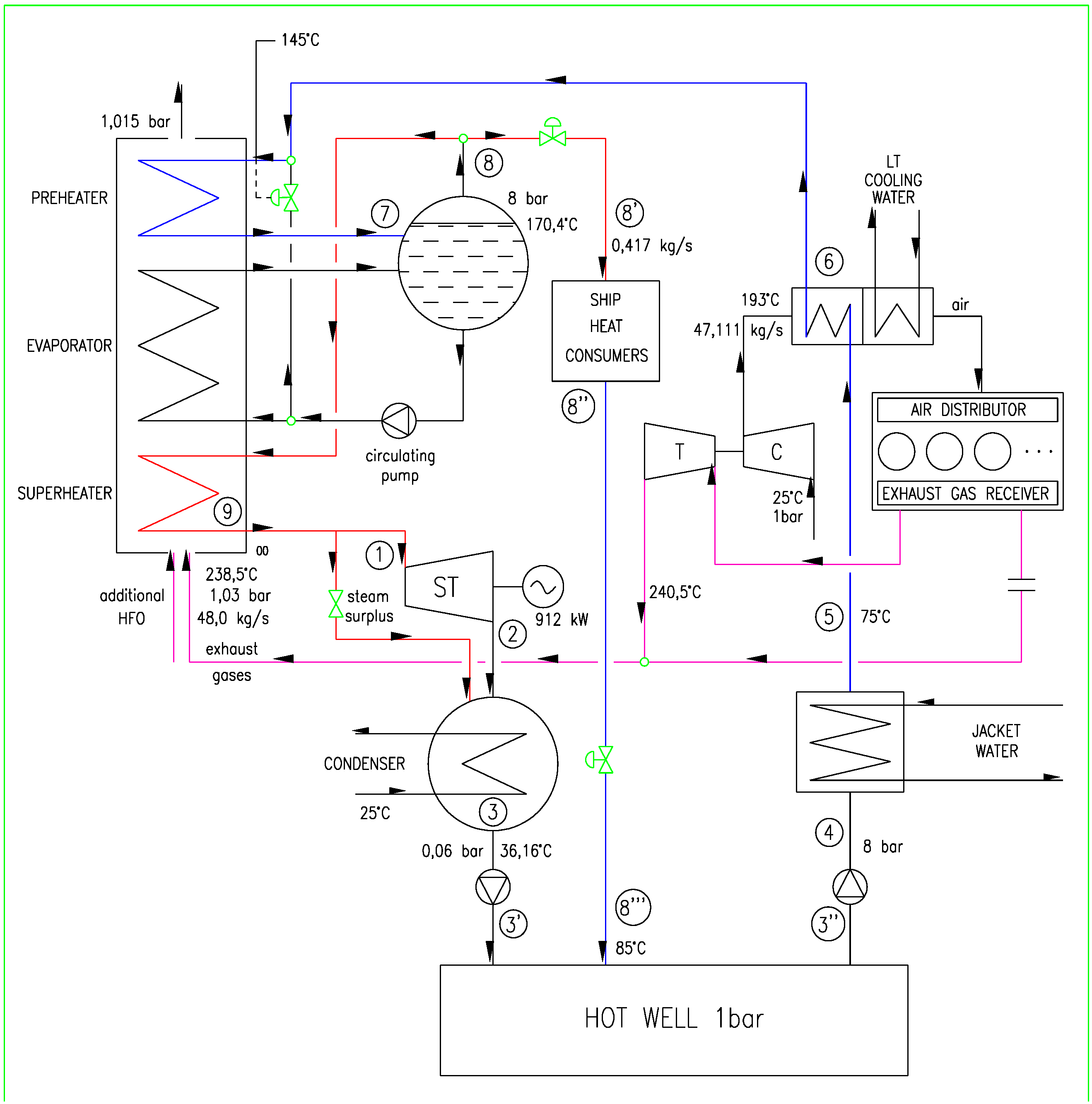
The total heat energy necessary for heat during navigation totals 872.5 kW, specifically 0.417 kg/s of saturated steam at 8 bars and 170.4 °C. This analysis involves the electric power produced by steam/vapour turbine and the heat produced for navigation purposes in the CHP plant with saturated steam or with the organic fluid. The CHP plant with the steam turbine (ST) and a water as the working fluid is shown in
Figure 1.
Figure 1.
Schematic diagram of the CHP plant with a steam Rankine cycle.
Figure 1.
Schematic diagram of the CHP plant with a steam Rankine cycle.
Because the temperature of the jacket cooling water is 83.5 °C, an adequate amount of heat is transferred to the working fluid in the heat exchanger. The scavenged air temperature is 164 °C at the normal continuous rating (NCR) or 193 °C at this specified maximum continuous rating (SMCR). This energy will also be employed. The largest amount of energy is contained in the exhaust gases.
The initial data refer to the standard ambient reference conditions according to the International Standard Organisation (ISO 3046) [
29]. The engine data; specific fuel consumption, temperature and mass flow rate of the exhaust gasses, jacket cooling water and scavenged air were acquired from the MAN engine room dimensioning software [
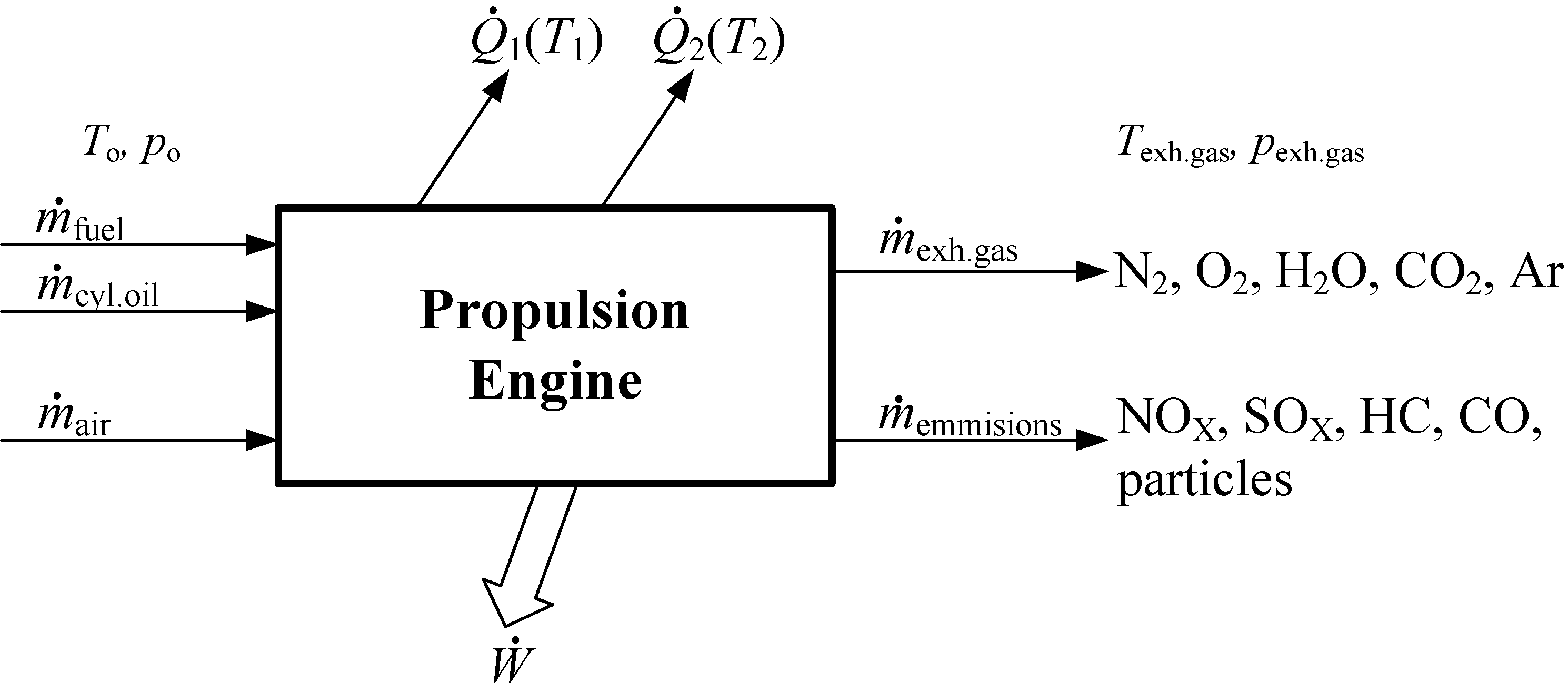
30] for 6S70MC-C7-T1 engine and the corresponding engine project guide. These values are not constant. The only constant value used is the information about exhaust emissions got from MAN data for similar engine. The composition of the exhaust gas was calculated using our own zero-dimensional model. The propulsion engine model depicting the main input and output variables, are shown in
Figure 2. It is assumed that fluid flow through propulsion engine is steady. The observer position is stationary with respect to the control volume surrounding the drive motor, in this case, the ship’s propulsion engine. In the simplest view, in the control volume the fuel and the air are entering, while combustion products, work
and heat
and
are taken away at different temperatures
T1 and
T2. For greater accuracy it is taken that the cylinder oil enters to control volume, and, with combustion products exit emissions as a small values of environmentally influential substance.
Figure 2.
The propulsion engine model depicting main input and output variables.
Figure 2.
The propulsion engine model depicting main input and output variables.
The engine is located in the environment temperature T0, in which the unused heat can be rejected. Environment, in this case, is the atmosphere, but the environment is also the cooling water from the sea or river. Environment can be considered as large enough when T0 does not change as a result of heat transfer. For proper operation of the engine it is necessary to lubricate all the parts that rub each against other, and this task is performed by lubricating oil. This oil takes part of the friction work and heat; heat carrier from the cylinder liner, cylinder cover, lubricating oil and scavenged air is the cooling water. In this paper is taken as the reference state of the environment the standard or ISO environmental state, where the temperature of the intake air and cooling water is 25.0 °C at 1.00 bar. At steady state conditions the continuity equation is .
The first law of thermodynamics can be expressed as conservation of energy in the control volume. Disregarding changes in potential and kinetic energy of the all substances flow, conservation of energy for steady state flow can be written as:
where
is the sum of flows inlet heat,
flow of taken (obtained) work,
and
are the mass flow rate and enthalpy of the individual flow substances. In Equation (1) as the form of the first law of thermodynamics, the work is technical. This means that it is done by moving the fluid with respect to the machine control volume, and not due to changes in volume of fluid that moves in relation to the control volume. Accordingly, below is
. Now:
Although the scavenged air consumption is taken from MAN B&W CEAS_ERD at ISO standard conditions, the composition of air is calculated by NIST using our initial values. Fuel composition for MDO and cylinder oil composition are taken in account, as well.
2.1. Working Fluid and Cycle Selection
Refrigerant fluids, such as R245fa (1,1,1,3,3-pentafluoropropane), are the most desirable fluids today. They are not flammable, but they cannot operate continuously at high temperatures due to degradation. Any thermal degradation implies the breaking of a number of molecules, which either form lighter substances or recombine in heavier compounds. In any case, the number of molecules in the system changes which implies, for a fluid in the gas state, a pressure variation at constant temperature and volume [
31]. According to Angelino and Invernizzi [
18] R245fa has excellent thermal stability up to 300 °C. According to Honeywell, decomposition of Genetron@245fa is over 250 °C [
32]. The critical temperature of R245fa is 154.01 °C at 36.51 bar. According to the American Society of Heating, Refrigerating and Air-Conditioning Engineers (ASHRAE) [
33] safety groups A1 and B1, flame does not spread through these fluids. Hydrocarbons such as toluene, pentane and isobutene are thermally stable at high temperature but are also flammable. Therefore, they cannot be used safely in WHR marine processes involving exhaust gas from propulsion engines; they require an intermediate fluid for heat transfer. In this study R245fa is chosen. As an alternative to R245fa the fluid R123 has been considered, some of its properties are shown in
Table 3 together with properties of R245fa and water.
Table 3.
Properties of R123, R245fa and water [
27].
Table 3.
Properties of R123, R245fa and water [27].
| Property | R123 | R245fa | Water |
|---|
| Chemical/structural formula | C2HCl2F3 | CHF2CH2CF3 | H2O |
| Molecular mass kg/kmol | 152.93 | 134.05 | 18.015 |
| Boiling point at 1.0133 bar | 27.82 °C | 15.140 °C | 99.976 °C |
| Density kg/m3 at 1.0133 bar | (L) 1456.6 (V) 6.4717 | (L) 1364.9 (V) 5.9619 | (L) 958.37 (V) 0.59768 |
| Enthalpy kJ/kg at 1.0133 bar | (L) 228.03 (V) 398.22 | (L) 219.51 (V) 415.55 | (L) 419.06 (V) 2675.5 |
| Critical point °C/bar | 183.68/36.618 | 154.01/36.51 | 373.95/220.64 |
| Atmospheric Life Time (ALT) | 1.3 y | 7.6 y | – |
| Ozone Depletion Potential (ODP) | 0.02 | 0 | – |
| GWP | 77 | 1030 | – |
| ASHRAE safety group | B1 | B1 | – |
An additional important criterion is the maximum cycle pressure. The latter should be chosen while accounting for the maximum temperature of engine exhaust gases and the temperature of jacket cooling water and scavenged air after the compressor (C) of turbocharger (T/C). In this paper, a supercritical cycle under 45 bar maximum pressure has been selected. Currently, steam turbine expanders ranging from a few kW up to 3 MW are used in ORC processes achieving high internal turbine efficiencies. Steam turbines over 0.5 MW in ORC achieve internal efficiencies near 85% [
34,
35], and isentropic turbine efficiency up to 90% is achievable in individual designs. Colonna
et al. [
36] stated that typical the isentropic efficiency design value is 87%. The efficiency is higher than that of a steam turbine because the maximum pressure and mass flow rate are much higher, while the expansion is completed within the superheated region.
According to [
37,
38], the advantages of turbines using organic fluids are the high cycle efficiencies, the very high internal turbine efficiency, the low mechanical stress of the turbine due to the low blade speed, the low turbine rotation speed enables direct generator drive, no blade erosion due to the absence of moisture during expansion, and a longer turbine life compared to steam turbines.
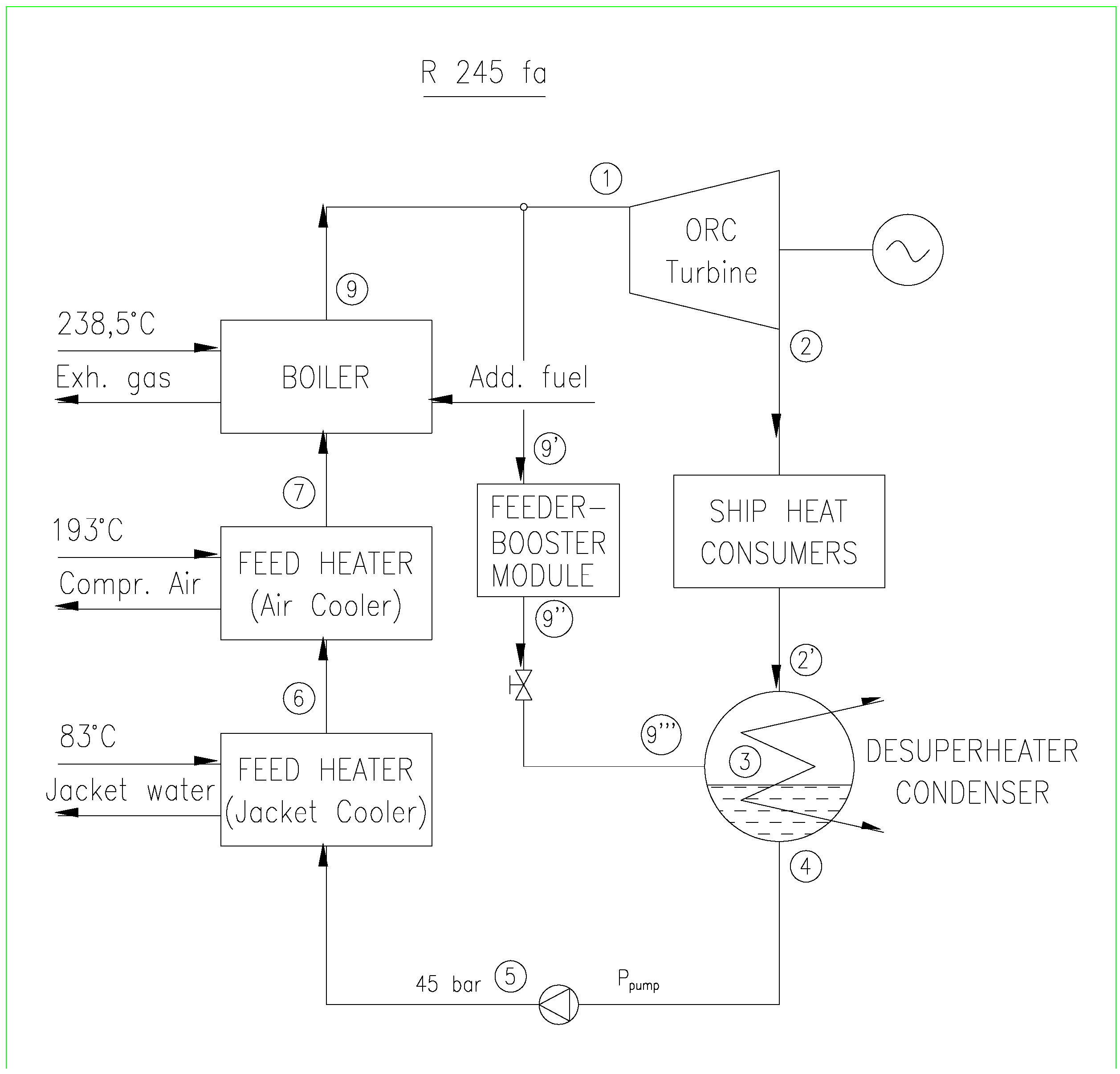
The further analysis addresses the possible cogenerative production of electrical energy and heat for ship requirements. The expander is a steam turbine with R245fa fluid in the CHP system. The steam turbine uses superheated R245fa vapour from the utilisation boiler; the boiler uses the exhaust gases from the main ship engine as a heat source through direct heating without an interfluid. The CHP plant with a turbine and R245fa as the working fluid is shown in
Figure 3.
Figure 3.
Schematic diagram of the CHP plant with the R245fa fluid.
Figure 3.
Schematic diagram of the CHP plant with the R245fa fluid.
2.2. Thermodynamic Analysis of the WHR Plant and the Calculation for a Vapour Turbine using R245fa as a Working Fluid for Full Electrical Power
In this paper, all computations follow the ISO standard conditions. The losses in fluid pressure are not considered except from between the boiler and the turbine. The computations have been made for the auxiliary engine using HFO. In the Emission Control Area (ECA), standard HFO is not acceptable; LGS HFO, marine DO or natural gas is used. In ECA 0.10% sulphur limit is coming into effect on 1 January 2015. That means using of low grade sulphur marine gas oil (LGSMGO) or natural gas as a ship fuel. As these fuels are more expensive (especially LGSMGO) than HFO, the potential financial savings are much higher [
39]. When using fuel with LGS, the exhaust gas temperature can fall below 145 °C.
Although the turbine using organic fluid rotates at a significantly lower speed compared to the steam turbine, no gearbox is needed in a real-life plant; the calculation includes the application of a gearbox on the shafting between the turbine and the generator. The calculation using steam as a working fluid was performed previously [
40] and has been repeated using R245fa in the supercritical vapour cycle. The ORC parameters should remain optimal or nearly so.
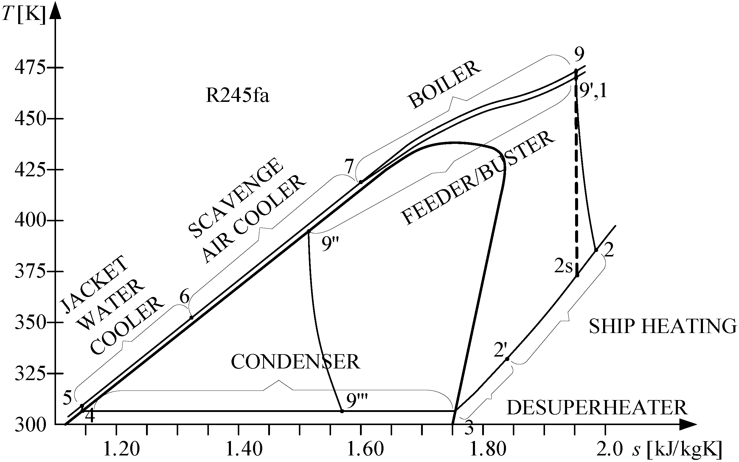
T–s diagram of the CHP plant with a turbine and R245fa as the working fluid is shown in
Figure 4.
Figure 4.
T–s diagram for the ORC CHP Plant with the R245fa fluid.
Figure 4.
T–s diagram for the ORC CHP Plant with the R245fa fluid.
Before starting with the calculations it was necessary to choose experiential values of some parameters as assumptions necessary for thermodynamic process analysis, shown in
Table 4.
Table 4.
Major assumptions for the thermodynamic analysis.
Table 4.
Major assumptions for the thermodynamic analysis.
| Parameter | Unit | Value |
|---|
| Turbine Isentropic Efficiency, ηi = ηTS | – | 0.85 |
| Turbine mechanical efficiency, ηm | – | 0.96 |
| Gearbox efficiency, ηGB | – | 0.95 |
| Generator efficiency, ηG | – | 0.97 |
| Pump isentropic efficiency, ηp | – | 0.85 |
| Pump mechanical efficiency, ηpm | – | 0.8 |
| Heat lost in the heat exchanger, hl | % | 1 |
| Heat lost in the HRSG, hl | % | 2 |
| Combustion efficiency of supplement fuel, ηb | – | 0.99 |
| HFO Lower heating value,
QLHVp | kJ/kg | 40,210 |
| Minimum exhaust gas temperature at HRSG outlet, T | °C | 145 |
| Pinch Point (PP) | °C | 15 |
| Working fluid pressure loss from HRGS to turbine, ploss | % | 5 |
| Working fluid temperature loss from HRGS to turbine, Tloss | °C | 3 |
| Power factor, cosφ | – | 0.8 |
| Full electric power during navigation for steam RC, PG | kW | 912 |
| Standard electric power during navigation for steam RC, PG | kW | 620 |
| Full electric power during navigation for ORC, PG1 | kW | 1015 |
| Standard electric power during navigation for ORC, PG1 | kW | 692 |
| Power plant working hours per year, th/y | h/y | 5,796.2 |
| The average price of HFO 380 cSt January 2012, CHFO | US$/t | 700 |
In accordance with the similar designs/power, η
m, η
GB, and η
G were selected. The internal turbine power and the internal efficiency are as follows:
The small difference in enthalpies and the power target justify the considerable amount of fluid in this cycle. However the fluid outlet state (
T2,
p2) still has a large specific volume (0.104097 m
3/kg). Therefore, fluid outlet speeds of
c2 = 40 to 60 m/s should be used. The outlet diameter of the pipeline towards the condenser can be estimated using the continuity equation:
In macroscopic form and control volume (
Vc):
For a steady state one dimensional flow:
Furthermore, the following are applicable:
Because the temperature of the working fluid after expansion in the turbine is 108.02 °C, the working fluid can be used for all of the heating needs on the ship except for heating the HFO in feeder/booster module before injection. To heat the HFO in the feeder/booster module it is necessary to heat an additional amount of the working fluid in the utilisation boiler. This additional working fluid is extracted before the turbine and transferred to the HFO heaters.
According to the data provided by the shipyard [
28], the fuel module consumes 196 kW of heat power when heating the HFO from 110 to 145 °C. The required heat power of the ORC fluid is as follows:
where
hl is the percentage of heat lost in the heat exchanger. Domingues
et al. [
41] investigated R245fa as an ORC working fluid for recovering heat from a combustion engine; the properties of R245fa promote the high effectiveness of the heat exchanger:
The working fluid (
Figure 3 and
Figure 4) enters the fuel module at 197 °C and leaves it at 120 °C (
Table 5), which is 10 °C higher than the initial temperature of the heated HFO. For the given temperatures and for
, the enthalpies
h9' and
h9'' can be obtained. Because the working fluid is throttled after heating the HFO inside the fuel module,
p2''' =
p2 and
h9'' =
h9'''.
The requirements of all other ship heat consumers during navigation are as follows:
By extracting the heat from the working fluid in process 2–2' (see
Figure 4) all of the heating requirements of the ship are met, except for that of the feeder/booster module.
The fluid at state 2' and the fluid at state 9''' enter the desuperheater/condenser where their heat is extracted to state 4, corresponding to saturated liquid. The feed ORC fluid from the condenser at the state point 4 is pumped up to 45 bar, reaching state point 5.
The feed-pump power is as follows:
Compared to the water-based process, the ORC requires a much larger feed pump due to the considerably larger mass flow rate of the organic fluid. The computation is repeated to calculate the power required for the generator and turbine:
The computation should be repeated to check the pump power and mass flow rate of the working fluid. When the heat energy of the working fluid is used to heat the HFO within the feeder/booster module, the mass flow rate and the temperature remain unchanged.
The total mass flow rate of the working fluid is as follows:
The computation should be repeated with the new generator and turbine power using Equations (13) and (21).
After the condenser, the working fluid is pumped to 45 bar and first heating is in the jacket water cooler. It is assumed that TORC,6 = 75 °C. At the start of iteration, it is assumed that jacket water outlet temperature is Tjacket,2 = 59.0 °C.
After being heated with the hot water from the cylinder jacket, the working fluid flows to the two-stage scavenged air heat exchanger. If the fluids do not change phase, the following is true:
The heat lost in the heat exchanger air/R245fa depends on cooling through insulation only, totalling approximately 1% with normal insulation design:
In the utilisation boiler, the working fluid should be heated from 150 to 200 °C at 45 bar (assuming that no working fluid pressure is lost through the boiler):
According to [
9] the heat lost in the HRSG is typically 2%–3%. The pinch point is assumed to be 15 °C while the minimal temperature at the boiler outlet is 145 °C. The exhaust gas temperature at the boiler outlet will vary from 165 to 145 °C because at temperatures below 145 °C, sulphuric acid may form/condense:
The surplus/shortage of energy in the exhaust gases totals the following:
In order to produce 912 kW/1015 kW of electrical energy, supplemental fuel is required for the exhaust gas boiler at some engine loads:
One of the main tasks of this work is calculation of the fuel consumption during an auxiliary Diesel genset acceptance test:
According to the manufacturer’s instructions, 5% higher fuel consumption in the auxiliary engine is allowed during service:
The fuel saving at 100%
SMCR is as follows:
represents a 100% fuel saving regarding the auxiliary diesel engine.
Due to the impurities present, water settling and HFO separation, the sludge losses totalled 1%, making it necessary to purchase an additional 1% of HFO. The price of HFO 380 cSt varies, ranging from 660 to 765 US$/t in January 2012 [
42] average price is approximately 700 US$/t. Fuel savings are:
The pinch point of 15 °C is selected. The temperature difference through exhaust gas boiler at the main engine loads varying from 50% to 100% and the working fluid parameters from the state 7 to state 9 has to be calculated:
The surplus/shortage of energy in the gases amounts to the following:
The total energy in the exhaust gases after burning the supplemental fuel:
2.3. Thermodynamic Analysis of a WHR Plant and the Calculation for a Steam Turbine using the R245fa Working Fluid for Standard Electrical Power
The computation for organic fluid will be repeated, for the standard electrical power (620 kWe). The same equations and assumptions will be used, the regenerative ORC and heat production for ship demands remain unchanged, and the steam turbine genset running on organic working fluid is identical to that used previously. Therefore, the steam turbo genset will be used, as well as the
T–s diagram shown in
Figure 4. Mechanical efficiency of the turbine, gearbox and generator will be the same as in the previous computation.
3. Research Results and their Analysis
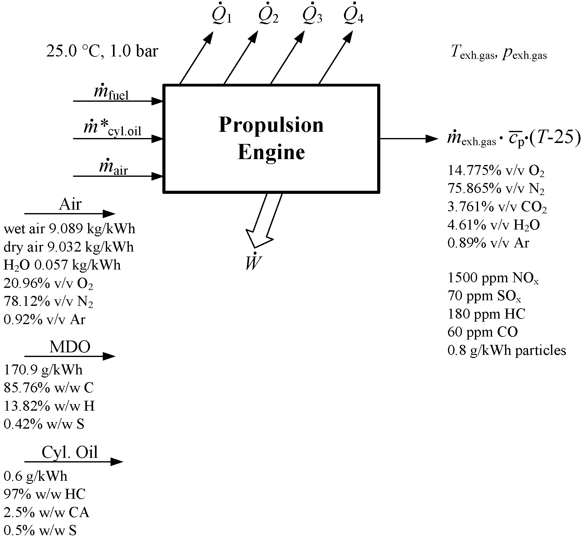
Although the exhaust gas composition was calculated precisely including the NO
x, particle and SO
2, the following mass molar composition was entered in the NIST program: 0.147748 O
2, 0.758649 N
2, 0.03768 CO
2, 0.046118 H
2O, 0.008934 Ar and 0.0008734 C
6H
14 what was calculated composition at 100%
SMCR (see
Figure 5). This exhaust gas composition is very close to MAN data [
43,
44] which also corresponds to 100%
SMCR. Molar mass composition is calculated at all off-design points. Exhaust gas composition at 80%
SMCR is 0.153097 O
2, 0.759912 N
2, 0.034293 CO
2, 0.042883 H
2O, 0.008949 Ar and 0.000866 C
6H
14. Gas constant
Rexh.gas = 0.2876835 kJ/kg at 100%
SMCR, 0.287693 at 80%
SMCR and 0.287699 kJ/kg at 50%
SMCR. Therefore, it is assumed that will not be great discrepancy if, in NIST program for next calculations only the value calculated for 100%
SMCR, is taken. The NO
x and SO
x were neglected as small quantities, while hexane C
6H
14 had nearly the same enthalpy as the unburned HC and soot.
The fuel consumption of the auxiliary diesel genset during navigation depends on ship demand. This research accounts for two possible network loads: full electric power and standard load. That means it is assumed that ship heat consumption is always the same at ISO standard conditions, while electrical power consumption could be full electrical power consumption (maximum power consumption) or standard power consumption.
Figure 5.
The calculated substance flow through the propulsion engine at 100% SMCR.
Figure 5.
The calculated substance flow through the propulsion engine at 100% SMCR.
The fuel savings compared to the auxiliary diesel engine (classical engine room with WHR for heat only) and to the WHR CHP steam turbine cycle are shown in
Figure 8,
Figure 9,
Figure 10,
Figure 11 and
Figure 12. Although the ORC technology has been developed and introduced in shore-based industrial plants for a few decades (geothermal energy, solar energy, biomass, waste heat,
etc.), the available literature and results useful for comparison are scarce.
3.1. Full Electrical Power Consumption during Navigation
Working fluid states before and after feeder/booster module are shown in
Table 5.
Table 5.
State points of working fluid R245fa; HFO feeder/booster heating.
Table 5.
State points of working fluid R245fa; HFO feeder/booster heating.
| State Point in the Diagram | 9 | 9' | 9'' | 9''' |
|---|
| Pressure, p (bar) | 45 | 42.75 | 42.75 | 2.2 |
| Temperature, T (°C) | 200 | 197 | 120 | 36.125 |
| Specific enthalpy, h (kJ/kg) | 561.72 | 560.04 | 370.20 | 370.20 |
| Specific entropy, s (kJ/kg K) | 1.9435 | 1.9420 | 1.5028 | 1.5595 |
| Density ρ (kg/m3) | 234.56 | 221.27 | 1039.95 | 12.469 |
| Additional vapour for module heating, (kg/s) | 1.0426 | 1.0426 | 1.0426 | 1.0426 |
Working fluid calculation results before and after the turbine are shown in
Table 6.
Table 6.
R245fa vapour state points before and after turbine; repeated calculation.
Table 6.
R245fa vapour state points before and after turbine; repeated calculation.
| State Point in the Diagram | 9 | 01 | 02s | 02 | 2s | 2 |
|---|
| Pressure, p (bar) | 45 | 42.75 | 2.32 | 2.32 | 2.2 | 2.2 |
| Temperature, T (°C) | 200 | 197 | 99.6 | 109.39 | 99.6 | 108.02 |
| Density, ρ (kg/m3) | 234.56 | 221.27 | 9.8543 | 10.109 | 9.8538 | 9.6064 |
| Saturation temperature, Tsat (°C) | – | – | 37.74 | 37.74 | 36.14 | 36.14 |
| Specific enthalpy vapour, h (kJ/kg) | 561.72 | 560.04 | 495.52 | 504.14 | 494.27 | 502.89 |
| Specific entropy, s (kJ/kg K) | 1.9435 | 1.9420 | 1.9420 | 1.9650 | 1.9420 | 1.9650 |
| Vapour quality, x (kg/kg) | – | – | Superh. * | Superh. | Superh. | Superh. |
| Vapour mass flow from turbine, (kg/s) | 20.52 | 20.52 | 20.52 | 20.52 | 20.52 | 20.52 |
| Add. vapour for module heating, (kg/s) | 1.0426 | – | – | – | – | – |
| Total condensate mass flow, (kg/s) | 21.5626 | – | – | – | – | – |
The data for the working fluid after the turbine and before heating are presented in
Table 7.
Table 7.
R245fa state points after the turbine and before heating; repeated calculation.
Table 7.
R245fa state points after the turbine and before heating; repeated calculation.
| State Point in the Diagram | 2 | 2' | 3 | 4 | 5 |
|---|
| Pressure, p bar | 2.2 | 2.2 | 2.2 | 2.2 | 45 |
| Temperature, T °C | 108.02 | 74.89 | 36.125 | 36.125 | 37.71 |
| Specific enthalpy vapour/liquid,
h kJ/kg | 502.89 | 469.29 | 430.90 | 247.32 | 250.58 |
| Specific entropy, s kJ/kg K | 1.9649 | 1.8727 | 1.7558 | 1.1622 | 1.1622 |
| Density ρ kg/m3 | 9.607 | 10.683 | 12.469 | 1,307.7 | 1,318.3 |
| R245fa mass flow, kg/s | 20.52 | 20.52 | 20.52 | 21.5626 | 21.5626 |
The data for the working fluid after the feed pump and after heating with jacket water, scavenged air and exhaust gases are presented in
Table 8.
Table 8.
R245fa state points at heating; repeated calculation.
Table 8.
R245fa state points at heating; repeated calculation.
| State Point in the Diagram | 6 | 7 | 9 |
|---|
| Pressure, p (bar) | 45 | 45 | 45 |
| Temperature, T (°C) | 75 | 150 | 200 |
| Specific enthalpy vapour/liquid,
h (kJ/kg) | 301.97 | 423.93 | 561.72 |
| Specific entropy, s (kJ/kg K) | 1.318 | 1.634 | 1.9435 |
| Density ρ (kg/m3) | 1210.6 | 857.69 | 12.469 |
| R245fa mass flow, (kg/s) | 21.563 | 21.5626 | 21.5626 |
Converged jacket water, scavenged air and exhaust gases data (state points) before and after cooling of working fluid, and after iterations are displayed in
Table 9.
Table 9.
Jacket water, scavenged air and exhaust gases state points after iteration.
Table 9.
Jacket water, scavenged air and exhaust gases state points after iteration.
| Parameter | Jacket Water | Scavenged Air | Exhaust Gases |
|---|
| State point | in | out | in | out | in | out |
| Pressure, p (bar) | 2.5 | 2.5 | 3.79 | 3.79 | 1.03 | 1.015 |
| Temperature, T (°C) | 83.535 | 58.898 | 193.0 | 138.11 | 238.5 | 150.0 |
| Specific enthalpy, h (kJ/kg) | 350.01 | 246.76 | 483.55 | 427.16 | 599.75 | 506.26 |
| Density ρ (kg/m3) | 969.62 | 983.82 | 2.8178 | 3.1949 | 0.6996 | 0.8337 |
| Mass flow rate (kg/s) | 10.8395 | 10.8395 | 47.111 | 47.111 | 48.0 | 48.0 |
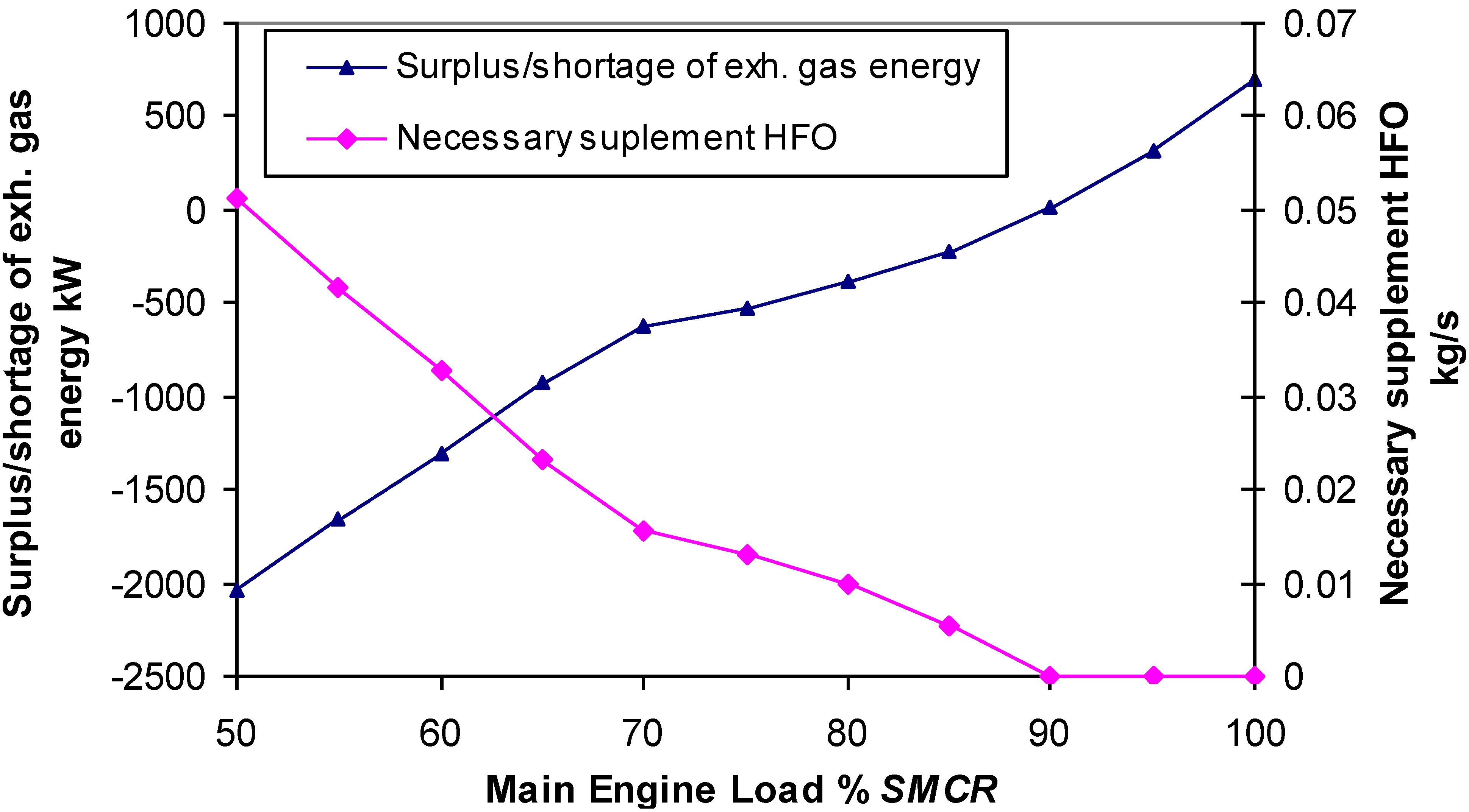
Surplus or shortage of exhaust gas energy, and necessary supplemental HFO at full electrical power are shown on
Figure 6.
Figure 6.
Surplus/shortage of exhaust gas energy and supplemental HFO at full electrical power.
Figure 6.
Surplus/shortage of exhaust gas energy and supplemental HFO at full electrical power.
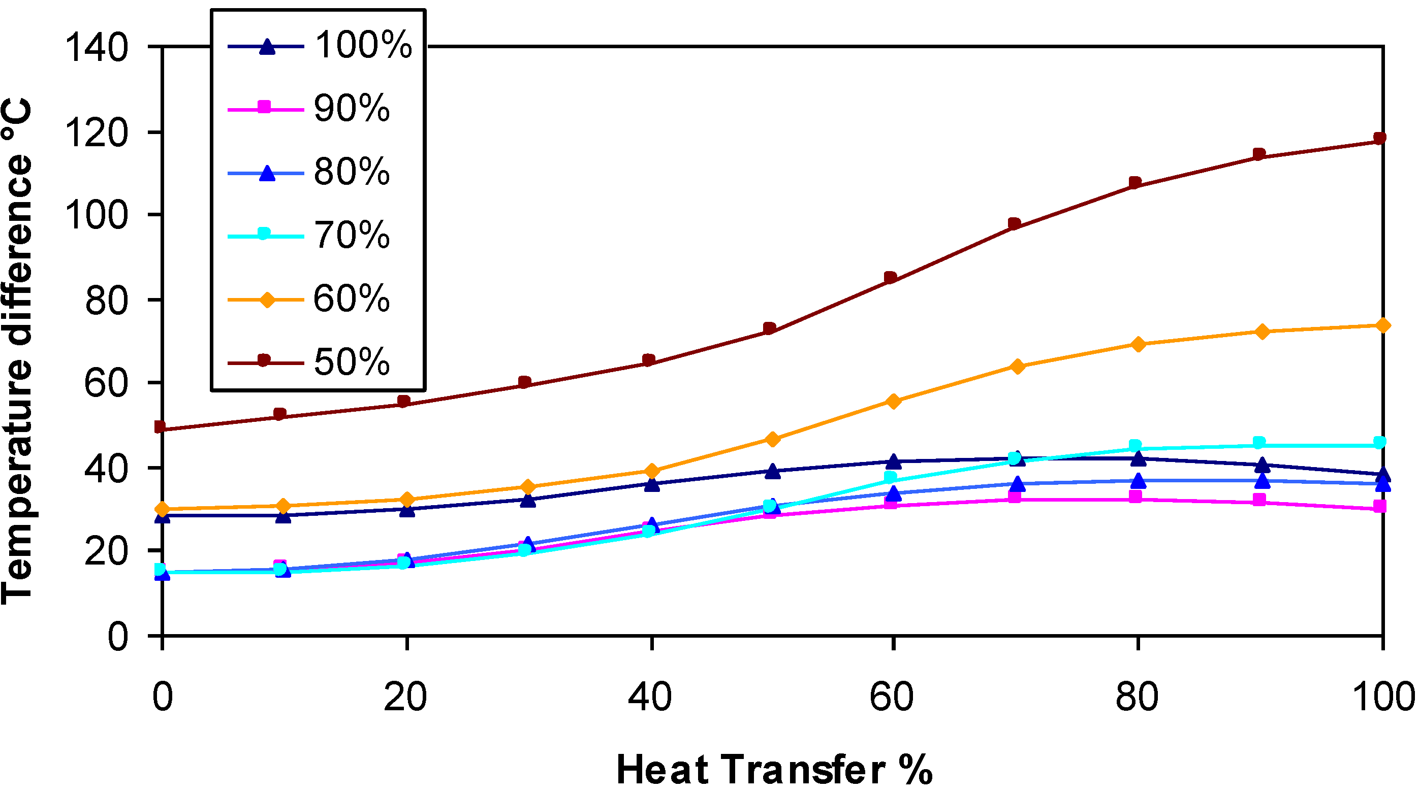
Parameters of exhaust gas and working fluid in exhaust gas boiler at 100%
SMCR and full electrical power are shown in
Table 10. The verification of temperature difference through exhaust gas boiler at main engine loads from 50% to 100% is shown in
Figure 7.
Table 10.
Heat transfer parameters in the boiler at 100% SMCR R245fa 912 kWe.
Table 10.
Heat transfer parameters in the boiler at 100% SMCR R245fa 912 kWe.
| Parameter | Value | Value | Value | Value | Value | Value | Value | Value | Value | Value | Value |
|---|
| Qi,ORC (%) | 0 | 10 | 20 | 30 | 40 | 50 | 60 | 70 | 80 | 90 | 100 |
| h1,ORC (kJ/kg) | 423.93 | 437.70 | 451.48 | 465.26 | 479.04 | 492.82 | 506.60 | 520.38 | 534.16 | 547.94 | 561.72 |
| T1,ORC (K) | 423.15 | 429.20 | 434.00 | 437.35 | 439.92 | 442.65 | 446.37 | 451.43 | 457.75 | 465.07 | 473.15 |
| T1,ORC (°C) | 150.0 | 156.05 | 160.85 | 164.20 | 166.77 | 169.50 | 173.22 | 178.28 | 184.60 | 191.92 | 200.0 |
| h1,gas (kJ/kg) | 536.58 | 542.90 | 549.22 | 555.53 | 561.85 | 568.16 | 574.48 | 580.80 | 587.11 | 593.43 | 599.74 |
| T1,gas (K) | 452.03 | 458.02 | 464.01 | 469.99 | 475.97 | 481.93 | 487.89 | 493.84 | 499.79 | 505.72 | 511.65 |
| T1,gas (°C) | 178.88 | 184.87 | 190.86 | 196.84 | 202.82 | 208.78 | 214.74 | 220.69 | 226.64 | 232.57 | 238.50 |
| ΔTgas/ORC(°C) | 28.88 | 28.82 | 30.01 | 32.64 | 36.05 | 39.28 | 41.52 | 42.41 | 42.03 | 40.65 | 38.50 |
Figure 7.
Temperature difference in the exhaust gas boiler with the organic working fluid at the main engine loads from 50% to 100% SMCR.
Figure 7.
Temperature difference in the exhaust gas boiler with the organic working fluid at the main engine loads from 50% to 100% SMCR.
The calculations showed significant HFO savings from 70% to 100%
SMCR at full electrical power consumption for CHP organic plant compared to classical auxiliary Diesel engine what is shown in
Figure 8. When compared to the auxiliary diesel genset, the fuel saved when using the R245fa CHP cycle for the 912 kWe ranged from 186 t
HFO/y for 50%
SMCR up to 1254 t
HFO/y. Higher main engine loads should generate higher fuel savings for the R245fa CHP plant.
Figure 8.
R245fa CHP Plant 912/1015 kWe savings vs. Diesel genset.
Figure 8.
R245fa CHP Plant 912/1015 kWe savings vs. Diesel genset.
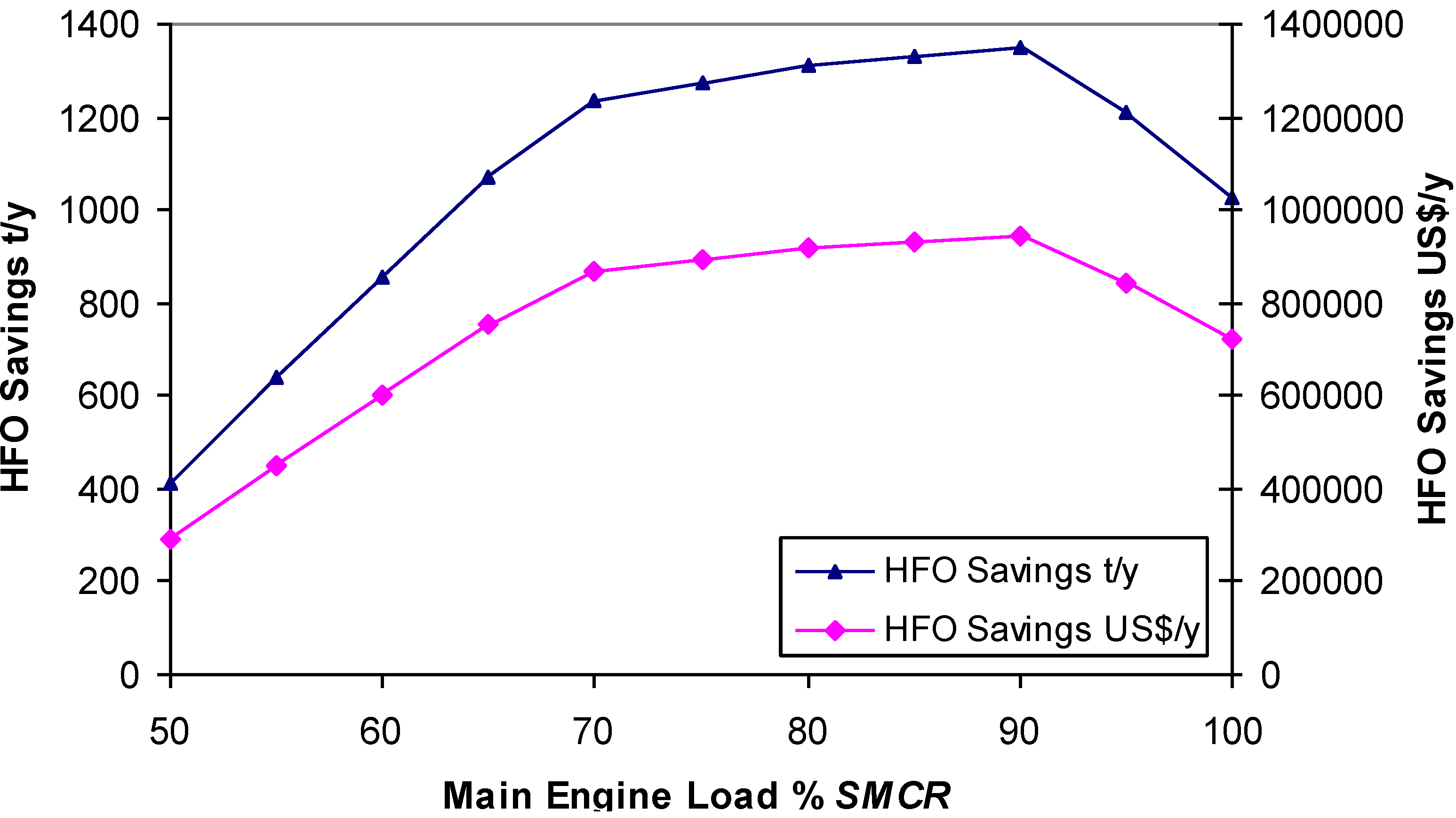
The ORC fuel savings compared to the steam turbine cycle range from 413 t
HFO/y up to 1346 t
HFO/y. The highest ORC savings compared to the steam turbine cycle are obtained during main engine loads ranging from 75% to 90%, which is normal operating power of the main engine (see
Figure 9).
Even though the waste heat from the main engine is the same for the steam and R245fa vapour cycle, the fuel consumption during the steam CHP cycle is the highest, except for the main engine load between 95% and 100%
SMCR.
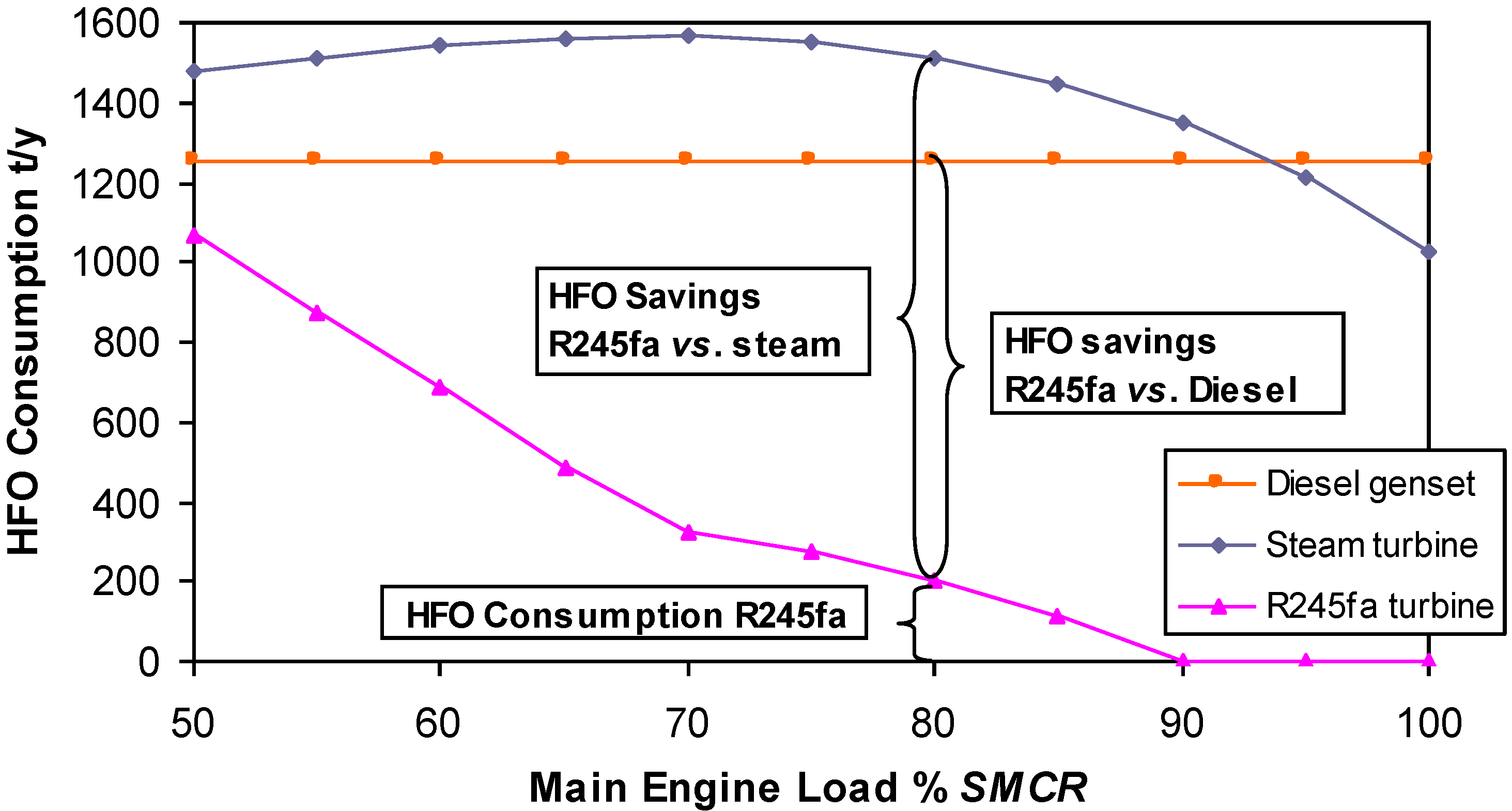
Figure 10 shows HFO savings of R245fa CHP plant
vs. Diesel genset and
vs. steam CHP plant. Because the
NCR in the observed tanker plant is 80%
SMCR, no significant fuel savings are obtainable when utilising the steam CHP plant.
Figure 9.
R245fa CHP Plant HFO savings versus the steam CHP Plant 912/1015 kWe
Figure 9.
R245fa CHP Plant HFO savings versus the steam CHP Plant 912/1015 kWe
Figure 10.
HFO Consumption when producing full electrical power 912/1015 kWe and heat by Diesel, steam CHP Plant and organic CHP Plant.
Figure 10.
HFO Consumption when producing full electrical power 912/1015 kWe and heat by Diesel, steam CHP Plant and organic CHP Plant.
The computational results show that the fuel savings in the R245fa CHP plant are considerable when compared to those of the steam cycle and the auxiliary diesel genset.
Figure 8,
Figure 9 and
Figure 10 clearly show that the R245fa CHP plant is superior to the auxiliary diesel engine and, to a greater extent, the steam CHP cycle. This distinctive advantage applies to the entire operational range of the main engine.
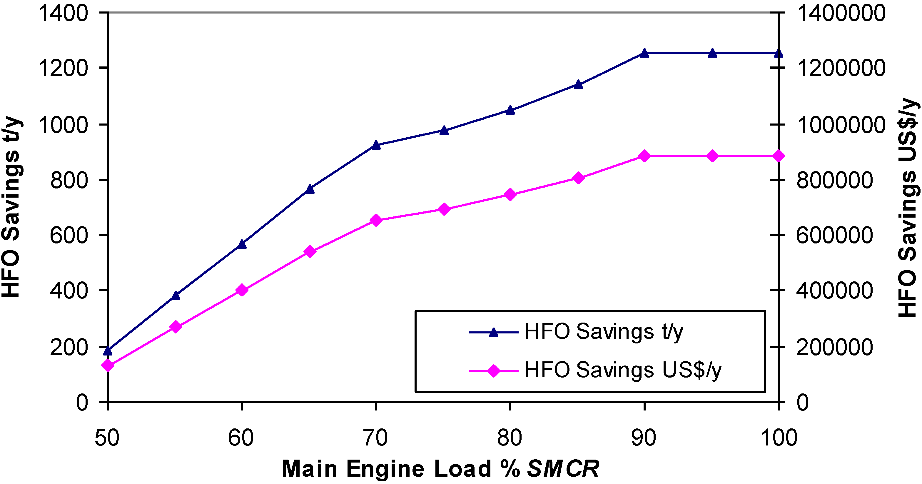
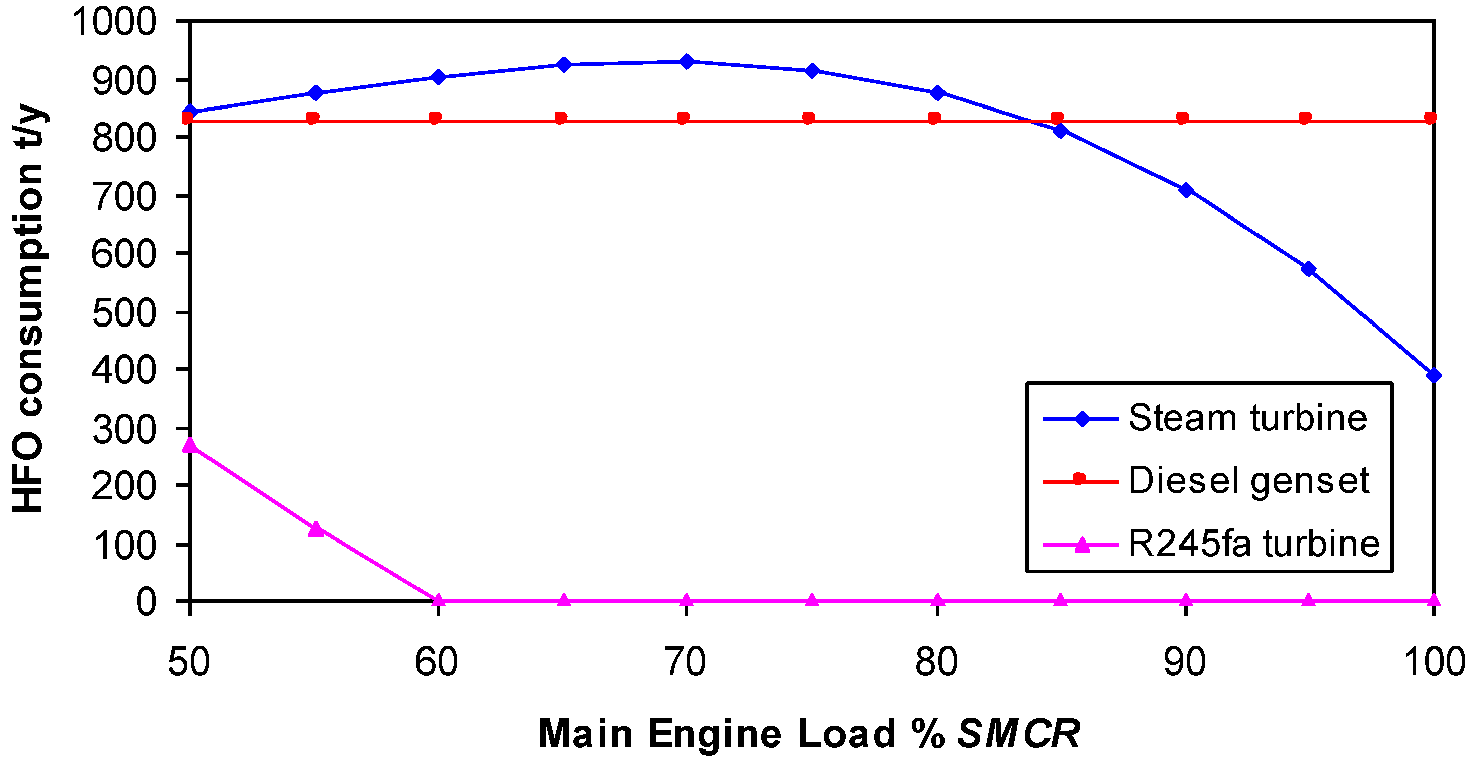
3.2. Standard Electrical Power Consumption during Navigation
The computational results show that for 620 kWe, the R245fa CHP fuel savings are significant compared to the remaining two analysed systems.
Figure 11 and
Figure 12 clearly show that the R245fa CHP is superior to both the auxiliary diesel genset and the steam CHP cycle. This distinctive advantage applies to the entire operational range of the main engine.
Figure 11.
HFO Consumption when producing standard electrical power 620/692 kWe and heat.
Figure 11.
HFO Consumption when producing standard electrical power 620/692 kWe and heat.
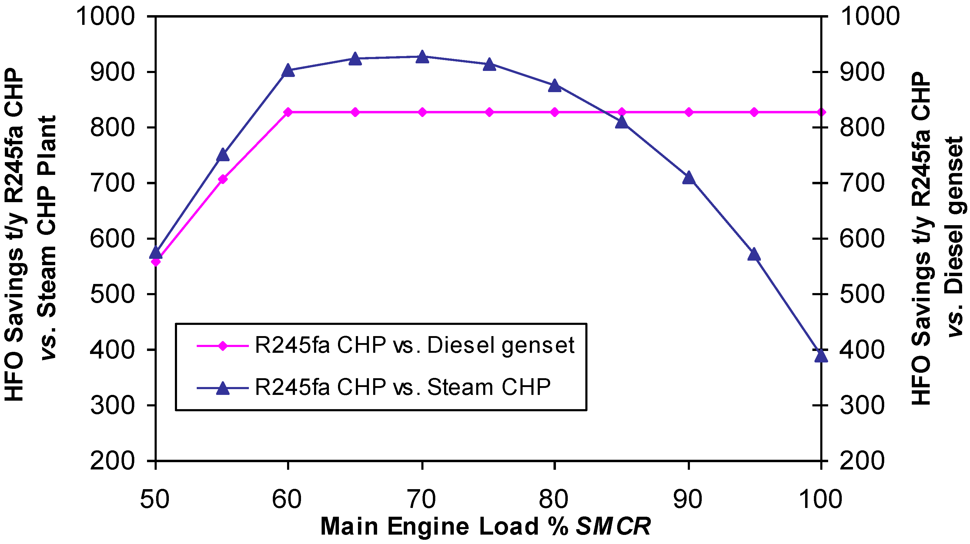
Figure 12.
R245fa CHP HFO savings vs. diesel genset and Steam CHP Plant 620/692 kWe.
Figure 12.
R245fa CHP HFO savings vs. diesel genset and Steam CHP Plant 620/692 kWe.
The fuel savings during the ORC cycle compared to the auxiliary diesel engine range from 560 tHFO/y to 828 tHFO/y. The fuel savings in the ORC compared to the steam turbine cycle range from 400 tHFO/y up to 927 tHFO/y. The highest savings obtained by the OR cycle are in the main engine loads range from 55% to 85% SMCR compared to the steam turbine cycle.
Partial model validation can be performed by comparing the results obtained by [
26] and the results obtained in the real-life WHR systems built by Dresser Rand, Mitsubishi Heavy Industries Ltd, Shinko Ind. Ltd and Siemens. MAN B&W [
45] for a propulsion engine power below 15,000 kW an ORC plant recommends, while for 15,000 kW to 25,000 kW the power gas turbine or superheated steam turbine cycle recommends.
When using organic fluids in power plants the following problems occur:
In vapour turbine plants, it is almost impossible to avoid at least minor leakage of the working fluid into the atmosphere, guaranteeing a certain level of pollution and a loss of an expensive fluid that must be accounted for.
Unfortunately, not enough documented insights are available regarding the maximum working temperature that the R245fa fluid can withstand without degradation. The Honeywell Company confirmed that the R245fa decomposition temperature is above 250 °C [
32]. Steam turbine allows an oil-free operation thus avoiding the potential interaction between lubricant and working fluid. In addition, a small amount of decomposition could be tolerated in power cycles as long as the pyrolysis products are not corrosive and the cycle thermodynamics maintains its functionality.
Because the process with R245fa has a much larger mass flow rate, the required feed pump power is considerably higher than the steam cycle. Therefore, the electric power necessary for the R245fa cycle is 1015 kWe instead of 912 kWe and, 692 kWe instead of 620 kWe.
Our proposed CHP plant using ORC with R245fa fluid showed great improvements in all engine loads above 50%
SMCR. The results of this research reveal the advantage of supercritical ORC during low temperature waste heat recovery processes, compared to the ordinary steam turbine process. The supercritical ORC ensures the use of low temperature exhaust gas waste heat, maintaining the pinch point at 15 °C; this scenario does not occur during a steam cycle. These results agree with those of Teng
et al. [
46].
4. Conclusions
This paper analyses the savings in fuel consumption for the WHR CHP plant compared to the classical ship power plant whose heat demands are covered by a steam boiler and whose electrical power demands are covered by the auxiliary diesel genset, when the ship is under way. We compared our proposed system with: (i) a conventional engine room with partial WHR system and (ii) an advanced engine room with WHR proposed by MAN and Wärtsilä. The comparison has not been performed according to the efficiency of these cycles, focussing instead on savings in fuel consumption. The authors assume that this research can contribute to rational energy use and environment protection in the following ways:
An analytical model has been developed; this computational algorithm involves all components of the complex cogeneration process that are suitable for applications with various working fluids while including mechanical work and heat production. Therefore, the aspects of the first and the second law of thermodynamics have been implicitly accounted for.
Some advanced low speed diesel engines use WHR systems; however they are based on injection of higher portion of fuel and shorter expansion which results in more recoverable energy in the exhaust gases but at expense of reduced main engine efficiency. Our research was based on a standard engine operating at maximum efficiency while burning a small quantity of additional fuel in the exhaust gas-fired boiler only if needed.
This research has explored the application of supercritical ORC during the production of electrical energy and heat, using waste heat energy from the main engine jacket water, scavenged air and exhaust gases. An analysis of the obtained results shows that the ST plant does not yield significant fuel savings. However, a CHP plant with R245fa fluid using supercritical ORC meets all of the demands for electrical energy and heat while burning only a small amount of additional fuel in auxiliary boiler.
To enhance the cogeneration efficiency, the maximum temperature of the applied organic fluid should be increased to increase the turbine outlet temperature and improving the quality of the heat consumed on board.
This analysis has revealed the possible savings in fuel consumption when using supercritical ORC CHP for low temperature WHR in ship propulsion plants. Concurrently, the lower fuel consumption reduces green-house gases emissions and their environmental impact.

