1. Introduction
In order to improve the heat exchange efficiency and extend surface heat transfer, H-type finned tubes have been widely used in boilers and waste heat recovery in recent years. H-type finned tubes are derived largely from rectangle finned tubes. Because of their unique groove structure on the fin surface, H-type finned tubes have excellent anti-wear and anti-fouling performance [
1].
Numerous experimental and numerical studies have been conducted on the heat transfer and resistance characteristics of finned tubes. These studies mainly focus on spiral finned tubes [
2,
3], plain finned tubes [
4,
5,
6,
7] and serrated finned tubes [
8,
9], while fewer studies exist, however, on the heat transfer and resistance characteristics of H-type finned tubes.
Tong [
10], Zhang
et al. [
11] and Yu
et al. [
1] studied the heat transfer and pressure drop characteristics of H-type finned tube banks by numerical simulation. The effects of geometric parameters and Reynolds number were examined. Yu
et al. [
12], Chen and Lai [
13] and Wu
et al. [
14] performed experimental tests to examine the heat transfer and resistance characteristics of H-type finned tube banks and provided some reference for the design of the H-type finned tube bundles. Much research is limited to single factor experiments, limiting the obtained experimental correlations due to restricted experimental conditions and different fin structures. Limitations create an inability to fully explain how factors synthetically affect the heat transfer and pressure drop. Varying test conditions cause the results of H-type finned tube’s heat exchange coefficient and resistance coefficient to be quite different, necessitating comprehensive experimental research on the heat transfer and resistance characteristics of H-type finned tubes.
In this paper, an open high-temperature wind tunnel is applied to study the heat transfer and pressure drop characteristics of H-type finned tubes with different fin pitch, fin height and fin width. The relationships between fin efficiency, convective heat transfer coefficient, integrated heat transfer capacity and resistance coefficient and air velocity, fin pitch, fin height and fin width are studied. The predictive correlations of fin efficiency, Nusselt number and Euler number are then developed. A theoretical basis for heat transfer and resistance characteristics of H-type finned tubes and an important reference for their engineering application could result from the research.
2. Experimental Section
2.1. Experimental Setup
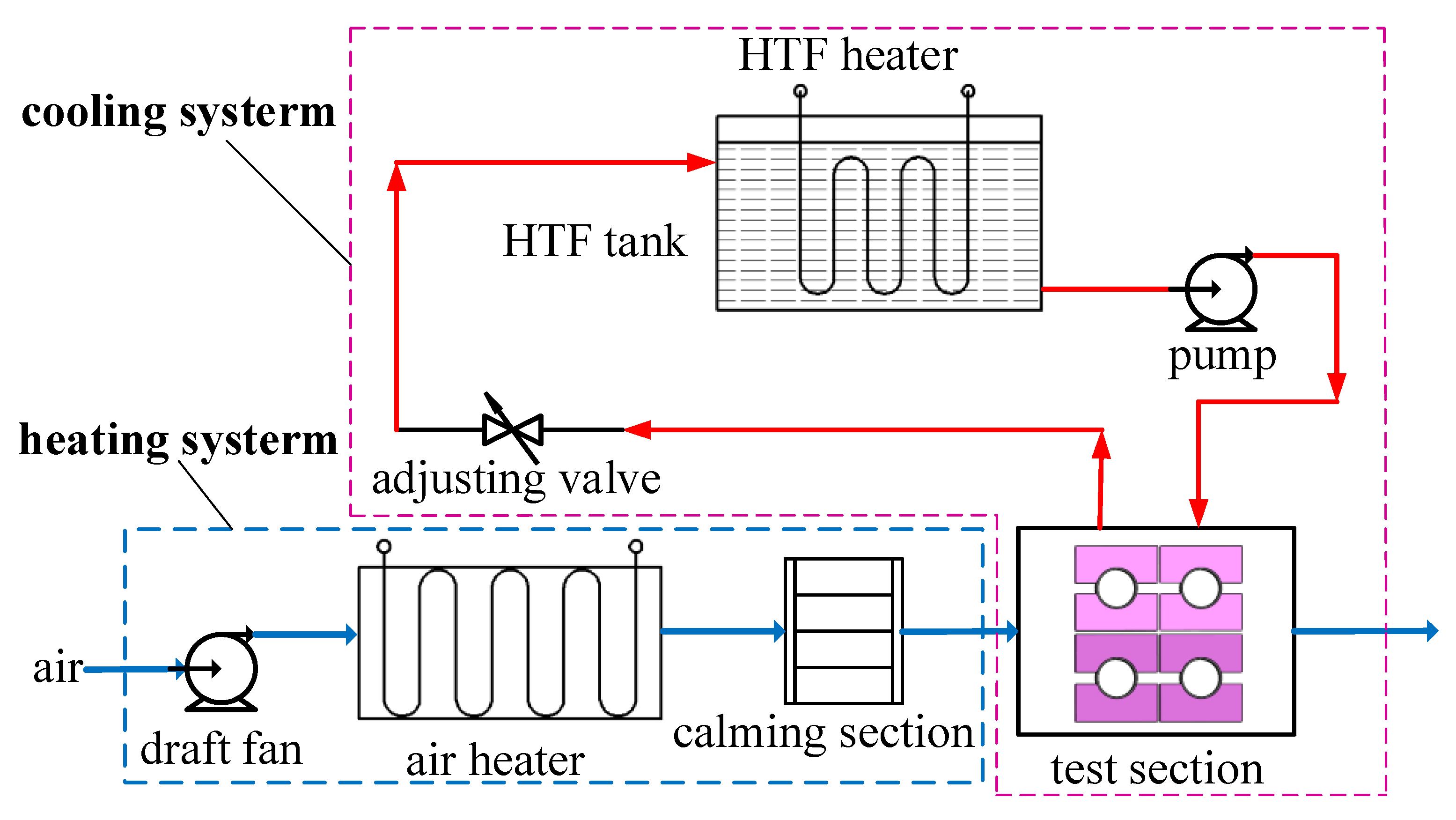
Experiments were carried out in an open high-temperature wind tunnel equipped with heating and cooling systems, as shown in
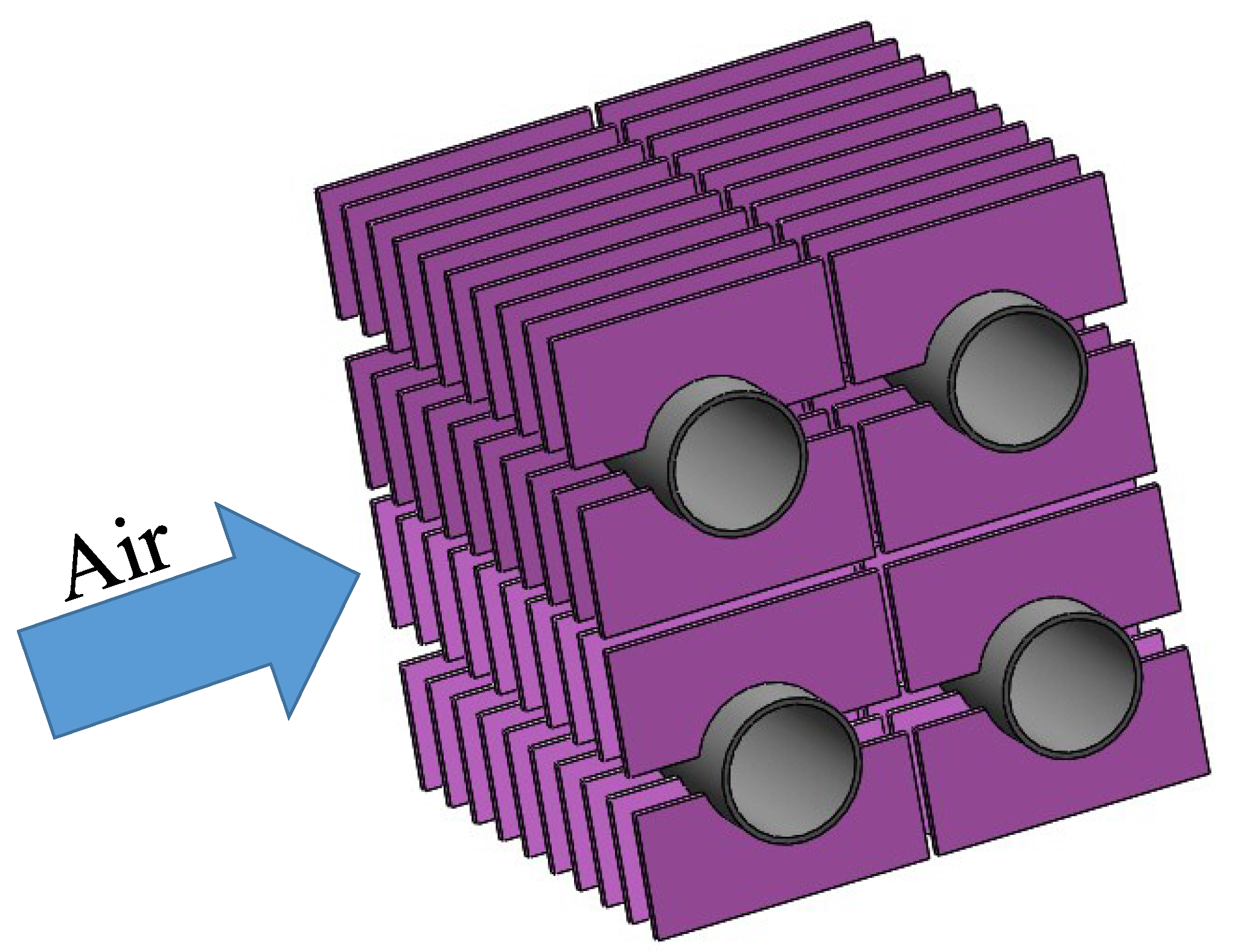
Figure 1. The heating system includes a draft fan, an air heater and the calming section. The cooling system consists of a circulating and temperature-controlled Heat Transfer Fluid (HTF) tank, a pump, the test section and an adjusting valve. The test section is a 2 × 2 in-line H-type finned tube bank, as shown in
Figure 2.
Figure 1.
Schematic diagram of the experimental system.
Figure 1.
Schematic diagram of the experimental system.
Figure 2.
Schematic diagram of the test section.
Figure 2.
Schematic diagram of the test section.
2.2. Data Processing
The heat transfer and resistance characteristics of H-type finned tube banks were studied by varying air velocity, fin pitch, fin height and fin width.
The physical meaning of fin efficiency is the ratio of the actual heat transfer and the given heat transfer assuming that the fin surface temperature is equal to that of the base tube, which can be expressed as:
According to Equation (1), fin efficiency ηf can be derived by measuring the fin temperatures of different H-type finned tubes.
To represent the correlativity between the heat transfer or pressure drop and the fin-side flow conditions, the dimensionless norms, such as the Nusselt number, Euler number and Reynolds number, were used in this paper. In the calculations of the above norms, the arithmetic mean temperature was used for the calculations of gas physical properties. The outer diameter of the tube was adopted as the characteristic length for the Reynolds and Nusselt numbers, and the air mass flux in the narrowest cross flow area was adopted to calculate the characteristic velocity for the Reynolds and Euler numbers [
9].
When air flows across the H-type finned tube bank, its heat transfer and pressure drop are effected by a lot of factors such as gas velocity, bank arrangement, tube pitches, tube structure, tube number and air characteristic. To facilitate experimental data processing, convective heat transfer coefficient is expressed as:
The resistance characteristic of H-type finned tube banks can be described by dimensionless criterion Euler Number:
2.3. Testing Tube Banks
Air velocity
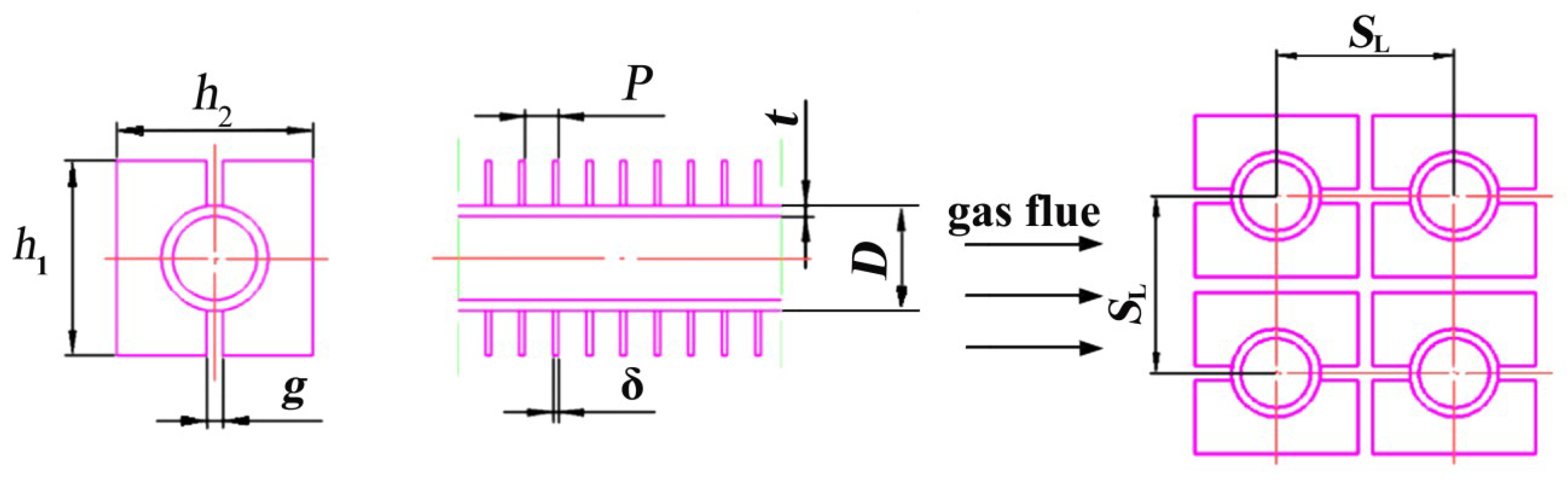
v of the test section was set as 6, 8, 10, 12 and 15 m/s. The structure of the H-type finned tube and tube bank is shown in
Figure 3. Six H-type finned tubes banks with different geometric parameters were tested, as shown in
Table 1.
Figure 3.
Geometric schematic of H-type finned tube and tube bank.
Figure 3.
Geometric schematic of H-type finned tube and tube bank.
Table 1.
Main geometry data for testing H-type finned tube banks.
Table 1.
Main geometry data for testing H-type finned tube banks.
| Parameter | Nomen-clature | Bank A | Bank B | Bank C | Bank D | Bank E | Bank |
|---|
| Tube diameter (mm) | D | 38 | 38 | 38 | 38 | 38 | 38 |
| Tube thickness (mm) | t | 4 | 4 | 4 | 4 | 4 | 4 |
| Fin height (mm) | h1 | 89 | 89 | 89 | 90 | 90 | 90 |
| Fin width (mm) | h2 | 95 | 95 | 95 | 105 | 105 | 105 |
| Slit width (mm) | g | 13 | 13 | 13 | 13 | 13 | 13 |
| Fin thickness (mm) | δ | 2.5 | 2.5 | 2.5 | 2.5 | 2.5 | 2.5 |
| Fin pitch (mm) | P | 12.7 | 19.05 | 25.4 | 12.7 | 19.05 | 25.4 |
| Finned ratio | β | 9.74 | 7.12 | 5.37 | 10.99 | 7.99 | 5.99 |
| Total heat exchanging surface per meter H-type finned tube (m2) | At | 1.22 | 0.83 | 0.67 | 1.39 | 0.96 | 0.75 |
| Transversal tube spacing (mm) | ST | 98 | 98 | 98 | 108 | 108 | 108 |
| Longitudinal tube spacing (mm) | SL | 92 | 92 | 92 | 93 | 93 | 93 |
3. Results and Discussion
3.1. Fin Efficiency
Temperatures of the H-type fins were measured in this experiment. Then the relationship between fin efficiency and air velocity and the experimental correlation of fin efficiency was derived. The relationship between fin efficiency
ηf and air velocity
v is shown in
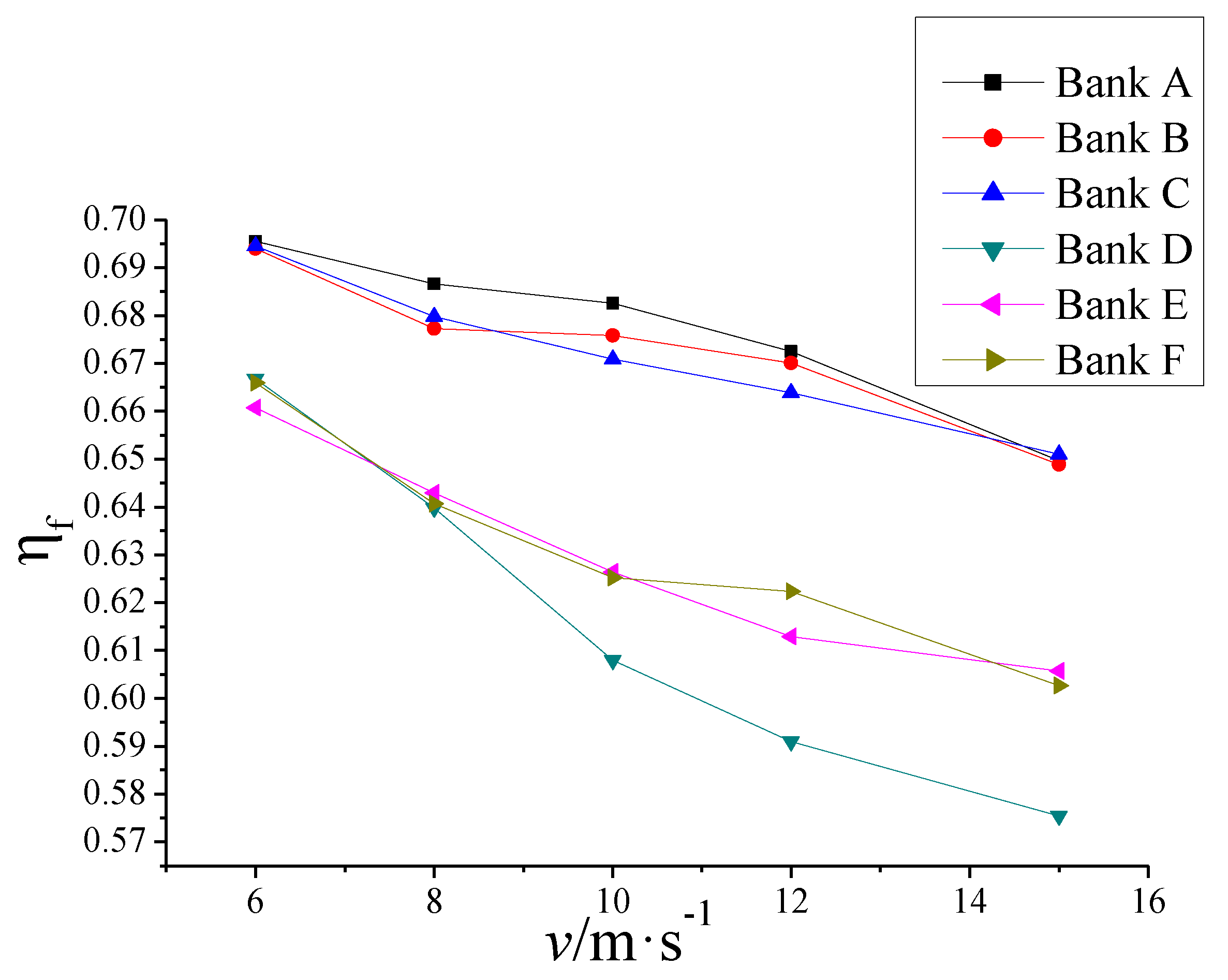
Figure 4. As air velocity, fin height and fin width increase, fin efficiency decreases. Fin pitch has little effect on fin efficiency. So fin efficiency is primarily associated with air velocity, fin height and fin width. With the increase of fin height and fin width, the average temperatures of the fins increases [
11]. According to the definition of fin efficiency, it will decrease with the average temperatures of the fins.
Figure 4.
Relationship between fin efficiency ηf and air velocity v.
Figure 4.
Relationship between fin efficiency ηf and air velocity v.
Fin efficiency is related to convective heat transfer coefficient α, fin height
h1, fin width
h2 and fin thermal conductivity λ:
According to the experiments, fin efficiency is proportional to the air velocity but inversely proportional to fin height and fin width, so it can be expressed as:
Since
h1,
h2 and
v are independent factors, Equation (5) can be expressed as:
The experimental data of fin efficiency is shown is
Table 2. The data is composed of a number of independent factors. When processing these independent factors, the method of variable separation was used to analyse their effects on fin efficiency. And the fitting correlation was obtained by nonlinear fitting method. The obtained coefficients
P1,
P2,
P3 and
P4 are 7.41, −0.116, −2.32 and −0.198. Then Equation (6) can be expressed as:
The correlation is suitable for: v = 6–15 m/s. Its relative error is 2.09%.
Table 2.
Experimental fin efficiency data.
Table 2.
Experimental fin efficiency data.
| Air velocity (m/s) | Bank A | Bank B | Bank C | Bank D | Bank E | Bank F |
|---|
| 6 | 0.6955 | 0.6939 | 0.6946 | 0.6668 | 0.6608 | 0.6659 |
| 8 | 0.6866 | 0.6773 | 0.6798 | 0.6398 | 0.6429 | 0.6407 |
| 10 | 0.6826 | 0.6758 | 0.6709 | 0.6081 | 0.6264 | 0.6252 |
| 12 | 0.6775 | 0.6701 | 0.6639 | 0.5913 | 0.6129 | 0.6223 |
| 15 | 0.6497 | 0.6489 | 0.6511 | 0.5754 | 0.6057 | 0.6027 |
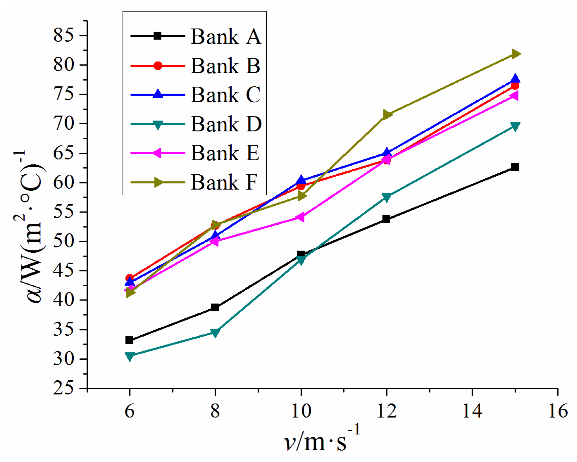
3.2. Convective Heat Transfer Coefficient
The relationship between convective heat transfer coefficient α and air velocity
v is shown in
Figure 5. With the same fin pitch, convective heat transfer coefficient α decreases with the increase of fin height and fin width. Conversely, with the same fin height and fin width, as fin pitch increases, convective heat transfer coefficient increases and the effect of fin pitch on convective heat transfer coefficient α becomes less. Therefore convective heat transfer coefficient is proportional to fin pitch but inversely proportional to fin height and fin width. With the increase of fin pitch and decrease of fin height and fin width, finned ratio increases, which leads to the decrease of heat transfer efficiency of finned tubes [
15], so convective the heat transfer coefficient will decrease.
Figure 5.
Relationship between convective heat transfer coefficient α and air velocity v.
Figure 5.
Relationship between convective heat transfer coefficient α and air velocity v.
The terms υ,
h1,
h2,
P, ρ, λ,
cp and
v are independent factors. To facilitate data processing, Equation (2) was analysed in dimensionless form:
The experimental data of convective heat transfer coefficient α is shown in
Table 3, which is composed of some independent factors. When processing the independent factors, the method of variable separation was used to analyse their effects on convective heat transfer coefficient. Nonlinear fitting method was taken to process the experimental data to obtain the fitting correlation. The corresponding coefficients
P1,
P2,
P3,
P4 and
P5 are 0.053, 0.756, −0.212, −0.294 and 0.155. Then Equation (10) can be expressed as:
The correlation is suitable for: Re = 5000–18000. The relative error of this correlation is 2.79%.
Table 3.
Experimental convective heat transfer coefficient data α (W·(m2·°C)−1).
Table 3.
Experimental convective heat transfer coefficient data α (W·(m2·°C)−1).
| Air velocity (m/s) | Bank A | Bank B | Bank C | Bank D | Bank E | Bank F |
|---|
| 6 | 33.18 | 43.69 | 43.01 | 30.57 | 41.75 | 41.31 |
| 8 | 38.67 | 52.68 | 50.90 | 34.56 | 49.99 | 52.82 |
| 10 | 47.73 | 59.43 | 60.32 | 46.94 | 54.16 | 57.77 |
| 12 | 53.74 | 63.82 | 65.01 | 57.63 | 63.96 | 71.52 |
| 15 | 62.60 | 76.48 | 77.53 | 69.70 | 74.81 | 81.88 |
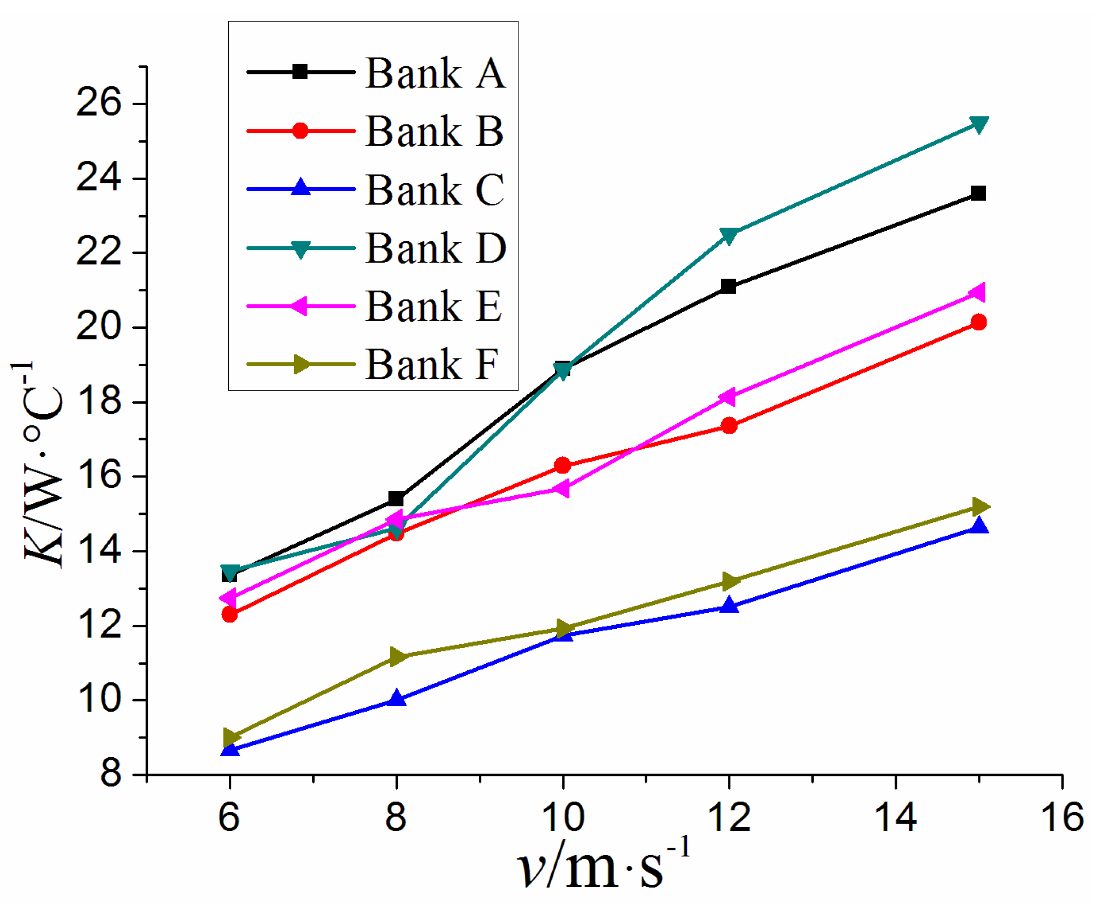
3.3. Integrated Heat Transfer Capacity
Integrated heat transfer capacity is a criterion to measure the heat transfer performance of finned tubes, and it is defined as the product of convective heat transfer coefficient α and surface area of H-type finned tube. The relationship between integrated heat transfer capacity and air velocity
v is shown in
Figure 6. Integrated heat transfer capacity is related to fin efficiency, convective heat transfer coefficient and finned ratio. Though the fin efficiency and convective heat transfer coefficient of Bank D are the smallest, its finned ratio is the largest, so the integrated heat transfer capacity
K of Bank D is the best.
Figure 6.
The relationship between integrated heat transfer capacity K and air velocity v.
Figure 6.
The relationship between integrated heat transfer capacity K and air velocity v.
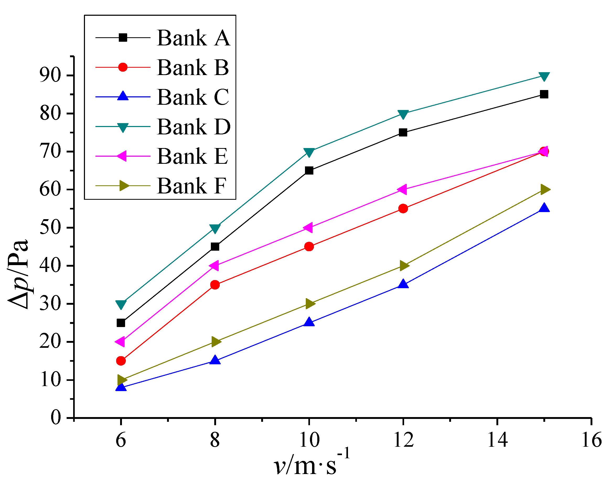
3.4. Pressure Drop
The relationship between pressure drop and air velocity
v is shown in
Figure 7. With the same fin pitch, pressure drop increases with the increase of fin height and fin width, as the bigger fin experiences more friction.
Figure 7.
Relationship between pressure drop and air velocity.
Figure 7.
Relationship between pressure drop and air velocity.
Since there is less contact area between air and fins with bigger fin pitch, pressure drop decreases with the increase of fin pitch. According to Equation (3), Euler number is related to air velocity and tube structure:
By the dimensionless and separated variable method, Equation (10) can be turned into Equation (11):
Fin height, fin width and air velocity are independent factors. To facilitate data processing, the dimensionless method was utilized. The experimental data of pressure drop is shown in
Table 4. The nonlinear fitting method was used to process the experimental data to obtain a fitting correlation. The corresponding coefficients
P1,
P2 and
P3 are 19.14, −0.57 and 1.3. Then Equation (11) can be expressed as:
The correlation is suitable for: Re = 5,000–18,000. Its relative error is 3.7%.
Table 4.
Experimental pressure drop data Δp (Pa).
Table 4.
Experimental pressure drop data Δp (Pa).
| Air velocity (m/s) | Bank A | Bank B | Bank C | Bank D | Bank E | Bank F |
|---|
| 6 | 25 | 15 | 8 | 30 | 20 | 10 |
| 8 | 45 | 35 | 15 | 50 | 40 | 20 |
| 10 | 65 | 45 | 25 | 70 | 50 | 30 |
| 12 | 75 | 55 | 35 | 80 | 60 | 40 |
| 15 | 85 | 70 | 55 | 90 | 70 | 60 |
4. Conclusions
A set of experiments was performed to evaluate the influence of fin height, fin width, fin pitch and finned ratio on the heat transfer, pressure drop and overall thermal performance of H-type finned tube banks. Based on the experimental results, the following conclusions were drawn:
As air velocity
v, fin height
h1 and fin width
h2 increase, fin efficiency η
f decreases. Its experimentally derived correlation is:
The correlation is suitable for: υ = 6–15 m/s. The relative error of this correlation is 2.09%.
Convective heat transfer coefficient α is proportional to fin pitch
P, but inversely proportional to fin height
h1 and fin width
h2. The correlation of
Nu is:
The correlation is suitable for: Re = 5,000–18,000. Its relative error is 2.79%.
Integrated heat transfer capacity is related to fin efficiency, convective heat transfer coefficient and finned ratio. Though the fin efficiency and convective heat transfer coefficient of Bank D are the smallest, its finned ratio is the biggest, so the integrated heat transfer capacity of Bank D is the best.
Pressure drop Δ
p increases with the increase of fin height
h1 and fin width
h2. The correlation of
Eu is:
The correlation is suitable for: Re = 5,000–18,000. The relative error of this correlation is 3.7%.
Nomenclature:
| ηf | fin efficiency |
| α | convective heat transfer coefficient (W/(m2·°C)) |
| Ff | fin area (m2) |
| tw | temperature of tube wall close to high temperature fluid (°C) |
| tf | fin temperature (°C) |
| υ | kinematic viscosity (m2/s) |
| h1 | fin height (mm) |
| h2 | fin width (mm) |
| P | fin pitch (mm) |
| ρ | air density (kg/m3) |
| λ | fin thermal conductivity (W/(m·°C)) |
| cp | air specific heat (J/(kg·°C)) |
| v | average air velocity of the test section (m/s) |
| Δp | he pressure drop of the tube bank (Pa) |
| Nu | Nusselt number = αl/λa |
| λa | air thermal conductivity (W/(m·°C)) |
| Re | Reynolds number = υl/v |
| Eu | Euler number |
| L | qualitative dimension (mm) |
| P1, P2, P3, P4, P5 | coefficients in equations |
Acknowledgments
This research was supported by the National Key Technology R&D Program of China (No. 2011BAK06B04) and the Fundamental Research Funds for the Central Universities.
Author Contributions
Qinxin Zhao and Heng Chen conceived and designed the experiments. Heng Chen, Yungang Wang, Haidong Ma, Yuxin Li and Zhongya Chen performed the experiments. All authors analyzed the data. All authors discussed the results and co-wrote and commented on the manuscript.
Conflicts of Interest
The authors declare no conflict of interest.
References
- Jin, Y.; Tang, G.H.; He, Y.L.; Tao, W.Q. Parametric study and field synergy principle analysis of H-type finned tube bank with 10 rows. Int. J. Heat Mass. Tran. 2013, 60, 241–251. [Google Scholar] [CrossRef]
- Zhang, J.W.; Zhang, Z. A numerical study on fully developed fluid flow and heat transfer in a spiral finned tube. Chin. J. Chem. Eng. 1999, 7, 56–66. (In Chinese) [Google Scholar]
- Li, L.J.; Cui, W.Z.; Liao, Q.; Xin, M.D.; Jen, T.C.; Chen, Q.H. Heat transfer augmentation in 3D internally finned and microfinned helical tube. Int. J. Heat Mass Tran. 2005, 48, 1916–1925. [Google Scholar]
- Wang, C.C.; Chi, K.Y. Heat transfer and friction characteristics of plain fin-and-tube heat exchangers, part I: New experimental data. Int. J. Heat Mass Tran. 2000, 43, 2681–2691. [Google Scholar] [CrossRef]
- Hasan, A.; Siren, K. Performance investigation of plain and finned tube evaporatively cooled heat exchangers. Appl. Therm. Eng. 2003, 23, 325–340. [Google Scholar] [CrossRef]
- Kim, Y.; Kim, Y. Heat transfer characteristics of flat plate finned-tube heat exchangers with large fin pitch. Int. J. Refrig. 2005, 28, 851–858. [Google Scholar] [CrossRef]
- Choi, J.M.; Kim, Y.; Lee, M.; Kim, Y. Air side heat transfer coefficients of discrete plate finned-tube heat exchangers with large fin pitch. Appl. Therm. Eng. 2010, 30, 174–180. [Google Scholar] [CrossRef]
- Lemouedda, A.; Schmid, A.; Franz, E.; Breuer, M.; Delgado, A. Numerical investigations for the optimization of serrated finned-tube heat exchangers. Appl. Therm. Eng. 2011, 31, 1393–1401. [Google Scholar] [CrossRef]
- Ma, Y.; Yuan, Y.; Liu, Y.; Hu, X.; Huang, Y. Experimental investigation of heat transfer and pressure drop in serrated finned tube banks with staggered layouts. Appl. Therm. Eng. 2012, 37, 314–323. [Google Scholar] [CrossRef]
- Tong, L. 3D numerical analysis of heat transfer characteristics for H-type finned tube. Mech. Electr. Eng. Mag. 2007, 152, 79–81. [Google Scholar]
- Zhang, Z.; Wang, Y.; Zhao, Q. Numerical study on performance optimization of H-type finned tubes. J. Power Eng. 2010, 30, 941–946. [Google Scholar]
- Yu, X.; Yuan, Y.; Ma, Y.; Liu, H. Experimental tests and numerical simulation on heat transfer and resistance characteristics of H-type finned tube banks. J. Power Eng. 2010, 30, 433–438. [Google Scholar]
- Chen, H.-T.; Lai, J.-R. Study of heat-transfer characteristics on the fin of two-row plate finned-tube heat exchangers. Int. J. Heat Mass Tran. 2012, 55, 4088–4095. [Google Scholar] [CrossRef]
- Wu, X.; Shang, Y.; Wang, J.; Ren, G. Experimental research heat transfer characteristics of H-type finned tube bundles. J. Southeast Univ. Nat. Sci. Ed. 2013, 43, 88–93. (In Chinese) [Google Scholar]
- Yang, S.; Tao, W. Heat Transfer, 4th ed.; Higher Education Press: Beijing, China, 2006; pp. 57–70. (In Chinese) [Google Scholar]
© 2014 by the authors; licensee MDPI, Basel, Switzerland. This article is an open access article distributed under the terms and conditions of the Creative Commons Attribution license (http://creativecommons.org/licenses/by/4.0/).


