1. Introduction
Desiccant cooling systems (DCS) are an interesting alternative to conventional cooling-based air conditioning systems with electrically-driven vapor compression cooling units, as they allow a more accurate humidity control, a better indoor air quality, a significant reduction in CO
2 emissions, primary energy and electricity savings [
1]. Energy and environmental savings are maximized when DCS interact with renewable energy technologies, such as solar collectors or ground source heat pumps. Therefore, desiccant-based systems can significantly increase the penetration of renewable energy sources in both developing and industrialized countries.
Solar energy use for space cooling requirements (“solar cooling”) is highly desirable, as its availability coincides with the cooling demand. Therefore, electricity peak demand during summer due to wide use of electric air conditioners, which matches with the peak solar irradiance, can be lowered.
Several experimental and simulative analyses were carried out to compare the performance of solar desiccant and conventional cooling systems. A numerical and experimental study of a solar assisted desiccant cooling system for air conditioning applications in Pakistan was presented [
2]. Using sets of measured data, a validation of a numerical model of the cooling system was undertaken. Life cycle assessment of solar air collector was performed, and energy, environmental and economic payback periods were found to be equal to one, 1.5 and 14 years, respectively.
A solar driven two-stage rotary desiccant cooling system and a vapor compression system were simulated to provide cooling energy for a commercial office building in two cities with different climates, Berlin and Shanghai [
3]. Compared to the vapor compression system, the desiccant cooling system achieved better air quality and consumed about 70%–80% less electricity. The economic analysis demonstrated that the investment payback periods were 4.7 years in Berlin and 7.2 years in Shanghai.
A solar hybrid air-conditioning system was analyzed, using evacuated tubes collectors, adsorption refrigeration, chilled ceilings and desiccant dehumidification [
4]. The year-round performances of the proposed solar hybrid air-conditioning systems were evaluated for two typical office types. The solar hybrid air-conditioning system was compared with the conventional vapor compression refrigeration system. The proposed system was technically feasible when interacting with high temperature cooling (chilled ceilings). In fact, the yearly primary energy consumption of the hybrid system was about 20%–40% lower than that of the conventional chillers.
A desiccant-based air-handling unit (AHU) was coupled with a novel Concentrating Photovoltaic/Thermal (CPVT), consisting of a parabolic trough concentrator and a linear triangular receiver [
5]. A “
TRNSYS” project was developed. Electricity produced by the CPVT collector was used to power the auxiliaries of the AHU, the chiller and the electric load of users, while thermal energy was used to heat the regeneration air flow during summer and the process air in winter. Surplus electricity was sold to the grid, whereas surplus thermal energy was used for domestic hot water (DHW) production. Integrations were provided by the electric grid and by a gas-fired boiler. On an annual basis, the analyzed system obtained primary energy savings in the range 81%–89% and avoided equivalent CO
2 emissions in the range 85%–91%, depending on the DHW demand, with respect to a reference case.
A detailed analysis of the energy and economic performance of desiccant cooling systems equipped with both single glazed standard air and hybrid photovoltaic/thermal (PVT) collectors for applications in hot and humid climates was presented [
6]. System performance was investigated through hourly simulations for different systems and load combinations. Moreover, three configurations of solar-assisted AHU equipped with desiccant wheels (DW) were considered and compared with standard AHUs. Sensitivity analysis was performed for different solar collector areas. Public incentives for solar cooling systems were also taken into account. Systems equipped with PVT collectors had better performance in terms of primary energy saving than conventional systems fed by vapor compression chillers and coupled with PV cells. The economics of these systems were acceptable, but they became more interesting in the case of public incentives up to 30% of the investment cost (Simple Payback Time from five to 10 years) and doubled energy prices.
A numerical performance assessment of the energy requirements of a single family detached house was carried out by means of “
TRNSYS” dynamic simulations [
7]. The HVAC (Heating, Ventilation and Air Conditioning) system was based on an AHU with DW and a ground heat exchanger. The building was equipped with photovoltaic roof tiles, solar thermal collectors, thermal storage and an auxiliary heater that could be fuelled with biomass, electricity, kerosene and natural gas. Alternative configurations were analyzed. The installed photovoltaic roof tiles and solar thermal collectors supported 60%–80% and 5%–35% of the single-family house electric and thermal energy requirements, respectively. Increasing the solar system surface, better performance was achieved, and the house could even become an electric generator.
An experimental investigation of a two-rotor, two-stages desiccant system coupled with a 120 m
2 evacuated glass tube solar air collector field operating in cooling and heating mode was performed [
8]. Over 40% of the solar radiation received by this system was converted for cooling/heating purposes.
A generic model of a solar desiccant air-conditioner that used interpolation/extrapolation algorithms to predict the system performance was presented [
9]. A method of comparing the seasonal energy savings of these devices with alternative devices was used. This method could be employed in policy support mechanisms to assist industry growth. The model was evaluated for five different air conditioning set-ups and the results demonstrated that the approach correctly estimated the annual energy savings.
From this literature survey and to the best of authors’ knowledge, there are no existing works that analyze three different types of solar thermal collectors (air, flat-plate and evacuated) for the same desiccant-based AHU, considering the effect of the installed gross collectors surface. A further new contribution of this paper is that the solar DCS (SDCS) is compared, considering equal useful energy outputs, with a conventional thermal generation device (natural gas boiler) for regeneration purposes, as well as with a conventional reference air-conditioning system. This study is performed in this work by means of a thermo-economic analysis, in order to assess the most suitable technology. The experimentally calibrated and validated model of an air-conditioning unit based on a desiccant wheel is simulated, and the assessment is performed by means of energy, environmental and economic analysis.
4. Method
Simulations were carried out to evaluate the performance of the previously described SDCS providing the air-conditioning service to a lecture room. Four scenarios with reference to thermal energy source to regenerate the DW were considered: A = air collectors, B = flat-plate collectors, C = evacuated tube collectors, D = natural gas boiler.
Italian law does not specify the duration of the summer activation period for air-conditioning systems; the AHU was assumed active from 1 June to 15 September.
In
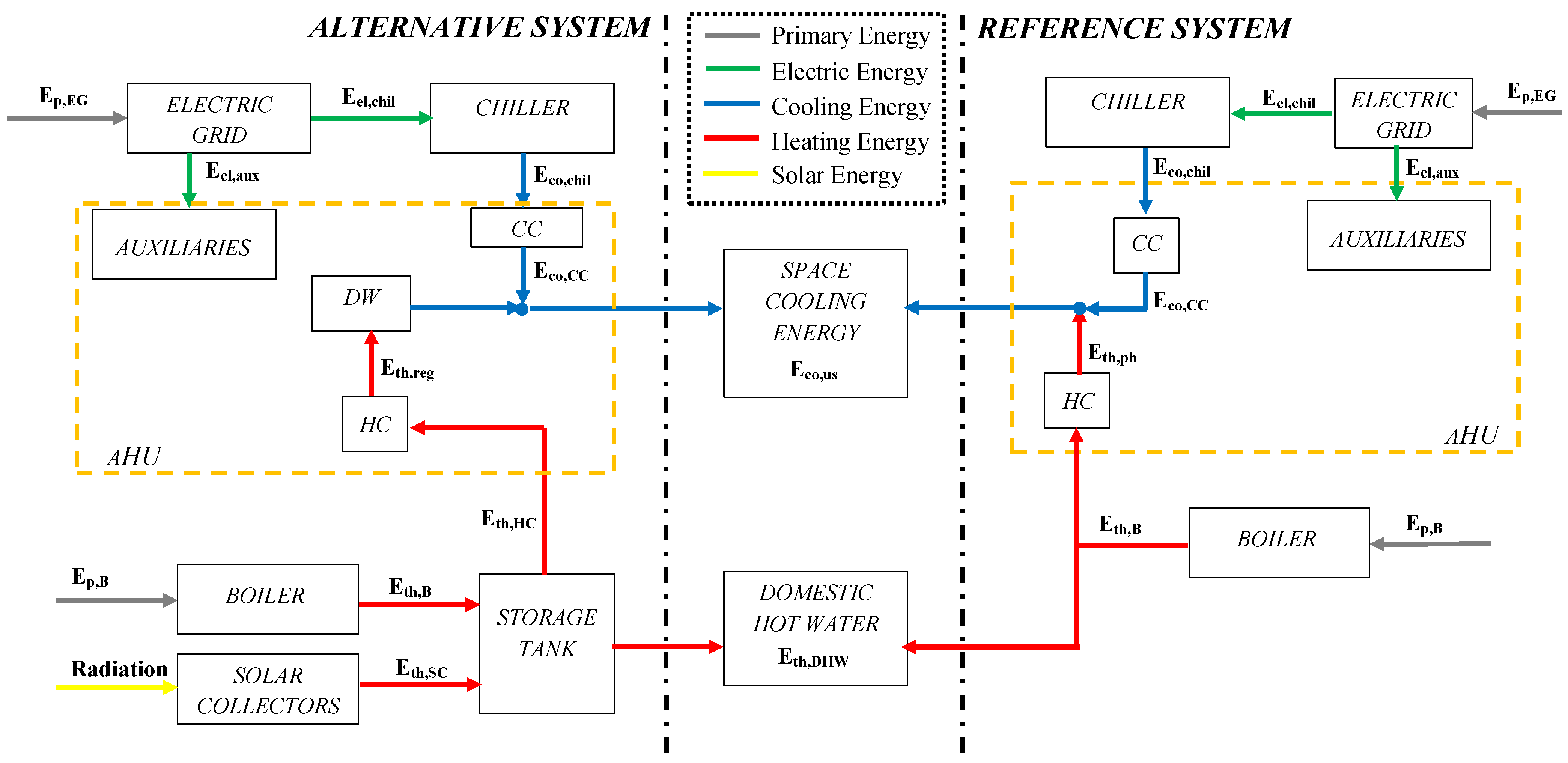
Figure 2, the main energy flows during summer of scenarios B (flat-plate collectors), C (evacuated tube collectors) and reference system (described in
Section 4.5), are shown. The only difference for scenario A (air collectors) is the absence of the thermal storage tank, while in scenario D (natural gas boiler) both the solar collectors and the storage tank are absent.
Thermal energy coming from solar collectors (Eth,SC) is used, with partial integration from a natural gas boiler (Eth,B), for the regeneration of the desiccant rotor (Eth,reg). Ep,B is the primary energy input of the boiler. Electric energy for the auxiliaries (Eel,aux) and for the chiller (Eel,chil), which produces chilled water (Eco,chil) for the CC, is drawn from the electric grid. Ep,EG is the primary energy input of the electric grid. Cooling energy is transferred from the chilled water to the process air in the CC (Eco,CC). Finally, energy for space cooling purposes (Eco,us) and for DHW (Eth,DHW) is provided to the building.
All year long, thermal energy coming from flat-plate and evacuated solar collectors and from the integration boiler is also used for DHW. In scenarios A (air collectors) and D (natural gas boiler) thermal energy for DHW purposes is provided by the natural gas boiler.
The four scenarios have been simulated and compared with a reference system, in terms of primary energy consumption, equivalent CO2 emissions and operating costs, by means of the commercial dynamic simulation software “TRNSYS 17.1” (Thermal Energy System Specialists, LLC, Madison, WI, USA), expanded with the additional “TESS” (Thermal Energy System Specialists) libraries. The simulations were performed on an annual basis, with a time step of 0.5 h.
To evaluate the performance of the systems, the climatic conditions of Naples (Italy) were taken into account with the corresponding climatic file.
The slope and the azimuth of the solar collectors surface was set to 20° (to optimize the summer operation of collectors, when the sun is high in the sky) and 0° (facing South), respectively, while the gross solar collectors surface was varied in the range 4–16 m2, with a step of 2 m2.
The building and the related cooling loads were simulated with the interface “TRNBuild” of TRNSYS and its “type 56”. In particular, depending on the cooling load of the building, humidity ratio and temperature of process air at supply is evaluated; accordingly, the calculated supply humidity ratio value is used as set-point for the DW, then the DW model calculates the required regeneration air temperature.
The corresponding thermal power related to DHW draw is evaluated considering the required water mass flow rate, the specific heat, the temperature of cold water from the mains entering the storage tank and the temperature of the hot water supplied to the end-user (45 °C).
Figure 2.
Energy flows during summer with active AHU: alternative system (scenarios B and C, flat-plate and evacuated tube collectors, respectively) and reference system.
Figure 2.
Energy flows during summer with active AHU: alternative system (scenarios B and C, flat-plate and evacuated tube collectors, respectively) and reference system.
The chiller is simulated by means of a performance map based model that evaluates its performance (both at full and partial load), in terms of cooling capacity and COP as a function of chilled water and ambient air dry-bulb temperatures. In particular, the model relies on two external data files: the former contains the capacity ratio (ratio between cooling capacity at current conditions to its nominal value) and performance ratio (ratio between COP at current conditions to its nominal value) as a function of chilled water and ambient air dry-bulb temperatures; the latter contains the data about the fraction of full load power (ratio between electric power input at current conditions to its nominal value) as a function of PLR (partial load ratio, actual cooling capacity to its nominal value). Data provided by the manufacturer were used to simulate the performance of the chiller, in terms of cooling capacity and energy performance [
13].
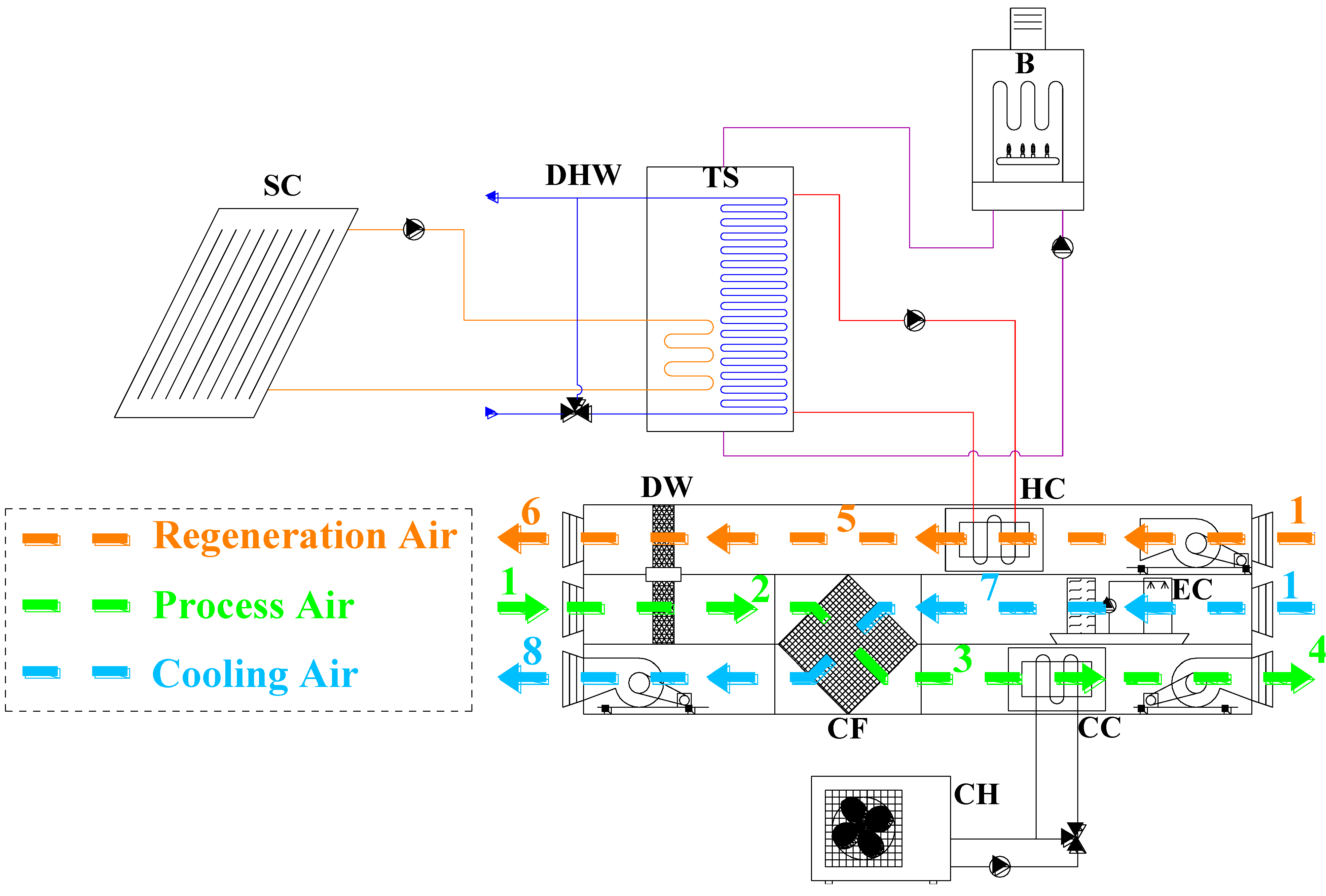
4.1. Scenario A (Air Collectors)
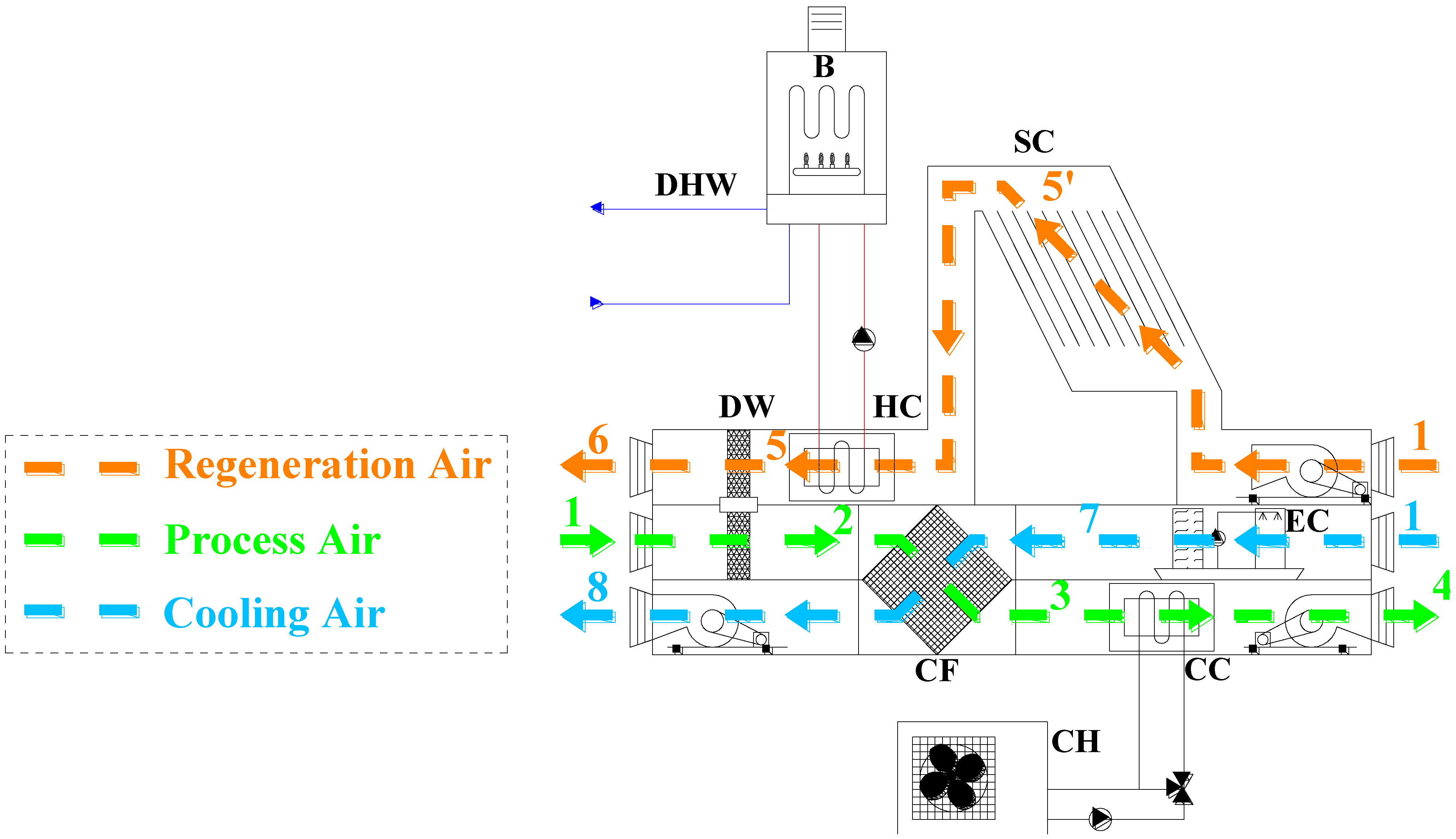
In this scenario, the AHU layout is different from that of
Figure 1, as the regeneration air directly crosses the solar air collectors (transformation 1–5’ in
Figure 3), and the storage tank is not present (
Figure 3). In fact, these types of collectors use air instead of a liquid as heat transfer fluid, with the advantage to avoid any problems of corrosion, freezing and fluid losses in the circuit. On the other hand, they have a reduced efficiency with respect to flat-plate and evacuated collectors, due to low heat exchange convective coefficients between air and the absorber plate; furthermore, air collectors do not allow thermal energy storage. The model of air collectors is calibrated by means of literature data [
14].
Thermal energy integration is provided by a natural gas boiler through the HC (transformation 5’–5 in
Figure 3). Regeneration air is then used to regenerate the DW (5–6). The transformations of process and cooling air are the same of
Figure 1, described in
Section 3.
Figure 3.
AHU layout for scenario A (air collectors).
Figure 3.
AHU layout for scenario A (air collectors).
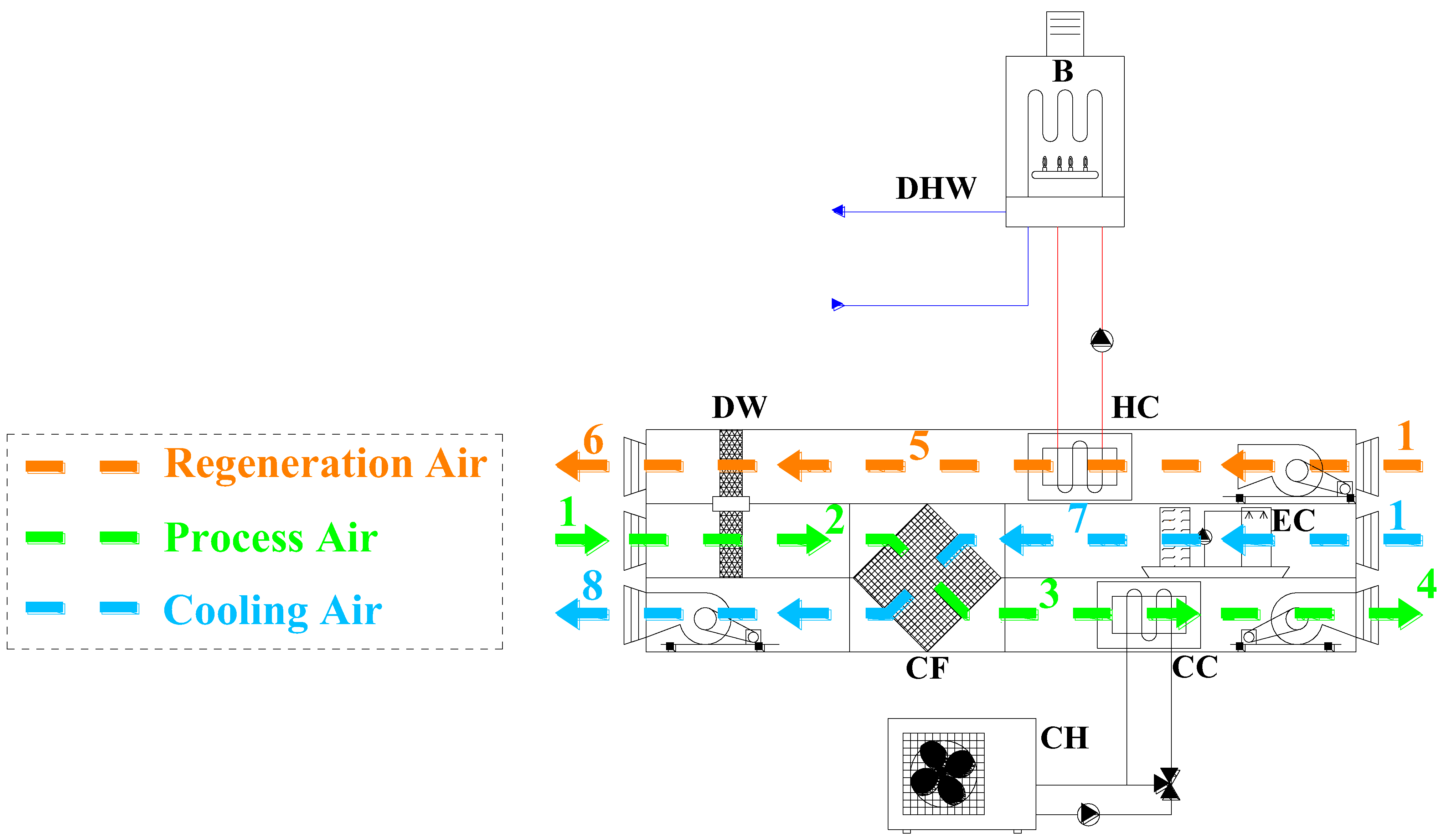
4.2. Scenario B (Flat-Plate Collectors)
Solar radiation is collected by means of flat-plate collectors, which heat up a water/glycol mixture. This mixture then transfers thermal energy to the fluid (water) in the storage tank, by means of the lower heat exchanger (
Figure 1). Flat-plate collectors model is calibrated by means of manufacturer data [
15]. The transformations of process, regeneration and cooling air are the same of
Figure 1, described in
Section 3.
4.3. Scenario C (Evacuated Tube Collectors)
This scenario is similar to the previous one (
Figure 1), the only difference is that evacuated solar collectors are used instead of flat-plate ones. The collectors’ model is calibrated by means of manufacturer data [
16]. The transformations of process, regeneration and cooling air are the same of
Figure 1, described in
Section 3.
4.4. Scenario D (Natural Gas Boiler)
Thermal energy to regenerate the silica-gel rotor in the desiccant-based air-handling unit is provided by a natural gas boiler (measured thermal efficiency equal to 82.8% [
11]), directly interacting with the HC in the regeneration path of the AHU (
Figure 4), to heat up the regeneration air (1–5). This is then used to regenerate the DW (5–6). The transformations of process and cooling air are the same of
Figure 1, described in
Section 3.
Figure 4.
AHU layout for scenario D (natural gas boiler).
Figure 4.
AHU layout for scenario D (natural gas boiler).
4.5. Reference System (RS)
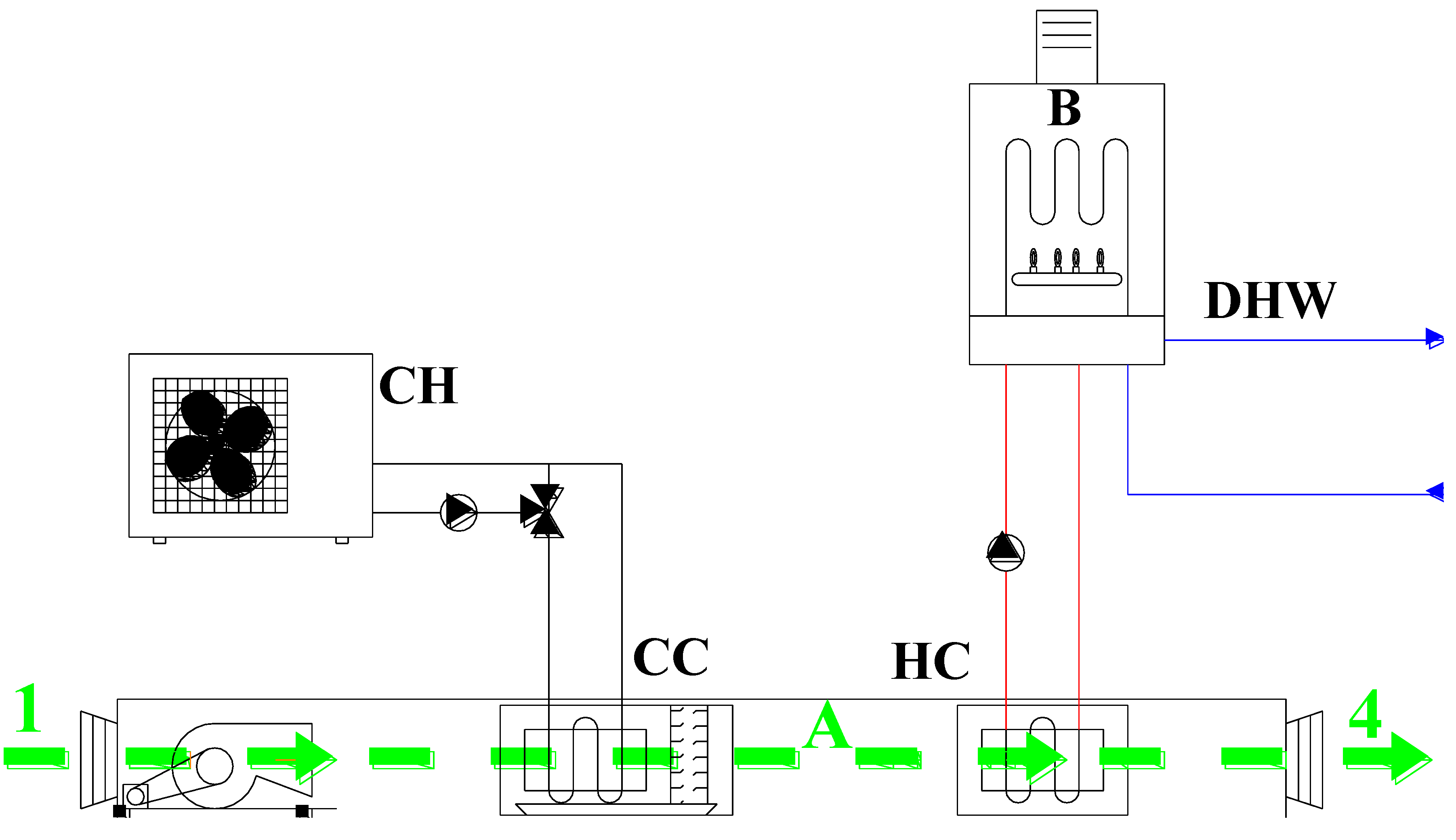
During the activation period of the air-conditioning system, a conventional AHU (
Figure 5) operates to reach the same supply condition of process air in the desiccant-based scenarios (state “4” in
Figure 1,
Figure 3 and
Figure 4), starting from the same outdoor conditions (state “1” in
Figure 1,
Figure 3 and
Figure 4) and with the same schedule. In particular, the process air is cooled below the dew point temperature and dehumidified by a cooling coil interacting with an electric compression chiller (process 1–A in
Figure 5); subsequently, it is heated up to the same supply temperature of the desiccant-based AHU by a heating coil interacting with a natural gas boiler (process A–4 in
Figure 5), which provides thermal energy for air post-heating (
Eth,ph in
Figure 2).
The conventional AHU is equipped with two pumps (one for the chiller and one for the boiler, 150 W each) and one fan (process air, 320 W).
Electric energy for the auxiliaries and for the chiller that produces chilled water for the cooling coil, is drawn from the electric grid. The chiller in the RS has to balance both the sensible and latent loads of process air, therefore it has a higher rated capacity (16.3 kW) and a lower rated COP (2.72) than the one in the desiccant-based scenarios, which has to manage the sensible load only. Thermal energy for air post-heating and for DHW is provided by the natural gas boiler.
The energy performance parameters of the electric grid, of the boiler, of the heating and cooling coils were assumed equal to the values in the desiccant-based scenarios (A to D), as described in next section.
Figure 5.
AHU layout for RS (reference system).
Figure 5.
AHU layout for RS (reference system).
4.6. Mathematical Models and Thermo-Economic Performance Assessment
The main parameters of the simulated solar collectors and of the main components of the AHU are reported in
Table 1. The models validation can be found in [
12] for the DCS components and in [
17] for the storage tank.
The energy performance of the desiccant-based systems (scenarios A to D) is evaluated in terms of annual avoided primary energy consumption, defined as:
where:
is the primary energy required on an annual basis by the desiccant scenarios.
The primary energy consumption of the RS,
, can be evaluated by Equation (2), using values of Eel,chil, Eel,aux and Eth,B referred to the reference system.
The environmental performance of the desiccant cooling systems are evaluated in terms of avoided equivalent CO
2 emissions:
are the equivalent CO
2 emissions on an annual basis of the desiccant scenarios. The equivalent CO
2 emissions of the RS,
, can be evaluated by Equation (4), using values of
Eel,chil,
Eel,aux and
Eth,B referred to the reference system.
Table 1.
Models used for solar collectors simulation and their main parameters.
Table 1.
Models used for solar collectors simulation and their main parameters.
| Component | Main parameters | Value | Units |
|---|
| Solar air collectors | Overall reflectance of the collector surface | 0.053 | - |
| Emissivity of the top and back surfaces of the collector | 0.85 | - |
| Emissivity of the top and bottom surface of the flow channel | 0.85 | - |
| Conductive resistance of the back insulation layer | 3.6 | m2·K/W |
| Conductive resistance of the absorber plate and structural layer | 0.036 | m2·K/W |
| Specific heat capacity of air | 1.007 | kJ/(kg·K) |
| Flat-plate solar collectors | Tested flow rate | 0.0213 | kg/(s·m2) |
| Intercept efficiency | 0.712 | - |
| Efficiency slope | 3.53 | W/(m2·K) |
| Efficiency curvature | 0.0086 | W/(m2·K2) |
| Fluid specific heat | 3.84 | kJ/(kg·K) |
| Evacuated solar collectors | Tested flow rate | 0.0213 | kg/(s·m2) |
| Intercept efficiency | 0.72 | - |
| Efficiency slope | 0.97 | W/(m2·K) |
| Efficiency curvature | 0.0055 | W/(m2·K2) |
| Fluid specific heat | 3.84 | kJ/(kg·K) |
| Desiccant wheel | Effectiveness ηF1 | 0.207 | - |
| Effectiveness ηF2 | 0.717 | - |
| Cross flow heat exchanger | Effectiveness | 0.446 | - |
| Humidifier | Saturation Efficiency | 0.551 | - |
| Natural gas boiler | Nominal thermal power | 24.1 | kW |
| Efficiency | 0.828 | - |
| Air-cooled chiller | Rated Capacity | 8.50 | kW |
| COP | 3.00 | - |
| Heating coil | Effectiveness | 0.842 | - |
| Cooling coil | Bypass fraction | 0.177 | - |
| Storage tank | Volume | 971 | L |
| Height | 2.04 | m |
| Tank loss coefficient | 1.37 | W/(m2·K) |
The previously described equations are general, but the numerical values of the parameters refer to the Italian situation. In particular:
is the average energy performance factor of Italian reference system for electricity supply, including transmission and distribution losses (ratio of electric energy output to primary energy input), assumed equal to 42.0% [
11];
is thermal efficiency of the boiler (equal to 82.8%, average value derived from experimental tests);
α is the specific equivalent CO
2 emission factor of electricity drawn from the grid (0.573 kg/kWh
el [
11]);
β is the specific equivalent CO
2 emission factor for primary energy related to natural gas consumption (0.207 kg/kWh
p [
11]);
Lower Heating Value (LHV) of natural gas equal to 9.52 kWh/Nm3;
Unitary cost of natural gas () in the range 0.759–0.903 €/Nm3, depending on the annual consumption and assuming a non-domestic application, e.g. an office;
Unitary cost of electricity () equal to 0.221 €/kWh;
Major cost of desiccant-based AHU with respect to conventional one is 10,000 €;
Investment cost of storage tank equal to 3000 €;
Investment cost of chiller: 3000 € for the SDCSs, 6000 € for the RS;
Specific cost of collectors: 275 €/m2 for air collectors; 360 €/m2 for flat-plate collectors; 602 €/m2 for evacuated collectors.
Furthermore, the Italian legislation recently introduced a mechanism to incentivize the use of renewable energy-based technologies to produce thermal energy [
18]. In the case of solar collectors, the annual incentive can be evaluated as:
where
Ia,tot is the annual economic incentive,
C is a valorization coefficient depending on the type of plant (equal to 255 €/m
2 for solar cooling systems) and
S is the gross solar collectors area. The incentive is not considered for air collectors.
The economic feasibility of the DCS is evaluated by means of the Simple Pay Back (
SPB) parameter, which evaluates the payback period of an investment, defined as:
where
EC is the extra cost of the DCS with respect to the RS.
OCDCS and
OCRS are the operating costs of the solar desiccant cooling and reference systems:
Incentives are considered only for scenarios B (flat-plate collectors) and C (evacuated tube collectors) for the first two years of operation. OCRS can be evaluated by Equation (7), using values of Eel,chil, Eel,aux and Eth,B referred to the reference system and adopting suitable values of
depending on the annual gas consumption. Incentives are obviously excluded for RS.
5. Results and Discussion
The regeneration of the desiccant rotor requires 7.69 MWh/year of thermal energy, while thermal energy for DHW is 4.58 MWh/year. In
Table 2, the contribution of solar collectors and of the integration boiler to the overall thermal energy requirement (
Figure 2) as well as the annual solar fraction (
SF) is shown for the three solar-based scenarios.
SF is the ratio between the useful thermal energy coming from solar collectors to the total thermal energy demand. Thermal energy for DW regeneration in scenario D and for DHW in scenarios A, D and RS are fully provided by the natural gas boiler.
The storage tank (scenarios B and C) determines average thermal energy losses of 12% on an annual basis.
Table 2.
Thermal energy supplied by solar collectors and by natural gas boiler.
Table 2.
Thermal energy supplied by solar collectors and by natural gas boiler.
| Collectors area | Scenario A (air collectors) | Scenario B (flat-plate collectors) | Scenario C (evacuated tube collectors) |
|---|
| Gross surface | Eth,SC | Eth,B | SF | Eth,SC | Eth,B | SF | Eth,SC | Eth,B | SF |
|---|
| [m2] | [MWh/year] | [-] | [MWh/year] | [-] | [MWh/year] | [-] |
| 4 | 1.19 | 12.3 | 0.088 | 2.76 | 10.6 | 0.207 | 3.16 | 10.2 | 0.237 |
| 6 | 1.72 | 11.7 | 0.128 | 4.03 | 9.22 | 0.304 | 4.72 | 8.46 | 0.358 |
| 8 | 2.19 | 11.1 | 0.165 | 5.23 | 7.87 | 0.399 | 6.23 | 6.76 | 0.480 |
| 10 | 2.64 | 10.6 | 0.199 | 6.35 | 6.62 | 0.490 | 7.70 | 5.13 | 0.600 |
| 12 | 3.03 | 10.1 | 0.231 | 7.45 | 5.40 | 0.580 | 9.19 | 3.08 | 0.749 |
| 14 | 3.36 | 9.72 | 0.257 | 8.45 | 4.28 | 0.664 | 10.6 | 1.84 | 0.852 |
| 16 | 3.64 | 9.40 | 0.279 | 9.42 | 3.19 | 0.747 | 12.1 | 0.248 | 0.980 |
In
Table 3, the values of the other main energy flows (
Figure 2) are reported. From the building simulation, the annual space cooling demand (
Eco,us) is 3.64 MWh/year. Cooling energy transferred from the chilled water to the process air (
Eco,CC) in the desiccant-based scenario is 2.50 MWh/year, therefore about 68.7% of cooling energy is provided by the cooling coil interacting with the chiller, and about 31.3% is provided by the desiccant system. The electric chiller in the desiccant-based scenarios requires 1.04 MWh/year of electricity, while the one in the RS has a higher electricity consumption (2.28 MWh/year). Electricity requirement of auxiliaries in the DCS is higher than that of the RS, due to higher electric power required by the auxiliaries of the desiccant-based AHU, and to the presence of the solar collectors pump in scenarios B (flat-plate collectors) and C (evacuated tube collectors). Primary energy input of electric grid and boiler can be evaluated with the related efficiency.
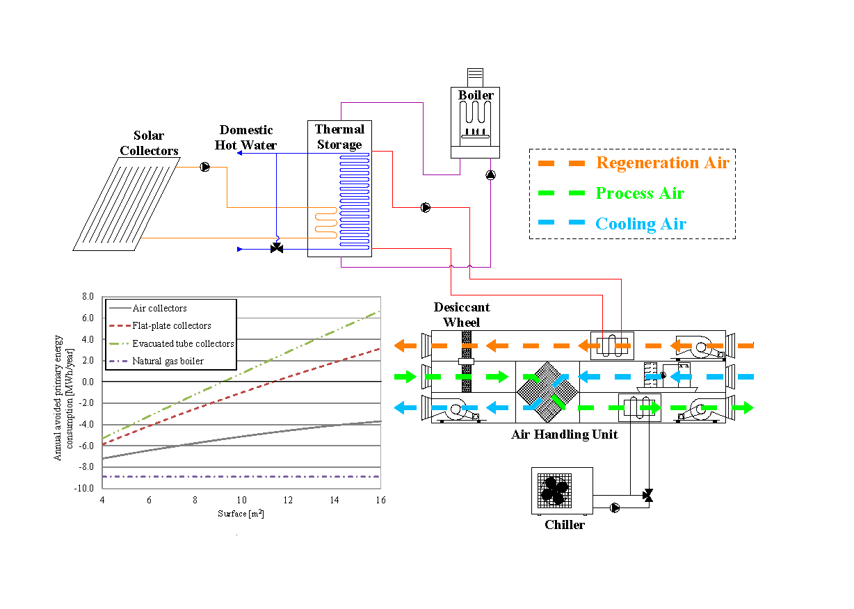
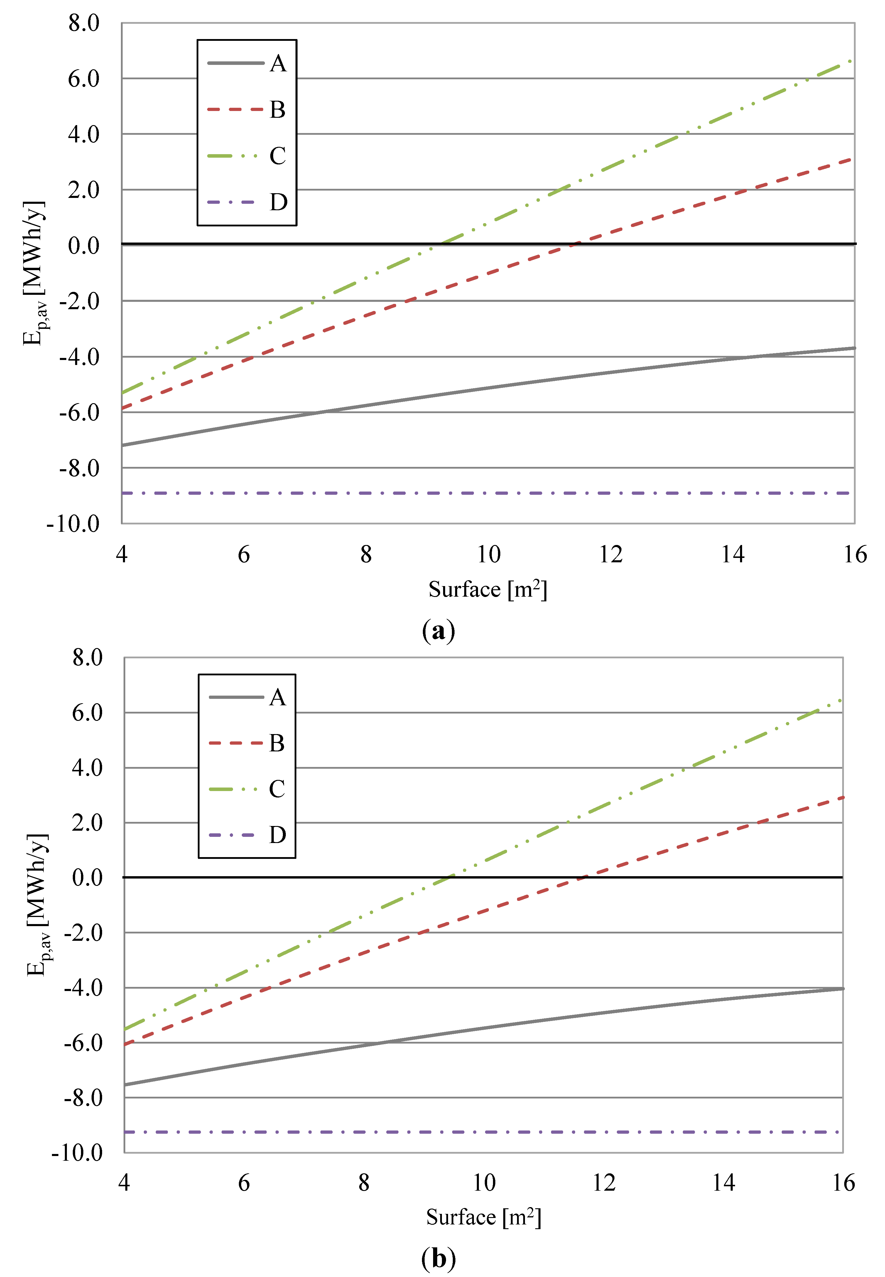
In
Figure 6a, the annual avoided primary energy consumption, in terms of fossil fuels, with respect to the RS, is shown as a function of the installed gross collectors surface, for the four desiccant-based scenarios. The RS has a primary energy consumption of 13.3 MWh/year. Energy performance rises with the solar surface and they are higher with evacuated collectors (scenario C), then they reduce more and more with flat-plate collectors (scenario B) and air collectors (scenario A).
Table 3.
Main energy flows of the investigated scenarios.
Table 3.
Main energy flows of the investigated scenarios.
| Energy flow | Scenario A (air collectors) | Scenario B (flat-plate collectors) | Scenario C (evacuated tube collectors) | Scenario D (natural gas boiler) | Reference system |
|---|
| Eco,us [MWh/year] | 3.64 | 3.64 | 3.64 | 3.64 | 3.64 |
| Eco,CC [MWh/year] | 2.50 | 2.50 | 2.50 | 2.50 | 4.94 |
| Eco,chil [MWh/year] | 3.00 | 3.00 | 3.00 | 3.00 | 5.94 |
| Eel,chil [MWh/year] | 1.04 | 1.04 | 1.04 | 1.04 | 2.28 |
| Eel,aux [MWh/year] | 1.34 | 1.62 | 1.62 | 1.34 | 0.81 |
| Eth,ph [MWh/year] | - | - | - | - | 0.29 |
Figure 6.
(a) Annual avoided primary energy consumption considering the current Italian situation and (b) the best available technology for electricity supply. Scenarios A (air collectors), B (flat-plate collectors), C (evacuated tube collectors) and D (natural gas boiler).
Figure 6.
(a) Annual avoided primary energy consumption considering the current Italian situation and (b) the best available technology for electricity supply. Scenarios A (air collectors), B (flat-plate collectors), C (evacuated tube collectors) and D (natural gas boiler).
The avoided primary energy consumption becomes positive for scenario C (evacuated tube collectors) and B (flat-plate collectors) only beyond a certain value of the surface (about 9 and 11 m2, respectively), while this never happens with air collectors (scenario A). Scenario D (natural gas boiler) has a higher primary energy consumption (about 8.91 MWh/year more) with respect to the RS, not depending on the solar surface.
If the best available technology (BAT) for the Italian reference system for electricity supply is assumed (
= 52.5%) rather than the previously defined average value, there is a slight reduction in
Ep,av in all investigated scenarios. In fact, the lower electricity demands of the desiccant-based scenario determine a reduced energy benefit when the electric grid becomes more efficient,
Figure 6b. When the BAT is considered, the RS has a primary energy consumption of 11.8 MWh/year.
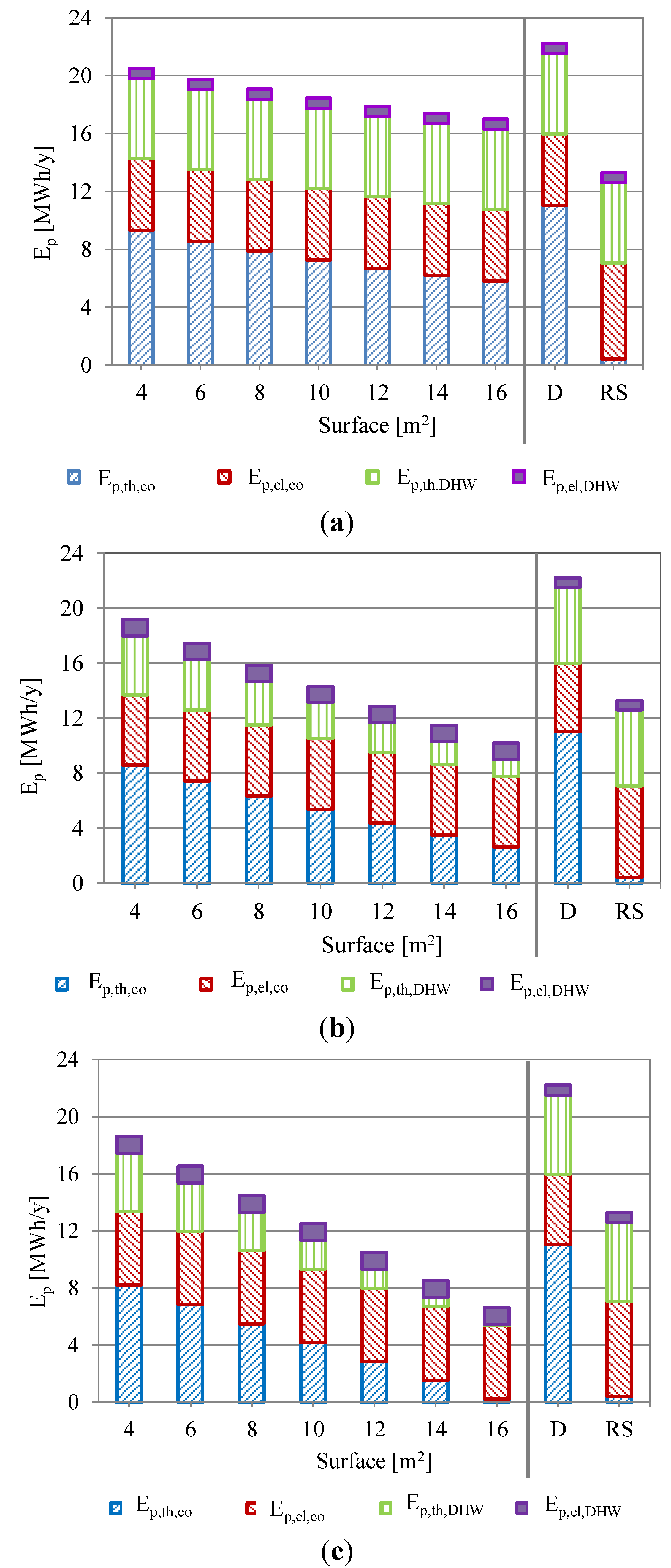
Simulated data are also analyzed in terms of primary energy demand related to electrical and thermal requirements for air-conditioning (
Ep,el,co and
Ep,th,co respectively) and primary energy demand related to electrical and thermal requirements for DHW purposes (
Ep,el,DHW and
Ep,th,DHW respectively). In
Figure 7 these primary energy demands for air collectors (scenario A,
Figure 7a), flat-plate collectors (scenario B,
Figure 7b) and evacuated tube collectors (scenario C,
Figure 7c) are shown as a function of the solar surface. The demands of scenario D (natural gas boiler) and RS are also reported in each part of
Figure 7, for an easier comparison with the SDCS.
Figure 7 confirms that scenario D is the worst option and that primary energy demand decreases when the absorbing surface increases for SDCS. This reduction is more evident in scenarios B and C, and it mainly depends on the reduction of the energy required by the integration boiler because of the collectors’ contribution in regeneration and DHW thermal energy. Solar air collectors are instead used for regeneration purposes only. It is also clear that the RS has higher electrical demands related to cooling operation while thermal energy for post-heating is very low. As regards DHW production, the primary energy demands associated to thermal energy is obviously lower in scenarios B and C. In scenario D, the regeneration and DHW thermal energy is fully provided by the natural gas boiler.
Comparing scenarios A (air collectors), B (flat-plate collectors) and C (evacuated collectors) with D (natural gas boiler), when the maximum collectors surface is considered, primary energy associated with the thermal energy for regeneration is covered by solar energy for about one half in scenario A, more than 2/3 in scenario B, and almost completely in scenario C, which becomes close to a completely solar-driven system.
Figure 7 can also be used to separately evaluate the contributions to the overall savings of DCS and DHW system.
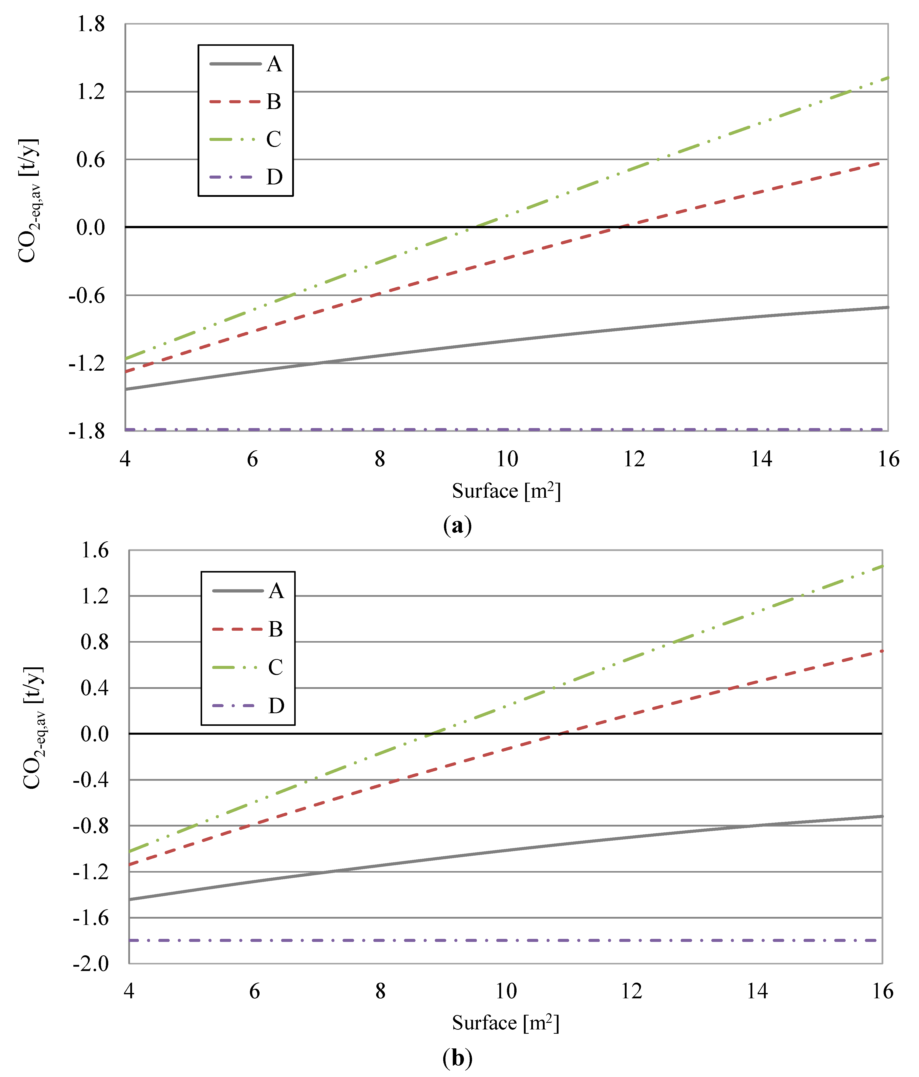
In
Figure 8a, the annual avoided emissions of the desiccant-based scenarios, with respect to the RS and as a function of the installed gross collector surface, are shown. The reference system has equivalent CO
2 emissions of 3.15 t/year. The same considerations done for
Figure 6a can be here repeated.
When the BAT for the electricity supply is taken into account, the specific equivalent CO
2 emission becomes α
= 0.394 kg/kWh
el. In this case, lower annual avoided emissions for all analyzed scenarios are achieved,
Figure 8b. When the BAT is considered, the RS has equivalent CO
2 emissions of 2.57 t/year.
If the contributions of thermal and electrical demands to the equivalent CO
2 emissions are evaluated, similarly to
Figure 7, the same considerations reported for the primary energy contributions (
Figure 7) can be done.
The avoided primary energy and emissions are not proportional to the surface (
Figure 6 and
Figure 8), because thermal energy production of the solar collectors is not proportional to the surface, as shown in
Table 2. In this work, the collectors are assumed to be connected in series, therefore an increase of the surface determines a rise in the fluid temperature and a consequent decrease of the collectors’ efficiency and of the energy production. This effect is more important for air collectors and less important for evacuated tube collectors, which have the worse and better insulation characteristics, respectively.
Figure 7.
Primary energy demands associated with electric and thermal demands. (a) scenarios A (air collectors), D (natural gas boiler) and RS (reference system); (b) scenarios B (flat-plate collectors), D and RS; (c) scenario C (evacuated tube collectors), D and RS.
Figure 7.
Primary energy demands associated with electric and thermal demands. (a) scenarios A (air collectors), D (natural gas boiler) and RS (reference system); (b) scenarios B (flat-plate collectors), D and RS; (c) scenario C (evacuated tube collectors), D and RS.
To separately evaluate the contribution of the energy demand for DHW and for the DCS to the overall primary energy saving, the analysis is now limited to the summer period only, excluding DHW requirement. In this case, the results of the comparison with the RS shown in
Figure 6 and
Figure 8 are unchanged for scenarios A (air collectors) and D (natural gas boiler), as they fully provide thermal energy for domestic hot water with a natural gas boiler, as occurs in the RS.
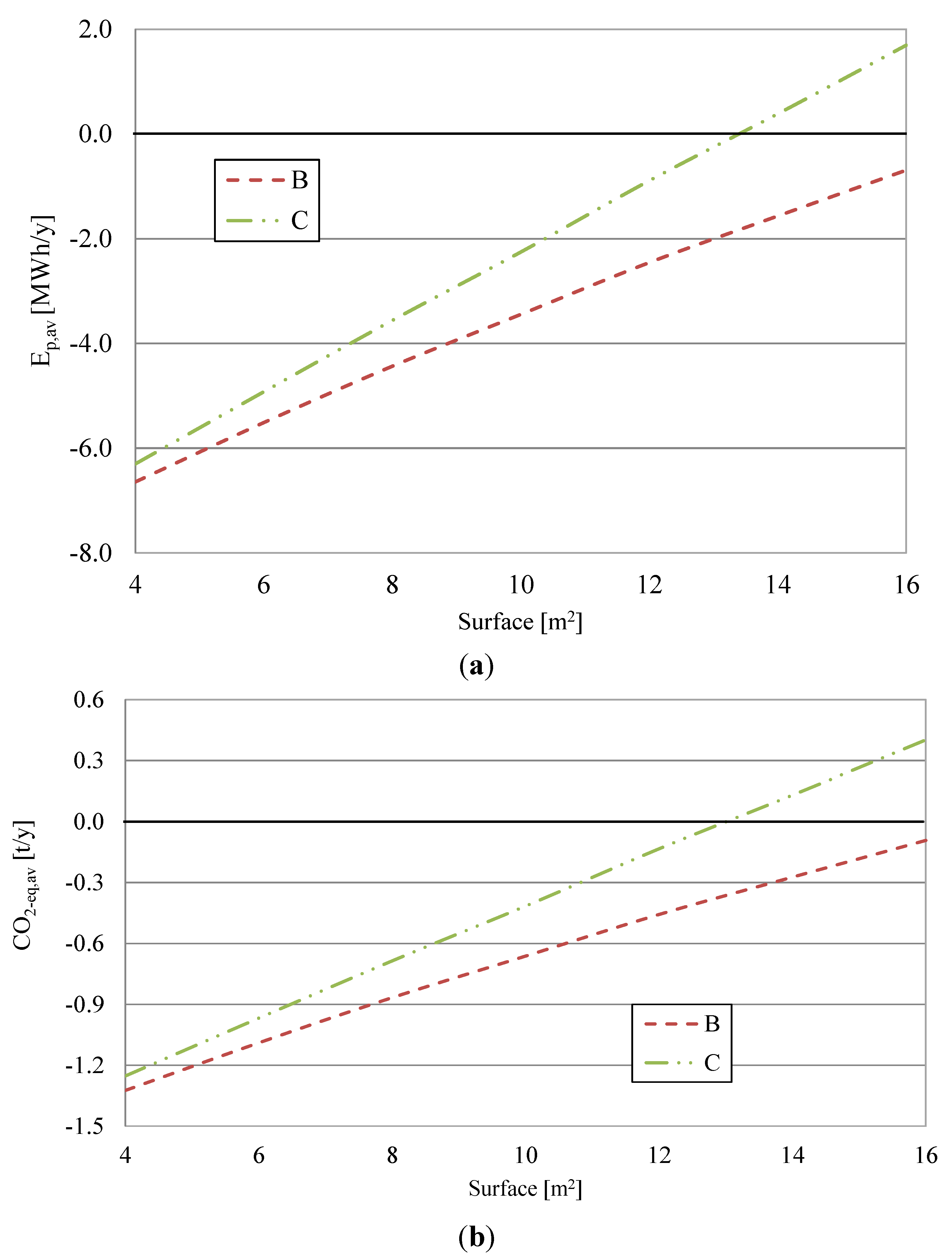
As regards scenarios B (flat-plate collectors) and C (evacuated tube collectors), the results excluding DHW demand are reported in
Figure 9. In this case, the reference system requires 7.08 MWh/year of primary energy, and releases 1.69 t/year of equivalent CO
2.
Figure 8.
(a) Annual avoided equivalent CO2 emissions considering the current Italian situation and (b) the best available technology for electricity supply. Scenarios A (air collectors), B (flat-plate collectors), C (evacuated tube collectors) and D (natural gas boiler).
Figure 8.
(a) Annual avoided equivalent CO2 emissions considering the current Italian situation and (b) the best available technology for electricity supply. Scenarios A (air collectors), B (flat-plate collectors), C (evacuated tube collectors) and D (natural gas boiler).
If DHW is excluded from the analysis, a decrease of the energy and emission performance for scenarios B and C is experienced. For example, the maximum avoided primary energy saving with 16 m
2 of evacuated tube collectors (scenario C) reduces to about 1.69 MWh/year, with respect to the value of
Figure 6a (6.69 MWh/year). This means that in the performed analysis, about 25% of the primary energy saving comes from the SDCS, but it should be also highlighted that the DCS is active only for about 25% of the yearly days, while DHW demand is present throughout the year. Nevertheless, in the best case (evacuated collectors, 16 m
2) the SDCS allows to obtain a primary energy saving and an equivalent CO
2 emissions saving of 24% with respect to the reference system, even considering only the energy demands of the desiccant-based AHU during summer.
Figure 9.
Energy and emissions analysis considering the current Italian situation and excluding DHW demands. (a) Avoided primary energy consumption and (b) avoided equivalent CO2 emissions. Scenarios B (flat-plate collectors) and C (evacuated tube collectors).
Figure 9.
Energy and emissions analysis considering the current Italian situation and excluding DHW demands. (a) Avoided primary energy consumption and (b) avoided equivalent CO2 emissions. Scenarios B (flat-plate collectors) and C (evacuated tube collectors).
Further considerations can be done considering the work in [
19] where, for the same user described in
Section 2, solar thermal energy is used for desiccant regeneration (in summer), for winter air-conditioning and for DHW. In particular, 4.93 MWh/year of thermal energy is required during winter by a conventional AHU to cover air-conditioning demands of the user. According to the simulations performed in this work, about 2.42 MWh/year of thermal energy can be provided by 16 m
2 of solar collectors (scenario C) during winter for air-conditioning purposes, while the shortage (2.51 MWh/year) is provided by the natural gas boiler. The reference system for comparison consists of the same conventional AHU, where all the required thermal energy is provided by the natural gas boiler. Electric energy requirements for the chiller and the auxiliaries during winter is 1.39 and 1.23 MWh/year, for scenario C and for RS, respectively, the former being slightly higher due to the solar collector pump. Considering the primary energy saving achieved in summer (1.69 MWh/year), the obtainable annual value is 4.23 MWh/year, which is about 26.5% of the primary energy consumption of the RS.
These results state that significant energy saving (about 24%) can be achieved also considering only the energy demands of the desiccant-based AHU during summer. However, to maximize the energy and emissions savings of SDCS, it is very important to increase the operating hours of the solar collectors, by using solar thermal energy both in summer for cooling purposes, and for other thermal energy demands (such as DHW or space heating) during the rest of the year.
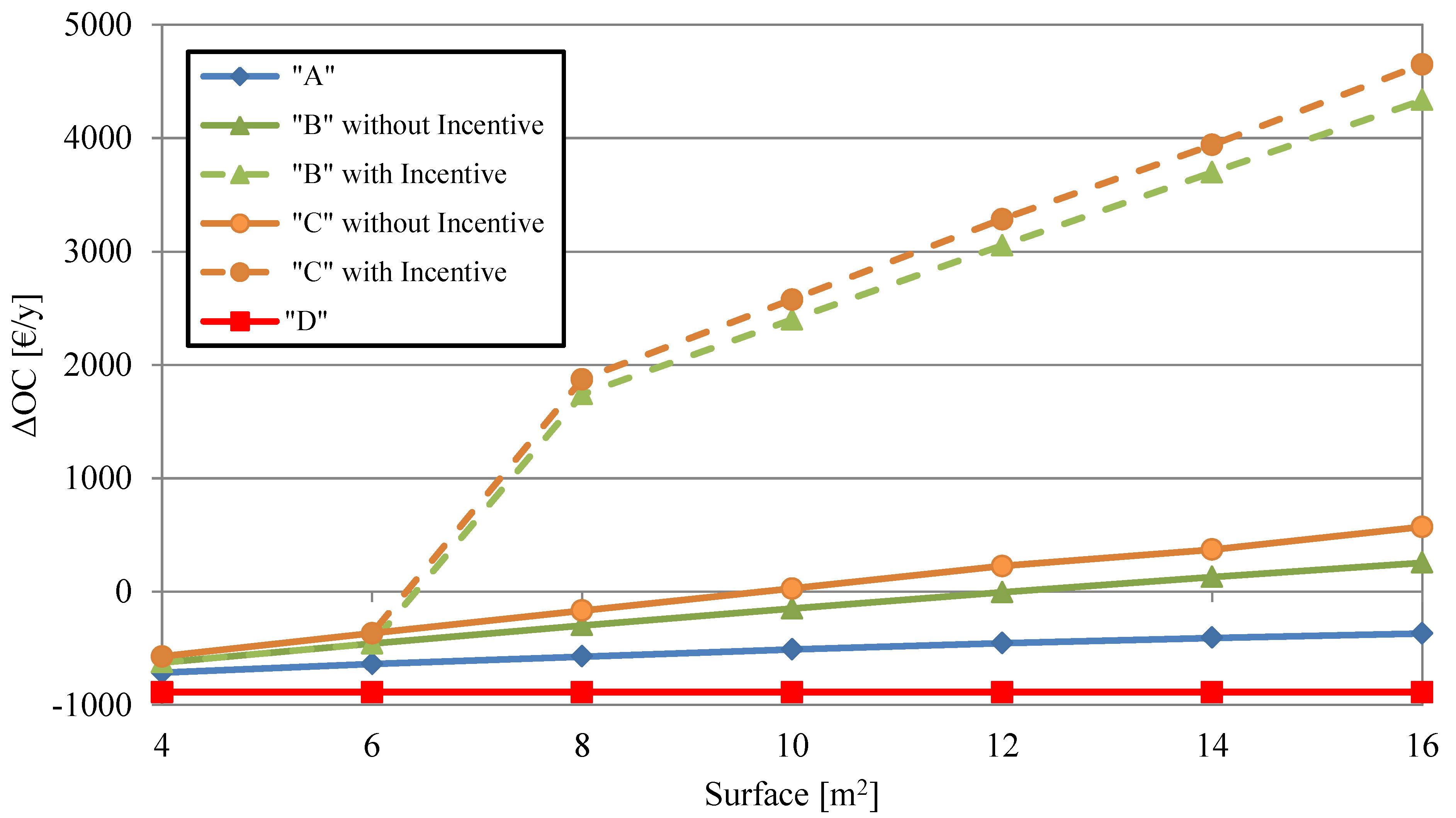
Figure 10 shows the differences in annual operating costs (Δ
OC) between the four DCS scenarios and the RS. Dashed lines represent the Δ
OC when economic incentives are considered for the first two years of operation for scenarios B (flat-plate collectors) and C (evacuated tube collectors). The Italian legislation [
18] requires that for SDCS the installed solar surface is at least 8 m
2 per 1000 m
3/h of process air, therefore the incentives were considered starting from that value of the installed surface.
Figure 10.
Differences of the annual operating costs between the four scenarios considered and the RS with and without incentives. Scenarios A (air collectors), B (flat-plate collectors, with and without incentive), C (evacuated tube collectors, with and without incentive), D (natural gas boiler).
Figure 10.
Differences of the annual operating costs between the four scenarios considered and the RS with and without incentives. Scenarios A (air collectors), B (flat-plate collectors, with and without incentive), C (evacuated tube collectors, with and without incentive), D (natural gas boiler).
The solid lines represent the ΔOC without incentives. In the cases with incentives, a reduction of the annual operating cost can be achieved starting from 8 m2 of solar surface, while without incentives a minimum surface of 12 and 10 m2 is required for scenario B (flat-plate collectors) and C (evacuated tube collectors), respectively. ΔOC curves increase with the surface in all SDCS. Scenarios A (air collectors) and D (natural gas boiler) have higher operating costs than RS.
The economic analysis states that the EC of the SDCS with respect to the RS is never recovered in scenarios A, B (both with and without incentive), C (without incentive) and D, considering a time horizon of 25 years. For the case with evacuated collectors (scenario C) with incentive, the economic feasibility is achieved only with 16 m2 of solar surface, which provide a SPB of 20 years and one month for the overall SDCS.
In the final selection process, scenario D is discarded, due to the lower techno-economic performance with respect to the RS; air collectors (scenario A) are excluded as well, due to the low energy and environmental performance, and to the fact that Italian legislation does not provide economic incentives for this type of collectors.
Given the small difference resulting from energy and environmental analysis between scenarios B and C, a proper trade-off between technical performance and investment cost could be achieved by selecting flat-plate collectors (scenario B), which is characterized by slightly lower energy and emissions savings with respect to evacuated collectors (scenario C), but also by a smaller investment cost. However, the economic payback is not achieved in scenario B, therefore the final choice should be 16 m2 of evacuated collectors (scenario C). This case achieves an avoided primary energy consumption of 6.69 MWh/year (a reduction of 50.2% with respect to the RS), avoided equivalent CO2 emissions of 1.57 t/year (−49.8% with respect to the RS), and a SPB of 20 years and on month, with an extra cost of about 19.6 k€.
6. Conclusions
In this paper, a model of a desiccant-based air-handling unit, calibrated and validated by means of experimental data, was implemented in a commercial dynamic simulation software, to simulate its interaction with solar collectors to provide thermal energy for regeneration of the desiccant wheel. Four different scenarios for desiccant wheel regeneration were investigated: A—air collectors; B—flat-plate collectors; C—evacuated collectors; D—natural gas boiler. In the solar desiccant-based scenarios (A to C), integration with a natural gas boiler is also taken into account. The collectors’ models were calibrated by means of data derived from technical and scientific literature.
Through the year, thermal energy coming from flat-plate and evacuated solar collectors is also used for domestic hot water preparation, which is provided by a natural gas boiler in scenario A (air collectors) and D (natural gas boiler).
These four scenarios were compared with a reference system, consisting of a conventional air-handling unit, based on cooling dehumidification and post-heating, by means of an electric chiller and a natural gas boiler, respectively. The latter device also provides thermal energy for DHW purposes. The comparison was based on energy, environmental and economic analysis, investigating the effect of the installed gross solar surface.
The main contributions of the performed study are:
- ➢
Energy and environmental savings increased with solar surface and the incentive made the solar desiccant system more attractive;
- ➢
Thermo-economic analysis allowed to evaluate in a quantitative way the achievable energy, emissions and operating costs savings;
- ➢
Thermo-economic comparison with the reference system is positive only beyond a certain value of the surface;
- ➢
Thermo-economic performance is not proportional to the solar surface, because thermal energy production of the solar collectors is not proportional to surface. The percentage increase of the performance is lower than the related percentage rise in the installed surface;
- ➢
In terms of economic performance, the increase of the surface determines two opposing effects, which are a rise in the operating costs difference and in the installation cost. Therefore, the overall effect of the surface increase on the pay-back period cannot be determined a-priori.
As a final selection and dimensioning of the solar desiccant cooling system, the best solution consists in 16 m2 of evacuated solar collectors. This solution allows to obtain, with respect to the reference system, a reduction of primary energy consumption and of the equivalent CO2 emissions of 50.2% and 49.8%, respectively, and it is the only case which achieves the economic pay-back of the investment, after 20 years and one month. A quite long pay-back period was achieved despite the economic incentive related to the promoting mechanism introduced by Italian legislation, because at the moment solar desiccant cooling systems, like many other solar cooling systems, are an expensive technology, and they cannot compete with other systems in terms of economic performance, especially with electrically-driven conventional units. Therefore a reduction of the installation cost from manufacturers, mainly of the desiccant-based air-handling unit, is strictly required, to exploit the energy and environmental advantages of desiccant cooling.


