Performance Evaluation of a Continuous Operation Adsorption Chiller Powered by Solar Energy Using Silica Gel and Water as the Working Pair

Abstract
: In the present study, dynamic analysis and performance evaluation of a solar-powered continuous operation adsorption chiller are introduced. The adsorption chiller uses silica gel and water as the working pair. The developed mathematical model represents the heat and mass transfer within the reactor coupled with the energy balance of the collector plate and the glass cover. Moreover, a non-equilibrium adsorption kinetic model is taken into account by using the linear driving force equation. The variation of solar radiation, wind speed, and atmospheric temperature along a complete cycle are considered for a more realistic simulation. Based on the case studied and the baseline parameters, the chiller is found to acquire a coefficient of performance of 0.402. The average thermal efficiency of the solar collector is estimated to be 62.96% and the average total efficiency approaches a value of 50.91%. Other performance parameters obtained are 363.8 W and 1.82 W/kg for the cooling capacity and the specific cooling power of the chiller, respectively. Furthermore, every 1 kg of silica gel inside the adsorption reactor produces a daily chilled water mass of 3 kg at a temperature of 10 °C. In addition, the cooling system harnesses 25.35% of the total available solar radiation and converts it to a cooling effect.1. Introduction
Adsorption-based cold production machine was developed and introduced before the vapor compression-based cooling systems. Adsorption cooling dates back to 1848, when Michael Faraday demonstrated a system utilizing ammonia and silver chloride as the working pair [1]. As reported by Critoph [2], In the early years of the twentieth century, Plank and Kuprianoff described a practical adsorption system that used methanol and active carbon as the working pair. However, the introduction of chlorofluorocarbons and the development of electrical compressors were the main reasons behind the decreasing activities on adsorption cooling researches for a considerable period of time till the oil crisis emerged in the 1970s [3,4]. Scientists have become aware about the traditional vapor compression machines’ major problems. These machines are dominating electricity consumers, and their operation causes high electricity peak loads [5]. In addition to the problems related to energy shortage, environmental pollution is another concern. Consequently, researches on adsorption cooling have gained a renaissance and in a strong direction.
Recently, a considerable number of researchers are focusing on the study of adsorption cooling machines [6–11]. The refrigerants used in these systems are environmentally friendly natural refrigerants like methanol [12–17], ammonia [18], and water [19–23]. The thermally operated compressor has no moving parts and could be driven by any low quality heat source like solar radiation, waste energy, as well as geothermal energy [3,4,24], and that is why solid adsorption refrigeration has tracked much interest and development over the world [6]. The avenue of development includes various designs of the system, newly developed adsorption pairs, advanced operating cycles, and different ways to enhance the system performance. Furthermore, solar-powered adsorption refrigeration (SAR) systems have attracted many researchers because the peak demands in cold coincide most of the time with the availability of the solar radiation [3]. The basic SAR system is a single adsorption bed integrated within a solar collector. The flat plate [25–29] as well as the compound parabolic concentrator [30–32] solar collectors have been used.
The literature is abundant with experimental work as well as theoretical investigation [13,15,16,18,20,33–35], although SAR systems are not yet widely commercialized and are not economically competitive with the conventional vapor compression cooling machines. Moreover, this technology is still in an early stage of development. A lot of research work is still needed for small scale as well as large scale applications in both civil and industrial settings. Enhanced performance, introduction of simple designs, reduced collector area, and developing dependable systems are crucial for bringing the SAR systems to practical applications.
One of the challenges for SAR systems is the intermittent operation due to the intermittent nature of solar radiation. Continuous cold production in SAR systems was developed and discussed by Hassan et al. [14]. The studied system is able to produce cold continuously throughout the 24 hours of the day. The presented continuous operation solar-powered adsorption refrigeration (CO-SAR) system was developed and modified in a further work [5]. The new system operates with the constant temperature adsorption refrigeration (CTAR) cycle [5,14]. The developed CTAR cycle differs from the traditional adsorption cooling thermodynamic cycle in both operation and processes. A thermodynamic steady-state analysis and an investigation of the influence of many system parameters of the CO-SAR system were introduced and discussed as well [5,14]. However, the dynamic simulation is an important tool that demonstrates the actual behavior of the system under consideration. In the present study, the dynamic analysis and performance evaluation of a chiller based on the CO-SAR system operation are introduced and discussed.
2. The Adsorption Bed Mathematical Model
In this section, the mathematical model that represents the coupled heat and mass transfer within the reactor is developed. The model is derived from basic principles of the mass and energy balance relations for the adsorption bed based on the control volume concept. The linear driving force equation that represents the non-equilibrium adsorption kinetics is merged with the derived equations.
The adsorbate volume fraction θ is given as a function of the concentration ratio as follows:
The LDF adsorption kinetic model [36] formulates the transient uptake for the adsorbent particles. The rate of adsorption d/dt is given by:
The adsorbate concentration ratio at equilibrium * is found from the Dubinin model as follows:
By substituting from Equation (3) into Equation (2):
A more compact form of Equation (6) can be expressed as follows:
Substituting from Equation (7) into the above equation, d/dt can be written as:
The total internal energy of the adsorption reactor is expressed as:
The time rate of change of the total internal energy of the control volume can be expressed as:
The mass balance equation for the adsorption reactor can be expressed as follows:
The evaporator flag, σev, equals 1 during the adsorption process and 0 otherwise. The condenser flag, σcon, equals 1 during the desorption process and 0 otherwise. Substituting from Equation (12) into the mass balance Equation (17), the following form is obtained:
The energy balance equation for the adsorption bed can be written as follows:
From Equation (15) and Equation (20), the energy balance Equation (19) takes the following form:
Equations (7), (18) and (22) represent the governing equations for the adsorption reactor.
3. Energy Balance of the Solar Collector
3.1. Collector Energy Balance during the Pre-Heating and Heating Processes
The total solar irradiation Ġt, which is harvested by an inclined surface, is the sum of the incident solar direct beam radiation Ġb, the sky diffuse solar radiation Ġd, and the ground diffuse solar reflection Ġg. This can be expressed as [37,38]:
This amount of radiation is reduced by the glass cover and absorber plate optical losses. The portion of the incident solar radiation that is absorbed by the absorbing plate Ġ is given by [39]:
The transmissivity–absorptivity product (τα)b, (τα)d and (τα)g are calculated by the procedure and sequence of equations described in [40–42]. Furthermore, the calculation method of Ġb, Ġd, and Ġg is based on the ASHRAE (American Society of Heating, Refrigerating and Air Conditioning Engineers) clear sky model, which is clearly explained in the literature [39].
The heat transfer from the bottom and the lateral surfaces of the solar collector are assumed negligible compared with the heat losses from the top surface of the collector. These losses account for the convection and radiation losses from the absorber plate in the upward direction through the glass cover to the ambient. For a single cover system, the energy balance for the glass cover is written as:
In the above equation, Q̇pl−gc and Q̇gc−amb represent the heat flow from the absorber plate to the glass cover and the heat flow from the glass cover to the atmosphere, respectively. These interactions of heat can be calculated from:
The first term in the right side of Equation (31) represents the effect of natural heat transfer between the plate and the cover. For an inclined collector at some angle from 0° to 75° to the horizontal plane, the Nusselt number u is expressed in terms of Rayleigh number a as follows:
The energy balance for the absorbing plate is given by the following equation:
3.2. Collector Energy Balance during the Isosteric Pre-Cooling and the Adsorption Processes
In the isosteric pre-cooling and the adsorption processes, the collector glass cover is opened and the adsorption reactor is allowed to cool by transferring heat to the ambient by convection and radiation. The energy balance for the glass cover in this case can be simply written as:
The overall losses heat transfer coefficient from the collector when its glass cover is opened pl−amb can be expressed as:
4. Numerical Solution
The governing equations that describe the heat and mass balance inside the adsorption reactor and those representing energy balance of the collector form a coupled non-linear system of first order differential equations. This system is solved in this study by using the Runge–Kutta fourth order explicit method. Furthermore, the tabulated values of the thermodynamic properties of the refrigerant are used. The partial derivatives of the refrigerant thermodynamic properties are evaluated by using an algorithm for the finite difference approximation of derivatives with arbitrary degree and order of accuracy [44]. Moreover, we consider the first operating cycle of the system. In other words, the adsorption reactor is considered in thermal equilibrium with the ambient at the beginning of the cycle. As a consequence, the initial temperature of the reactor is the same as the ambient temperature at beginning of the cycle. Based on the presented dynamic mathematical model, a Matlab computer program was constructed in order to simulate the system and evaluate its performance and operating parameters.
5. Case Study
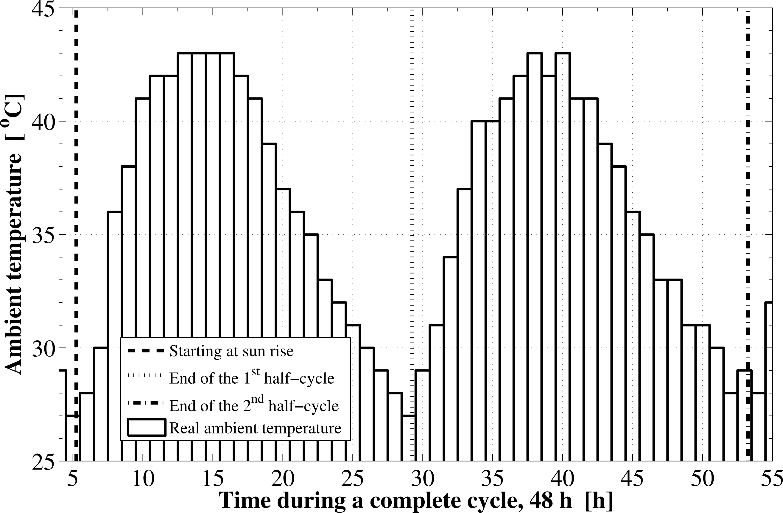
The developed computer code is used to dynamically simulate the operation and evaluate the performance of the CO-SAR chiller. This is done through studying a case in which the system operates during a certain day in the year and at a certain location. The selected location is Riyadh city in the Kingdom of Saudi Arabia (latitude 24.7° N, longitude 46.7° E). The system is considered to operate a full cooling cycle, which starts at the sunrise time of 1 July 2013 and ends at the sunrise time of 3 July 2013. In order to simulate the system in a realistic manner, the real time variations of the ambient temperature and the wind speed are taken in to account as well. Both the real hourly temperature and wind speed variations for Riyadh city during the specified operational period are taken from the historical records reported by the King Khaled International Airport weather station (OERK). The flat plate solar collector is 6 m2 in surface area and it has one glass cover of thickness 3 mm. The assembly of solar collector and adsorption reactor is placed in a horizontal position and is filled with the adsorption pair. Silica gel (porous volume 476 cm3/kg, particle density 700 kg/m3, and specific heat 921 J/kg·K) is used as the adsorbent and water is used as the refrigerant. The total mass of the silica gel within the bed is 100 kg/bed with a total porosity of 0.4. In addition, the evaporator temperature of the chiller is set to 10 °C, which corresponds to an evaporator pressure of 1.216 kPa. The condensation temperature of the refrigerant in the condenser is set to 50 °C, which corresponds to a condenser pressure of 12.26 kPa. Furthermore, the inlet temperature of the water to be cooled is set to 35 °C. The heat capacity effect of the adsorption reactor metallic casing in the present case is neglected. Other design parameter that were used in the current study are summarized in Table 1. Since both of the reactors work in the same schedule and out of phase, we consider only one of the adsorption reactors during a complete cycle in this investigation.
6. Results and Discussion
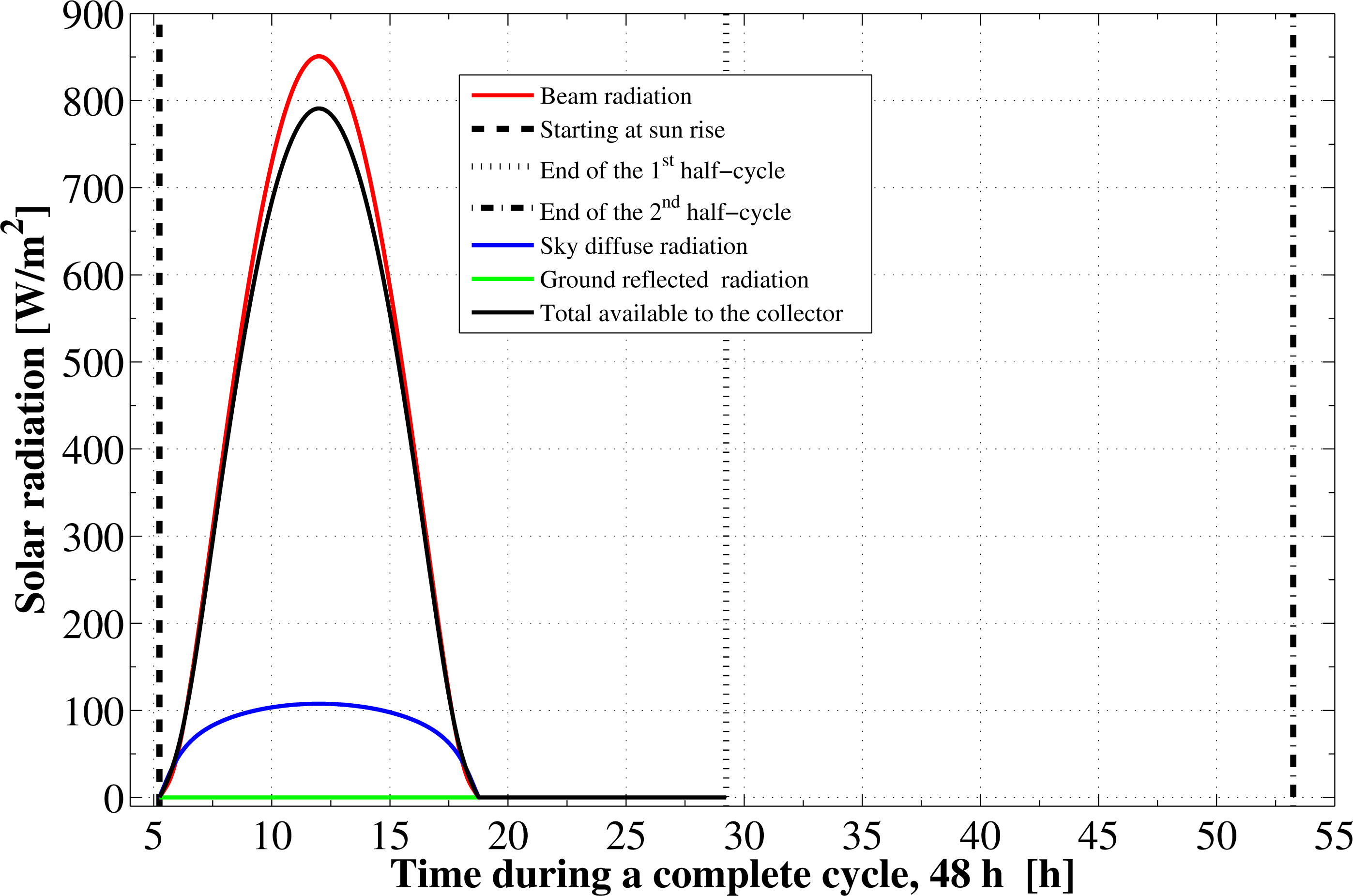
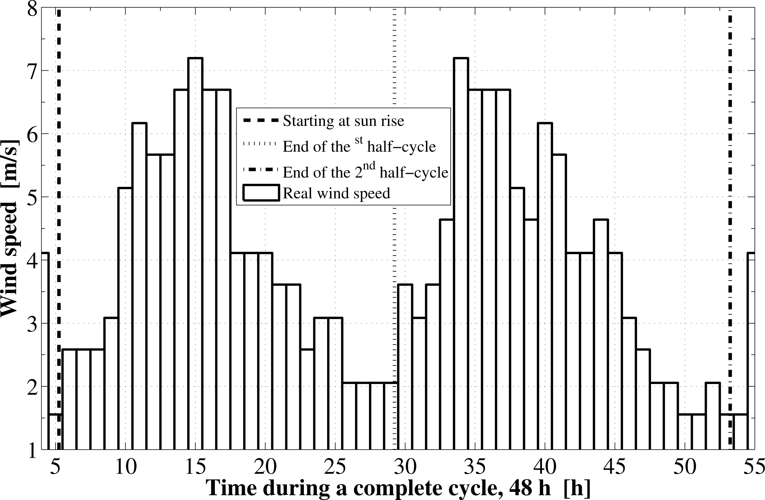
Based on the specified location and the operational dates, the components of the solar radiation incident on the flat plate as well as the cycle starting and ending times are determined. The instantaneous variations for these components are shown in Figure 1. The sun rises at about 5.24 h in the morning, which is the starting time of the first half-cycle. The sunset time is at about 18.75 h and the daylight length is 13.51 h. The second half-cycle starts at the sunrise time on the next day and ends at the sunrise on the third day. The components of solar radiation include the direct irradiation, the sky diffuse irradiation, and the ground reflected solar radiation. The total solar radiation absorbed by the solar collector absorbing plate is reduced by the amount of the transmittance-absorptance product. Furthermore, the real hourly variations in the ambient temperature as well as the wind velocity are plotted in Figures 2 and 3, respectively.
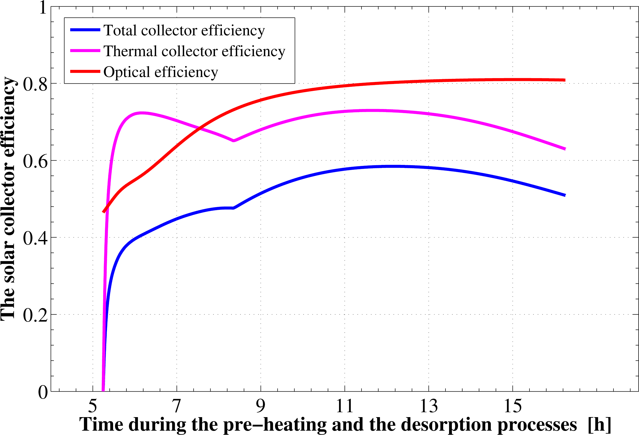
It is found from Figure 1 that the total available solar energy, between the sunrise to the sunset times in the first half cycle, is 27.318 MJ/m2. About 85% of this energy (23.22 MJ/m2) is in the form of direct radiation. The remaining portion is due to the sky diffuse part, which represents 15% (4.09 MJ/m2) of the total. Since the flat plate collector is in a horizontal place, there is no component for the ground reflection solar radiation. However, not all the 27.318 MJ/m2 energy is used. This is because the adsorption reactor heating and generation process ends about 2.5 h before the sunset time. Therefore, by the end of this process, the actual total solar energy available to the collector is only 25.56 MJ/m2. This means that about 1.75 MJ/m2 of the total available solar energy (based on complete day) is not used by the system. Moreover, due to the collector optical losses, an extra amount of nearly 4.89 MJ/m2 from the 25.56 MJ/m2 is lost. Therefore, the remaining part is determined to be equal to 20.67 MJ/m2. About 7.65 MJ/m2 of this part is lost also due to the thermal losses as well. Consequently, only 13.01 MJ/m2 of solar radiation is being transmitted to the adsorption bed as useful heat to provide activation of the refrigerant. Hence, the adsorption bed captures only 47.64% of the total solar radiation available during that specified day. The time variation of the solar collector thermal, optical, and total efficiencies during the pre-heating and desorption processes are plotted in Figure 4. The thermal efficiency of the solar collector shows a behavior that depends mainly on the driving potential for heat transfer between the continuously changing ambient temperature and glass cover temperatures. Its total average value is estimated to be 62.96%. The optical efficiency shows an increasing trend and attains an average value of about 80.86%. The instantaneous value of the optical efficiency changes depending on the solar beam incidence angle and the optical properties of the covering system as well as the absorber plate. The average total efficiency of the solar flat plate collector, which includes both optical as well as thermal losses, approaches a value of 50.91%. However, if we take the 2.4 h lag between the end of regeneration and the sunset time, the effective collector–adsorption bed integration is found to have a lower value, which is about 47.64%.
The solar adsorption chiller under the previously mentioned case study and baseline parameters is found to acquire a cooling coefficient of performance of 0.403. Other performance parameters obtained are 363.8 W and 1.82 W/kg for the cooling capacity and the specific cooling power of the chiller, respectively. The refrigeration effect produced inside the evaporator during a half-cycle period, which is 24 h, is estimated to be 31.43 MJ. This cooling effect corresponds to a total daily chilled water production of 300.39 kg at a temperature of 10 °C from water initially at a temperature of 35 °C. Therefore, every 1 kg of silica gel inside the adsorption reactor produces a daily chilled water mass of 3 kg at a temperature of 10 °C. Furthermore, the total refrigerant mass in the system is estimated to be 26.15 kg of water. About 96.52% of this mass, 25.24 kg, is an effective mass that circulates in the reactor-condenser-evaporator circuit and produces the refrigeration effect. In addition, the cooling system is found to harness about 19.18% of the total solar radiation available from the sun and convert it to cooling effect during the cycle.
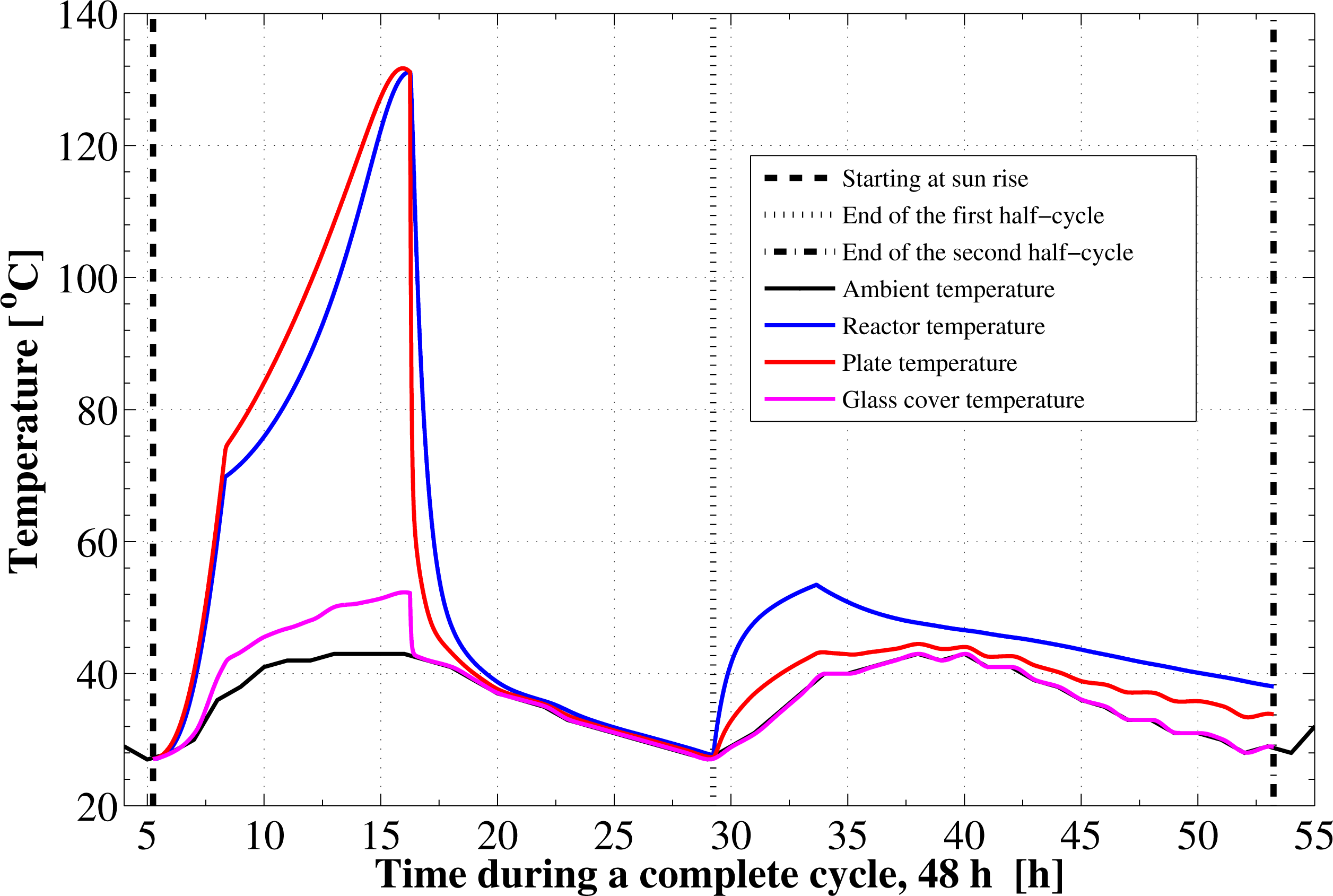
Figure 5 shows the development of the absorber plate, the glass cover, the adsorption reactor, and the ambient temperatures with time. During the isosteric heating phase, the collector absorber plate continues to absorb the continuously increasing solar radiation and a rapid increase in the plate temperature as well as the adsorption bed temperature is noticed. It can be seen that, the reactor preheating process takes about 3.09 h. In this process the temperature elevates from 27 °C to 69.78 °C at which the adsorbent starts the generation phase. Due to the endothermic behavior of the desorption process during the refrigerant generation phase, the rate of temperature increase at beginning of this process is lower than the preheating process. The reactor generation phase takes about 7.92 h. After that, a noticed decreasing rate in the reactor temperature takes place due to the cooling process that continues for 12.98 h till the first half cycle ends. The adsorption bed stays for long time period, about 12.98 h, during the isosteric cooling process in a thermal equilibrium with the surrounding environment. Therefore its temperature follows the ambient temperature variation, Figure 5. Then, at the beginning of the adsorption process that takes place during the next whole day, the bed temperature increases sharply due to releasing the latent heat of adsorption, Figure 5. After this point, there is some temperature difference between the reactor and the ambient, which acts as a driving potential to reject the waste heat. Due to the ambient temperature variation, the adsorption process is not isothermal. It is also noticed that the final state of the reactor is not the same as the starting point of the cycle. At the end state the reactor has a temperature of 38 °C, which is higher than the starting temperature. In addition, the final ambient temperature is different and the reactor does not have time to reach thermal equilibrium with the ambient.
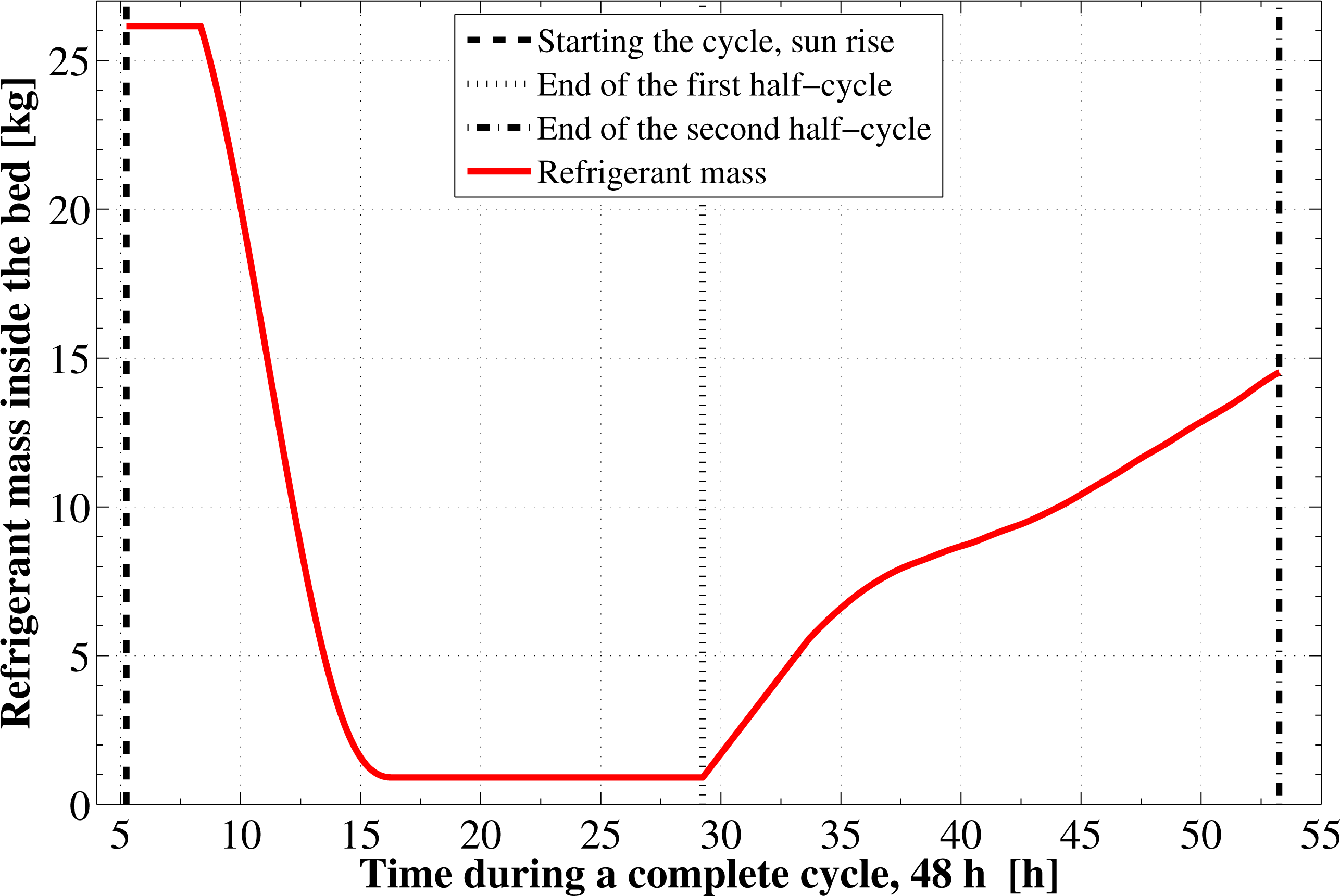
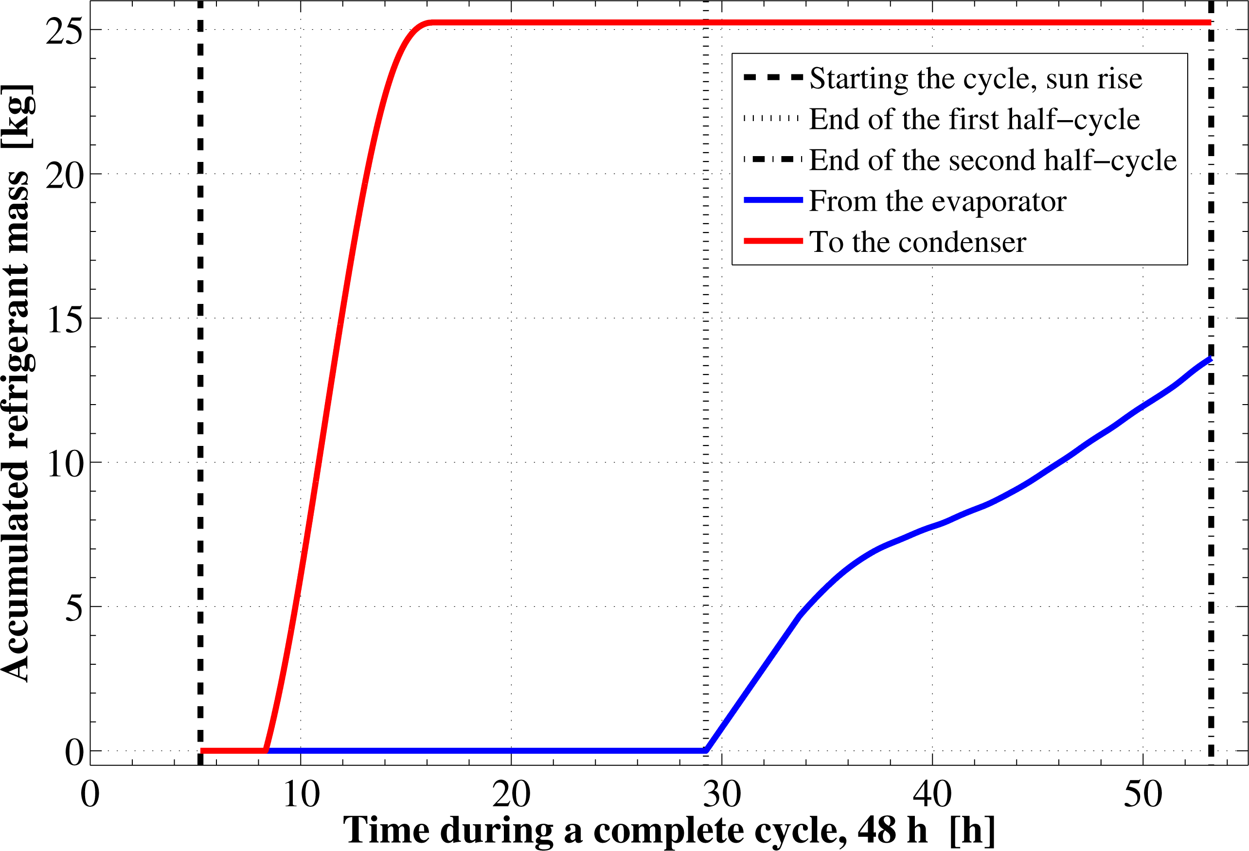
Figure 6 shows the time development of the refrigerant total mass inside the adsorption reactor. The refrigerant mass has its maximum value of 26.15 kg in the isosteric pre-heating and its minimum value of 0.91 kg during the isosteric pre-cooling process. As shown in the figure, the final refrigerant mass content inside the reactor at the cycle end, 14.51 kg, is less than that at beginning of the cycle. This is due to the different final conditions of the adsorption bed. It is also noticed from the figure that, the rate at which the refrigerant desorbs is higher than the rate at which it is adsorbed. Moreover, the desorption process occurs at almost a constant rate. Figure 7 demonstrates the time integration of the refrigerant mass desorbed from the reactor as well as adsorbed within the reactor. This figure shows a difference of 11.63 kg from the refrigerant between the initial and the final state. This difference will affect the cycle operation and performance parameters during the next operating cycle of the system.
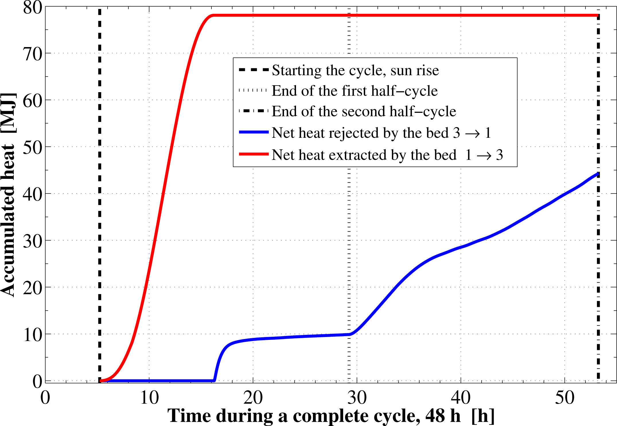
Figure 8 depicts the time integration of the heat absorbed by the adsorption reactor during the pre-heating and generation processes as well as the time integration of the waste heat rejected to the ambient during the pre-cooling and the adsorption processes. By the end of the desorption process, the total amount of heat absorbed by the adsorption bed is found to be 78.1 MJ. About 10.3% of this heat is consumed in the pre-heating process. The total amount of heat rejected by the adsorption bed is found to be 44.26 MJ. About 22.3% of this heat is rejected during the sensible pre-cooling isosteric process.
7. Conclusions
A silica gel solid adsorption chiller that operates on the constant temperature adsorption cycle is studied. The solar energy is used to drive the system through the assembly of the flat plate and the adsorption bed. Moreover, dynamic simulation and performance assessment of the chiller are discussed. The mathematical analysis is based on the coupled heat and mass transfer within the reactor coupled with the energy balance for the collector plate and glass cover. The model considers the non-equilibrium adsorption kinetics and the instantaneous variations of solar radiation. Furthermore, the actual variations of wind speed and ambient temperature along the day for Riyadh city were used in the simulation. The cooling coefficient of performance of the simulated chiller is found to be 0.402 and the solar COP is determined as 0.25. The system provides daily chilled water production of 3 kg at a temperature of 10 °C per kg of the adsorbent. This shows a good potential of the solar-powered adsorption chiller for cold production technology in the Kingdom of Saudi Arabia.
Acknowledgments
The author of this paper would like to thank Alfaisal University, Riyadh, Kingdom of Saudi Arabia for providing the support to complete this work. The present study is accomplished under the Internal Research Grant IRG2014 Project No. 208260101147.
Nomenclature
| A | surface area (m2) |
| C | specific heat (J kg−1 K−1) |
| D | constant in Dubinin equation (–) |
| E | characteristic energy of adsorption (J kg−1) |
| Ġ | solar radiation (W m−2) |
| h | specific enthalpy (J kg−1) |
| 𝒽w | wind convection heat transfer coefficient (W m−2 K−1) |
| m | mass (kg) |
| Ngc | number of glass covers (–) |
| u | Nusselt number (–) |
| n | constant in Dubinin equation (–) |
| r | Prandtl number (–) |
| P | pressure (Pa) |
| Q̇ | heat (W) |
| R | gas constant (J kg−1 K−1) |
| a | Rayleigh number (–) |
| T | temperature (K) |
| U | internal energy (J) |
overall heat transfer coefficient (W m−2 K−1) | |
| V | volume (m3) |
| w | wind speed (m s−1) |
| Wo | the maximum adsorption capacity (m3 kg−1) |
adsorbed phase concentration ratio (kg kg−1) | |
| * | adsorbed phase concentration ratio at equilibrium (kg kg−1) |
| Greek Symbols | |
|---|---|
| α | absorptance (–) |
| β̃ | tilt angle of the flat plate solar collector (°) |
| ∊ | emissivity (–) |
| θ | adsorbate phase volume fraction (–) |
| ρ | density (kg m−3) |
| ε | total porosity of the solid adsorbent medium (–) |
| (τα) | transmissivity–absorptivity product (–) |
| Subscripts | |
|---|---|
| a | adsorbate phase |
| amb | ambient or atmospheric |
| b | bed |
| con | condenser or condensation |
| ev | evaporator |
| g | gas or vapor phase |
| gc | glass cover |
| pl | absorber plate of the solar collector |
| sat | saturation |
| sm | solid or porous media |
| w | wind |
Abbreviations
| COP | coefficient of performance |
| CO-SAR | continuous operation solar-powered adsorption refrigeration |
| CTAR | constant temperature adsorption refrigeration |
| SAR | solar-powered adsorption refrigeration |
| LDF | linear driving force |
- Conflicts of InterestThe authors declare no conflict of interest.
References
- Meunier, F.; Douss, N. Performance of adsorption heat pumps. Active carbon-methanol and zeolite-water pairs. ASHRAE Trans 1990, 2, 267–274. [Google Scholar]
- Critoph, R.E. An ammonia carbon solar refrigerator for vaccine cooling. Renew. Energy 1994, 5, 502–508. [Google Scholar]
- Hassan, H.Z.; Mohamad, A.A. A review on solar cold production through absorption technology. Renew. Sustain. Energy Rev 2012, 16, 5331–5348. [Google Scholar]
- Hassan, H.Z.; Mohamad, A.A. A review on solar-powered closed physisorption cooling systems. Renew. Sustain. Energy Rev 2012, 16, 2516–2538. [Google Scholar]
- Hassan, H.Z.; Mohamad, A.A. Thermodynamic analysis and theoretical study of a continuous operation solar-powered adsorption refrigeration system. Energy 2013, 61, 167–178. [Google Scholar]
- Wang, D.; Zhang, J.; Yang, Q.; Li, N.; Sumathy, K. Study of adsorption characteristics in silica gel–water adsorption refrigeration. Appl. Energy 2014, 113, 734–741. [Google Scholar]
- Umair, M.; Akisawa, A.; Ueda, Y. Performance evaluation of a solar adsorption refrigeration system with a wing type compound parabolic concentrator. Energies 2014, 7, 1448–1466. [Google Scholar]
- Uyun, A.S.; Miyazaki, T.; Ueda, Y.; Akisawa, A. High performance cascading adsorption refrigeration cycle with internal heat recovery driven by a low grade heat source temperature. Energies 2009, 2, 1170–1191. [Google Scholar]
- Qasem, N.A.A.; El-Shaarawi, M.A.I. Improving ice productivity and performance for an activated carbon/methanol solar adsorption ice-maker. Sol. Energy 2013, 98, 523–542. [Google Scholar]
- Habib, K.; Choudhury, B.; Chatterjee, P.K.; Saha, B.B. Study on a solar heat driven dual-mode adsorption chiller. Energy 2013, 63, 133–141. [Google Scholar]
- Lu, Z.; Wang, R.; Xia, Z.; Gong, L. Experimental investigation adsorption chillers using micro-porous silica gel-water and compound adsorbent-methanol. Energy Convers. Manag 2013, 65, 430–437. [Google Scholar]
- Hassan, H.Z.; Mohamad, A.A.; Bennacer, R. Simulation of an adsorption solar cooling system. Energy 2011, 36, 530–537. [Google Scholar]
- Hassan, H.Z. Energy analysis and performance evaluation of the adsorption refrigeration system. ISRN Mech. Eng 2013, 2013, 704340. [Google Scholar]
- Hassan, H.Z.; Mohamad, A.A.; Al-Ansary, H.A. Development of a continuously operating solar-driven adsorption cooling system: Thermodynamic analysis and parametric study. Appl. Therm. Eng 2012, 48, 332–341. [Google Scholar]
- Hassan, H.Z. A solar powered adsorption freezer: A case study for Egypt’s climate. Int. J. Energy Eng 2013, 3, 21–29. [Google Scholar]
- Hassan, H.Z. Effect of parameters variation on the performance of adsorption based cooling systems. Int. Rev. Mech. Eng 2013, 7, 24–37. [Google Scholar]
- Wang, R.Z.; Jia, J.P.; Teng, Y.; Zhu, Y.H.; Wu, J.Y. Study on a new solid adsorption refrigeration pair, active carbon fiber-methanol. ASME J. Sol. Energy Eng 1997, 119, 214–218. [Google Scholar]
- Louajari, M.; Mimet, A.; Ouammi, A. Study of the effect of finned tube adsorber on the performance of solar driven adsorption cooling machine using activated carbon-ammonia pair. Appl. Energy 2011, 88, 690–698. [Google Scholar]
- Marlinda; Uyun, A.S.; Miyazaki, T.; Ueda, Y.; Akisawa, A. Performance analysis of a double-effect adsorption refrigeration cycle with a silica gel/water working pair. Energies 2010, 3, 1704–1720. [Google Scholar]
- Wang, D.C.; Zhang, J.P. Design and performance prediction of an adsorption heat pump with multi-cooling tubes. Energy Convers. Manag 2009, 50, 1157–1162. [Google Scholar]
- Rahman, A.F.M.; Ueda, Y.; Akisawa, Y.; Miyazaki, T.; Saha, B.B. Design and performance of an innovative four-bed, three-stage adsorption cycle. Energies 2013, 6, 1365–1384. [Google Scholar]
- Uyun, A.S.; Miyazaki, T.; Ueda, Y.; Akisawa, A. Experimental investigation of a three-bed adsorption refrigeration chiller employing an advanced mass recovery cycle. Energies 2009, 2, 531–544. [Google Scholar]
- Anyanwu, E.E.; Ogueke, N.V. Thermodynamic design procedure for solid adsorption solar refrigerator. Renew. Energy 2005, 30, 81–96. [Google Scholar]
- Abu-Hamdeh, N.H.; Alnefaie, K.A.; Almitani, K.H. Design and performance characteristics of solar adsorption refrigeration system using parabolic trough collector: Experimental and statistical optimization technique. Energy Convers. Manag 2013, 74, 162–170. [Google Scholar]
- Li, M.; Wang, R.Z.; Xu, Y.X.; Wu, J.Y.; Dieng, A.O. Experimental study on dynamic performance analysis of a flat-plate solar solid-adsorption refrigeration for ice maker. Renew. Energy 2002, 27, 211–221. [Google Scholar]
- Li, M.; Huang, H.B.; Wang, R.Z.; Wang, L.L.; Yang, W.M.; Cai, W.D. Study on intermittent refrigeration phenomenon for solar solid adsorption refrigeration. Appl. Therm. Eng 2005, 25, 1614–1622. [Google Scholar]
- Lemmini, F.; Errougani, A. Building and experimentation of a solar powered adsorption refrigerator. Renew. Energy 2005, 30, 1989–2003. [Google Scholar]
- Lemmini, F.; Errougani, A. Experimentation of a solar adsorption refrigerator in Morocco. Renew. Energy 2007, 32, 2629–2641. [Google Scholar]
- Hildbrand, C.; Dind, P.; Pons, M.; Buchter, F. A new solar powered adsorption refrigerator with high performance. Sol. Energy 2004, 77, 311–318. [Google Scholar]
- Headley, O.S.; Kothdiwala, A.F.; McDoom, I.A. Charcoal-methanol adsorption refrigerator powered by a compound parabolic concentrating solar collector. Sol. Energy 1994, 53, 191–197. [Google Scholar]
- González, M.I.; Rodríguez, L.R. Solar-powered adsorption chiller with CPC collection system: Collector design and experimental results. In Proceedings of ISES World Congress 2007; Springer-Verlag: Berlin, Germany, 2007; pp. 916–920. [Google Scholar]
- González, M.I.; Rodríguez, L.R. Solar powered adsorption refrigerator with CPC collection system: Collector design and experimental test. Energy Convers. Manag 2007, 48, 2587–2594. [Google Scholar]
- Zhai, X.Q.; Wang, R.Z. Experimental investigation and performance analysis on a solar adsorption cooling system with/without heat storage. Appl. Energy 2010, 87, 824–835. [Google Scholar]
- Karamanis, D.; Vardoulakis, E. Application of zeolitic materials prepared from fly ash to water vapor adsorption for solar cooling. Appl. Energy 2012, 97, 334–339. [Google Scholar]
- Luo, H.; Wang, R.; Dai, Y. The effects of operation parameter on the performance of a solar–powered adsorption chiller. Appl. Energy 2010, 87, 3018–3022. [Google Scholar]
- Glueckauf, E. Theory of chromatography. Part 10. Formula for diffusion into spheres and their application to chromatography. Trans. Faraday Soc 1955, 51, 1540–1551. [Google Scholar]
- Spencer, J.W. Fourier series representation of the position of the sun. Search 1971, 2, 172. [Google Scholar]
- Iqbal, M. An Introduction to Solar Radiation; Academic Press: New York, NY, USA, 1983. [Google Scholar]
- Duffie, J.A.; Beckman, W.A. Solar Engineering of Thermal Processes, 3rd ed; John Wiley & Sons: New York, NY, USA, 2006. [Google Scholar]
- Saraf, G.R.; Hamad, F.A.W. Optimum tilt angle for a flat plate solar collector. Energy Convers. Manag 1988, 28, 185–191. [Google Scholar]
- Eldighidy, S.M.; Taha, I.S. Optimum mass flow rate of water in a flat plate solar collector coupled with a storage tank and an organic Rankine cycle power loop. Sol. Energy 1983, 31, 455–461. [Google Scholar]
- Brandemuehl, M.J.; Beckman, W.A. Transmission of diffuse radiation through CPC and flat plate collector glazings. Sol. Energy 1980, 24, 511–513. [Google Scholar]
- Klein, S.A. Calculation of flat-plate collector loss coefficients. Sol. Energy 1975, 17, 79–80. [Google Scholar]
- Hassan, H.Z.; Mohamad, A.A.; Atteia, G.E. An algorithm for the finite difference approximation of derivatives with arbitrary degree and order of accuracy. J. Comput. Appl. Math 2012, 236, 2622–2631. [Google Scholar]


| Symbol | Parameter | Value | Unit |
|---|---|---|---|
| Glass cover | |||
| Cg | specific heat of the glass cover | 820 | [J · kg−1 · K−1] |
| Ngc | number of the glass cover | 1 | [−] |
| ρg | density of the glass cover. | 2515 | [kg · m−3] |
| tg | glass cover thickness. | 0.003 | [m] |
| ni | index of refraction | 1.526 | [−] |
| αg | extinction coefficient | 16.1 | [m−1] |
| εg | emissivity. | 0.88 | [−] |
| lgab | air gap thickness. | 0.03 | [m] |
| Absorber plate | |||
| stainless steel, black chrome selective coating | |||
| Cpl | specific heat of the plate | 500 | [J · kg−1 · K−1] |
| ρpl | density of the plate | 7850 | [kg · m−3] |
| αpl | absorptivity of the plate | 0.95 | [−] |
| εpl | emissivity of the plate | 0.05 | [−] |
| tpl | plate thickness | 0.002 | [m] |
| Silica gel adsorbent | |||
| Cs | specific heat of the adsorbent | 921 | [J · kg−1 · K−1] |
| ks | thermal conductivity of the adsorbent | 0.198 | [W · m−1 · K−1] |
| ρs | particle density of the adsorbent. | 700 | [kg · m−3] |
| Wo | coefficient of Dubinin equation | 489 × 10−6 | [m3 · kg−1] |
| n | coefficient of Dubinin equation | 1.35 | [−] |
| k1 | coefficient of LDF equation | 1.318 × 10⁵ | [−] |
| k2 | coefficient of LDF equation | 5.051 × 10³ | [−] |
| Vb | bed volume | 0.1587 | [m3] |
| ε | bed porosity | 0.4 | [−] |
© 2014 by the authors; licensee MDPI, Basel, Switzerland This article is an open access article distributed under the terms and conditions of the Creative Commons Attribution license (http://creativecommons.org/licenses/by/3.0/).
Share and Cite
Hassan, H.Z. Performance Evaluation of a Continuous Operation Adsorption Chiller Powered by Solar Energy Using Silica Gel and Water as the Working Pair. Energies 2014, 7, 6382-6400. https://doi.org/10.3390/en7106382
Hassan HZ. Performance Evaluation of a Continuous Operation Adsorption Chiller Powered by Solar Energy Using Silica Gel and Water as the Working Pair. Energies. 2014; 7(10):6382-6400. https://doi.org/10.3390/en7106382
Chicago/Turabian StyleHassan, Hassan Zohair. 2014. "Performance Evaluation of a Continuous Operation Adsorption Chiller Powered by Solar Energy Using Silica Gel and Water as the Working Pair" Energies 7, no. 10: 6382-6400. https://doi.org/10.3390/en7106382