A Counter-Current Heat-Exchange Reactor for the Thermal Stimulation of Hydrate-Bearing Sediments

Abstract
:1. Introduction
2. Results and Discussion
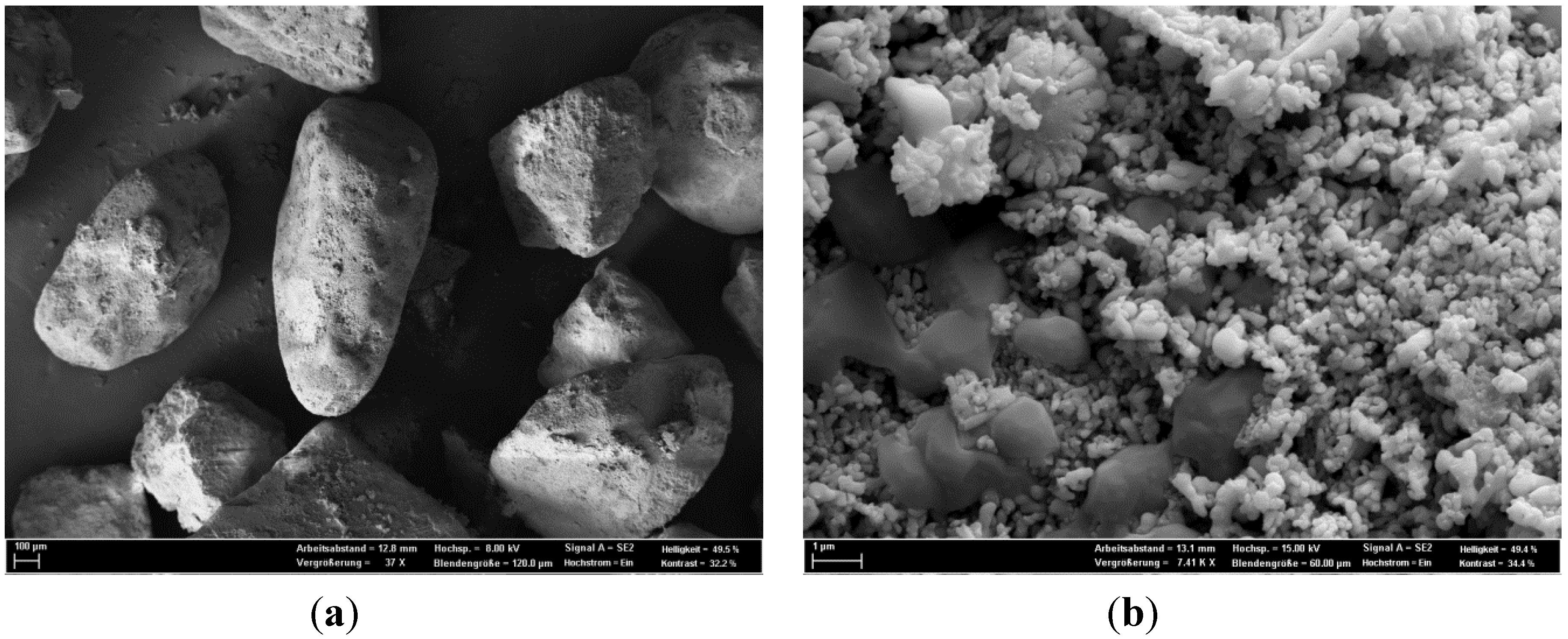
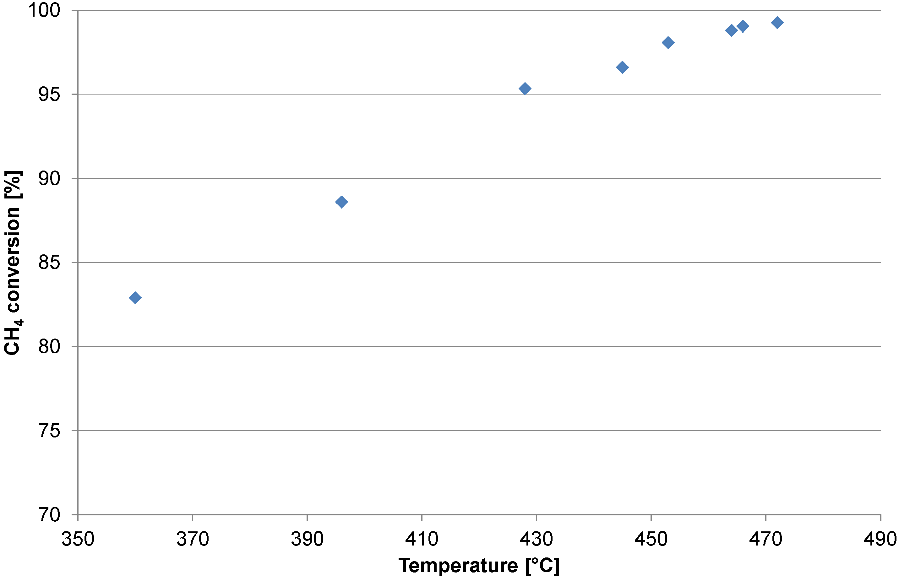
2.1. Catalyst Test


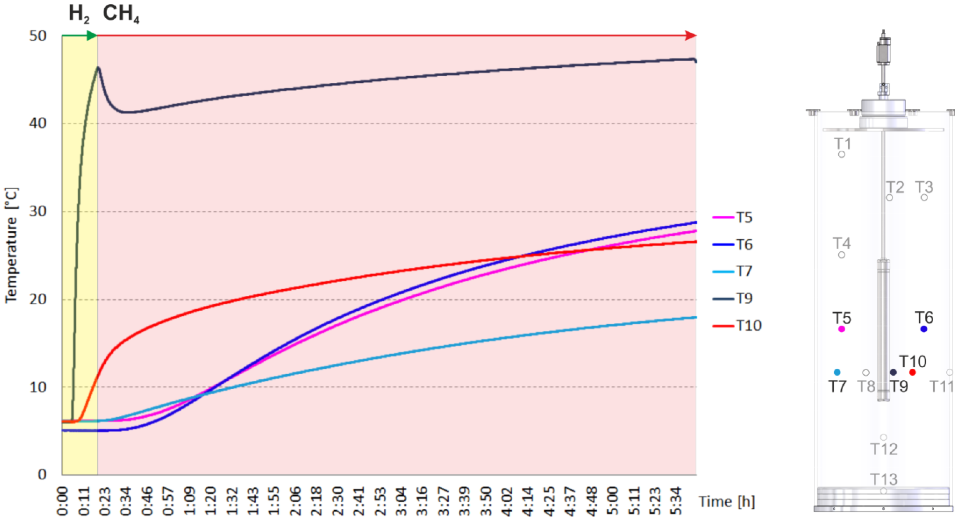
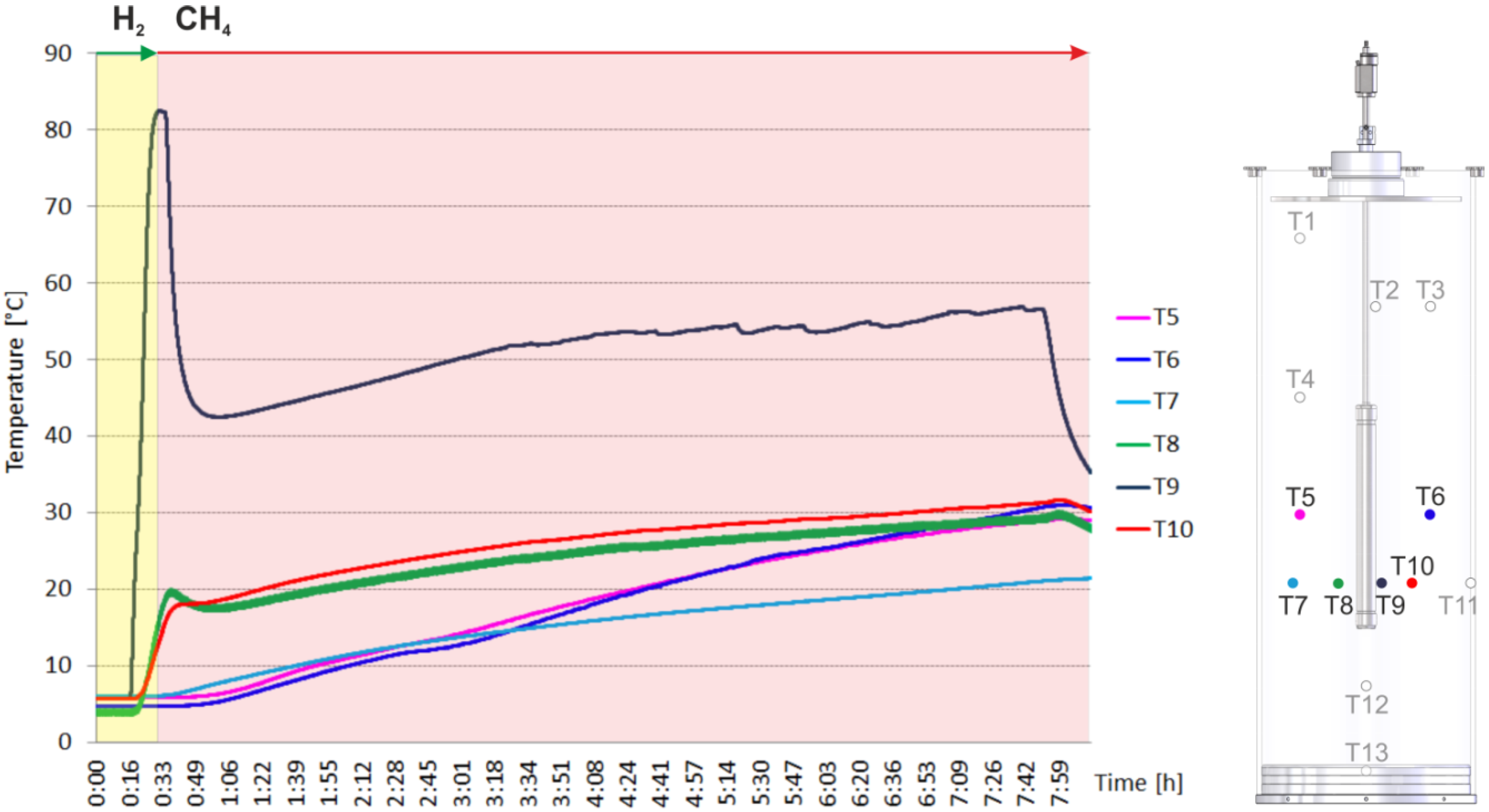
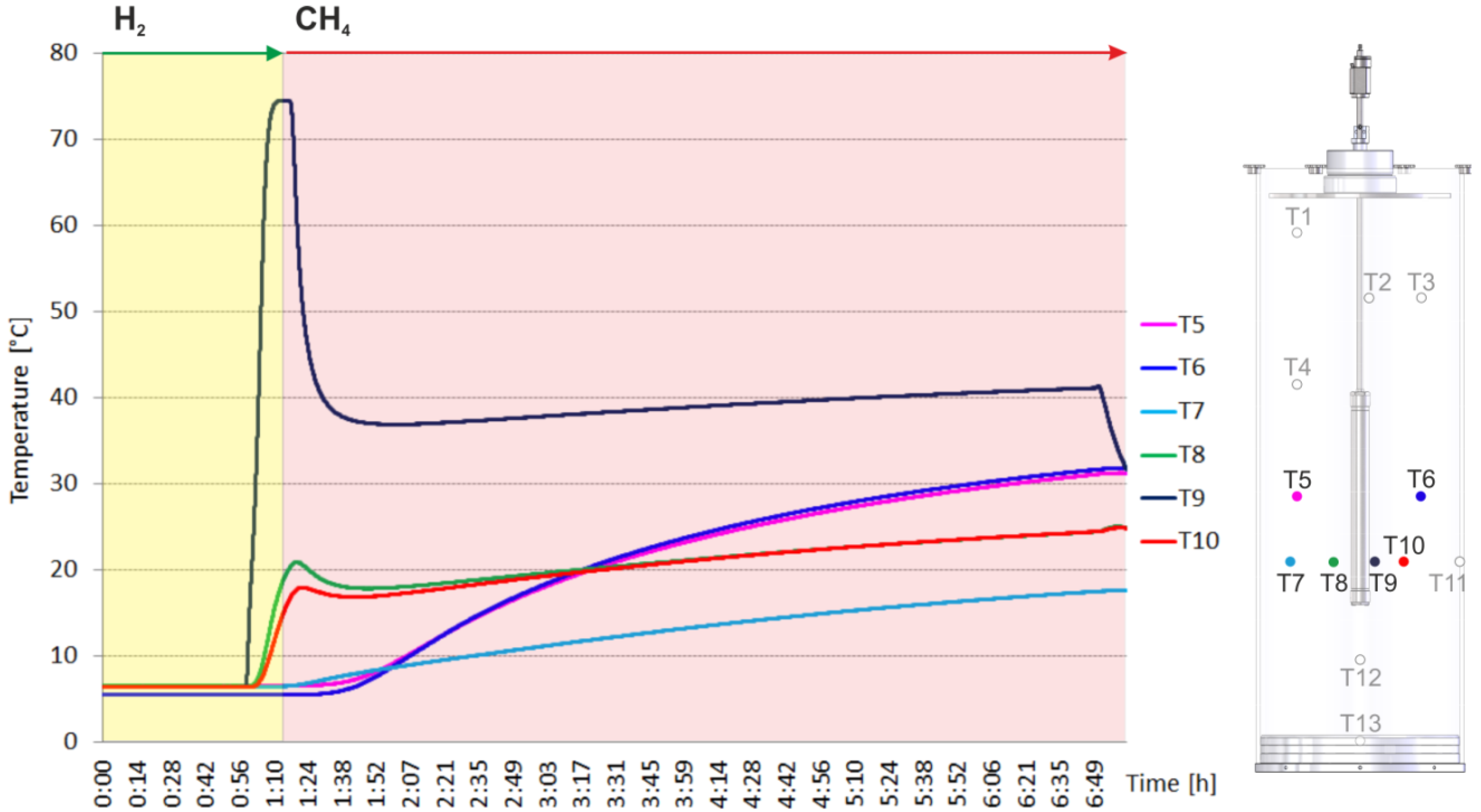
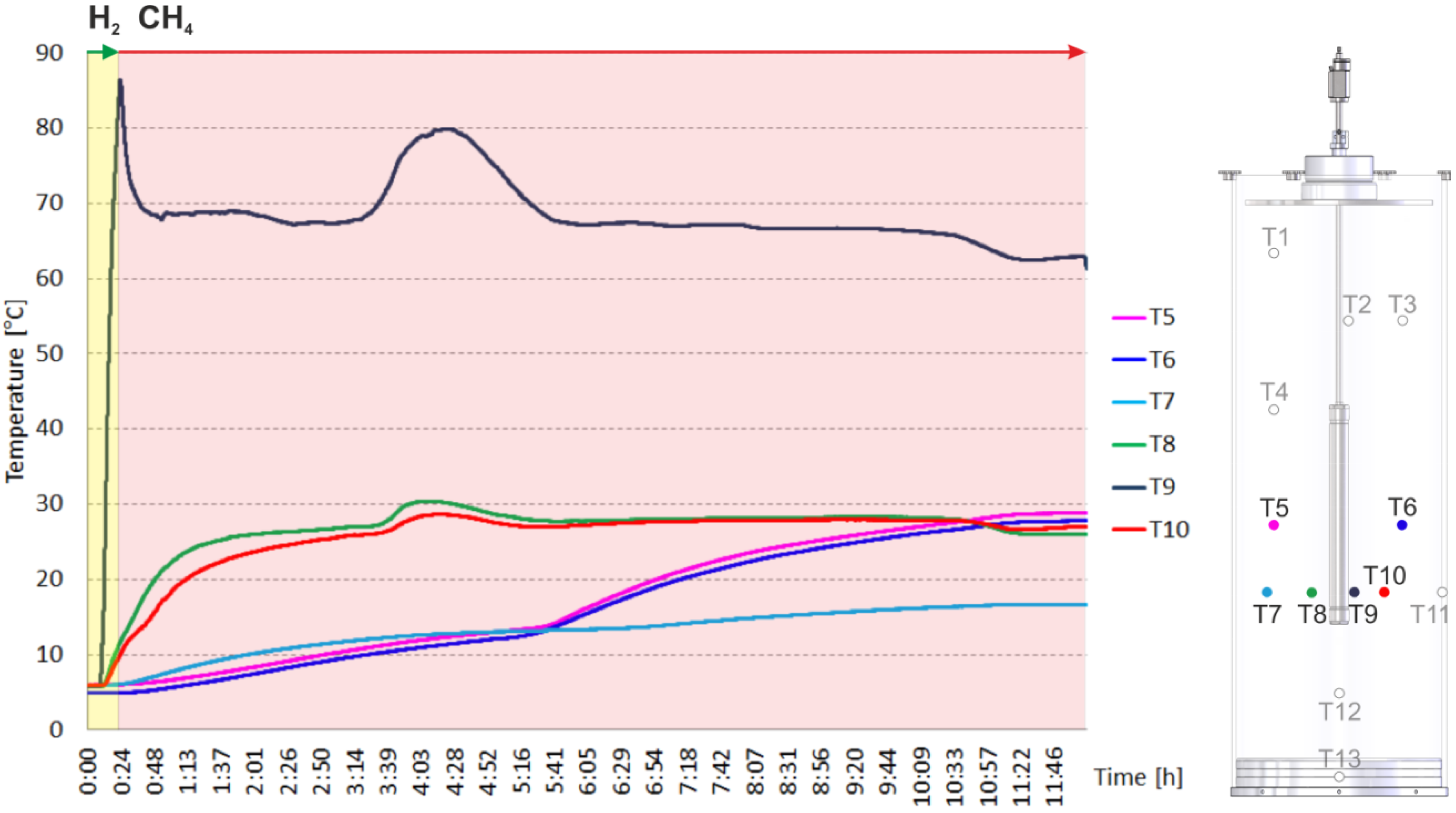
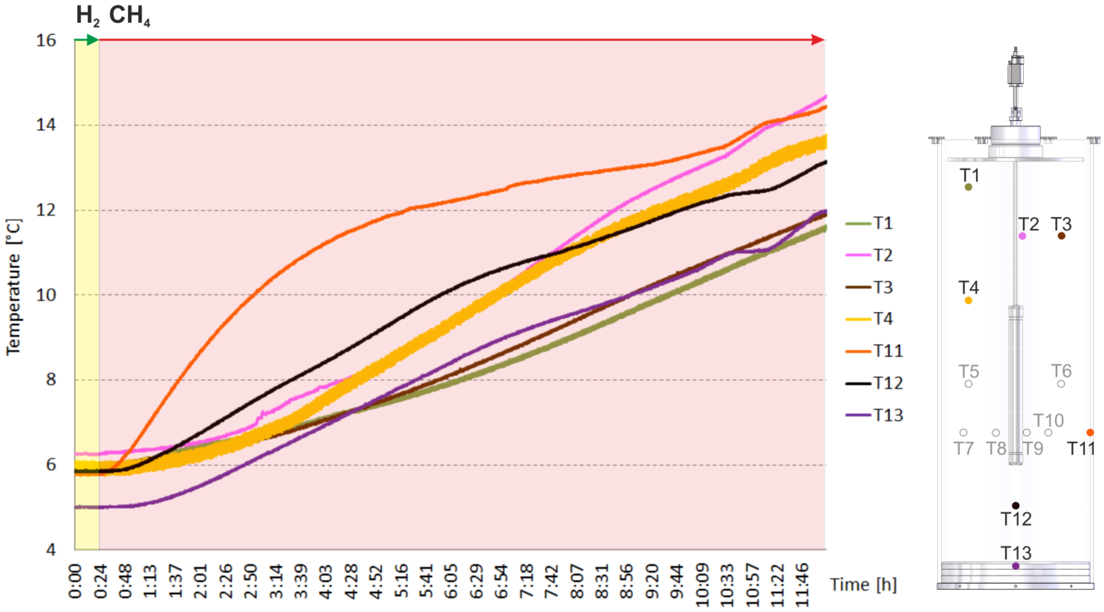
2.2. Heating and Production Test


3. Experimental
3.1. The Counter-Current Heat-Exchange Reactor
- The cold educts CH4 and air flowed separately through a ceramic pipe with two parallel channels. Since the volume of the supplied air is about ten times larger compared to the volume of the supplied CH4, the volumetric flow of both gases in front of the catalyst bed was unbalanced and the mixing of the educts uncompleted. This led to varying combustion of CH4 within the catalyst bed and thus to a spatial unsymmetrically release of heat.
- A ceramic inlay was supposed to protect the outer shell of the reactor which consisted of a Ni-based alloy (ThyssenKrupp VDM) from the heat generated at the catalyst. Unfortunately this ceramic inlay also impaired the heat transfer from the hot product gases to the environment via the reactor wall significantly.
- In general, the heat transfer from the reactor to the environment was poor.
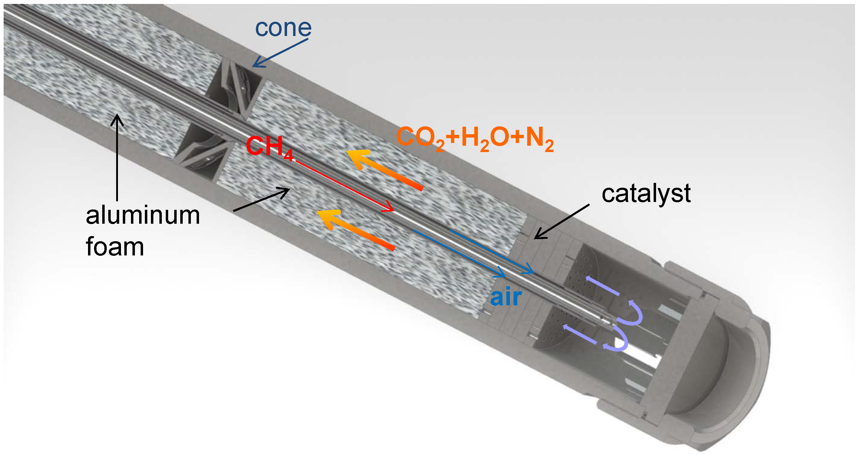
- The cold educts CH4 and air are fed separately through an inner and outer tube made of stainless steel into the reactor. Both tubes end in a nozzle which permits a complete mixing of the educts before entering the catalyst bed.
- The ceramic inlay was removed since the temperatures at the catalyst bed can be controlled by the volume flow of the educts.
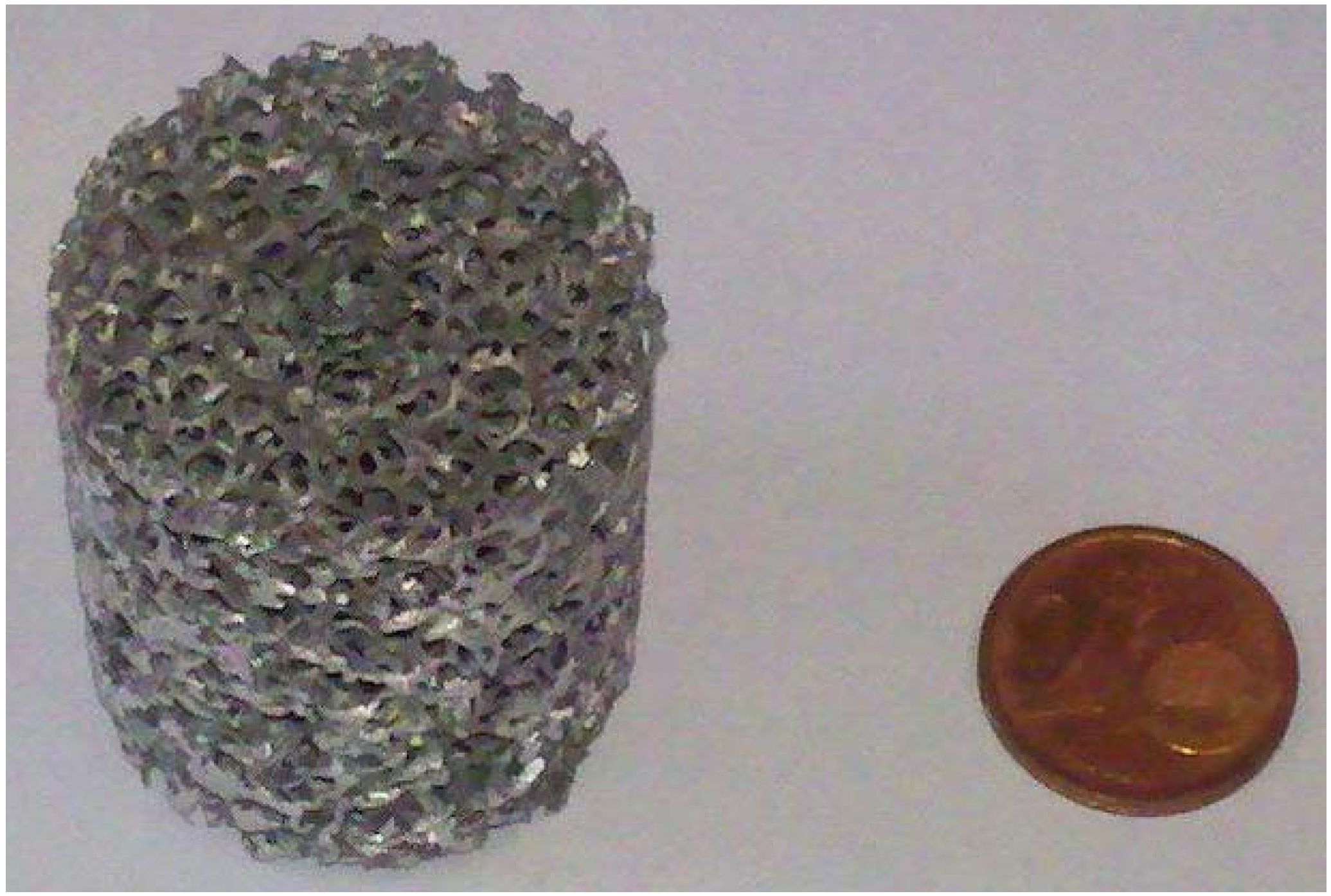
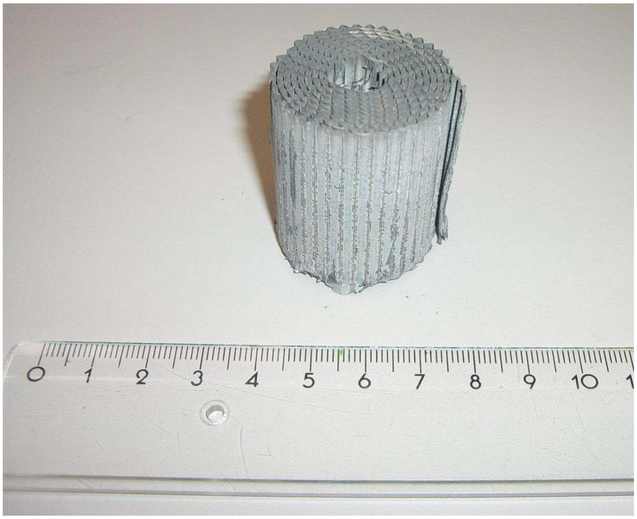
- The heat transfer was improved by the embedment of aluminum foam between the inner feed gas tubes and the outer shell.

3.2. The Catalysts

| Catalytic active material | Metal salt | Purity | Manufacturer |
|---|---|---|---|
| Palladium | Pd(NO3)2 x H2O | 99.9% | Alfa Aesar GmbH & Co KG |
| Iridium | IrCl3 | 99.9% | Alfa Aesar GmbH & Co KG |
| Platinum | H2PtCl6 6 H2O | 99.95% | Alfa Aesar GmbH & Co KG |


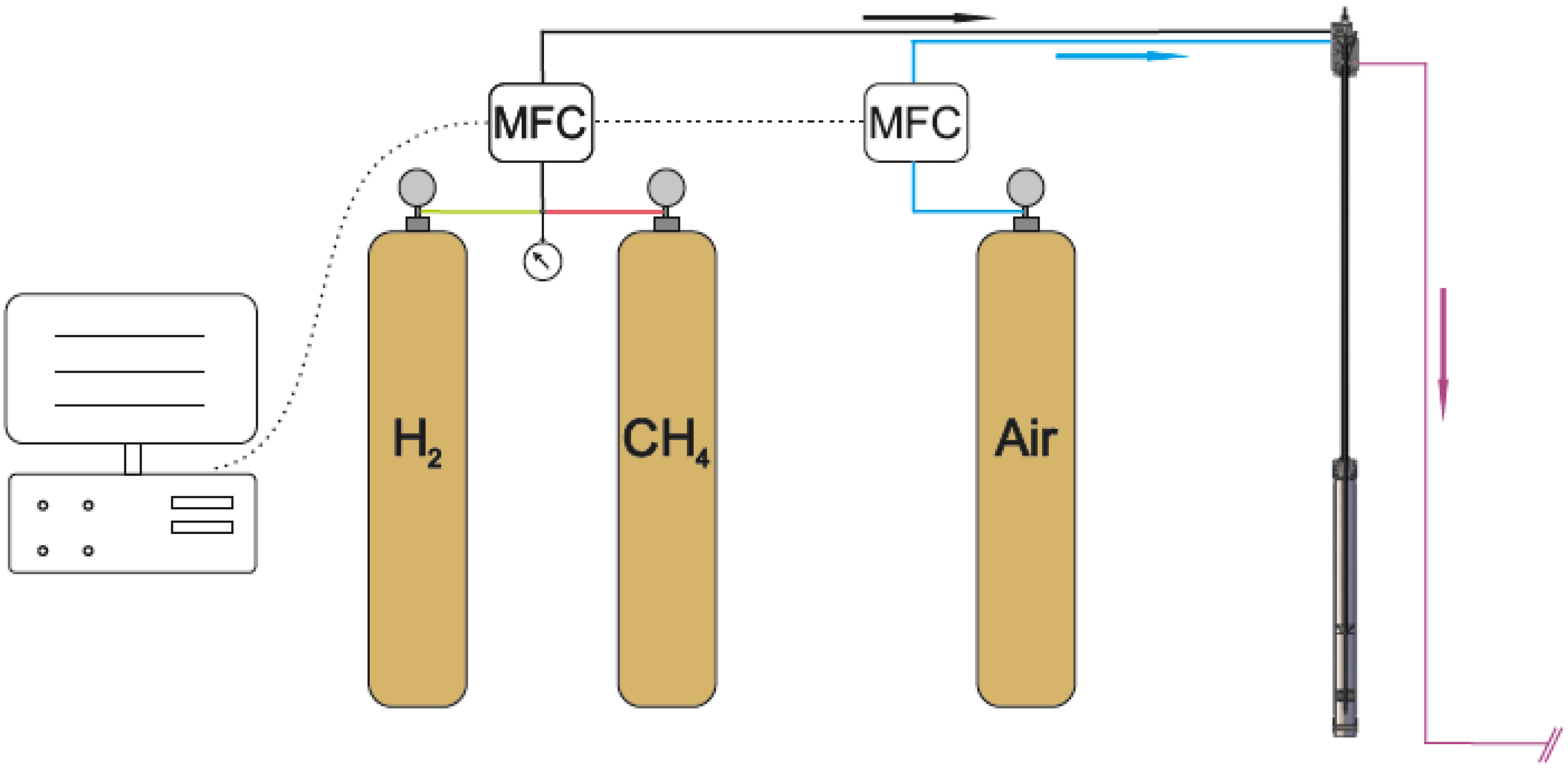
3.3. The Gas Supply
4. Conclusions
Acknowledgements
Conflicts of Interest
References
- Cranganu, C. In-situ thermal stimulation of gas hydrates. J. Pet. Sci. Technol. 2009, 65, 76–80. [Google Scholar]
- Schicks, J.M.; Spangenberg, E.; Giese, R.; Steinhauer, B.; Klump, J.; Luzi, M. New approaches for the production of hydrocarbons from hydrate bearing sediments. Energies 2011, 4, 151–172. [Google Scholar] [CrossRef]
- Sloan, E.D.; Koh, C.A. Clathrate Hydrates of Natural Gases, 3rd ed.; CRC Press Taylor and Francis Group: Boca Raton, FL, USA, 2008. [Google Scholar]
- Kvenvolden, K.A.; Lorenson, T.D. The Global Occurrence of Natural Gas Hydrates. In Natural Gas Hydrates—Occurrences, Distribution, and Detection; Paull, C.K., Dillon, W.P., Eds.; American Geophysical Union: Washington, DC, USA, 2001; pp. 3–18. [Google Scholar]
- Yasuda, M.; Dallimore, S. Summary of the methane hydrate second mallik production test. J. Jpn. Assoc. Pet. Technol. 2007, 72, 603–607. [Google Scholar] [CrossRef]
- Yang, X.; Gates, I.D. Design of hybrid steam—In situ combustion bitumen recovery processes. Nat. Resour. Res. 2009, 18, 213–233. [Google Scholar] [CrossRef]
- Air Liquide. Downloadable Material Safety Data Sheet (MSDS) for CH4; Air Liquide: Paris, France, 1966. [Google Scholar]
- Rydzy, M.B.; Schicks, J.M.; Naumann, R.; Erzinger, J. Dissociation enthalpies of synthesized multicomponent gas hydrates with respect to the guest composition and cage occupancy. J. Phys. Chem. B 2007, 111, 9539–9545. [Google Scholar] [CrossRef] [PubMed]
- Chaouki, J.; Sapundzhiev, G.C.; Kusohorsky, D.; Klvana, D. Combustion of methane in a cyclic catalytic reactor. Ind. Eng. Chem. Res. 1994, 33, 2957–2963. [Google Scholar] [CrossRef]
- Ohtsuka, H. The oxidation of methane at low temperatures over zirconia-supported Pd, Ir and Pt catalysts and deactivation by sulfur poisoning. Catal. Lett. 2011, 141, 413–419. [Google Scholar] [CrossRef]
- Jang, J.; Santamarina, J.C. Recoverable gas from hydrate‐bearing sediments: Pore network model simulation and macroscale analyses. J. Geophys. Res. 2011, 116, B08202. [Google Scholar]
- Lyubovsky, M.; Pfefferle, L. Methane combustion over the α-alumina supported Pd catalyst: Activity of the mixed Pd/PdO state. Appl. Cat. A 1998, 173, 107–119. [Google Scholar] [CrossRef]
© 2013 by the authors; licensee MDPI, Basel, Switzerland. This article is an open access article distributed under the terms and conditions of the Creative Commons Attribution license (http://creativecommons.org/licenses/by/3.0/).
Share and Cite
Schicks, J.M.; Spangenberg, E.; Giese, R.; Luzi-Helbing, M.; Priegnitz, M.; Beeskow-Strauch, B. A Counter-Current Heat-Exchange Reactor for the Thermal Stimulation of Hydrate-Bearing Sediments. Energies 2013, 6, 3002-3016. https://doi.org/10.3390/en6063002
Schicks JM, Spangenberg E, Giese R, Luzi-Helbing M, Priegnitz M, Beeskow-Strauch B. A Counter-Current Heat-Exchange Reactor for the Thermal Stimulation of Hydrate-Bearing Sediments. Energies. 2013; 6(6):3002-3016. https://doi.org/10.3390/en6063002
Chicago/Turabian StyleSchicks, Judith M., Erik Spangenberg, Ronny Giese, Manja Luzi-Helbing, Mike Priegnitz, and Bettina Beeskow-Strauch. 2013. "A Counter-Current Heat-Exchange Reactor for the Thermal Stimulation of Hydrate-Bearing Sediments" Energies 6, no. 6: 3002-3016. https://doi.org/10.3390/en6063002