Review

Recent Approaches to Controlling the Nanoscale Morphology of Polymer-Based Bulk-Heterojunction Solar Cells

by
Wasiu Adebayo Hammed
,
Rosiyah Yahya
,
Abdulra'uf Lukman Bola
and
Habibun Nabi Muhammad Ekramul Mahmud
*
Department of Chemistry, Faculty of Science, University of Malaya, Kuala Lumpur 50603, Malaysia
*
Author to whom correspondence should be addressed.
Energies 2013, 6(11), 5847-5868; https://doi.org/10.3390/en6115847
Submission received: 4 July 2013 / Revised: 28 August 2013 / Accepted: 6 September 2013 / Published: 8 November 2013

Abstract

:
The need for clean, inexpensive and renewable energy has increasingly turned research attention towards polymer photovoltaic cells. However, the performance efficiency of these devices is still low in comparison with silicon-based devices. The recent introduction of new materials and processing techniques has resulted in a remarkable increase in power-conversion efficiency, with a value above 10%. Controlling the interpenetrating network morphology is a key factor in obtaining devices with improved performance. This review focuses on the influence of controlled nanoscale morphology on the overall performance of bulk-heterojunction (BHJ) photovoltaic cells. Strategies such as the use of solvents, solvent annealing, polymer nanowires (NWs), and donor–acceptor (D–A) blend ratios employed to control the active-layer morphologies are all discussed.

1. Introduction

The rapid growth in the human population is having an increasing impact on global energy consumption [1]. The search for alternative sources of energy is continuing, as reserves of fossil fuels, the current predominant source of energy, are dwindling and their damaging effects are increasing by the day. Although there are other means of generating clean and renewable energy such as wind, geothermal and bio-energy, solar energy seems to be the most abundant [2]. Photovoltaic cells or solar cells directly convert sunlight into electricity via the absorption of photons [3,4,5]. Silicon-based solar cells and other inorganic types of photovoltaic cells that currently dominate [6] the solar-cell market because of their higher power-conversion efficiency (PCE) are expensive. For example, the cost of production of the photon absorber in silicon-based solar cells is almost half of the total cost [7,8,9]. The viability of organic solar cells as an emerging alternative to conventional solar cells is increasing as a result of their fast and cost-effective production processes [10]. Alongside other challenges, improving the PCE is a significant one in the fabrication of organic photovoltaic devices (OPVs) [11,12,13]. Currently, a PCE value of 9.2% has been achieved by one of the leading technological companies in this field, Mitsubishi Chemical [14]. For solution processed tandem solar cells, You et al. [15] recently reported the first certified PCE over 10%. The expectation of researchers in this field is that PCE values of 10% will soon be achieved and will perhaps reach as high as 15% in tandem structures. The overall efficiency of OPVs depends predominantly on the active-layer morphology [16,17,18], which consists of photon-trapping donor and acceptor materials that lead to the formation of excitons. The successful separation of excitons into holes and electrons, and their subsequent transfer to the corresponding electrodes, results in the power conversion from solar energy into electrical energy.
Understanding the roles of controlled nanoscale morphology in the optimal performance of photovoltaic cells is the subject of this brief review. The first section presents the basic operational principles of OPVs, with a brief look at device fabrication. In the subsequent section we explore the concept of bulk-heterojunctions (BHJs) to reveal the essence of the nanoscale morphology of donor–acceptor (D–A) materials. Finally, some of the current methods employed to control, as well as to improve, the morphology of the active layer are mentioned in detail.

2. Operational Principles of OPVs

The basic overall design of OPVs features two polar terminals (Figure 1): the negative electrode (cathode), which is usually made of metals with low work function such as aluminium and the positive electrode (anode) which is typically made from transparent indium-doped tin oxide (ITO). The situation is, of course, reversed for the “inverted” device architecture. The transparent ITO electrode, which is situated on top of a transparent substrate (flexible polymer or glass), allows the passage of photons from the sun. These photons are in turn absorbed by the photoactive-layer (Figure 1) materials (the D–A materials), thus inducing photoexcitation.
Figure 1. (a) Typical bulk-heterojunction (BHJ) device structure; and (b) illustration of BHJ active layer.
Energies 06 05847 g001
Photoexcitation results in a noticeable polarization of the chromophoric group of the conjugated molecule, which stimulates the formation of a bound electron–hole pair quasiparticle called an exciton [19]. The excitons that are generated diffuse through a D–A phase where they recombine with emission of energy or reach a D–A interface. At the interface, excitons dissociate into free charge carriers as a result of electron flow from the lowest unoccupied molecular orbital (LUMO) of the conjugated polymer (donor) to the LUMO of the acceptor. Each charge carrier is transported through the device to the appropriate electrode by a drift built by internal electric fields, thus creating electricity [20]. The exciton diffusion length is the distance travelled by the exciton before it undergoes recombination in the organic semiconductors, and it is around 10–20 nm [21]. In order to avoid exciton recombination, a factor which leads to a decrease in the PCE [22,23], the distance between the interface and the region of exciton generation must be of the same magnitude (10–20 nm), as the excitons generated within this interval are most likely to dissociate into free electrons and holes [24]. This highlights the importance of a carefully controlled active layer for the purpose of achieving high PCE values. In order to maximize charge generation, a large interface together with continuous active-layer morphology is needed to ensure a hitch-free flowing of charge carriers to the collecting electrodes [25]. The current travelling through an illuminated solar cell when there is no external resistance (i.e., when the electrodes are connected together) is the short-circuit current, Jsc. Within the organic semiconductors, the short circuit current is determined by the product of the photoinduced charge carrier density and the charge carrier mobility. The voltage delivered by a solar cell when the electrodes are isolated (infinite load resistance) is called the open-circuit voltage, Voc. For bulk heterojunction solar cells, Voc is linearly dependent on the energy difference between the highest occupied molecular orbital (HOMO) level of the electron donors and the LUMO level of the electron acceptors [26]. Assuming that the solar cell is operating at its maximum current (Jmax) and voltage (Vmax), the power generated by the solar cell is the product of Jmax and Vmax. Denoted as maximum power output (MPO), it is the point where the power output is largest. To determine the efficiency of a solar cell, this power needs to be compared with the incident light intensity. The fill factor (FF) is the ratio between the maximum power output (Pmpo = Jmax Vmax) of the cell and the maximum theoretical power output (Jsc Voc). It measures how square the solar cell is:
F F = J m a x V m a x J s c V o c
In the current–voltage (J–V) plot of a solar cell (Figure 2), the intersection of the abscissa and ordinate describes the Voc and the Jsc, respectively. The PCE is the measure of maximum power (Pmpo) generated by the solar cell relative to the power in the incident photon (Pin):
PCE = P mpo P i n = J max V max F F P i n
where Pin is the incident light is usually fixed at 100 mW/cm2 under an air mass (AM) of 1.5 G.
For organic solar cells, the ratio of number of extracted charge carriers to the number of absorbed photons in the active layer is its external quantum efficiency (EQE) or incident photon to converted electron (IPCE) value [27,28]:
EQE = J s c P i n   λ h c e
where h, c, and e are Planck’s constant, the velocity of light and the elementary charge, respectively. EQE is the product of all the efficiencies in the energy-transfer processes [29]:
EQE = η a b s η d i f f η t c η t r η c c
where ηabs is the photon-absorption efficiency (number of excitons generated per number of incident photons); ηdiff is the diffusion efficiency of the charge carrier (number of excitons diffusing to the D–A interface per number of excitons generated); ηtc is the efficiency of the charge-carrier separation (number of dissociated excitons per number of excitons at the interface); ηtr is the charge-transport efficiency; and ηcc is the charge-collection efficiency [30]. The product of the last four parameters (ηdiffηtcηtrηcc) defines the internal quantum efficiency (IQE). Thus:
EQE = η a b s IQE
where IQE is a key factor that determines the quality of photovoltaic cells as it provides a qualitative assessment of its ability to separate excitons into free charges and collect them at the electrodes.
Examining Equation (2), it is apparent that maximizing the performance of the photovoltaic cells depends on maximizing the values of Voc, Jsc and FF. Fabrication procedures such as morphology control and post deposition treatments which include thermal and solvent annealing are the important methods for optimizing Voc, Jsc and FF.
Figure 2. J–V curve for photovoltaic cells with and without illumination.
Energies 06 05847 g002

3. BHJ Solar Cells

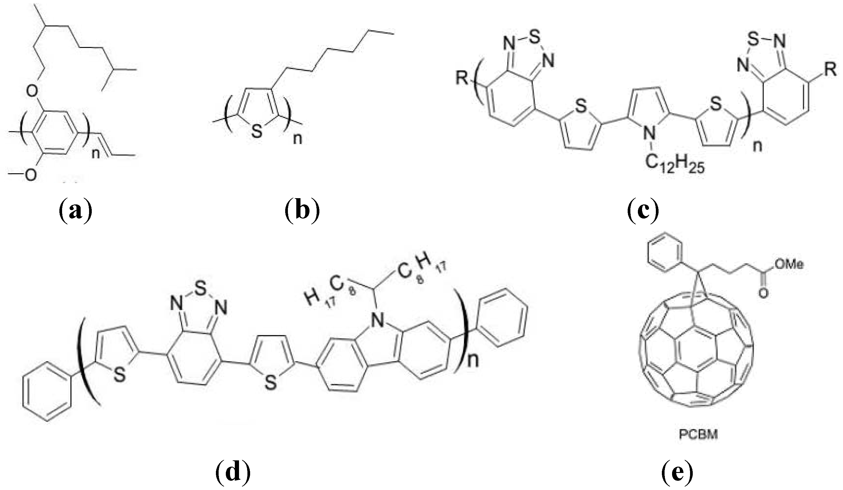
Much effort has been directed towards manipulating the active layer of organic solar cells in order to improve the exciton harvest. As described earlier, exciton dissociation occurs at a short distance from the interface. However, in bilayer heterojunction, exciton diffusion length is within a very thin region around the limited interfacial area which is not enough to absorb most of the solar radiation flux thereby limiting the exciton dissociation efficiency. For this reason, a large interface between the donor and acceptor phase with a continuous morphology is essential. This is the basis of the BHJ concept (Figure 1), where the active layer consists of an interpenetrating network of donor and acceptor materials so that all the excitons are produced close to a heterojunction and thus generating polaron pairs anywhere in the film [31]. As a result, low-cost and efficient devices can be fabricated because of the bicontinuous morphology of the BHJ [32,33,34]. The intermixing distance of the two materials (donor and acceptor) should be less than the exciton-diffusion length. At the same time, the film morphology has to allow unrestricted movement of the charge carriers to their respective contacts for extraction [35,36]. In a typical BHJ device architecture (Figure 1b), a nanoscale bi-continuous network is obtained by mixing an electron donor and an electron acceptor in a common solvent and then spin-casting it while the solvent evaporates [37,38]. π-conjugated polymers, such as poly[2-methoxy-5-(3′-7′-dimethyloctyloxy)-1,4-phenylenevinylene] (MDMO-PPV) [39], poly(3-hexylthiophene) (P3HT), poly[N-dodecyl-2,5-bis(2′-thienyl)pyrrole-2,1,3-benzothiadiazole] (PTPTB) and poly[N-11′′-henicosanyl-2,7-carbazole-alt-5,5-(4′,7′-di-2-thienyl-2′,1′,3′-benzothiadiazole)] (PCDTBT) [40,41], have been extensively studied and are used as donor materials (Figure 3). Phenyl-C61-butyric acid methyl ester (PCBM) is the most common acceptor [42,43,44], not just because of the ease with which it forms a segregated phase with organic donors, but also because of its good electron affinity [22]. Other materials such as small organic molecules [45], inorganic semiconductor quantum dots [46,47,48,49], and solution-processable functionalized graphene [50,51,52,53,54] have successfully been used as BHJ active layers.
Figure 3. Some of the commonly used donor and acceptor materials in organic photovoltaic devices (OPVs). Donors: (a) poly[2-methoxy-5-(3′-7′-dimethyloctyloxy)-1,4-phenylenevinylene] (MDMO-PPV); (b) poly(3-hexylthiophene) (P3HT); (c) poly[N-dodecyl-2,5-bis(2′-thienyl)pyrrole-2,1,3-benzothiadiazole] (PTPTB); and (d) poly[N-11′′-henicosanyl-2,7-carbazole-alt-5,5-(4′,7′-di-2-thienyl-2′,1′,3′-benzothiadiazole)] (PCDTBT). Acceptor: (e) phenyl-C61-butyric acid methyl ester (PCBM).
Energies 06 05847 g003

4. Morphology of BHJs

It is necessary to comprehend the importance of manipulating the morphology, as the performance of BHJ solar cells depends largely on the nanoscale morphology of the photoactive layer. Controlling the interpenetrating network morphology, and optimizing the charge-transport mobility and solar absorption of the polymer are essential for achieving devices with improved performances. With regard to the solar absorption and charge mobility, the introduction of molecular band gap engineering has yielded notable successes [55,56,57] in the synthesis of new low band gap polymers (donors) with balanced charge-carrier transport in relation to PCBM (acceptor). However, difficulties in characterizing and optimizing organic film morphology make it difficult to understand and control the morphology [58]. With little or no application of post-deposition treatments, it is difficult to obtain an environmentally stable and perfect morphology of which the composite film forming the active layer is naturally assembled to a required level of phase separation. Therefore, processing conditions such as solvent effect [59], the blend ratio of the constituents [60,61,62], as well as post-deposition treatments, have to be considered. In the following sections, we highlight the recent methods for controlling the formation of the phase-separated morphology of BHJ solar cells.

5. Strategies for Controlling the Active-Layer Morphology in BHJs

Protocols for controlling the formation of morphology with self-organized ordered structures of the polymer units within the active layer can be realized by appropriate solvent selection [63], slow drying of spin-coated films [64,65,66], thermal [67,68,69] and solvent annealing [70,71,72] treatment of the films, surface treatment of ITO [73], the application of an electric field [74], the use of chemical additives [75], additive-spraying techniques [76], and the use of nanowires (NWs) [77] and nanoparticles [78].

5.1. Roles of Solvent in Controlling the Active-Layer Morphologies
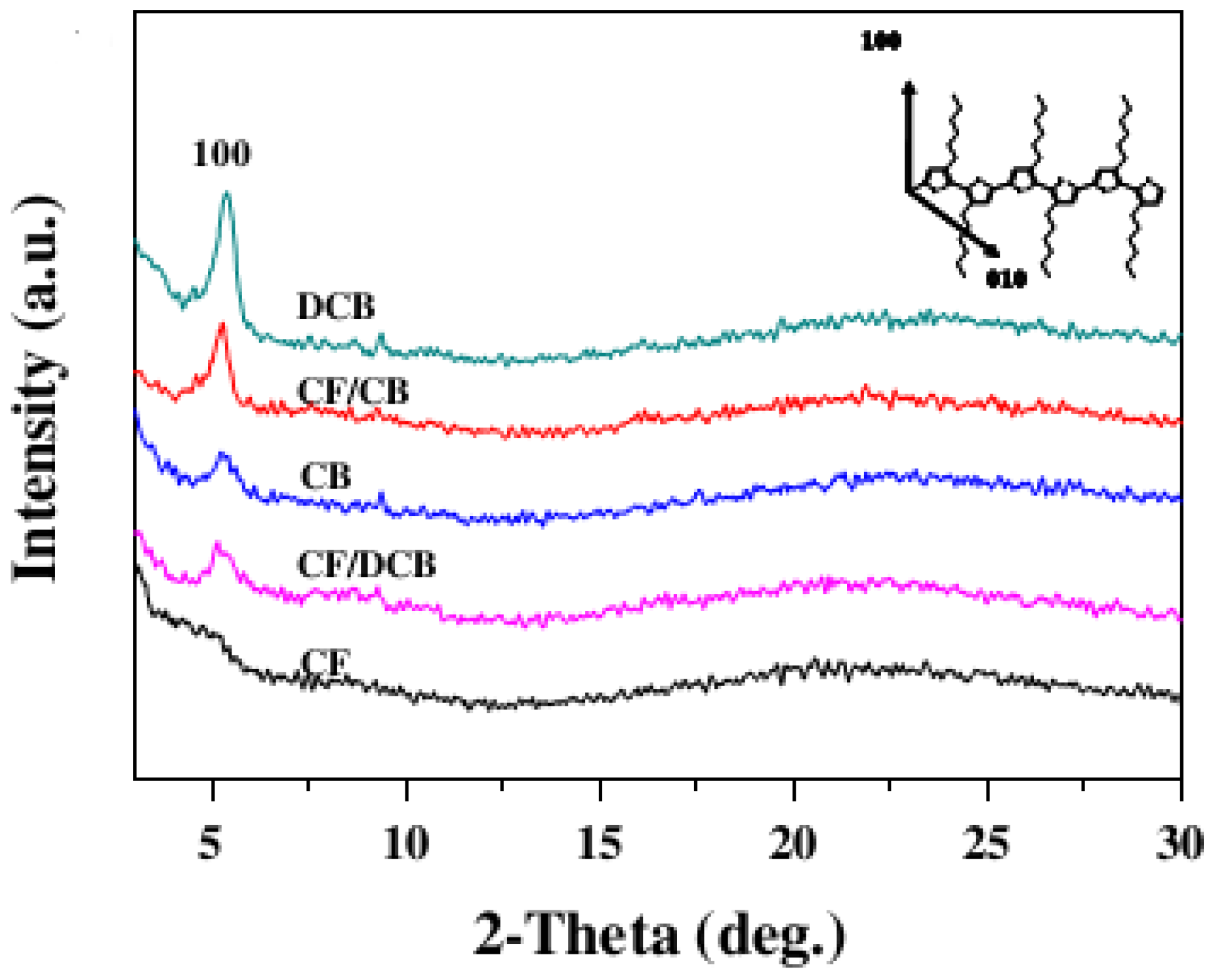
The dynamic crystalline order of the polymer during casting has been found to be dependent upon the variation in the evaporation time of the spin-coating solvents. As a result, properties of charge-carrier mobility and subsequent performance of the polymer heterojunction solar cell were altered. The vapour pressure of each solvent determines its drying time. The degree of phase segregation is also strongly influenced by the blend’s miscibility with these casting solvents [79,80]. The use of high-boiling solvent improves both the morphology and the corresponding solar-cell performance because the slow evaporation rate of the solvent during the active-layer deposition allows for a prolonged crystallization time. A P3HT:PCBM film prepared using dichlorobenzene (DCB) [boiling point (bp) = 178 °C] or chlorobenzene (CB) (bp = 132 °C) possesses a better-ordered structure and an improved crystallinity in comparison with a film prepared using the low-boiling solvent, chloroform (CF) (bp = 61 °C), as is shown (Figure 4) by their X-ray diffraction (XRD) intensities [81].
Figure 4. High-boiling solvent, dichlorobenzene (DCB), displayed increased intensity at 2θ ≈ 5.2. Reprinted with permission from Elsevier [81].
Energies 06 05847 g004
Recently, Verploegen et al. [70] studied the differences between the spin-cast films produced with CF or CB as solvents using grazing incidence wide-angle X-ray scattering (GIWAXS) of the film (Figure 5). They observed that the direction of the P3HT lamellae for the film cast using CB was different from the direction of the P3HT lamellae for the film cast using CF. Whereas perpendicular lamellae were recorded for the P3HT cast using CB, parallel lamellae were observed in the case of the film cast using CF. This observation was attributed to the existence of strong in-plane π–π scattering in the former that was absent in the latter. Therefore, a better arrangement of the P3HT component was observed in the film cast using CB, a higher-boiling solvent, than in the film cast using CF.
Figure 5. Grazing incidence wide-angle X-ray scattering (GIWAXS) images of a 1:1 P3HT:PCBM blend cast using chloroform (CF) and chlorobenzene (CB), respectively. Reprinted with permission from ACS [70].
Energies 06 05847 g005
In the case of mixed solvents, P3HT has a competitive film growth rate when spin-cast using solvents with two different vapour pressures and solubilities, yielding an active layer with improved crystallinity and devices with enhanced performance. As a result, the device fabricated from mixed solvent as CF/CB showed a better PCE value of 3.7% in comparison with those fabricated from CF and CB mono solvents [81]. Using inverted polymer solar cell based on P3HT:ICBA, Lin et al. [82] demonstrated that a mixture of DCB and CB may result in different phase separations because of differences in their boiling points. The active-layer drying time was controlled with a higher ratio of DCB to CB (0.8/0.2 mL), while horizontal phase separation was reduced by the addition of the conductive polymer polyvinyl carbazole (PVK) [82]. Therefore, the Voc of the device increased dramatically from 0.66 V to 0.82 V, leading to an increase in PCE from 2.6% to 4.3%. When the same co-solvent (DCB/CB) was used by Jang et al. [83] to prepare P3HT:PCBM film, the following results were obtained: Jsc = 10.4 mA/cm2, Voc = 606 mV, FF = 45.5%, and the PCE was calculated to be 2.9%.

5.2. Use of Chemical Additives

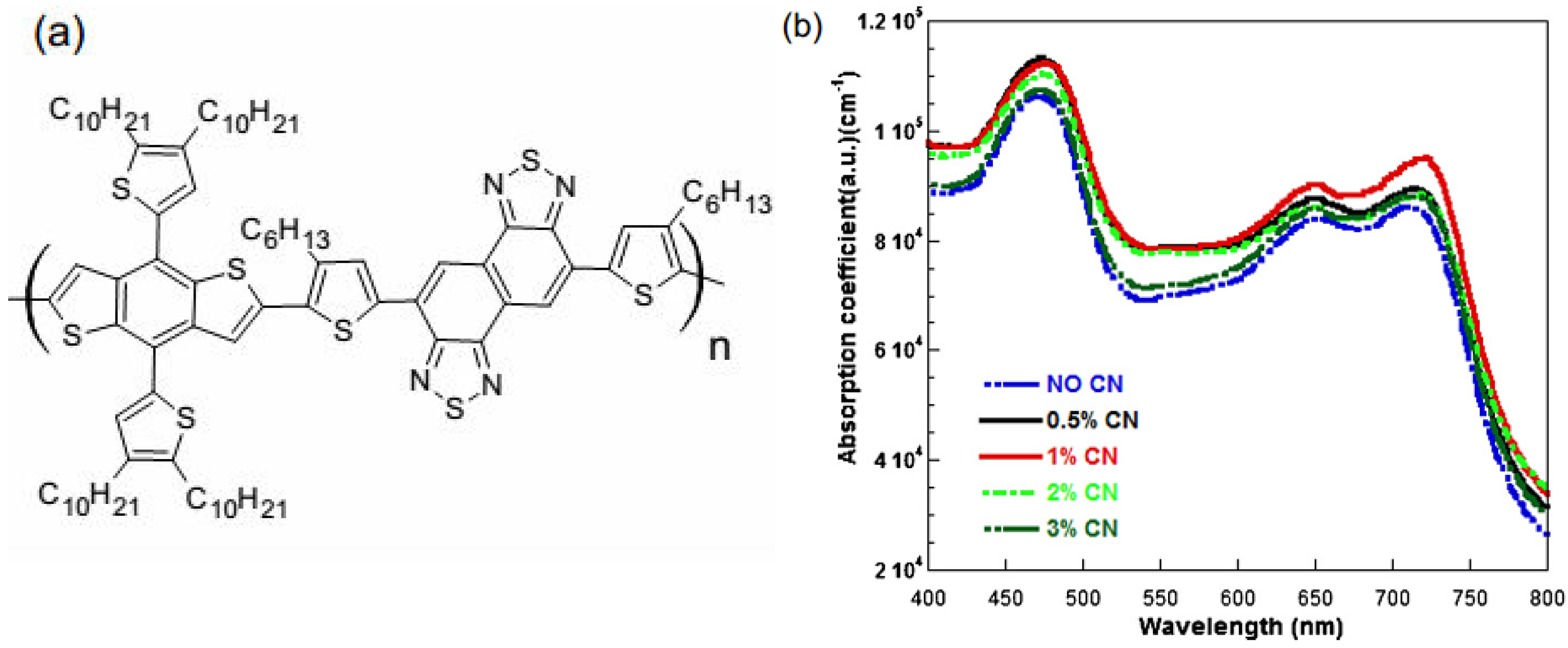
A new approach to optimizing the morphology of the BHJ active-layer blended film is to introduce a chemical additive to the D–A solution. An effective additive must be able to interact extensively with the active-layer components during thin film formation. Therefore, the boiling point of the additive must be higher than that of the casting solvents. Also, additive should selectively dissolve the donor and acceptor components. The mechanism of interaction between diiodooctane (DIO), a processing additive, and a thieno[3,4-b]thiophene/benzodithiophene:[6,6]-phenyl-C71-butyric acid methyl ester (PTB7:PC71BM) aggregate in CB was investigated using X-ray scattering techniques [75]. A small-angle X-ray scattering (SAXS) image of the PTB7:PC71BM solution exhibited a densely aggregated species, which became significantly reduced upon the addition of a standard concentration of 3% v/v DIO. The results showed that the addition of a DIO additive to the CB solution selectively dissolved PC71BM aggregates and facilitated the intercalation of PC71BM into PTB7 domains, thereby leading to the formation of smaller domains and enhanced D–A interpenetration within the film. The enhanced D–A interpenetration was alluded to the strong interaction between the partial negative charge of the iodine atom and the electron deficient PC71BM. The addition of a small amount of 1-chloronaphthalene (CN) as the solvent additive into o-dichlorobenzene (o-DCB) could improve the absorption coefficient, reduce the internal series resistance, enhance charge carrier transport, and therefore improve the performance of devices with 4,8-bis(4,5-didecyl-2-thienyl)-benzo[1,2-b:4,5-b′]dithiophene-alt-[4,9-bis(4-hexyl-2-thienyl)-naphtho[1,2-c:5,6-c′]bis[1,2,5]thiadiazole-5,5-diyl] (PBDT-DTNT) as the electron donor and PC71BM as the electron acceptor because CN has considerable impact on the aggregation and packing of the PBDT-DTNT molecular conformations [84] (Figure 6).
Figure 6. (a) Chemical structure of 4,8-bis(4,5-didecyl-2-thienyl)-benzo[1,2-b:4,5-b′]dithiophene-alt-[4,9-bis(4-hexyl-2-thienyl)-naphtho[1,2-c:5,6-c′]bis[1,2,5]thiadiazole-5,5-diyl] (PBDT-DTNT); and (b) the absorption coefficients of the PBDT-DTNT:PC71BM [(6,6)-phenyl-C71-butyricacid methyl ester] films produced using o-dichlorobenzene (o-DCB) solutions with different concentrations of 1-chloronaphthalene (CN) solvent additives and without CN. Reprinted with permission from Elsevier [84].
Energies 06 05847 g006
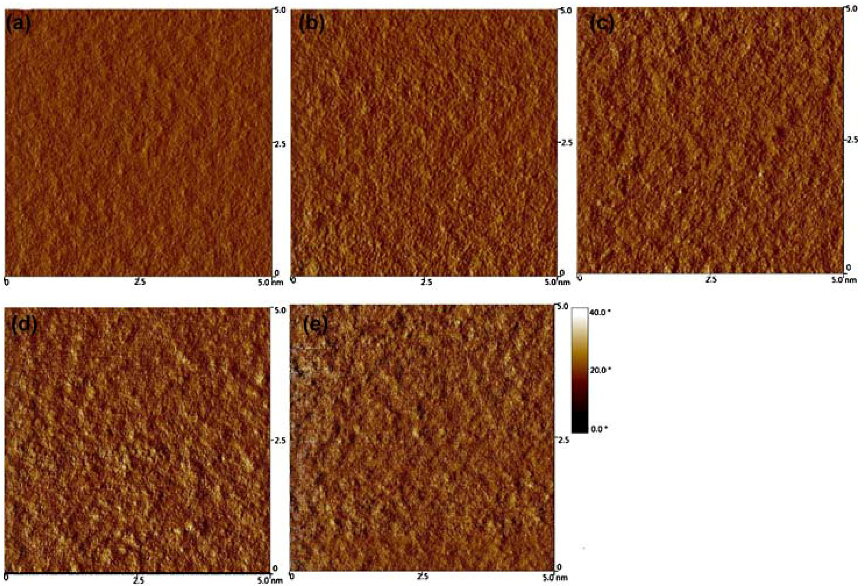
The observed atomic force microscopy (AFM) image of the film prepared from an o-DCB solution with a CN additive indicated an increased aggregate cluster with increasing CN concentrations, and the highest root-mean-square (RMS) roughness of 3.90 nm was obtained with a 3% CN concentration (Figure 7). The PCE of a photovoltaic cell produced in this manner was better than that of the device manufactured without a CN additive [84]. A previous result by Moon et al. [85] showed a different role played by the CN additive on the morphology of a thin film consisting of (4,4-didodecyldithieno[3,2-b:20,30-d]silole)-2,6-diyl-alt-(2,1,3-benzothiadiazole)-4,7-diyl (Si-PDTBT) donor and [6,6]-phenyl-C70-butyric acid methyl ester (PC70BM) acceptor. The additive suppressed the large-scale aggregation of PC70BM and promoted the correct morphology for high-performance BHJ devices [85]. The nanomorphology of the Si-PDTBT:PC70BM BHJ material without the use of a CN additive was indicative of oval-shaped PC70BM aggregate with a diameter >200 nm [85]. The P3HT:[6,6]-phenyl-C61 butyric acid methyl ester (PC61BM) film produced using 1,6-hexanedithiol (HDT) or 1,8-octanedithiol (ODT) as solvent additives possessed optimal phase segregation with a suitable domain size [86]. The better performance of the HDT- and ODT-incorporated film was attributed to the influence of the boiling point and the solubility parameters of the additives in allowing a thorough interaction between the additive and fullerene, as was depicted by data obtained from grazing-incidence X-ray diffractometry (GIXRD) and scanning transmission X-ray microscopy (STXM) [86]. Keawprajak et al. [87] studied the effect of crystallizable solvent on the morphology and performance of P3HT:PCMB solar cells produced using CB with varying amounts of 1,3,5-trichlorobenzene (TCB) as the crystallizable aromatic solvent. The authors showed that the decelerated release of the residual solvent during the solidification of the blend film improves the self-organization of the P3HT, allowing the surface of the film to become smoother with the addition of TCB and thereby improving the organic-matter-cathode contact. The authors concluded that the polymer-blend film formed using a TCB crystallizable solvent displayed better crystallinity, optical absorption and polymer morphology than the film formed without using the TCB crystallizable solvent. The PCE of solar cells fabricated in this manner was higher than that of cells formed without the use of a TCB solvent [87].
Figure 7. Atomic force microscopy (AFM) images obtained for PBDT-DTNT:PCBM films spin-cast from: (a) o-DCB solution; (b) o-DCB with 0.5% CN; (c) o-DCB with 1% CN; (d) o-DCB with 2% CN; and (e) o-DCB with 3% CN. Reprinted with permission from Elsevier [84].
Energies 06 05847 g007

5.3. Donor–Acceptor-Blend Ratio Method
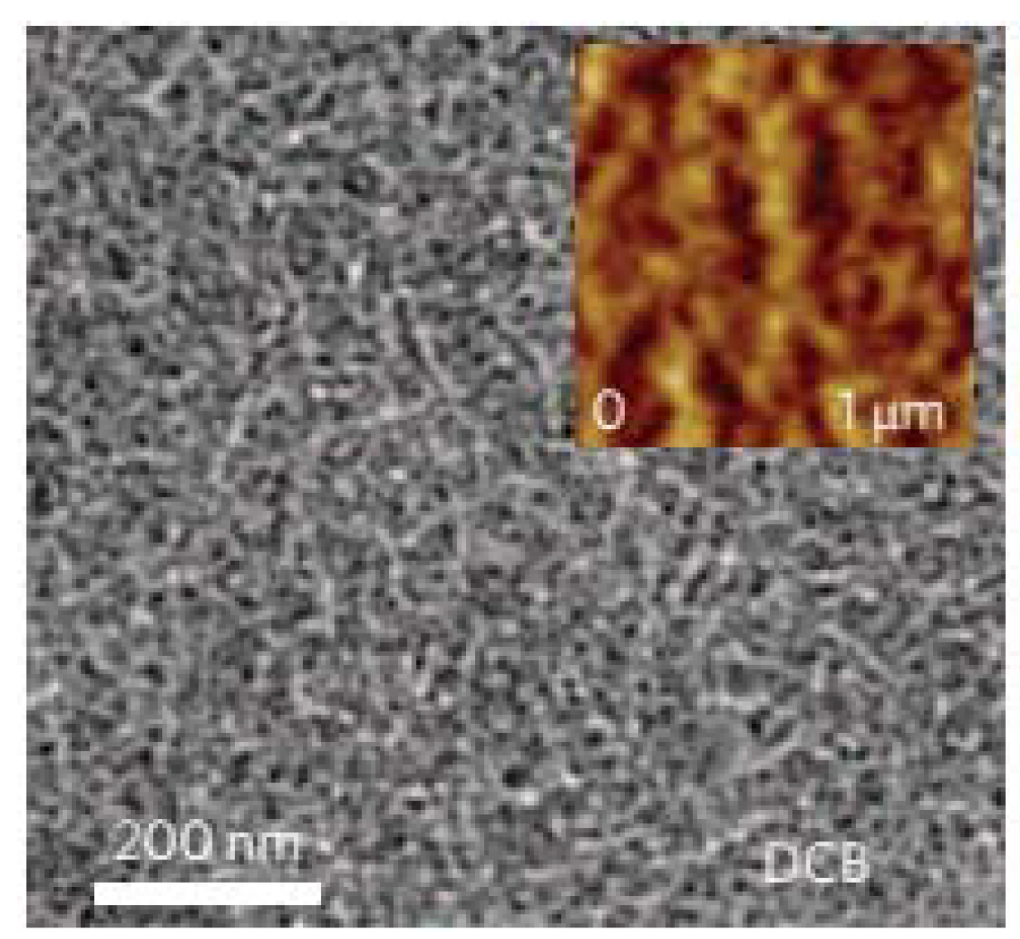
The D–A-blend ratio strongly affects the performance of BHJ solar cells. The D–A-blend ratio influences the sizes and distributions of the phases, thereby changing the size of the interface available for exciton dissociation and charge-carrier transport [62]. The blend composition of PCDTBT and PC70BM determines the formation of interpenetrated networks within the active layer of the device. The transmission electron microscope (TEM) and AFM images (Figure 8) of the PCDTBT:PC70BM (1:4) films produced using DCB showed well-defined nanoscale phase segregation of PC70BM without any further post-deposition treatment. The highly efficient electron scattering of PC70BM observed in the TEM image was due to a high concentration of PCBM [88].
Figure 8. AFM (inset) and transmission electron microscope (TEM) images of PCDTBT:PC70BM films spin-cast using DCB as a solvent. Reprinted with permission from Nature Publishing Group [88].
Energies 06 05847 g008
When the films with blend ratios of 1:1, 1:2, 1:3 and 1:4 were compared (Figure 9), it was observed that the fibrillar PCDTBT nanostructure of the film at 1:4 was most prominent, indicating that increasing the concentration of PC70BM causes the PCDTBT network to create longer and better-connected pathways. As a result, a device with an IQE approaching 100% in which almost all the absorbed photons were converted into electricity was fabricated. This device showed superior performance, with Jsc = 10.6 mA/cm2, Voc = 0.88 V, FF = 0.66 and PCE = 6.1% under AM 1.5 irradiation [88]. The optimal performance of an inverted zinc oxide nanoparticles/fullerene self-assembled monolayer (ZnO-NPs/C60-SAM)/P3HT:PCBM was investigated by varying the D–A-blend ratio from 1:0 to 1:1. The optimal performance of an inverted ZnO-NPs/C60-SAM/P3HT:PCBM was investigated by varying the D–A blend ratio from 1:0 to 1:1. PCE of the device increased from 1.6% to 3.5% at blend ratios of 1:0.3 to 1:0.4. Further increase in the ratio shows eventual saturation in PCE to 4.5%, thus indicating an optimum blend composition [62].
Figure 9. The effect of blending ratio on film morphology and device performance. (ad): TEM images of the PCDTBT:PC70BM blend films spin-cast using DCB with increasing amounts of PC70BM. The blending ratios are (a) 1:1; (b) 1:2; (c) 1:3; and (d) 1:4. Reprinted with permission from Nature Publishing Group [77].
Energies 06 05847 g009

5.4. Effects of Thermal and Solvent Annealing on the Active-Layer Morphology
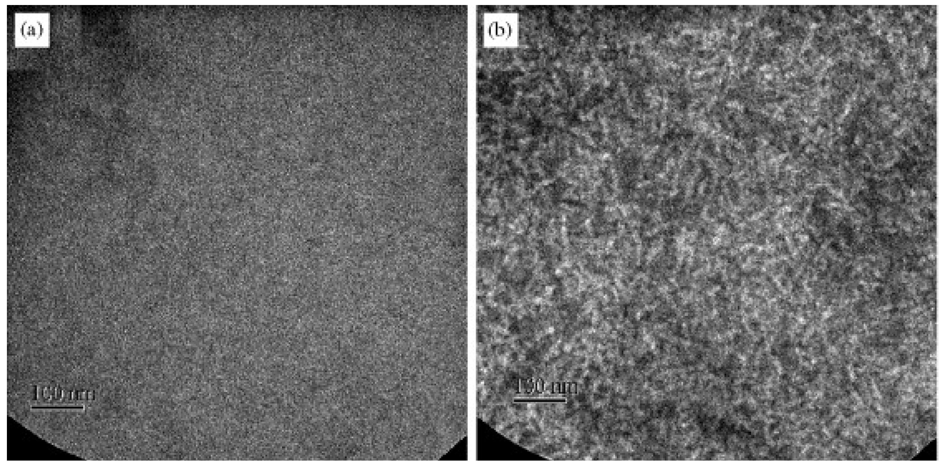
Thermal annealing is one of the simplest ways to improve the active-layer morphology. Heat treatment of the BHJ active layer causes re-ordering of the donor and acceptor phases to increase the size of the domain. Vanlaeke et al. [80] demonstrated that optimized thermal annealing of the BHJ layer can improve its photon-absorption properties, blend morphology and the hole mobility by inducing the stacking of P3HT in coplanar conjugated segments. A continuous and homogeneous morphology was displayed by as-spun P3HT:PCBM (1:1); however, clear, rod-like P3HT crystals with dimensions of approximately 10 × 30 nm appeared after an annealing treatment (Figure 10).
Figure 10. TEM images of a P3HT:PCBM 1:1 blend: (a) before and (b) after annealing at 100 °C. Reprinted with permission from Elsevier [80].
Energies 06 05847 g010
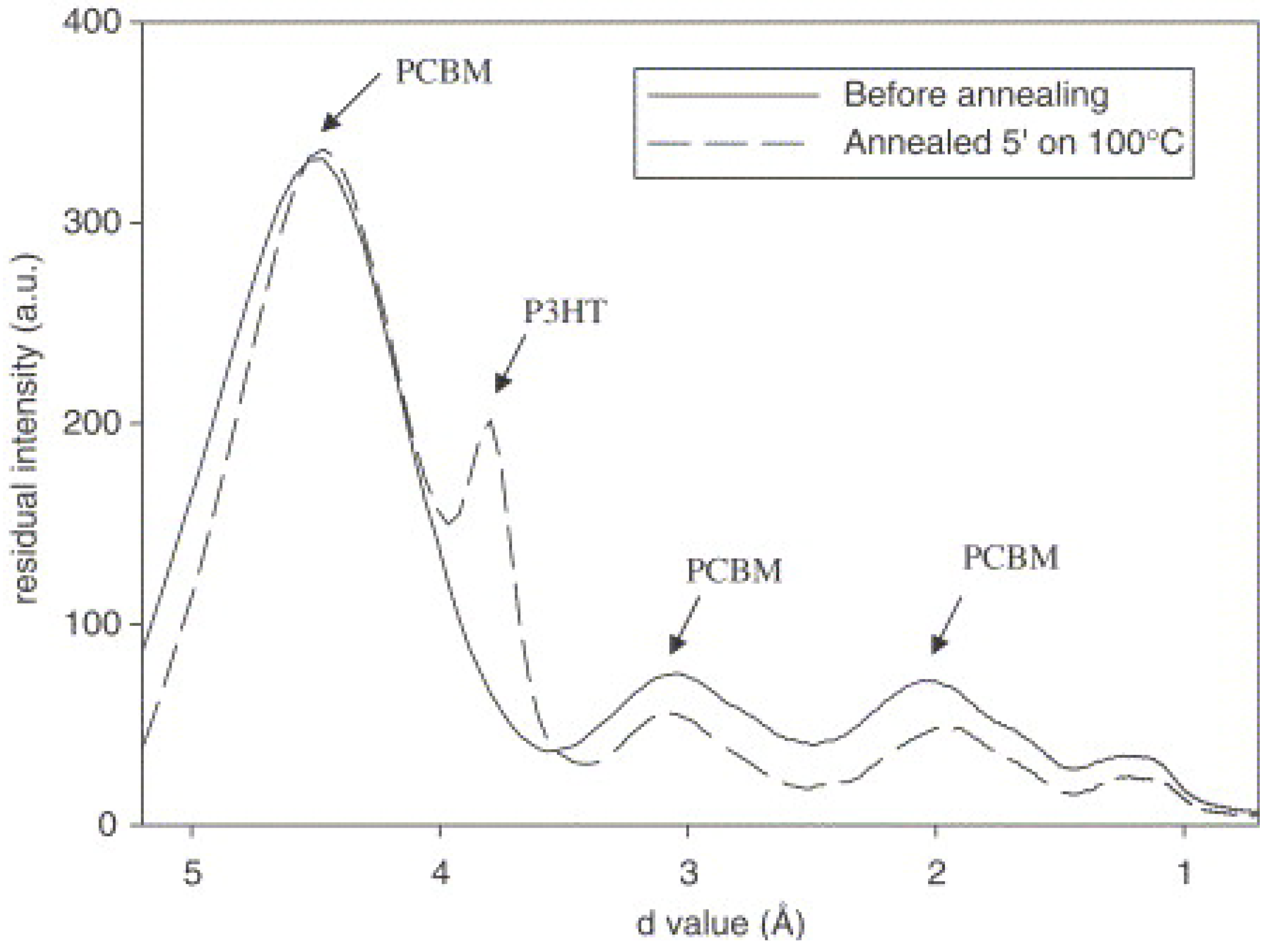
The TEM diffraction patterns of annealed P3HT:PCBM (1:2) revealed a distinct peak at 0.38 nm, which was attributed to crystalline P3HT. Several broad peaks were observed in the TEM diffraction pattern of the as-deposited film. They represented diffraction rings with average d-spacings of 0.46 nm, 0.31 nm and 0.21 nm resulting from nanocrystalline PCBM domains present in the blend (Figure 11).
Figure 11. TEM diffraction patterns of P3HT:PCBM 1:2 blend before and after annealing. Reprinted with permission from Elsevier [89].
Energies 06 05847 g011
The XRD spectra clearly show that the observed crystalline P3HT phase before annealing was further increased upon annealing. This also occurred in the film produced with a higher loading of PCBM (1:4), which displayed an amorphous phase before annealing [89]. Despite prolonged heat treatment, trace amounts of the casting solvents could still be found in the active layer [90,91]. The presence of residual solvent after thermal annealing leads to the formation of large PCBM agglomerates that cause extensive phase separation, thereby reducing the local photovoltaic efficiency of the device. A study of the morphology of P3HT:PCBM BHJ layers cast using o-DCB and CB, respectively, shows that a larger amount of o-DCB, a higher-boiling solvent, is retained within the BHJ active layer [92]. Liu et al. [50] investigated the performance of a BHJ active layer device fabricated using a P3HT:solution-processable functionalized graphene (P3HT:SPFGraphene) film before and after an annealing treatment. A significant improvement in the cell performance was observed in the device after annealing. The improved performance was attributed to the removal of unwanted functional groups and the recovery of π-conjugated regions, thereby enhancing the conductivity of the graphene sheets and the charge-carrier mobility [50]. It has been reported that prolonged thermal annealing leads to the macrophase segregation of P3HT and PCBM domains and subsequently deteriorates the performance of the BHJ device by inhibiting charge generation [93]. In addition, the use of high temperatures ranging from 120 °C to 150 °C limits the application of some inexpensive plastic substrates. Exposing the deposited organic layer (i.e., the active layer) to solvent vapour is a viable, inexpensive way to improve the performance of organic solar cells by increasing the molecular order of the blend. In contrast to the slow vaporization of a high-boiling solvent, which exposes the components to a concentrated solution and causes large-scale (10–100 nm) phase segregation, solvent vapour annealing (SVA) provides molecular mobility for local rearrangements instead of fully redissolving the components [70].
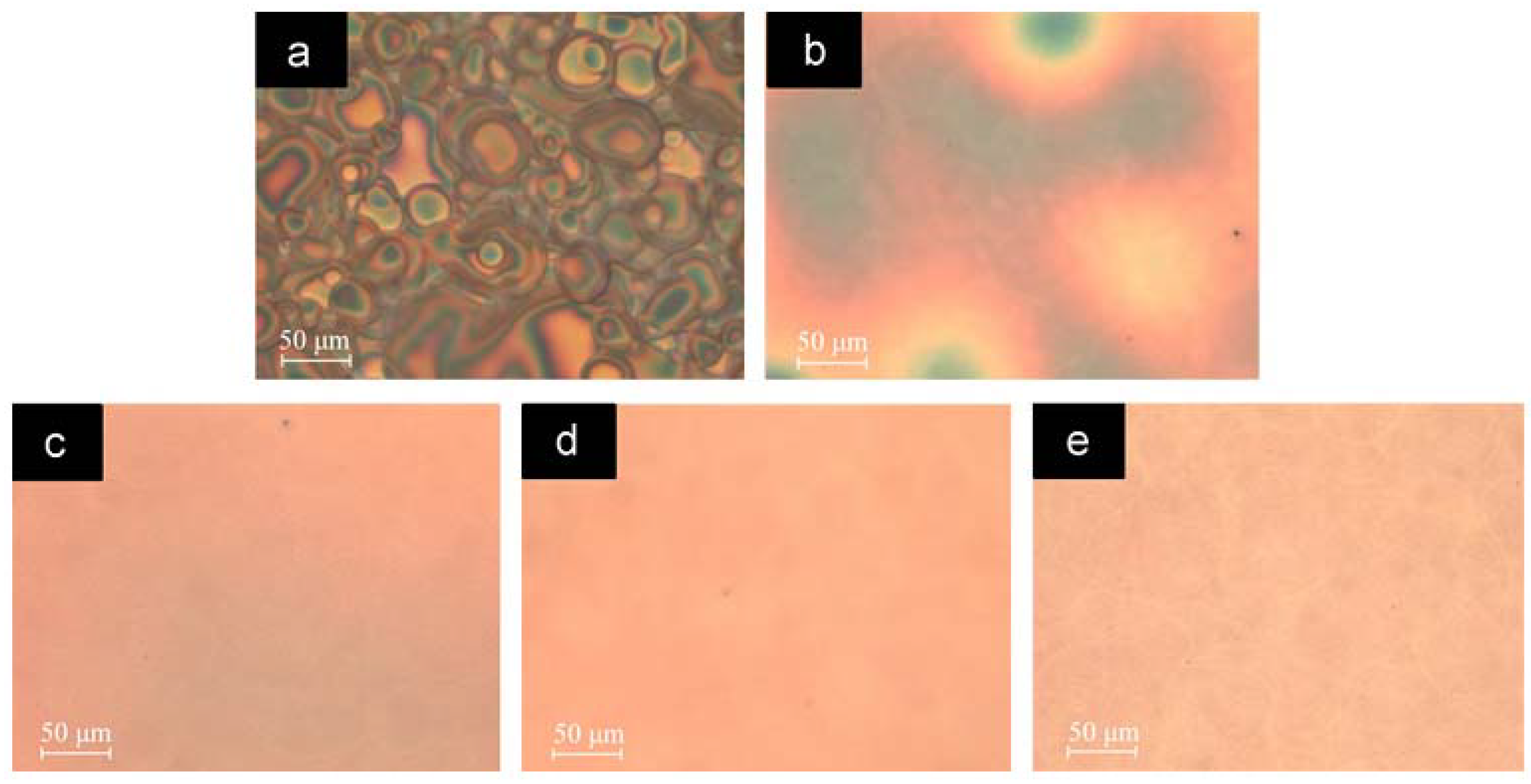
The effect of SVA on a polymer photovoltaic device with a blend of alternating poly-(thiophene-phenylene-thiophene) and PC71BM was studied [94]. Upon SVA, an alternating poly-[thiophene-phenylene-thiophene-(benzothiadiazole)]:PC71BM (a-PTPTBT:PC71BM) film exhibits a morphology that consists of well-defined blends of PCBM domains (with a grain size of approximately 20–30 nm) surrounded by a-PTPTBT domains that give rise to better phase separation between the polymer and PCBM molecules. A device with a high PCE of 6.4%, and with Jsc = 11.2 mA/cm2 and Voc = 0.85 V was obtained. Verploegen et al. [70] reported that CF and THF vapour annealing in a P3HT:PCBM-based device resulted in the swelling of the P3HT layers, causing a decrease in the π–π stacking distance, and eventually leading to rearrangement of the P3HT alkyl side chain as well as its backbone. Therefore, an increase in the P3HT crystalline order and induced nanoscale phase segregation of P3HT and PCBM were observed with a minimum reorientation of the P3HT crystallites. The authors concluded that SVA can lead to a favourable polymer-fullerene BHJ morphology for solar-cell devices [70]. This result was in agreement with that of Miller et al. [95]. This group exposed 1:1 composites of P3HT:PCBM thin film to CB vapour at room temperature. The Jsc increased from approximately 4.4 mA/cm2 to 10.9 mA/cm2 and the fill factor increased from 36% to 44%, resulting in a dramatic increase in the device PCE from 0.8% to 2.6%. AFM revealed some notable clusters of 10–20 nm on the surface of the annealed film as a result of the structure reordering that occurs via the diffusion of CB vapour. The structure reordering enabled the migration of PCBM and the reorganization of P3HT by softening the polymer nanocomposite. The more ordered structure provides better transport of the holes through the crystalline P3HT and electron transport via hopping through the PCBM [95]. The effects of SVA and the subsequent thermal annealing on an alternating phenylenevinylene copolymer:PCBM blend were investigated by Sharma et al. [72]. The DCB-annealed film had a better PCE (2.8%) than the thermal-annealed film (2.2%). However, the highest PCE (3.7%) was recorded for the DCB-treated blend that was subsequently subjected to thermal annealing. DCB-vapour-treated film that was subjected to thermal annealing not only had an ordered structure, but also possessed enhanced phase-separated networks for better charge separation and mobility. The surface morphology and the internal structure of the active layer of sprayed films can be uniformly reassembled using hot solvent vapour (HSV) annealing [96]. Unlike traditional SVA, which takes up to one hour to complete, HSV annealing takes only a few minutes to remove the inter-droplet boundary and reduce the shunt resistance (Rsh) (Figure 12) because of its effective penetration into the thin film, which allows it to uniformly reorder the internal structure and the surface morphology of the film.
Figure 12. Optical images of sprayed film subjected to a range of hot solvent vapour (HSV)-annealing processes: (a) as-sprayed film; (b) HSV-annealed film at 45 °C for 2 min; (c) HSV-annealed film at 45 °C for 4 min; (d) annealed film at 55 °C for 2 min; and (e) HSV-annealed film at 55 °C for 4 min. Reprinted with permission from Elsevier [87].
Energies 06 05847 g012
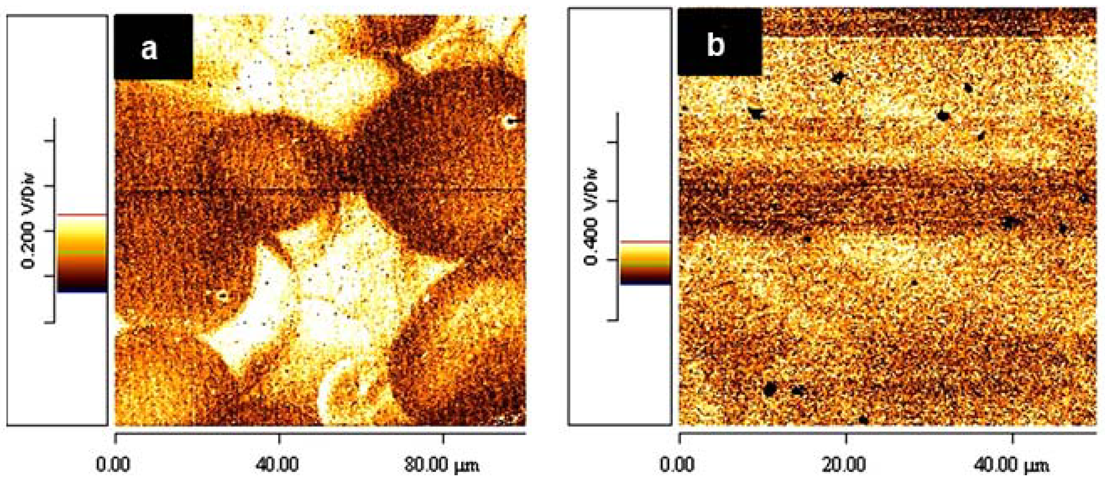
The conducting atomic force microscopy (C-AFM) images of the as-sprayed film and HSV-annealed film showed a substantial reduction in the RMS roughness of the as-sprayed film from 114.5 nm to 3.7 nm after HSV annealing (Figure 13).
This reduction indicates the removal of a large number of voids from the active layer, which reduces Rsh by preventing proper cathode-film interfacial contact [97]. Recently, Zhou et al. [98] studied the effect of methanol treatment on the efficiency of poly[[4,8-bis[(2-ethylhexyl)oxy]benzo[1,2-b:4,5-b]dithiophene-2,6-diyl][3-fluoro-2-[(2-ethylhexyl)carbonyl] thieno[3,4-]thiophenediyl]] (PTB7):PC71BM solar cells. Significant improvement in the device parameters (Voc, Jsc and FF) was recorded. The methanol treatment improved the charge transport and extraction properties of the device. Also, an improvement the built-in potential which has a direct impact on the Voc and the internal electric field profile in the devices was reported.
Figure 13. Conducting atomic force microscopy (C-AFM) images of (a) as-sprayed film; and (b) HSV-annealed film. Reprinted with permission from Elsevier [87].
Energies 06 05847 g013

5.5. Use of NWs to Control the Active-Layer Morphology

The use of preassembled conducting polymer NWs has been a key approach in controlling the nanoscale film morphology of BHJ solar cells. In this approach, efficient electrically bicontinuous nanoscale morphology can be realized without the need for the difficult phase-separation process. In addition, the vertical phase migration caused by thermal annealing, in which greater concentrations of P3HT are driven towards the top of the active layer while leaving much of the PCBM at the bottom, can be prevented with the use of polymer NW. The performance of polymer/fullerene BHJ solar cells based on conventional annealing-induced phase-separated poly(3-butylthiophene) (P3BT) has reportedly been poor [99,100,101,102]. The hole mobility in P3BT was nine times less than in regio-regular P3HT. This was attributed to poor crystalline aggregate formation in the P3BT films. However, Xin et al. [103] recorded identical PCE values of 3.0% for cells based on P3BT-NW:PC71BM (1:0.75) and for cells based on P3HT:PC71BM (1:1). P3BT NWs were prepared by heating a 6 mg/mL solution of P3BT in 1,2-dichlorobenzene (ODCB) and then slowly cooling it from 100 °C to room temperature in a dark environment to allow the formation of self-assembled P3BT NW. For P3BT-NW:PC61BM (1:1) blended film, a better PCE (2.2%) was obtained in comparison with P3BT:PC61BM with a similar ratio, which produced a PCE of 1%. This superior performance of solar cells based on P3BT-NW:PC61BM film was attributed to the formation of an interconnected network leading to a better charge-carrier mobility [103]. Rice et al. [77] employed a combination of P3HT NW and PCBM to control the vertical growth of the active-layer-material compositions that resulted from post-deposition heat treatment. As a result of the introduction of a pre-spin drying time, the device was fabricated with the addition of PCBM to the solution before and after NW self-assembly. Although the overall device performance trend was the same, a device fabricated from the post-PCBM addition was not as effective as the device made from the pre-PCBM addition. The authors demonstrated that the introduction of a pre-spin drying time and preformation of the donor phase NW increased the concentration of PCBM at the top of the active layer thereby induced a vertical phase gradient which is favorable for the standard device structure [77]. Kim et al. [16] investigated a method for optimizing the BHJ-device structure that made use of a solution of crystallized self-assembled P3HT NWs/PCBM prepared in DCM. The group correlated the ageing time of the P3HT precursor solution with the photovoltaic properties of the cell. It was found that at 60 h ageing time, maximum light absorption together with balanced charge-carrier mobility was recorded without post-production treatment. The Jsc and the PCE of the device were 9.51 mA/cm2 and 3.23%, respectively. An enhanced PCE efficiency of 3.94% was achieved when a pure P3HT donor phase was inserted into the hole-collecting electrode to serve as the buffer layer. This produced a multi-layered solar cell with a compositionally graded structure [16].

6. Conclusions and Outlook

The ever-increasing global human power consumption has highlighted the need for sustainable sources of power. Among others, solar power is an important renewable energy and in order to utilize such an enormous potential, different research areas have been established to develop an inexpensive, yet effective, device for capturing solar energy. PCE values approaching 10% have been achieved by D–A BHJ devices, but further improvement can be attained by controlling and optimizing the active-layer nanoscale morphology. Slow-drying techniques, solvent annealing and the use of conducting polymer NW have provided a notable insight into the importance of carefully controlled morphology as a function of effective device performance. However, optimized device performance will depend not only on control of the active-layer morphology, but also on material synthesis, durability and commercialization.

Acknowledgments

The authors acknowledge the financial support of the University of Malaya Research Grant (UMRG) grant number RG167-11AFR and the research grant from the Ministry of Science, Technology and Innovation (MOSTI) through E-Science grant number 06-01-03-SF0703.

Conflicts of Interest

The authors declare no conflict of interest.

References

  1. Bundgaard, E.; Krebs, F.C. Low band gap polymers for organic photovoltaics. Solar Energy Mater. Solar Cells 2007, 91, 954–985. [Google Scholar] [CrossRef]
  2. Irfan, U.; Wire, C. Novel Methods Store Sunshine as Fuel. Scientific American, 6 October 2011. [Google Scholar]
  3. Rothwarf, A.; Böer, K. Direct conversion of solar energy through photovoltaic cells. Prog. Solid State Chem. 1975, 10, 71–102. [Google Scholar] [CrossRef]
  4. Chen, J.-T.; Hsu, C.-S. Conjugated polymer nanostructures for organic solar cell applications. Polym. Chem. 2011, 2, 2707–2722. [Google Scholar] [CrossRef]
  5. Lewis, N.S. Toward cost-effective solar energy use. Science 2007, 315, 798–801. [Google Scholar] [CrossRef] [PubMed]
  6. Zoombelt, A.P.; Mathijssen, S.G.J.; Turbiez, M.G.R.; Wienk, M.M.; Janssen, R.A.J. Small band gap polymers based on diketopyrrolopyrrole. J. Mater. Chem. 2010, 20, 2240–2246. [Google Scholar] [CrossRef]
  7. Rahimi, R.; Roberts, A.; Narang, V.; Korakakis, D. Investigate the role of the active layers’ structures and morphology in the performance of the organic solar cell devices. Appl. Phys. Lett. 2013, 102, 073105:1–073105:3. [Google Scholar] [CrossRef]
  8. Narayanan, S.; Wenham, S.R.; Green, M.A. 17.8-percent efficiency polycrystalline silicon solar cells. IEEE Trans. Electron Devices 1990, 37, 382–384. [Google Scholar] [CrossRef]
  9. Soga, T. Nanostructured Materials for Solar Energy Conversion; Elsevier Science: Philadelphia, PA, USA, 2006; pp. 1–614. [Google Scholar]
  10. Forrest, S.R. The path to ubiquitous and low-cost organic electronic appliances on plastic. Nature 2004, 428, 911–918. [Google Scholar] [CrossRef] [PubMed]
  11. Guo, J.; Liang, Y.; Szarko, J.; Lee, B.; Son, H.J.; Rolczynski, B.S.; Yu, L.; Chen, L.X. Structure, dynamics, and power conversion efficiency correlations in a new low bandgap polymer: PCBM solar cell. J. Phys. Chem. B 2010, 114, 742–748. [Google Scholar] [CrossRef] [PubMed]
  12. Liang, Y.; Yu, L. Development of semiconducting polymers for solar energy harvesting. Polym. Rev. 2010, 50, 454–473. [Google Scholar] [CrossRef]
  13. Delgado, J.L.; Bouit, P.-A.; Filippone, S.; Herranz, M.Á.; Martín, N. Organic photovoltaics: A chemical approach. Chem. Commun. 2010, 46, 4853–4865. [Google Scholar] [CrossRef] [Green Version]
  14. Service, R.F. Outlook brightens for plastic solar cells. Science 2011, 332, 293. [Google Scholar] [CrossRef] [PubMed]
  15. You, J.; Dou, L.; Yoshimura, K.; Kato, T.; Ohya, K.; Moriarty, T.; Emery, K.; Chen, C.-C.; Gao, J.; Li, G.; et al. A polymer tandem solar cell with 10.6% power conversion efficiency. Nat. Commun. 2013, 4, 1446. [Google Scholar] [CrossRef] [PubMed]
  16. Kim, J.S.; Lee, J.H.; Park, J.H.; Shim, C.; Sim, M.; Cho, K. High‐efficiency organic solar cells based on preformed poly(3‐hexylthiophene) nanowires. Adv. Funct. Mater. 2011, 21, 480–486. [Google Scholar] [CrossRef]
  17. Ray, B.; Nair, P.R.; Alam, M.A. Unraveling the Role of Morphology on Organic Solar Cell Performance. 2012. arXiv:1011.0956. arXiv.org e-Print archive. Available online: http://arxiv.org/abs/1011.0956 (accessed on 30 June 2013).
  18. Moulé, A.J.; Meerholz, K. Morphology control in solution-processed bulk-heterojunction solar cell mixtures. Adv. Funct. Mater. 2009, 19, 3028–3036. [Google Scholar] [CrossRef]
  19. Schnabel, W. Photoconductivity. In Polymers and Light; Wiley-VCH Verlag GmbH & Co. KGaA: Weinheim, Germany, 2007; pp. 49–71. [Google Scholar]
  20. Hoppe, H.; Niggemann, M.; Winder, C.; Kraut, J.; Hiesgen, R.; Hinsch, A.; Meissner, D.; Sariciftci, N.S. Nanoscale morphology of conjugated polymer/fullerene-based bulk-heterojunction solar cells. Adv. Funct. Mater. 2004, 14, 1005–1011. [Google Scholar] [CrossRef]
  21. Günes, S.; Neugebauer, H.; Sariciftci, N.S. Conjugated polymer-based organic solar cells. Chem. Rev. 2007, 107, 1324–1338. [Google Scholar] [CrossRef] [PubMed]
  22. Blom, P.W.; Mihailetchi, V.D.; Koster, L.J.A.; Markov, D.E. Device physics of polymer: Fullerene bulk heterojunction solar cells. Adv. Mater. 2007, 19, 1551–1566. [Google Scholar] [CrossRef]
  23. Hoppe, H.; Glatzel, T.; Niggemann, M.; Schwinger, W.; Schaeffler, F.; Hinsch, A.; Lux-Steiner, M.C.; Sariciftci, N.S. Efficiency limiting morphological factors of MDMO-PPV:PCBM plastic solar cells. Thin Solid Films 2006, 511–512, 587–592. [Google Scholar] [CrossRef]
  24. Ratier, B.; Nunzi, J.-M.; Aldissi, M.; Kraft, T.M.; Buncel, E. Organic solar cell materials and active layer designs—Improvements with carbon nanotubes: A review. Polym. Int. 2012, 61, 342–354. [Google Scholar] [CrossRef]
  25. Thompson, B.C.; Fréchet, J.M. Polymer–Fullerene composite solar cells. Angew. Chem. Int. Ed. 2008, 47, 58–77. [Google Scholar] [CrossRef]
  26. Scharber, M.C.; Mühlbacher, D.; Koppe, M.; Denk, P.; Waldauf, C.; Heeger, A.J.; Brabec, C.J. Design rules for donors in bulk‐heterojunction solar cells—Towards 10% energy‐conversion efficiency. Adv. Mater. 2006, 18, 789–794. [Google Scholar] [CrossRef]
  27. Skompska, M. Hybrid conjugated polymer/semiconductor photovoltaic cells. Synth. Met. 2010, 160, 1–15. [Google Scholar] [CrossRef]
  28. Brabec, C.J.; Sariciftci, N.S.; Hummelen, J.C. Plastic solar cells. Adv. Funct. Mater. 2001, 11, 15–26. [Google Scholar] [CrossRef]
  29. Nishikitani, Y.; Uchida, S.; Kubo, T. Nanostructured Organic Bulk Heterojunction Solar Cells. In Nanostructured Materials for Solar Energy Conversion; Tetsuo, S., Ed.; Elsevier: Amsterdam, The Netherlands, 2006; Chapter 11; pp. 319–333. [Google Scholar]
  30. Cai, W.; Gong, X.; Cao, Y. Polymer solar cells: Recent development and possible routes for improvement in the performance. Solar Energy Mater. Solar Cells 2010, 94, 114–127. [Google Scholar] [CrossRef]
  31. Mozer, A.J.; Sariciftci, N.S. Conjugated polymer photovoltaic devices and materials. Comptes Rendus Chim. 2006, 9, 568–577. [Google Scholar] [CrossRef]
  32. Silvestri, F.; Irwin, M.D.; Beverina, L.; Facchetti, A.; Pagani, G.A.; Marks, T.J. Efficient squaraine-based solution processable bulk-heterojunction solar cells. J. Am. Chem. Soc. 2008, 130, 17640–17641. [Google Scholar] [CrossRef] [PubMed]
  33. Boudreault, P.-L.T.; Najari, A.; Leclerc, M. Processable low-bandgap polymers for photovoltaic applications. Chem. Mater. 2010, 23, 456–469. [Google Scholar] [CrossRef]
  34. Li, Y.; Guo, Q.; Li, Z.; Pei, J.; Tian, W. Solution processable D–A small molecules for bulk-heterojunction solar cells. Energy Environ. Sci. 2010, 3, 1427–1436. [Google Scholar] [CrossRef]
  35. Mandoc, M.M.; Koster, L.J.A.; Blom, P.W.M. Optimum charge carrier mobility in organic solar cells. Appl. Phys. Lett. 2007, 90, 133504:1–133504:3. [Google Scholar] [CrossRef]
  36. Yong, X.; Zhang, J. Theoretical investigations for organic solar cells. Mater. Technol. Adv. Perform. Mater. 2013, 28, 1–2. [Google Scholar]
  37. Vardeny, Z.V. Spin-enhanced organic bulk heterojunction photovoltaic solar cells. Nat. Commun. 2012, 3, 1043. [Google Scholar] [CrossRef] [PubMed]
  38. Moon, J.S.; Takacs, C.J.; Sun, Y.; Heeger, A.J. Spontaneous formation of bulk heterojunction nanostructures: Multiple routes to equivalent morphologies. Nano Lett. 2011, 11, 1036–1039. [Google Scholar] [CrossRef] [PubMed]
  39. Wienk, M.M.; Kroon, J.M.; Verhees, W.J.; Knol, J.; Hummelen, J.C.; van Hal, P.A.; Janssen, R.A. Efficient methano [70] fullerene/MDMO‐PPV bulk heterojunction photovoltaic cells. Angew. Chem. 2003, 115, 3493–3497. [Google Scholar] [CrossRef]
  40. Moon, J.S.; Jo, J.; Heeger, A.J. Nanomorphology of PCDTBT:PC70BM bulk heterojunction solar cells. Adv. Energy Mater. 2012, 2, 304–308. [Google Scholar] [CrossRef]
  41. Tong, M.; Coates, N.E.; Moses, D.; Heeger, A.J.; Beaupré, S.; Leclerc, M. Charge carrier photogeneration and decay dynamics in the poly (2,7-carbazole) copolymer PCDTBT and in bulk heterojunction composites with PC70 BM. Phys. Rev. B 2010, 81, 125210:1–125210:6. [Google Scholar] [CrossRef]
  42. Cheung, D.L.; Troisi, A. Theoretical study of the organic photovoltaic electron acceptor PCBM: Morphology, electronic structure, and charge localization. J. Phys. Chem. C 2010, 114, 20479–20488. [Google Scholar] [CrossRef]
  43. Mayer, A.C.; Scully, S.R.; Hardin, B.E.; Rowell, M.W.; McGehee, M.D. Polymer-based solar cells. Mater. Today 2007, 10, 28–33. [Google Scholar] [CrossRef]
  44. Valentini, L.; Bagnis, D.; Marrocchi, A.; Seri, M.; Taticchi, A.; Kenny, J.M. Novel anthracene-core molecule for the development of efficient PCBM-based solar cells. Chem. Mater. 2007, 20, 32–34. [Google Scholar] [CrossRef]
  45. Wang, S.; Bian, Z.; Xia, X.; Huang, C. Heterojunction organic solar cells based on donor-π-acceptor small molecule layers with controlled interface morphology. Org. Electron. 2010, 11, 1909–1915. [Google Scholar] [CrossRef]
  46. Talgorn, E.; Gao, Y.; Aerts, M.; Kunneman, L.T.; Schins, J.M.; Savenije, T.; van Huis, M.A.; van der Zant, H.S.; Houtepen, A.J.; Siebbeles, L.D. Unity quantum yield of photogenerated charges and band-like transport in quantum-dot solids. Nat. Nanotechnol. 2011, 6, 733–739. [Google Scholar] [CrossRef] [PubMed]
  47. Lee, J.-S.; Kovalenko, M.V.; Huang, J.; Chung, D.S.; Talapin, D.V. Band-like transport, high electron mobility and high photoconductivity in all-inorganic nanocrystal arrays. Nat. Nanotechnol. 2011, 6, 348–352. [Google Scholar] [CrossRef] [PubMed]
  48. Colbert, A.E.; Janke, E.M.; Hsieh, S.T.; Subramaniyan, S.; Schlenker, C.W.; Jenekhe, S.A.; Ginger, D.S. Hole transfer from low band gap quantum dots to conjugated polymers in organic/inorganic hybrid photovoltaics. J. Phys. Chem. Lett. 2013, 4, 280–284. [Google Scholar] [CrossRef]
  49. Etgar, L.; Moehl, T.; Gabriel, S.; Hickey, S.G.; Eychmüller, A.; Grätzel, M. Light energy conversion by mesoscopic PbS quantum dots/TiO2 heterojunction solar cells. ACS Nano 2012, 6, 3092–3099. [Google Scholar] [CrossRef] [PubMed]
  50. Liu, Q.; Liu, Z.; Zhang, X.; Yang, L.; Zhang, N.; Pan, G.; Yin, S.; Chen, Y.; Wei, J. Polymer photovoltaic cells based on solution‐processable graphene and P3HT. Adv. Funct. Mater. 2009, 19, 894–904. [Google Scholar] [CrossRef]
  51. Xu, Y.; Liu, Z.; Zhang, X.; Wang, Y.; Tian, J.; Huang, Y.; Ma, Y.; Zhang, X.; Chen, Y. A graphene hybrid material covalently functionalized with porphyrin: synthesis and optical limiting property. Adv. Mater. 2009, 21, 1275–1279. [Google Scholar] [CrossRef]
  52. Li, D.; Müller, M.B.; Gilje, S.; Kaner, R.B.; Wallace, G.G. Processable aqueous dispersions of graphene nanosheets. Nat. Nanotechnol. 2008, 3, 101–105. [Google Scholar] [CrossRef] [PubMed]
  53. Li, S.-S.; Tu, K.-H.; Lin, C.-C.; Chen, C.-W.; Chhowalla, M. Solution-processable graphene oxide as an efficient hole transport layer in polymer solar cells. ACS Nano 2010, 4, 3169–3174. [Google Scholar] [CrossRef] [PubMed]
  54. Stylianakis, M.M.; Spyropoulos, G.D.; Stratakis, E.; Kymakis, E. Solution-processable graphene linked to 3,5-dinitrobenzoyl as an electron acceptor in organic bulk heterojunction photovoltaic devices. Carbon 2012, 50, 5554–5561. [Google Scholar] [CrossRef]
  55. Bakhshi, A.; Kaur, A.; Arora, V. Molecular engineering of novel low band gap conducting polymers. Indian J. Chem. Part A Inorg. Phys. Theor. Anal. 2012, 51, 57–68. [Google Scholar]
  56. Roncali, J. Molecular engineering of the band gap of π‐conjugated systems: Facing technological applications. Macromol. Rapid Commun. 2007, 28, 1761–1775. [Google Scholar] [CrossRef]
  57. Roncali, J.; Frère, P.; Blanchard, P.; de Bettignies, R.; Turbiez, M.; Roquet, S.; Leriche, P.; Nicolas, Y. Molecular and supramolecular engineering of π-conjugated systems for photovoltaic conversion. Thin Solid Films 2006, 511, 567–575. [Google Scholar] [CrossRef] [Green Version]
  58. Chen, D.; Liu, F.; Wang, C.; Nakahara, A.; Russell, T.P. Bulk heterojunction photovoltaic active layers via bilayer interdiffusion. Nano Lett. 2011, 11, 2071–2078. [Google Scholar] [CrossRef] [PubMed]
  59. Weerakoon, K.A.; Auad, M.; Horikawa, S.; Chin, B.A. Effect of active layer morphology on poly3-hexylthiophene phytochemical chemiresistor sensor performance. IEEE Sens. J. 2012, 12, 3062–3068. [Google Scholar] [CrossRef]
  60. Balderrama, V.; Estrada, M.; Formentin, P.; Viterisi, A.; Ferre-Borrull, J.; Pallares, J.; Palomares, E.; Marsal, L. Influence and Relationship of Film Morphology on Organic Solar Cells Manufactured with Different P3HT:PC[70]BM Blend Solutions. In Proceedings of the 2011 8th International Conference on Electrical Engineering Computing Science and Automatic Control (CCE), Merida, Mexico, 26–28 October 2011; pp. 1–5.
  61. Haung, S.H.; Lu, P.Y.; Chung, C.L.; Fu, S.L. Preparation of Active Layer of Solar Cells Device by F8T2 Blending with PCBM. In Proceedings of the 2010 IEEE CPMT Symposium Japan, Tokyo, Japan, 24–26 August 2010; pp. 1–4.
  62. Hau, S.K.; O’Malley, K.M.; You-Jung, C.; Yip, H.-L.; Ma, H.; Jen, A.K.Y. Optimization of active layer and anode electrode for high-performance inverted bulk-heterojunction solar cells. IEEE J. Sel. Top. Quantum Electron. 2010, 16, 1665–1675. [Google Scholar] [CrossRef]
  63. Dang, M.T.; Wantz, G.; Bejbouji, H.; Urien, M.; Dautel, O.J.; Vignau, L.; Hirsch, L. Polymeric solar cells based on P3HT:PCBM: Role of the casting solvent. Solar Energy Mater. Solar Cells 2011, 95, 3408–3418. [Google Scholar] [CrossRef]
  64. Mihailetchi, V.D.; Xie, H.; de Boer, B.; Popescu, L.M.; Hummelen, J.C.; Blom, P.W.; Koster, L.J.A. Origin of the enhanced performance in poly(3-hexylthiophene): [6,6]-phenyl C61-butyric acid methyl ester solar cells upon slow drying of the active layer. Appl. Phys. Lett. 2006, 89, 012107:1–012107:3. [Google Scholar] [CrossRef]
  65. Li, G.; Shrotriya, V.; Huang, J.; Yao, Y.; Moriarty, T.; Emery, K.; Yang, Y. High-efficiency solution processable polymer photovoltaic cells by self-organization of polymer blends. Nat. Mater. 2005, 4, 864–868. [Google Scholar] [CrossRef]
  66. Xia, J.; Masaki, N.; Jiang, K.; Yanagida, S. The influence of doping ions on poly(3,4-ethylenedioxythiophene) as a counter electrode of a dye-sensitized solar cell. J. Mater. Chem. 2007, 17, 2845–2850. [Google Scholar] [CrossRef]
  67. Verploegen, E.; Mondal, R.; Bettinger, C.J.; Sok, S.; Toney, M.F.; Bao, Z. Effects of thermal annealing upon the morphology of polymer–fullerene blends. Adv. Funct. Mater. 2010, 20, 3519–3529. [Google Scholar] [CrossRef]
  68. Marsh, R.A.; Hodgkiss, J.M.; Albert-Seifried, S.; Friend, R.H. Effect of annealing on P3HT:PCBM charge transfer and nanoscale morphology probed by ultrafast spectroscopy. Nano Lett. 2010, 10, 923–930. [Google Scholar] [CrossRef] [PubMed]
  69. Zeng, L.; Tang, C.W.; Chen, S.H. Effects of active layer thickness and thermal annealing on polythiophene: Fullerene bulk heterojunction photovoltaic devices. Appl. Phys. Lett. 2010, 97, 053305:1–053305:3. [Google Scholar]
  70. Verploegen, E.; Miller, C.E.; Schmidt, K.; Bao, Z.; Toney, M.F. Manipulating the morphology of P3HT-PCBM bulk heterojunction blends with solvent vapor annealing. Chem. Mater. 2012, 24, 3923–3931. [Google Scholar] [CrossRef]
  71. Tang, H.; Lu, G.; Li, L.; Li, J.; Wang, Y.; Yang, X. Precise construction of PCBM aggregates for polymer solar cells via multi-step controlled solvent vapor annealing. J. Mater. Chem. 2010, 20, 683–688. [Google Scholar] [CrossRef]
  72. Sharma, G.D.; Suresh, P.; Sharma, S.S.; Vijay, Y.K.; Mikroyannidis, J.A. Effect of solvent and subsequent thermal annealing on the performance of phenylenevinylene copolymer:PCBM solar cells. ACS Appl. Mater. Interfaces 2010, 2, 504–510. [Google Scholar] [CrossRef] [PubMed]
  73. Truong, Q.N.N.; Truong, N.T.N.; Park, C.; Jung, J.H. Study of MEH–PPV/PCBM active layer morphology and its application for hybrid solar cell performance. Bull. Mater. Sci. 2012, 35, 277–281. [Google Scholar] [CrossRef]
  74. Shen, Y.-M.; Chen, C.-S.; Yang, P.-C.; Ma, S.-Y.; Lin, C.-F. Improvement of surface morphology of thin films and performance by applying electric field on P3HT:PCBM based solar cells. Solar Energy Mater. Solar Cells 2012, 99, 263–267. [Google Scholar] [CrossRef]
  75. Lou, S.J.; Szarko, J.M.; Xu, T.; Yu, L.; Marks, T.J.; Chen, L.X. Effects of additives on the morphology of solution phase aggregates formed by active layer components of high-efficiency organic solar cells. J. Am. Chem. Soc. 2011, 133, 20661–20663. [Google Scholar] [CrossRef] [PubMed]
  76. Kim, Y.; Kim, G.; Lee, J.; Lee, K. Morphology controlled bulk-heterojunction layers of fully electro-spray coated organic solar cells. Solar Energy Mater. Solar Cells 2012, 105, 272–279. [Google Scholar] [CrossRef]
  77. Rice, A.H.; Giridharagopal, R.; Zheng, S.X.; Ohuchi, F.S.; Ginger, D.S.; Luscombe, C.K. Controlling vertical morphology within the active layer of organic photovoltaics using poly(3-hexylthiophene) nanowires and phenyl-C61-butyric acid methyl ester. ACS Nano 2011, 5, 3132–3140. [Google Scholar] [CrossRef] [PubMed]
  78. De Freitas, J.N.; Nogueira, A.F. Incorporation of Inorganic Nanoparticles into Bulk Heterojunction Organic Solar Cells. In Nanoenergy; Springer-Verlag: Heidelberg, Germany, 2013; pp. 1–47. [Google Scholar]
  79. Zhang, F.-Z.; Kato, T.; Fuji, M.; Takahashi, M. Gelcasting fabrication of porous ceramics using a continuous process. J. Eur. Ceram. Soc. 2006, 26, 667–671. [Google Scholar] [CrossRef]
  80. Vanlaeke, P.; Vanhoyland, G.; Aernouts, T.; Cheyns, D.; Deibel, C.; Manca, J.; Heremans, P.; Poortmans, J. Polythiophene based bulk heterojunction solar cells: Morphology and its implications. Thin Solid Films 2006, 511–512, 358–361. [Google Scholar] [CrossRef]
  81. Kim, Y.; Lee, Y.; Kim, J.K.; Seo, E.-O.; Lee, E.-W.; Lee, W.; Han, S.-H.; Lee, S.-H. Effect of solvents on the performance and morphology of polymer photovoltaic devices. Curr. Appl. Phys. 2010, 10, 985–989. [Google Scholar] [CrossRef]
  82. Lin, S.-H.; Lan, S.; Sun, J.-Y.; Lin, C.-F. Influence of mixed solvent on the morphology of the P3HT:Indene-C60 bisadduct (ICBA) blend film and the performance of inverted polymer solar cells. Org. Electron. 2013, 14, 26–31. [Google Scholar] [CrossRef]
  83. Jang, S.K.; Gong, S.C.; Chang, H.J. Effects of various solvent addition on crystal and electrical properties of organic solar cells with P3HT:PCBM active layer. Synth. Met. 2012, 162, 426–430. [Google Scholar] [CrossRef]
  84. Hu, X.; Wang, M.; Huang, F.; Gong, X.; Cao, Y. 23% Enhanced efficiency of polymer solar cells processed with 1-chloronaphthalene as the solvent additive. Synth. Met. 2013, 164, 1–5. [Google Scholar] [CrossRef]
  85. Moon, J.S.; Takacs, C.J.; Cho, S.; Coffin, R.C.; Kim, H.; Bazan, G.C.; Heeger, A.J. Effect of processing additive on the nanomorphology of a bulk heterojunction material. Nano Lett. 2010, 10, 4005–4008. [Google Scholar] [CrossRef] [PubMed]
  86. Salim, T.; Wong, L.H.; Brauer, B.; Kukreja, R.; Foo, Y.L.; Bao, Z.; Lam, Y.M. Solvent additives and their effects on blend morphologies of bulk heterojunctions. J. Mater. Chem. 2011, 21, 242–250. [Google Scholar] [CrossRef]
  87. Keawprajak, A.; Piyakulawat, P.; Klamchuen, A.; Iamraksa, P.; Asawapirom, U. Influence of crystallizable solvent on the morphology and performance of P3HT:PCBM bulk-heterojunction solar cells. Solar Energy Mater. Solar Cells 2010, 94, 531–536. [Google Scholar] [CrossRef]
  88. Park, S.H.; Roy, A.; Beaupré, S.; Cho, S.; Coates, N.; Moon, J.S.; Moses, D.; Leclerc, M.; Lee, K.; Heeger, A.J. Bulk heterojunction solar cells with internal quantum efficiency approaching 100%. Nat. Photonics 2009, 3, 297–302. [Google Scholar] [CrossRef]
  89. Vanlaeke, P.; Swinnen, A.; Haeldermans, I.; Vanhoyland, G.; Aernouts, T.; Cheyns, D.; Deibel, C.; D’Haen, J.; Heremans, P.; Poortmans, J.; et al. P3HT/PCBM bulk heterojunction solar cells: Relation between morphology and electro-optical characteristics. Solar Energy Mater. Solar Cells 2006, 90, 2150–2158. [Google Scholar] [CrossRef]
  90. Frank, C.W.; Rao, V.; Despotopoulou, M.M.; Pease, R.F.W.; Hinsberg, W.D.; Miller, R.D.; Rabolt, J.F. Structure in thin and ultrathin spin-cast polymer films. Science 1996, 273, 912–915. [Google Scholar] [CrossRef] [PubMed]
  91. Hadj Romdhane, I.; Price, P.E.; Miller, C.A.; Benson, P.T.; Wang, S. Drying of glassy polymer films. Ind. Eng. Chem. Res. 2001, 40, 3065–3075. [Google Scholar] [CrossRef]
  92. Chang, L.; Lademann, H.W.; Bonekamp, J.B.; Meerholz, K.; Moulé, A.J. Effect of trace solvent on the morphology of P3HT:PCBM bulk heterojunction solar cells. Adv. Funct. Mater. 2011, 21, 1779–1787. [Google Scholar] [CrossRef]
  93. Nagarjuna, G.; Venkataraman, D. Strategies for controlling the active layer morphologies in OPVs. J. Polym. Sci. Part B Polym. Phys. 2012, 50, 1045–1056. [Google Scholar] [CrossRef]
  94. Chen, Y.-C.; Yu, C.-Y.; Fan, Y.-L.; Hung, L.-I.; Chen, C.-P.; Ting, C. Low-bandgap conjugated polymer for high efficient photovoltaic applications. Chem. Commun. 2010, 46, 6503–6505. [Google Scholar] [CrossRef]
  95. Miller, S.; Fanchini, G.; Lin, Y.-Y.; Li, C.; Chen, C.-W.; Su, W.-F.; Chhowalla, M. Investigation of nanoscale morphological changes in organic photovoltaics during solvent vapor annealing. J. Mater. Chem. 2008, 18, 306–312. [Google Scholar] [CrossRef]
  96. Huang, Y.-C.; Chia, H.-C.; Chuang, C.-M.; Tsao, C.-S.; Chen, C.-Y.; Su, W.-F. Facile hot solvent vapor annealing for high performance polymer solar cell using spray process. Solar Energy Mater. Solar Cells 2013, 114, 24–30. [Google Scholar] [CrossRef]
  97. Kim, M.-S.; Kim, B.-G.; Kim, J. Effective variables to control the fill factor of organic photovoltaic cells. ACS Appl. Mater. Interfaces 2009, 1, 1264–1269. [Google Scholar] [CrossRef] [PubMed]
  98. Zhou, H.; Zhang, Y.; Seifter, J.; Collins, S.D.; Luo, C.; Bazan, G.C.; Nguyen, T.-Q.; Heeger, A.J. High-efficiency polymer solar cells enhanced by solvent treatment. Adv. Mater. 2013, 25, 1646–1652. [Google Scholar] [CrossRef] [PubMed]
  99. Babel, A.; Jenekhe, S.A. Alkyl chain length dependence of the field-effect carrier mobility in regioregular poly(3-alkylthiophene)s. Synth. Met. 2005, 148, 169–173. [Google Scholar] [CrossRef]
  100. Nguyen, L.H.; Hoppe, H.; Erb, T.; Günes, S.; Gobsch, G.; Sariciftci, N.S. Effects of annealing on the nanomorphology and performance of poly(alkylthiophene):Fullerene bulk-heterojunction solar cells. Adv. Funct. Mater. 2007, 17, 1071–1078. [Google Scholar] [CrossRef]
  101. Yang, X.; Loos, J.; Veenstra, S.C.; Verhees, W.J.H.; Wienk, M.M.; Kroon, J.M.; Michels, M.A.J.; Janssen, R.A.J. Nanoscale morphology of high-performance polymer solar cells. Nano Lett. 2005, 5, 579–583. [Google Scholar] [CrossRef] [PubMed]
  102. Hiorns, R.C.; de Bettignies, R.; Leroy, J.; Bailly, S.; Firon, M.; Sentein, C.; Khoukh, A.; Preud’homme, H.; Dagron-Lartigau, C. High molecular weights, polydispersities, and annealing temperatures in the optimization of bulk-heterojunction photovoltaic cells based on poly(3-hexylthiophene) or poly(3-butylthiophene). Adv. Funct. Mater. 2006, 16, 2263–2273. [Google Scholar] [CrossRef]
  103. Xin, H.; Kim, F.S.; Jenekhe, S.A. Highly efficient solar cells based on poly(3-butylthiophene) nanowires. J. Am. Chem. Soc. 2008, 130, 5424–5425. [Google Scholar] [CrossRef] [PubMed]