1. Introduction
Gas turbines have, during the last decades, become more common as a power generating engine due to their flexibility and low specific investment costs. Development of gas turbines for power generation has gone hand in hand with the development of new gas turbines for use in aircraft engines. This increase in the proportion of gas turbine and combined-cycle units in power generation grids will affect the grid characteristics because of the gas turbine performance. Gas turbines will behave differently than other prime movers, e.g., hydroelectric units, when a frequency drop occurs in the system [
1]. The difference occurs because the dynamic behavior of the gas turbine depends on its rotational speed, which is proportional to the grid frequency. A drop in the grid frequency lowers the rotational speed of the gas turbine which affects the performance of the gas turbine and this can lead to unit instability during large frequency dips [
2]. This issue is more crucial when the gas turbine is used in an isolated grid or in grids with large renewable energy capacity and smart grids. To have a good frequency regulation in a power grid, there should be a balance between production and demand. Unfortunately, the amount of energy that is supplied by renewable energy resources such as wind and solar energy to the grid is not controllable. In other words, unlike conventional sources of electric power, these renewable sources are not “dispatchable” [
3]. Consequently, in smart grid and intermittent renewable energy dominated power grids, the fossil fuel units are usually responsible for grid frequency regulation and these units should be able to compensate the variation in power production of renewable energy units. Therefore, the fossil fuel in these grids should be able to respond faster and their performance should be more tolerant to frequency changes.
In modern combined-cycle power plants, the steam part is usually working on sliding pressure for higher efficiency, which means that there is not a lot of energy stored in the steam cycle that can be used for fast transient response. To respond to a frequency drop, the gas turbine must provide the energy to the steam cycle but it takes a while (in the order of 20 s) before the increase in fuel flow into the gas turbine combustion chamber affects the steam production. Therefore, in modern combined-cycle power plants, the transient performance of the unit depends entirely on gas turbine performance. Consequently, it would be reasonable to neglect the transient response of the steam part in analyzing the unit performance during frequency drops [
4].
Single-shaft gas turbines are usually used in combined-cycle power plants and large power generation units because of their simplicity, lower cost, no gearbox, better heat recovery and, as a result, higher efficiency. In single-shaft gas turbines, compressor, turbine and generator are located on an identical shaft. This configuration increases the generator’s inertia and consequently, it would minimize the speed reduction, if there is a step increase in engine load. Also, they are faster than multi shaft engines because there is no lag while a gas generator accelerates to increase the exhaust gas power to accelerate the free power turbine [
5]. On the other hand, reduction in grid frequency would decrease the compressor speed and as a result the air mass flow rate will also decrease during frequency dips. This reduction in air mass flow rate will put limitation on the amount of engine overfueling to protect the engine from overheating. Engine overfueling is required to accelerate the turbine to recover the frequency and this limitation may lead to unit instability in large frequency dips or near full load condition [
6]. This phenomenon is an inherent problem of the single-shaft gas turbines and it has nothing to do with the controller design.
Another way of combining steam and gas turbine is the steam-injected gas turbine (STIG). In the STIG, the hot exhaust gases from the gas turbine heats water to produce steam in a heat recovery steam generator. The steam is then led back to the gas turbine expander. This would result in higher efficiency, higher output power and lower emissions [
7]. There have been many different ways of injecting steam. The steam is injected to the combustor liners for power augmentation but it would be injected into or around the fuel nozzles to reduce the NO
x levels [
8,
9,
10,
11]. Today, the STIG cycle is commercially available around the world.
The objective of this paper is to study how steam injection into the combustion chamber can improve the transient performance of gas turbines during frequency drops. This paper presents a control algorithm based on an event-based control approach. This means that if a frequency drop occurs, the controller uses steam injection to help the main control loop to recover the frequency. When the frequency reaches its predefined value, the system then continues with its regular control algorithm. The performance of the proposed control algorithm is investigated under different scenarios during the frequency drops in island mode, which can be known as the extreme case in frequency regulation. Also, the effect of application of the new control algorithm on important gas turbine variable such as surge margin is considered in this paper.
This paper is organized in six sections. First, the regular control logic of the gas turbine and it shortcomings are discussed.
Section 3 presents the proposed solution and detail of new control system. It follows by a discussion about the effect of the steam injection on the surge margin. The simulation results and conclusions are presented in
Section 5 and
Section 6.
2. Regular Gas Turbine Control System and its Shortcomings
Gas turbines are usually equipped with a complicated control system and include several different loops such as governor, temperature controller, acceleration controller,
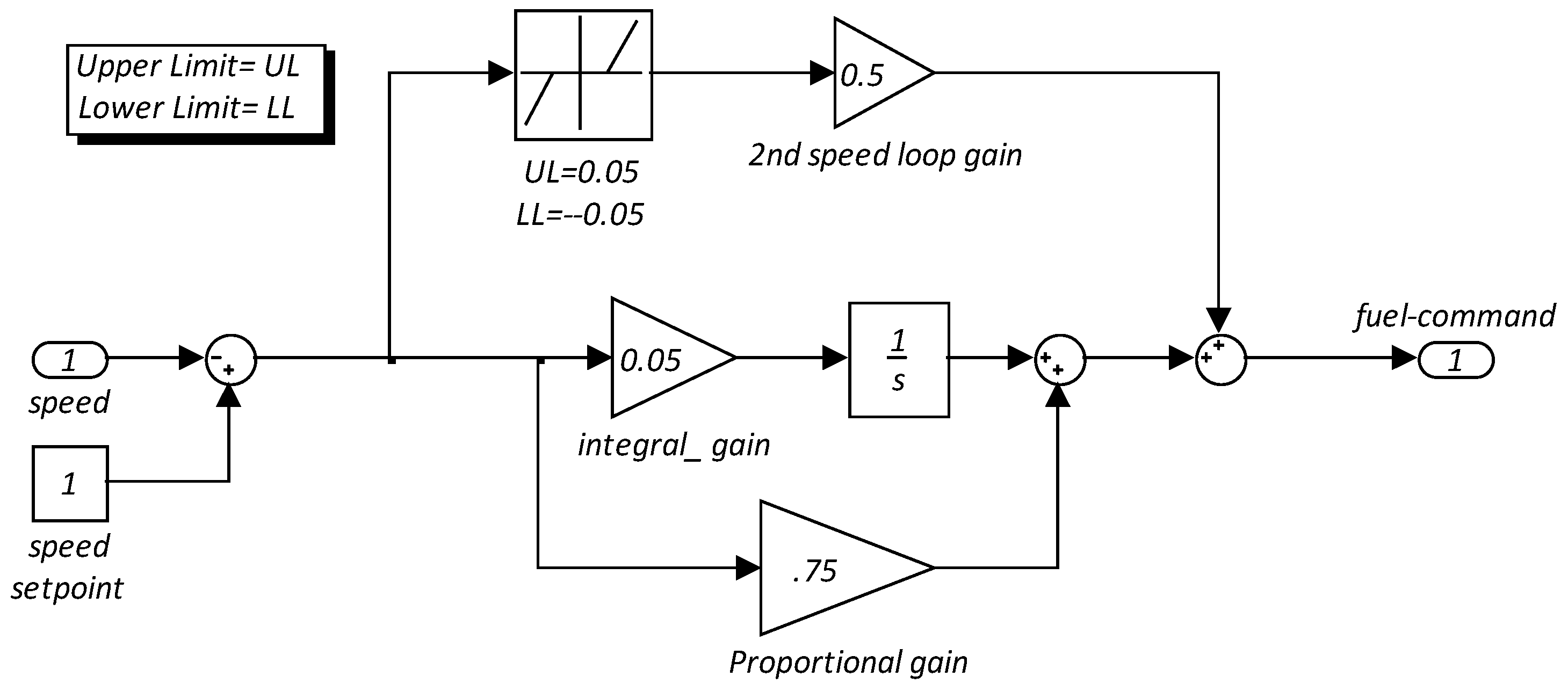
etc. The governor and temperature controller loop are the main control loops that affect the performance of the gas turbine during frequency dips. For this reason, only these two control loops will be considered here. The governor is known as the main control loop and it controls the gas turbine during normal operation. It adjusts the fuel flow into the combustion chamber so that the power output and speed will be equal to whatever the operator requires. Moreover, in combined-cycle power plants, the gas turbine exhaust temperature should be kept as high as possible for better heat recovery because it results in a higher overall efficiency. In order to maximize exhaust temperature, the temperature controller closes the inlet guide vanes (IGVs) to reduce the air mass flow rate through the engine in part load. The temperature controller also maintains the temperature of gas turbine components within the design range for safe and reliable operation. Consequently, the temperature controller can also reduce the fuel flow into the combustion chamber when the firing temperature reaches to its limit. The overheating protection loop is only activated in the fast engine loading or when the engine is working near its full load condition. The detail of the governor and temperature controller for a sample gas turbine is given in
Appendix A.
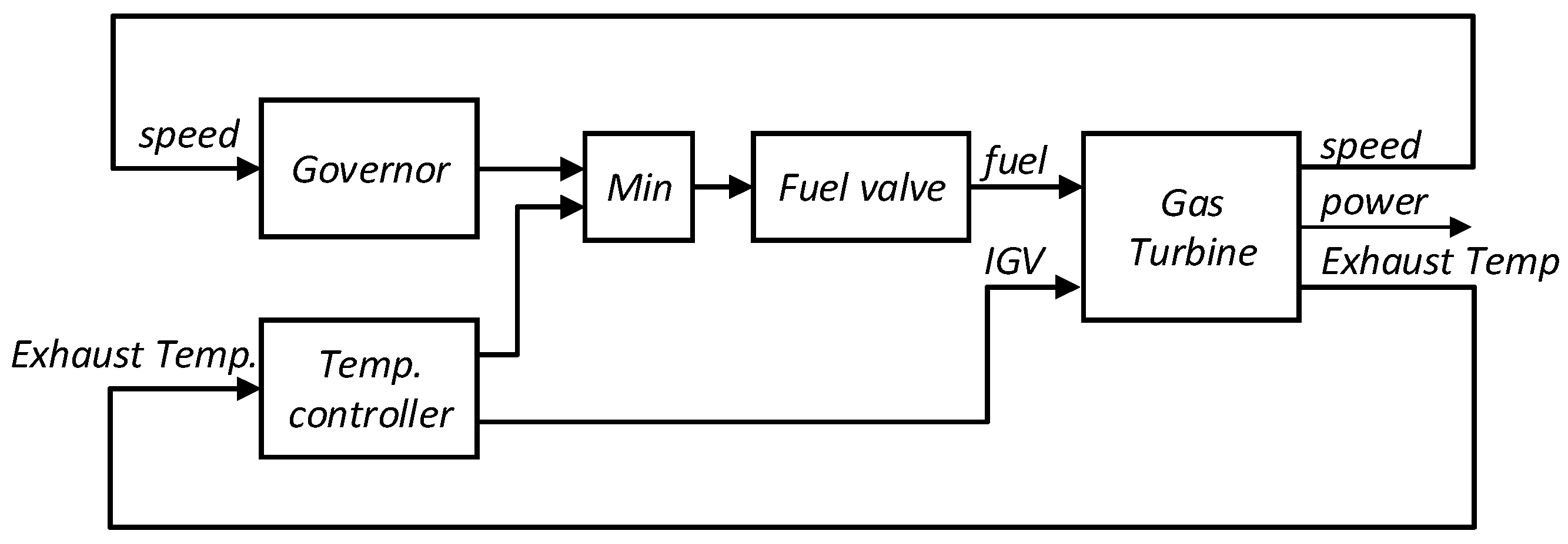
Figure 1 shows how the governor and the temperature control loop are connected to other components. The fuel flow calculated by the governor and the temperature controller are fed into a low vale selector (min) and their minimum is applied to the engine. This control logic provides a bumpless transfer between different control loops and this also means that at each moment only one controller is active. Although this control structure is very efficient and convenient under most of the operating conditions, it has two inherent problems in handling large frequency dips.
Figure 1.
Gas turbine regular control configuration in island mode.
Figure 1.
Gas turbine regular control configuration in island mode.
2.1. Gas Turbine Cannot Recover Frequency Dips near Full Load Condition
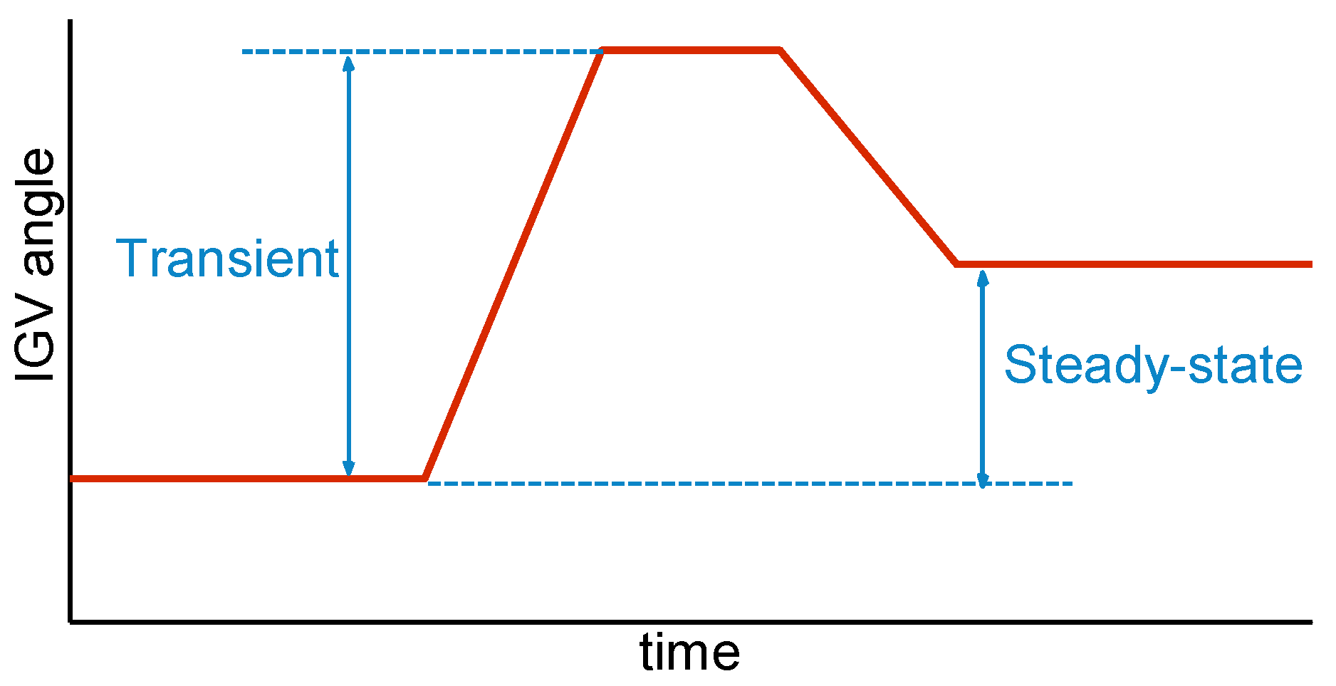
In single-shaft gas turbines, the compressor and generator are connected together. Therefore, during frequency dips, the compressor will rotate with a speed that is lower than its design speed. This reduction in rotational speed will lead to a decrease in air mass flow rate through the engine and result in a higher firing temperature. This is a transient effect and as soon as the gas turbine recovers the frequency, the air mass flow will be recovered as well. Additionally, the frequency drop is the consequence of higher power demand in the grid, so the control algorithm should apply more fuel to the combustion chamber to meet the new demand. The control algorithm will also need to provide some overfueling to accelerate the turbine so that it can recover the frequency at the same time. The fuel, which is related to new power demand, is required even after the frequency recovery but the overfueling which is related to turbine acceleration is a transient effect and it is not necessary after the speed returns to its nominal value. More fuel into the combustion chamber means a higher firing temperature, so the control algorithm tries to open the IGVs further and increase the air mass flow through the turbine to protect the engine from overheating. The IGV opening should be able to compensate all of the three effects, the air mass flow decrease because of reduced speed, overfueling for turbine acceleration and more fuel for the new power demand. The first two effects are transient and they are not necessary after the frequency is recovered but the IGV opening for the new power demand should be maintained even after frequency recovery. The required IGV opening is shown in
Figure 2 schematically.
Figure 2.
Schematic IGVs opening during frequency dips.
Figure 2.
Schematic IGVs opening during frequency dips.
There is no problem with current control logic until the turbine is near full load condition. Near full load, the IGVs are almost fully open and this means that the controller doesn’t have the needed reserve in IGVs which is required to provide the necessary air flow through the engine. This means that the firing temperature reaches its limit and the temperature controller will therefore reduce the fuel flow into the combustion chamber and will prevent the turbine from being loaded further. This leads to a continuous decrease in speed and creates a negative spiral that renders the gas turbine unstable. This situation is not acceptable when the IGVs have the reserve for new load demand but not enough reserve for the turbine acceleration and compensating the reduction in air mass flow because of speed reduction, since they are just needed for short period of time.
2.2. Slow Response of the Gas Turbine
The air flow dynamic is slower than the fuel flow dynamic. Fuel can be added directly into the combustion chamber, which means that it affects the output power and firing temperature quickly. On the other hand, to increase the air flow, the IGVs should be opened first and then the air accelerates and passes through the compressor stages to reach to the combustion chamber. Therefore, it affects the power output and firing temperature with a lag. This is due to the air inertia and IGV’s actuator speed which is usually slower in comparison to a fuel valve. The time it takes for the gas turbine to respond to a frequency dip is therefore dominated by the airflow dynamic. This is important because a fast response to a new power demand is equivalent to a smaller decrease in speed. The smaller speed reduction means less reduction in airflow and less overfueling for turbine acceleration. Consequently, the gas turbine governor can recover the frequency easier without reaching the safety temperature limits.
Although some solutions such as using fast IGVs actuator [
12], using the IGVs to load the engine and fuel to control the firing temperature [
13] and application of new control algorithms [
14] are suggested to solve these problems, but they are just useful for second problem and they have nothing to do with the first problem.
3. Proposed Solution
The proposed solution is to use steam injection into the combustion chamber as an auxiliary input to cover the shortcoming of current control algorithm during large frequency drops and frequency dips near full load condition. The application of steam injection is beneficial for several reasons. First of all, it augments the output power of the gas turbine by increasing the mass flow and heat capacity of working fluid through the turbine [
5]. Also, because the steam is injected directly into the combustion chamber, it affects the output power very fast. Moreover, the effect of steam injection, like fuel flow, doesn’t depend on the speed of the gas turbine because it doesn’t need to wait for the increase in airflow. Additionally, steam injection reduces the firing temperature of the gas turbine and therefore, the governor can overfuel the engine without reaching safety temperature limits. It also reduces the gas turbine emissions [
15,
16,
17] and increases the service life of the engine components by decreasing the peak temperature in the combustion chamber during the transient maneuvers. On the other hand, it has its own drawbacks; steam injection might reduce the compressor surge margin [
18] and also, it needs treated and purified water; otherwise it will affect the blade life [
7].
Application of this auxiliary input will be with an event-based control approach. It means, only if the frequency drop passes a certain limit, the controller will use steam injection to help the governor to recover the frequency and when the speed reaches its predefined value, the controller will stop the steam injection. It should be noted that, in combined-cycle power plants or in combined heat and power (CHP) units, the required steam is already at hand and new control system can be implemented easily with a small modification in original system. Also, for small amount of steam injection, there is no need for gas turbine or combustion chamber modification [
19].
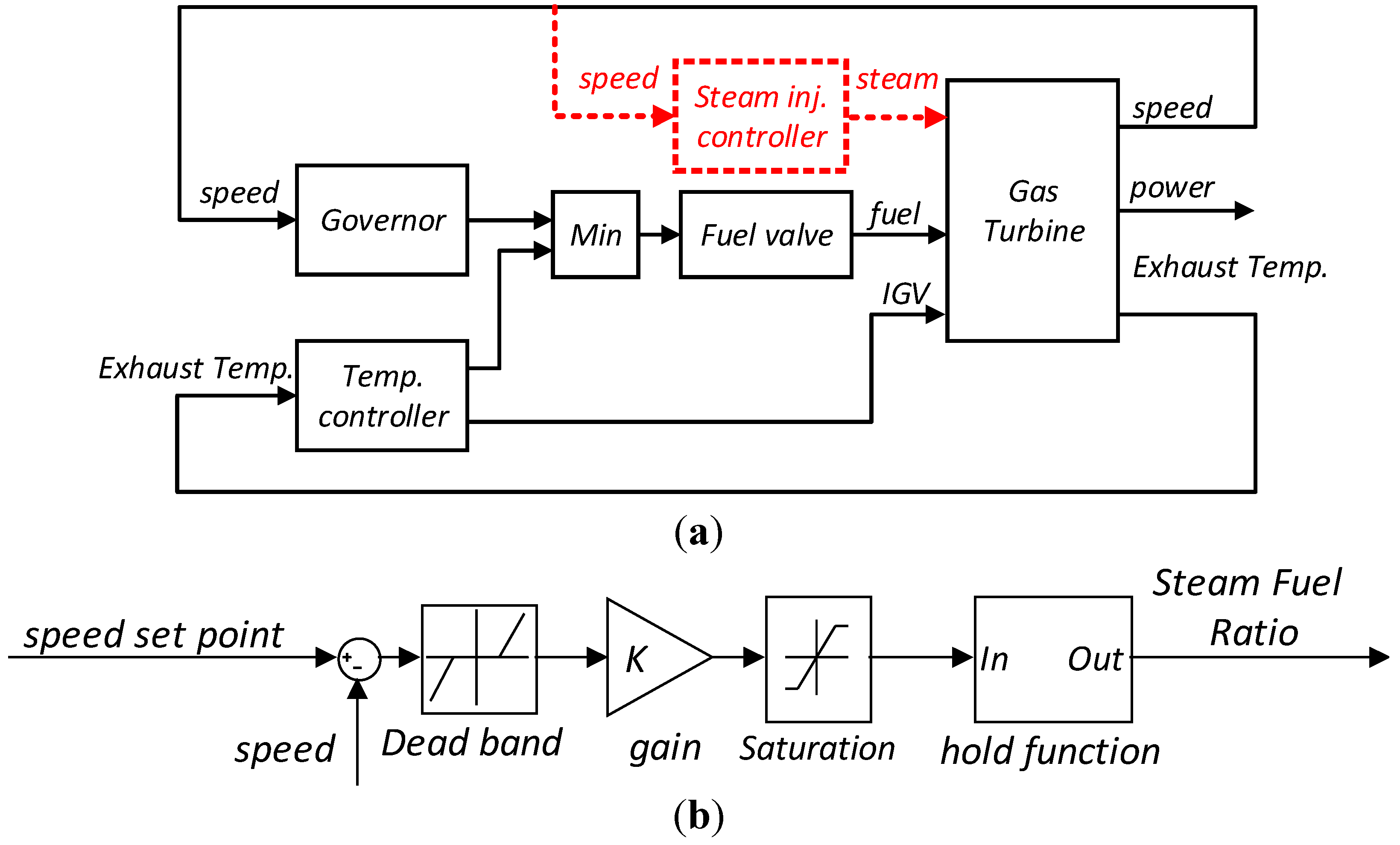
To implement the proposed solution, a new loop is added for steam injection to the gas turbine original control system. This loop which is shown in
Figure 3 includes following elements.
Figure 3.
(a) New control loop configuration; and (b) steam injection controller details.
Figure 3.
(a) New control loop configuration; and (b) steam injection controller details.
3.1. Dead Band
The gas turbine original control system can recover small frequency dips, so it is not necessary to use steam injection. Also, as stated in the previous section good water quality is required for steam injection. Producing such a high quality steam is quite expensive and using steam injection for small frequency dips will be a waste of resources.
3.2. Saturation
The controller should act as fast as possible to have successful frequency recovery, otherwise the situation will become worse and more difficult to handle. Therefore, a high gain controller is used in this loop. But large amount of steam injection might push the engine into the unstable working regions, so to restrict the amount of steam that can be injected into the gas turbine a saturation element is added to this loop.
3.3. Hold Function
With regular control algorithm, the amount of injected steam will be proportional to the gas turbine speed deviation from its nominal value. So the controller will cut off the steam injection as soon as it recovers the frequency. If, however, the steam injection continues for a while and decreases with a slow rate, it can provide the required time for the governor and IGVs to move to the new operating condition more smoothly. This would reduce the temperature gradients in the engine component and as a result, extend the service time of these components. So the amount of injected steam should be increased as fast as possible and reduces in a slow rate after frequency recovery. The hold function which is shown in
Figure 4a is designed for this purpose. The time that controller should continue steam injection after frequency recovery can be adjusted easily by tuning the lower limit of the saturation block. The behavior of the developed hold function to a sample input is shown in
Figure 4b for different hold times.
Figure 4.
(a) Hold function; and (b) the response of the hold function to a sample function (gain = 100, upper limit = 1000).
Figure 4.
(a) Hold function; and (b) the response of the hold function to a sample function (gain = 100, upper limit = 1000).
4. Surge Margin
Compressor surge is associated with a sudden drop in delivery pressure, and violent aerodynamic pulsation which is transmitted throughout the whole machine [
20] and it should be avoided to protect the engine from damage. It happens when the delivery pressure of the compressor is lower than the downstream pressure. In single-shaft engines used for power generation, the combustor pressure is proportional to the engine load, so steam injection and over fueling which are increasing the output power will lead to pressure rise in the combustion chamber as well. Consequently, large amount of steam injection or overfueling may cause the gas turbine compressor to surge.
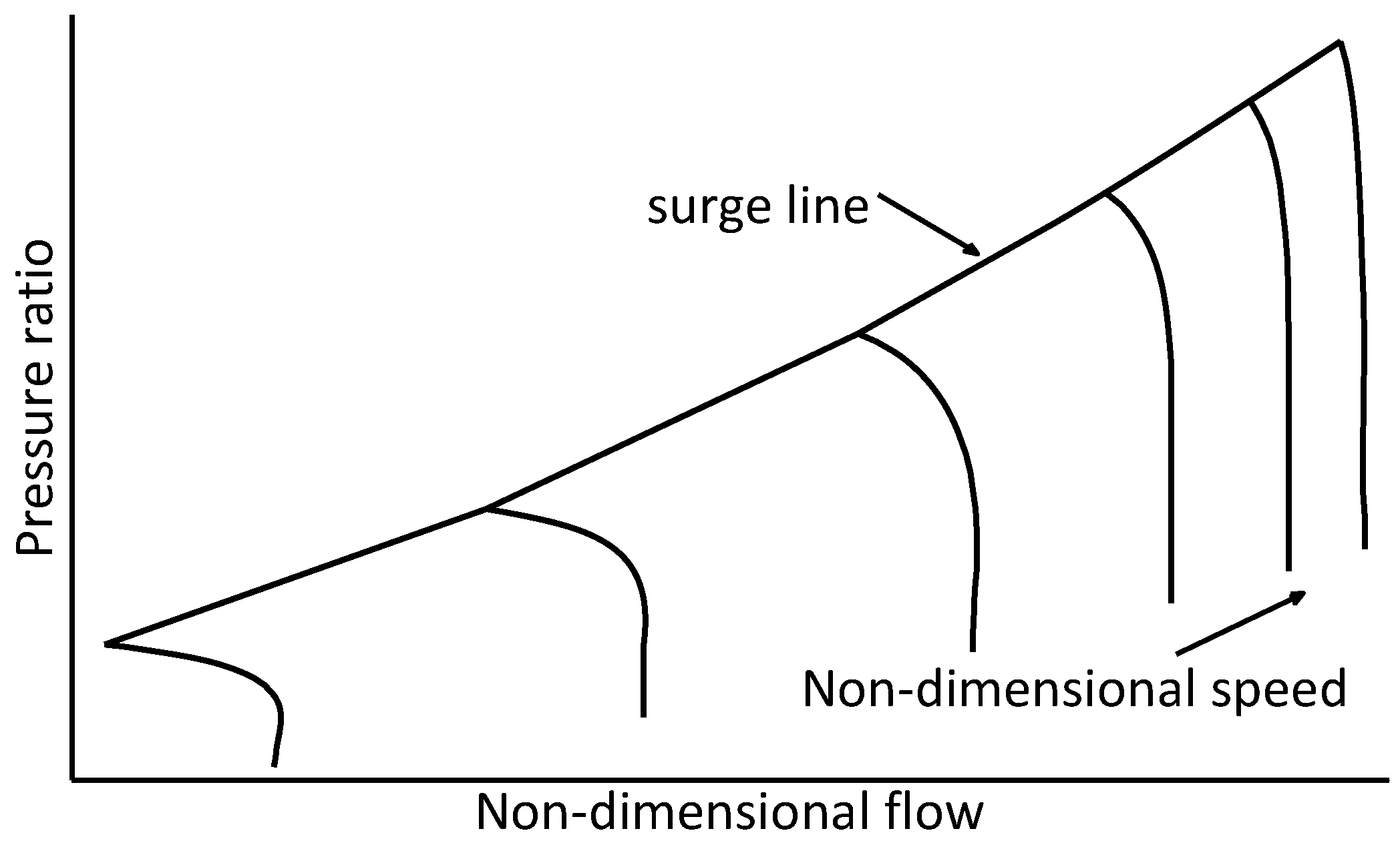
In the compressor characteristic map, the surge region is specified with a surge line (
Figure 5). The compressor should operate within a safe distance from the surge line because of different reasons such as production tolerances, engine aging, and transient allowance,
etc. The parameter for quantifying this distance is called surge margin and it denotes the relative distance of working point from the surge line. The surge margin is defined as:
where
Pr stands for compressor pressure ratio. The normal surge margin which is considered for transient maneuvers is about 10%–15% [
5]. The important point that should be noted here is that, the surge margin depends on the compressor speed and it decreases by speed reduction [
4].
Figure 5.
Schematic compressor map.
Figure 5.
Schematic compressor map.
To compare the effect of steam injection verses overfueling on the compressor surge margin reduction, some simulations has been done and the results are summarized in
Table 1. In these simulations, the output power of the gas turbine is kept constant with different amount of steam injection. As it can be seen, by increasing the amount of injected steam, the compressor pressure ratio will be increased slightly and at same time the firing temperature will be lower. So for the same output power, steam injection will reduce the surge margin more than fuel.
Table 1.
Dry engine vs. steam injected engine parameters.
Table 1.
Dry engine vs. steam injected engine parameters.
| Engine load [MW] | 161 | 161 | 161 |
|---|
| steam-fuel ratio(SFR) | 0 | 1 | 2 |
| pressure ratio | 11.66 | 11.78 | 11.91 |
| Turbine inlet temperature (TIT) [k] | 1333 | 1311 | 1305 |
5. Simulation Results
A 160 MW heavy-duty gas turbine was studied in order to investigate the performance of the proposed control algorithm. The complete physical model for a dry engine is developed based on the heat and mass balance for different gas turbine components and using the characteristic maps for compressor and turbine. This physical model and the required control system are simulated in Matlab/Simulink environment. The performance of the developed model for dry engine is validated by real data from an operating plant. After dry engine validation, the steam injection is also considered in the physical model and finally, the proposed control algorithm is added to the developed model. The performance of the proposed control system is compared with the regular gas turbine control algorithm in two different scenarios.
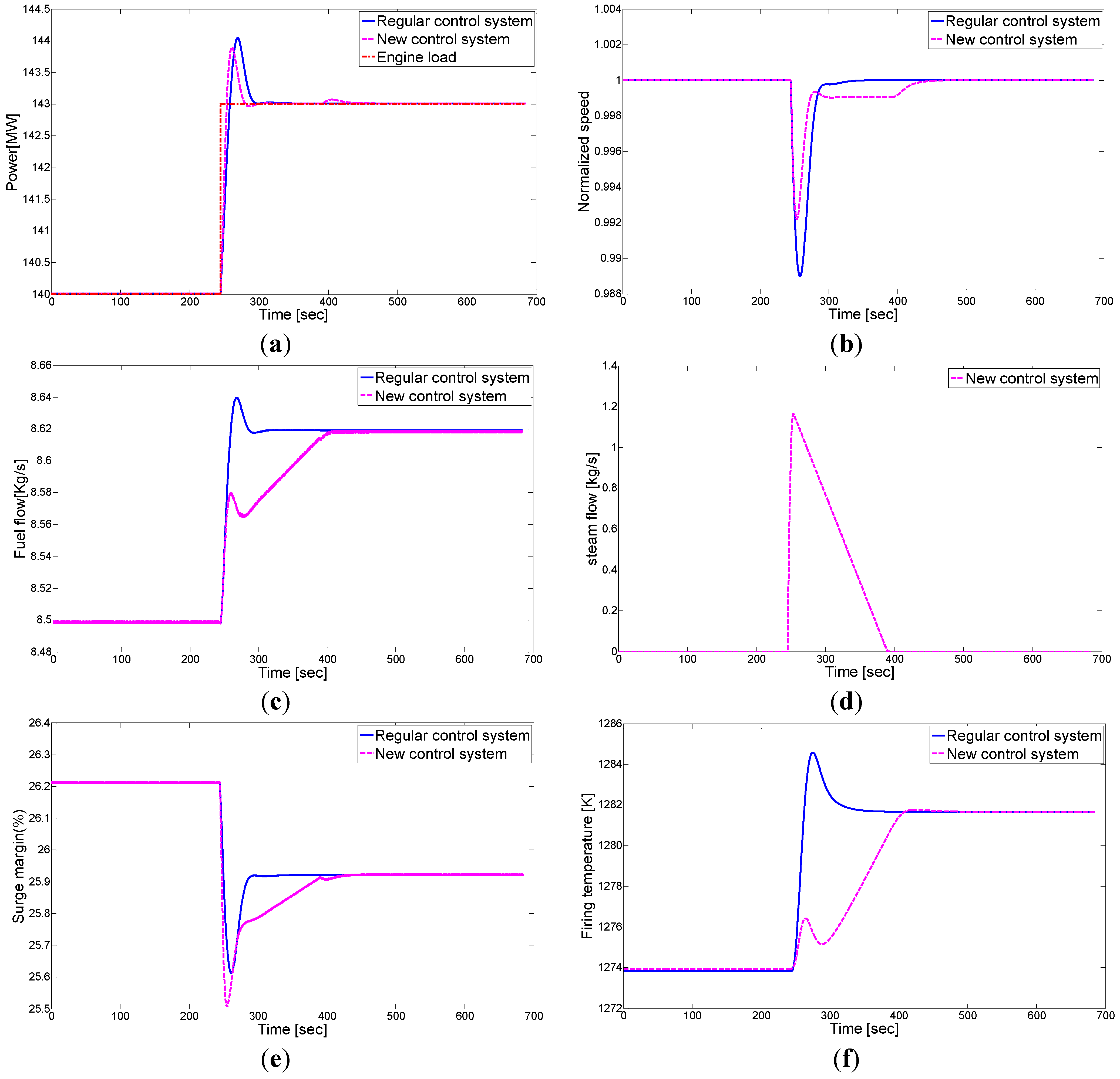
In first simulation, the performance of both control systems is compared to a step change in gas turbine load when the gas turbine is running in the island mode. The simulation results and important engine variables are shown in
Figure 6. The results are summarized in the following paragraphs.
Figure 6.
Comparison between the new control system and regular gas turbine control system in island mode-steam injection controller setting (dead band upper limit and lower limit = 0.001, −∞, gain = 20, saturation limit = 0.3): (a) power; (b) speed; (c) fuel flow; (d) steam flow; (e) surge margin; and (f) firing temperature.
The response of the new control system to the step change load is faster than the original control algorithm. This results in a smaller frequency drop for the new controller and the peak power of the new controller is also smaller than the original control algorithm. On the other hand, the new control system has a small speed deviation for a short period of time after frequency recovery. This deviation is related to the hold function in new controller structure. The hold function reduces the amount of steam injection slowly after the frequency recovery and the governor tries to keeps the output power constant by increasing the fuel flow. Since the governor works with the speed deviation, there should be a small error, therefore, the governor can replace the decrease in steam injection with the increase in fuel flow.
As stated in previous sections, the steam injection can reduce the compressor surge margin and it affects the surge margin more than the engine overfueling. Moreover, the surge margin is also decreased by a speed reduction. Consequently, although steam injection reduces the surge margin, it will result in a smaller frequency dip. Therefore, the compressor surge margin is only slightly affected by the new control algorithm.
A small amount of steam injection can enhance the gas turbine performance. The maximum steam mass flow rate is 1.2 kg/s and the total amount of injected steam during this transient maneuver is about 86.5 kg. Also, application of the steam during the transient maneuvers reduces the temperature gradient in firing temperature and consequently in engine components, which will increase the service life of the engine components.
The second simulation investigates the maximum allowable change load for these control algorithms in island mode. There are two main restrictions that limit the allowable change load that the gas turbine can have. Firstly, the temperature controller, which reduces the fuel flow when the firing temperature reaches to its safety limits, makes it impossible to load the gas turbine further. This limitation usually plays a role in high engine loads where the engine already has a high firing temperature, and thus it will be activated with a small amount of overfueling. The second limitation is the safety limit for surge margin which plays the main role at lower loads. In these loads the firing temperature is relatively low and this means that there is a large gap before the temperature controller is activated. Consequently, the engine can be overfueled more and this large overfueling will push the engine towards the surge region before the temperature controller is activated. Considering both of these limitations the performance of the proposed control algorithm (for different amount of maximum allowable steam injection)
vs. the original control algorithm is presented in
Figure 7.
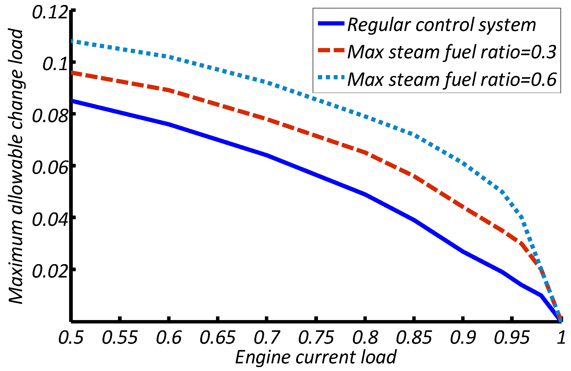
Figure 7.
Maximum allowable change load in different load for the proposed control algorithm vs. the regular control algorithm when the gas turbine is running in island mode.
Figure 7.
Maximum allowable change load in different load for the proposed control algorithm vs. the regular control algorithm when the gas turbine is running in island mode.
It can be seen that engine allowable change load will be decreased when the engine gets closer to its full load condition. Additionally, in high engine loads, where the temperature controller limits the maximum allowable change load, the steam injection can enhance the gas turbine performance. This is because steam injection will reduce the firing temperature and therefore, the temperature controller will not be activated very quickly. Also, steam injection augments the output power without increasing the firing temperature. On the other hand, at low engine loads, the surge margin limits the allowable change load. Although steam injection reduces the compressor surge margin, but when the control system takes advantage of steam injection, the engine can respond much faster to sudden change loads. Consequently, the engine will experience a smaller frequency drop and the compressor surge margin decrease will be less than the regular control algorithm because of speed reduction. This effect not only compensates the surge margin reduction because of steam injection, but also overrides that effect in large change loads which will lead to large frequency drops. Therefore, the engine will be able to manage higher change loads.
Another important issue in gas turbine performance is the engine maximum loading rate near full load condition. Faster engine loading means more overfueling and since the firing temperature is high near full load condition, more overfueling will activate the temperature controller and limits the gas turbine loading rate. Therefore, most of the gas turbine manufactures decrease the engine loading rate near full load condition. The proposed control algorithm can enhance the maximum engine loading rate near full load condition as well. For example, for the sample engine, the maximum loading rate is 4.6 MW/min for regular control algorithm and it can be increased to 8 MW/min and 10.5 MW/min with the proposed control algorithm for maximum steam fuel ratio of 0.3 and 0.6, respectively.
These simulation results show that the proposed control algorithm can improve the performance of the gas turbine during the frequency dips and transient maneuvers. The proposed control algorithm will be more effective near full load condition where the regular control algorithm is not capable to manage even small frequency dips.


