1. Introduction
Classical thermodynamics, a field that concerns thermal equilibrium problems, involves the performance indices of a time-invariant system. These include, for example, efficiency, delivered power, and similar factors, for a quasi-static thermodynamic process. As an extension and generalization of classical thermodynamics, the finite-time thermodynamics, which takes time into account, can be used to describe the dynamics of energy and entropy flow in a non-equilibrium system. Taking into consideration time-invariant quantities, such as power, refrigeration rate, power density, entropy production rate, and others, finite-time thermodynamics is effectively adopted to optimize the performance of practical systems. It has been successfully utilized in a wide range of disciplines, an important of which is the optimization of practical performance of thermodynamic cycles, such as the Carnot cycle, the Otto cycle, the Diesel cycle, the Brayton cycle, the Stirling cycle, and others.
In 1957, Novikov [
1] was the first pioneer in the field of finite-time thermodynamics, and Curzon and Ahlborn [
2] proposed a more adequate thermal efficiency analysis for practical thermal processes, where the upper bound on the thermal efficiency was modified accordingly by considering the loss due to thermal resistance. Ondrechen
et al. [
3] performed a thermal analysis of a heat source of finite extent. In 1985, DeVos [
4] extended the scope of finite-time thermodynamics using various heat transfer laws.
In 1991, Angulo-Brown [
5] introduced an ecological optimization criterion as an objective function to optimize the performance of a heat engine, taking into account the maximum output power and the rate of production of entropy. [
5] showed that the production rate of entropy is greatly reduced by costing part of output power, when the optimum thermal efficiency is approximated as the average of the respective efficiency suggested by Carnot and that suggested by Curzon and Ahlborn [
2]. In 1991, Ibrahim
et al. [
6] considered irreversible parameters - the isentropic ratio of the isothermal processes and thus optimized the Carnot cycle by a more practical manner. Based on the assumption that the temperature of a gas varies linearly with the temperature of the surface of the wall of the cylinder that contains it, Klein [
7] proposed the net output power and an optimized compression ratio for designing an engine with the greatest possible power output. Wu and Kiang [
8] performed a finite heat transfer analysis to investigate the effects of a nonisentropic compression process, expansion process, turbine efficiency and compressor efficiency and a heat exchanger on the output power optimization. In 1993, Chen and Yan [
9] evaluated the maximum output power with the consideration of the irreversible factors, which are heat leakage, finite heat transfer between the heat reservoir and the heat engine in the compression and expansion processes. In 1995, Ait-Ali [
10] considered the range of operating temperatures to optimize the output power of an endoreversible Carnot engine. Angulo-Brown
et al. [
11] used the Clausius inequality to modify the parameters as well as a linear time-temperature relationship, and took into account the power loss, to obtain analytic solutions for both the output power and the thermal efficiency. In 1998, Chen
et al. [
12] noted that in an Atkinson cycle, the thermal efficiency at the point of maximum power density is always better than that at the point of maximum power. Chen
et al. [
13] also investigated the effect of heat transfer on an Otto cycle. In 1999, [
14] proposed a generalized Otto cycle and quantified the degree of irreversibility in a study of performance optimization in various heat transfer modes. Lin
et al. [
15] also represented an effective method for improving heat engine performance in practical operation for a dual combustion cycle using the finite-time thermodynamics approach. In 2004, Hou [
16] examined the effect of heat transfer on a dual combustion cycle. Zhou
et al. [
17] studied the effect of a generalized heat transfer law on the optimization of power output of a generalized Carnot engine with internal and external irreversibility. In 2007, Hou [
18] proved that the expansion ratio in an Atkinson cycle exceeds the compressive ratio in an Otto cycle. In 2009, Lu
et al. [
19] applied the energy equilibrium equation for a collecting plate to optimize a solar power generating system, in which the efficiency of the light collection unit of the solar concentrator was optimized at such operating temperature corresponding to the working fluid temperature.
The finite-time thermodynamics, as its name indicates, applies in many range of fields, whenever heat transfer occurs in a device or a system of finite extent or within a limited period. Under some suitable assumptions, this work proposes a constrained model to optimize the performance of a practical heat engines with irreversible thermodynamic process. In finite-time thermodynamics, the optimization of performance indices involves the optimization of an overall system on the assumption of irreversibility. Comparing with the classical thermodynamics, it is more adequate when applied to practical applications, and is useful in studies of the best use of energy.
This paper investigates the maximum power output design problem for a solar powered Stirling engine, where the thermal efficiency and solar collector temperature are considered as the design parameters. The heat transfer between the solar collector to the engine and the surroundings is studied such that the result can provide an adequate prediction for overall system thermal efficiency in practice.
2. Maximum Power Analysis of Stirling Engine with Solar Collector
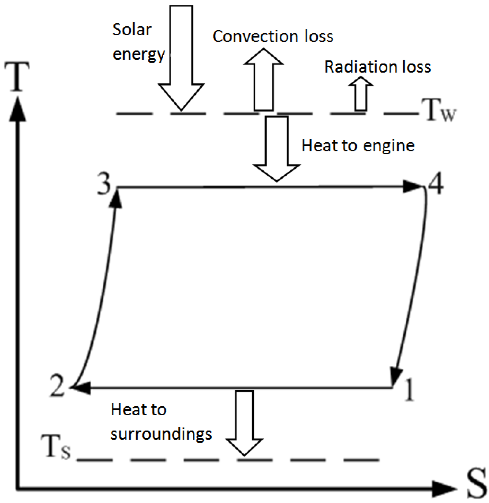
The thermal model for a Stirling engine with solar collector which mainly consists of a spherical reflector and an absorber that acts as a heat source is shown in
Figure 1 [
20]. A collector, which is connected to an expansion chamber of the heat engine, is directly heated, and the heat is released to the ambient by radiation and natural convection as the surface temperature of the collector is increased.
Figure 1.
Heat flows involved in a Stirling engine with solar collector.
Figure 1.
Heat flows involved in a Stirling engine with solar collector.
Considering the heat loss on the collector surface and from the law of conservation of energy, it yields:
The heat absorption efficiency on the collector surface is defined as:
In this model, heat is transferred to the expansion chamber, where a high conductive coefficient and extremely thin surface of the collector is applied such that the temperature on the interior surface of the expansion chamber is almost equal to that in the collector. The working fluid is considered as the ideal gas and the heat transfer process follows Newton’s linear heat transfer law. In each cycle,
Qin is the heat absorbed by the working fluid, and
Qout is the heat released to the ambient. The temperature of the corrector is denoted as
Tw and the ambient temperature is denoted as
Ts. The heat from the collector to the Stirling engine satisfies:
and the heat released by the Stirling engine to the ambient is given by:
where
t12 and
t34 are the times required for engine heat rejection and engine heat accumulation, respectively.
T1 and
T3 are the temperature of the working fluid in the isothermal heat rejection and addition process, respectively.
In the isothermal and endothermic process, the entropy terms in the thermodynamic relation yield:
The ideal gas equation is:
Substituting Equation (6) into Equation (5) yields:
Integrating Equation (7) over states 3 and 4 yields:
Substituting Equation (9) into Equation (8) yields:
In each cycle, the incremental entropy in the working fluid inside a Stirling engine is given by:
Since entropy behaves analogously to heat, it is independent of the integration path itself. Therefore, the net change in entropy between the initial and final states of a complete cycle is identically zero:
From the Second Law of thermodynamics:
The Clausius inequality yields:
From Equations (12) to (14):
Now, let:
where
ϕ is an irreversible property of a Stirling engine, such as thermal resistance, friction, heat loss. Consistent with the second law of thermodynamics, such irreversible factors, which cannot be ignored, bring about an increase in entropy in each cycle. Given an identical amount of heat transfer
Qin, for an endoreversible heat engine
ϕ > 1,
Qout is expressed as:
Relating Equation (16) to (17) yields:
In a Stirling engine, the heat that is released to low-temperature thermal storage (cold chamber) in a reversible isothermal process is:
Back-substituting Equation (19) into Equation (18) yields:
Let compressive ratio
rv be defined as:
Equating Equation (3) with Equation (10) and substituting Equation (21) into Equation (3) yields:
The endothermic time of the heat engine is given by:
Equating Equation (4) with Equation (20) and substituting Equation (21) into Equation (4) yields:
The time for which the heat engine is exothermic is:
Suppose that in the heat regenerating process, the temperature of the working fluid,
Tfluid, varies linearly with time:
where
K1 > 0, which is the average rate of change of temperature, and is independent of time but dependent on the material of the heat regenerator, is called the heat regenerative time coefficient: a positive or negative sign shows that the temperature increases or decreases with time, respectively.
The duration of the heat regenerative process from state 2 to state 3 is:
Similarly, that of the heat regenerative process from state 4 to state 1 is:
Accordingly, time for a complete Stirling cycle is represented as:
Substituting Equations (23), (25), (27) and (28) into Equation (29) yields:
In each cycle, the effective energy in a collector is:
Substituting Equations (10), (21) and (30) into Equation (31) yields the total amount of heat applied to a Stirling engine in each cycle, which is:
The thermal efficiency of a heat engine is defined as:
Substituting
and
into Equation (32) yields:
The heat that is released to the ambient in a Stirling cycle is given by:
Substituting Equations (20), (30) and (33) into Equation (35) yield:
The output power that is provided by a Stirling engine in a Stirling cycle is:
From the collector temperature and the thermal efficiency, the amount of heat that is applied to the collector is determined using Equation (11); then, Equation (34) is solved for the endothermic temperature of the heat engine, which is expressed in a quadratic form as:
where:
In the above three parameters, the parameter
s is defined as:
From Equation (33), the rejection temperature of the heat engine is:
Given the collector temperature, the heat transferred from the collector to the heat engine is determined. Partial differentiation of Equation (34) with respect to endothermic temperature yields the optimized endothermic temperature:
Back-substituting Equation (41) into Equation (34) yields the amount of heat applied at the optimal endothermic temperature:
3. Results and Discussion
For a given solar intensity, the relation between the thermal efficiency of a Stirling engine and the collector temperature are studied in this section. Thermal efficiency of an engine can be improved by either increasingg
T3 of the isothermal heat addition process, or reducing
T1 of the isothermal heat rejection process. In general, the heat rejection temperature will not fall below the ambient temperature, so the intended thermal efficiency can only be improved by elevating
T3. Since the collector receives limited energy for a given solar intensity and it loses heat to the surroundings by both radiation and convection, a temperature upper bound will exist for the collector as well as the
T3 of the thermal process. Also, the temperature difference between them will determine the heat been accumulated by the engine from the collector. In this study, a solar powered Stirling engine with the solar intensity = 4000 W/m
2 is considered with system parameters listed in
Table 1.
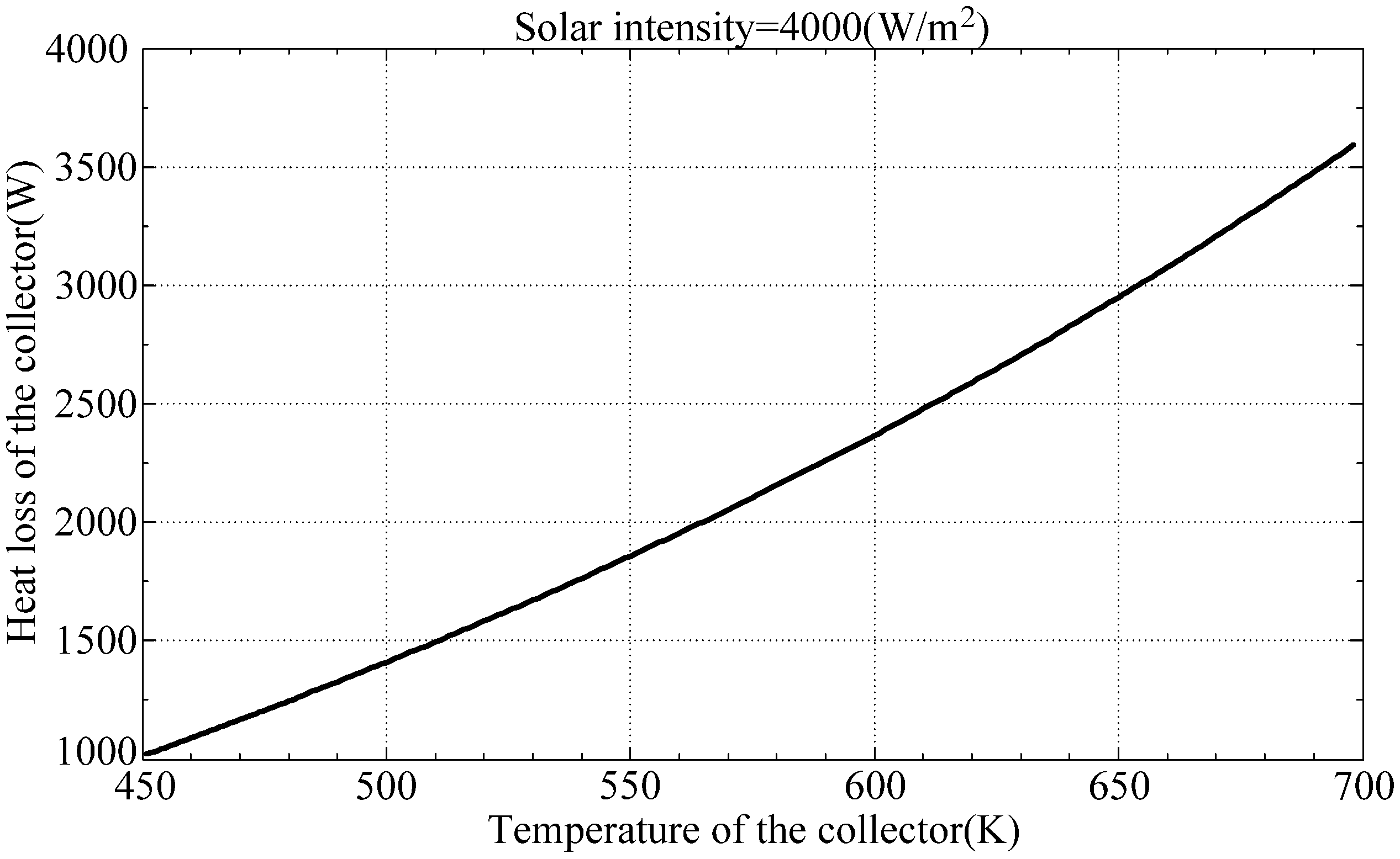
Equation (1) is used to determine the heat loss from the collector to the surroundings which can be used to determine a reasonable heat available for the engine.
Figure 2 reveals the heat loss by the collector with respect to collector temperature. When the collector temperature exceeds 698 K, the heat loss from the collector exceeds the amount of solar power can possibly been accumulated.
Table 1.
System parameters for optimization study.
Table 1.
System parameters for optimization study.
| System Parameters | Values |
|---|
| Solar intensity | Isun = 4000 W/m2 |
| The upper bound of thermal efficiency | 0.57 |
| The temperature of collector | 450–698 K |
| The coefficient of convection in the expansion chamber | hf = 90 W/(m2·K) |
| The coefficient of natural convection | hn = 5 W/(m2·K) |
| The product of heat transfer coefficient and heat transfer area between cold-end chamber to the surroundings | α1 = 50 W/K |
| Surface radiation emission rate | ε = 0.12 |
| Boltzmann constant | σ = 5.67 × 10⁻⁸ W/(m2·K4) |
| Collector wall absorption rate | ω = 0.9 |
| Degree of irreversible factor in heat engine | ϕ = 1 |
| Ambient temperature | Ts = 293 K |
| Collector area | Ac = 1 m2 |
Figure 2.
Heat loss from collector to the surroundings.
Figure 2.
Heat loss from collector to the surroundings.
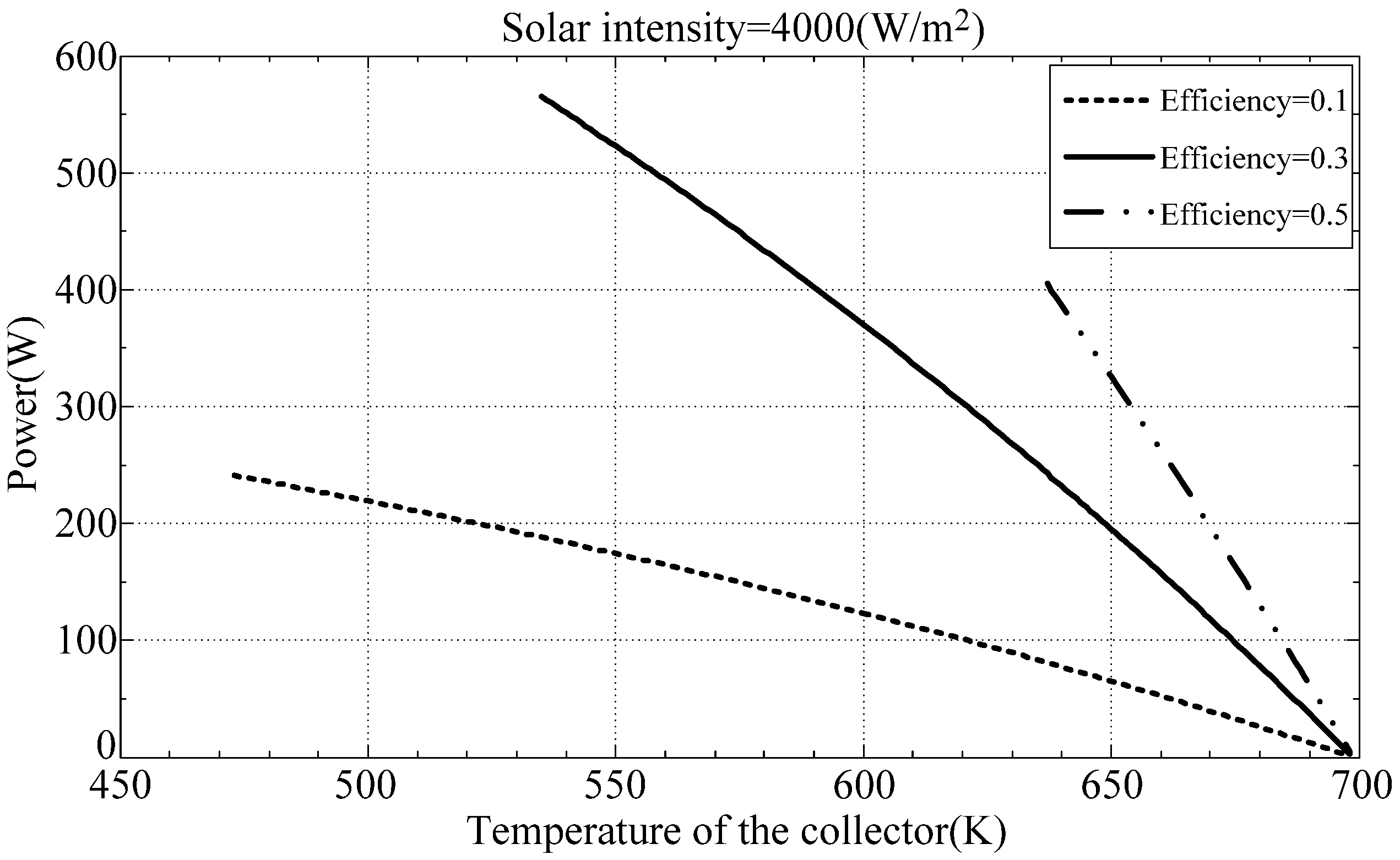
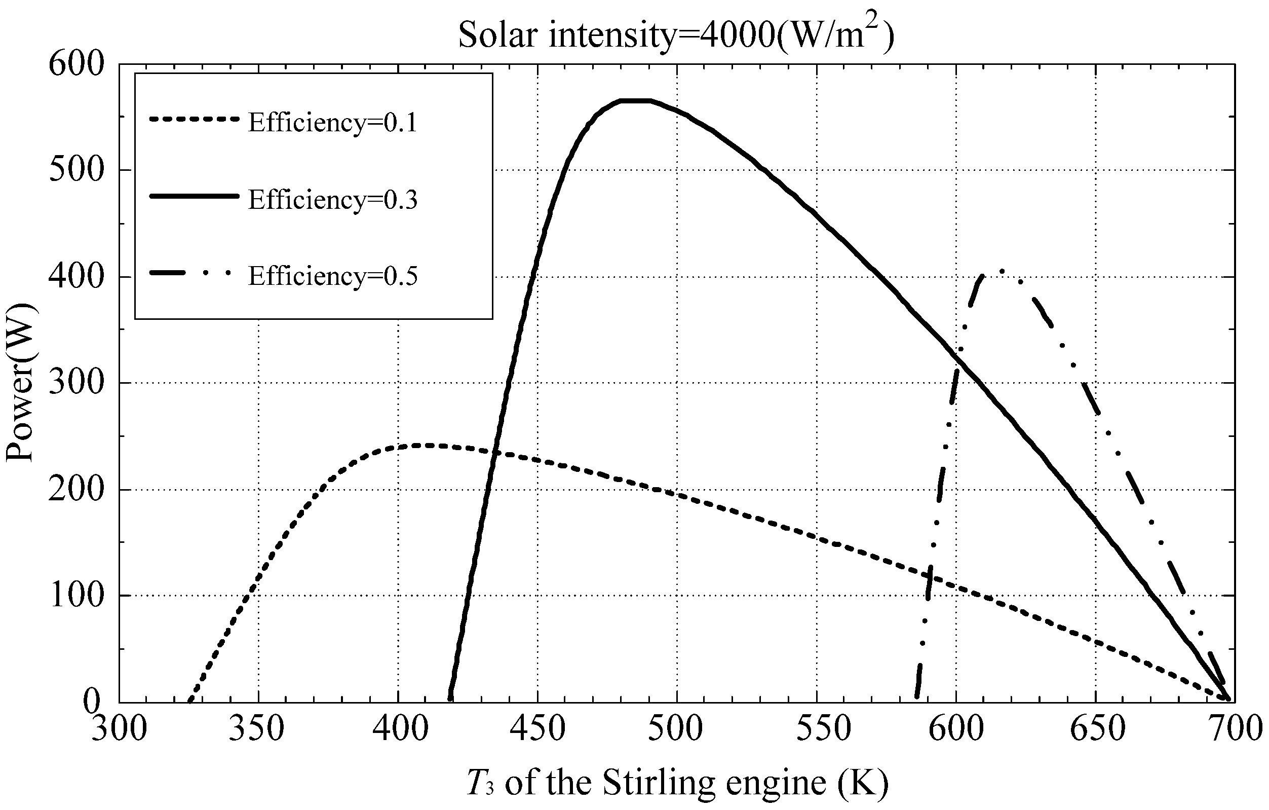
Figure 3 plots the output power as a function of the collector temperature at thermal efficiencies of 0.1, 0.3 and 0.5.
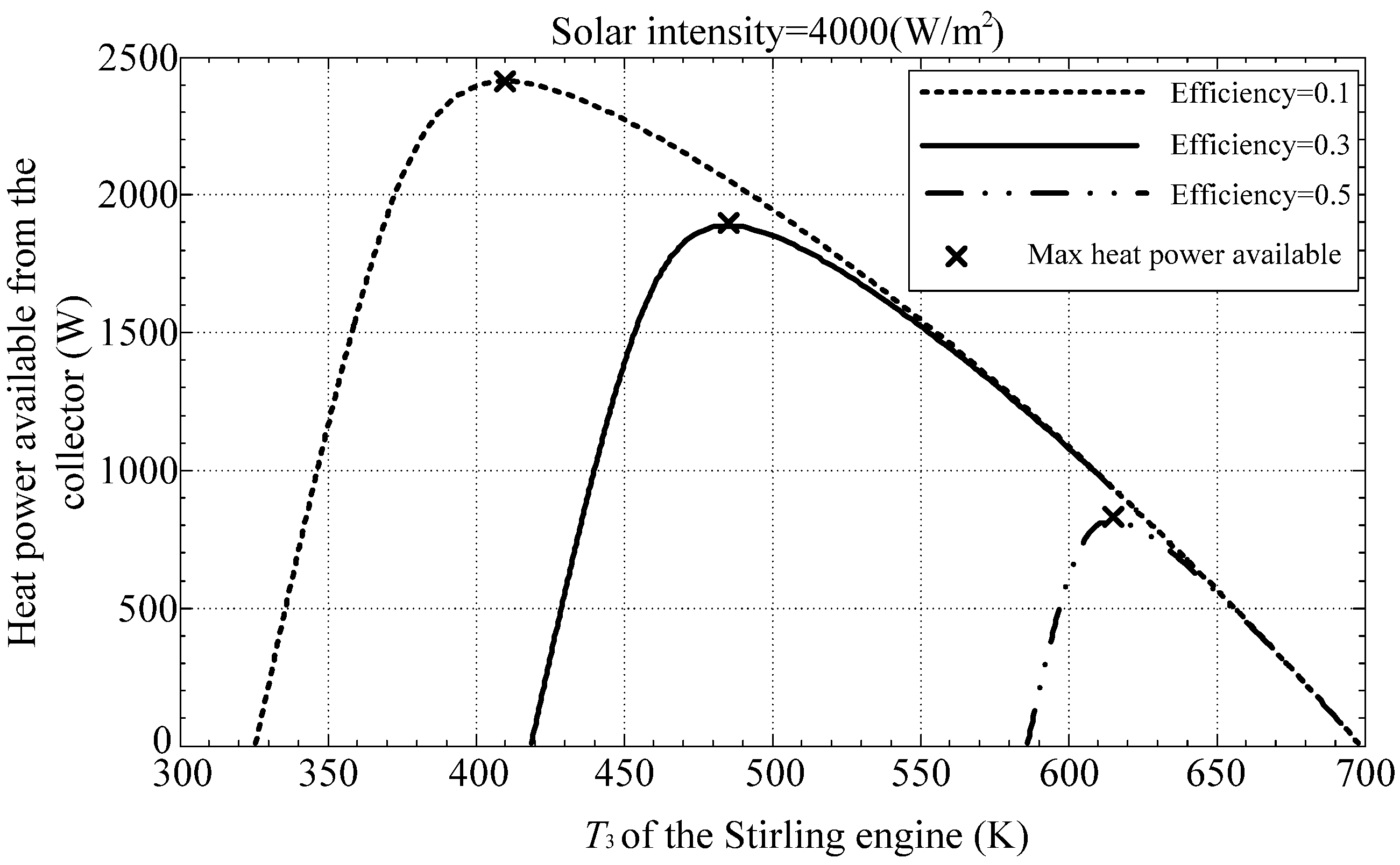
Figure 4 illustrates available heat for the engine for different isothermal heat addition process temperature
T3. The maximum power available according to the optimal hot-end temperature determined by Equation (41) is also indicated in
Figure 4. Accordingly, the output power generated by the engine is shown in
Figure 5.
Figure 3,
Figure 4 and
Figure 5 reveal that a higher
T3 will result higher thermal efficiency; however, it will also reduce the heat power been accumulated from the collector. Therefore, the maximum power output of the engine requires a trade-off between thermal efficiency and isothermal heat addition process temperature of the thermal process.
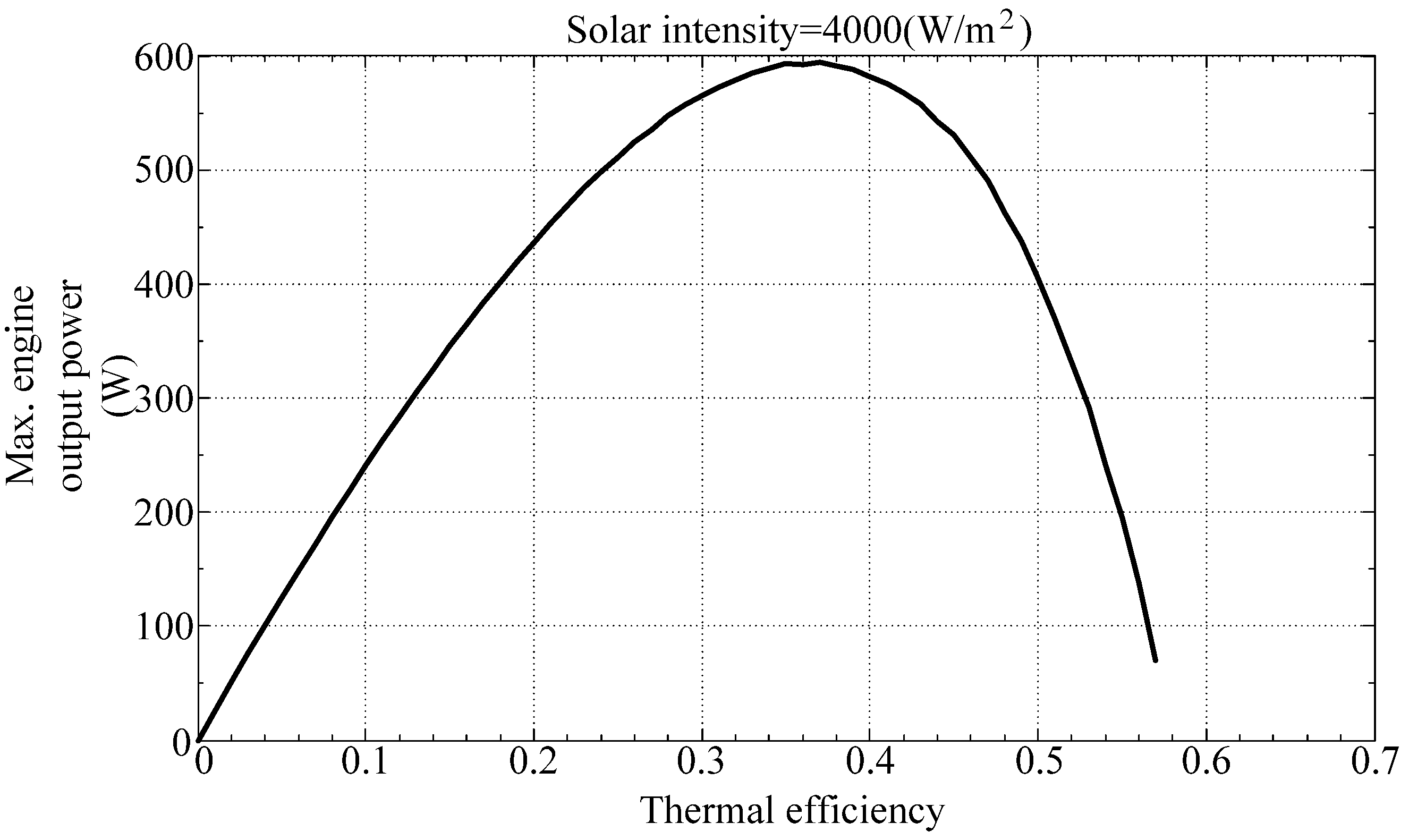
Figure 6 and
Figure 7 illustrate the maximum output power of the engine with respect to thermal efficiency and collector temperature, respectively. They show that the solar powered Stirling engine will generate maximum power at a thermal efficiency of between 0.3 and 0.4 and a collector temperature of between 550 K and 600 K.
Figure 3.
Engine output power.
Figure 3.
Engine output power.
Figure 4.
Available power from the collector.
Figure 4.
Available power from the collector.
Figure 5.
Engine output power.
Figure 5.
Engine output power.
Figure 6.
Maximum engine output power with respect to thermal efficiency.
Figure 6.
Maximum engine output power with respect to thermal efficiency.
Figure 7.
Maximum engine output power with respect to collector temperature.
Figure 7.
Maximum engine output power with respect to collector temperature.
Table 2.
System parameters for maximum output power.
Table 2.
System parameters for maximum output power.
| System Parameters | Values |
|---|
| Solar intensity (Psolar) | 4000 W/m2 |
| Collector wall absorption rate | 0.9 |
| Power accumulated by collector | 3600 W/m2 |
| Collector temperature | 560.4 K |
| Radiation heat loss | 621 W/m2 |
| Convection heat loss | 1337 W/m2 |
| Collector efficiency | 0.41 |
| The input power of heat engine | 1642 W |
| Thermal efficiency | 0.363 |
| The temperature of the working fluid in the isothermal heat addition process (T3) | 517.4 K |
| The temperature of the working fluid in the isothermal heat rejection process (T1) | 329.7 K |
| The output heat of heat engine | 1047 W |
| The power generated by the heat engine (PStirling) | 596 W |
| The total power loss of the system | 3404 W/m2 |
| Overall system thermal efficiency (PStirling/Psolar) | 0.149 |
Finally, the optimum design parameters are determined using a genetic algorithm. The maximum output power of a Stirling engine and the corresponding parameters are determined using the Matlab Toolbox Genetic Algorithm Toolbox, with the output power as an objective function, and the thermal efficiency and the collector temperature as optimized parameters. As shown in
Table 2, the simulation yields a maximum output power of 596 W at a thermal efficiency of 0.363 and a collector temperature of 560.4 K, which also confirms the expecting result from
Figure 6 and
Figure 7.


