Article

Performance Analysis and Working Fluid Selection of a Supercritical Organic Rankine Cycle for Low Grade Waste Heat Recovery

Key Laboratory of Low-grade Energy Utilization Technologies and Systems of Ministry of Education, College of Power Engineering, Chongqing University, Chongqing 400030, China
*
Author to whom correspondence should be addressed.
Energies 2012, 5(9), 3233-3247; https://doi.org/10.3390/en5093233
Submission received: 10 July 2012 / Revised: 15 August 2012 / Accepted: 23 August 2012 / Published: 30 August 2012
(This article belongs to the Special Issue Waste to Energy Technologies)

Abstract

:
The performance analysis of a supercritical organic Rankine cycle system driven by exhaust heat using 18 organic working fluids is presented. Several parameters, such as the net power output, exergy efficiency, expander size parameter (SP), and heat exchanger requirement of evaporator and the condenser, were used to evaluate the performance of this recovery cycle and screen the working fluids. The results reveal that in most cases, raising the expander inlet temperature is helpful to improve the net power output and the exergy efficiency. However, the effect of the expander inlet pressure on those parameters is related to the expander inlet temperature and working fluid used. Either lower expander inlet temperature and pressure, or higher expander inlet temperature and pressure, generally makes the net power output more. Lower expander inlet temperature results in larger total heat transfer requirement and expander size. According to the screening criteria of both the higher output and the lower investment, the following working fluids for the supercritical ORC system are recommended: R152a and R143a.

1. Introduction

Over the past years, with the increasing consumption of fossil fuels, more and more low-grade industrial processes are producing a great amount of waste heat. Being discharged into the environment, this exhaust energy could cause serious heat pollution. However, if made good use of, this exhaust energy could reduce fossil fuel consumption. To recover and utilize this type of energy, the organic Rankine cycle (ORC) system was proposed. The ORC is similar to the steam Rankine cycle, except for using organic working fluids with low boiling points.
Besides the ORC, researchers have proposed various thermodynamic cycles, such as Kalina cycle, Goswami cycle, and trilateral flash cycle, to convert this low-grade heat sources into electricity. Although there is more power output for the same heat input with Kalina cycles compared to ORCs, the ORC syetem is much less complex and needs less maintenance [1,2]. A variety of pure organic fluids have been studied for use in ORC systems, such as HCFC123, HFC-245fa, HFC-245ca, isobutene [3,4,5,6,7], n-pentane [8] and aromatic hydrocarbons [9]. Tamamoto et al. [3] found that R123 could give higher turbine power than water in ORC system. Wei et al. [7] optimized the ORC system performance using R245fa as working fluid. Saleh et al. [10] screened 31 pure working fluids for ORCs based on the BACKONE equation of state. Liu et al. [11] investigated the effects of various working fluids on the thermal efficiency and the total heat recovery efficiency. Hung [12,13] explored working fluids for ORC system, including benzene, ammonia, toluene, p-xylene, R113, R11, R12, R134a and R123. They compared the efficiencies of these working fluids, and found that R113 and R123 gave better performance. Lee et al. [14] proposed a systematic algorithm of parameters analysis on ORC. It is found that the recovering low-pressure waste steam by this ORC provides a high potential for moderate capacity plants. Wang et al. [15] presented a multi-objective optimization model for the subcritical ORC. They indicated that R123 is the best choice for the temperature ranges from 373 K to 453 K and R141b is the optimal working fluid for temperatures higher than 453 K.
Because the organic fluids have lower critical temperatures and pressures, they can be compressed directly to their supercritical pressures and heated to their supercritical state before expansion. Supercritical ORC could achieve a better thermal match with the heat source [8,16]. The heating process of a supercritical ORC does not pass through a two-phase region like a subcritical ORC, resulting in a better thermal match in the evaporator with less irreversibility [10]. Chen et al. [16] compared the system performance between a supercritical Rankine cycle using CO2 as working fluid and a subcritical ORC using R123 as working fluid. Their findings showed that a CO2 supercritical ORC power cycle has higher system efficiency when taking the behavior of the heat source and the heat transfer between heat source and working fluid in the main heat exchanger into account. This is mainly due to better temperature glide matching between heat source and working fluid. Zhang et al. [17,18,19] studied the supercritical Rankine cycle using CO2 as a working fluid. Their results showed that the cycle has a power generation efficiency of somewhat above 20.0% and heat recovery efficiency of 68.0%, respectively. Karellas et al. [20] studied the supercritical ORC using isobutene, propane, propylene, difluoromethane and R-245fa as working fluids. It was found that supercritical fluids could maximize the efficiency of the system. Although the supercritical Rankine cycle can obtain a better thermal match than the subcritical ORC, the supercritical ORC normally needs high pressure, which may lead to difficulties in operation and safety concerns [8]. Schuster et al. [21] studied the optimization potential of supercritical ORC. Various working fluids, such as R227ea, R134a, R152a, and so on, were considered and compared concerning their thermal efficiency and the usable percentage of heat. Chen et al. [22] proposed and analyzed a supercritical Rankine cycle using zeotropic mixture working fluids for the conversion of low-grade heat into power. The features of zeotropic mixture working fluids created a potential for reducing the irreversibilities and improving the system efficiency. The supercritical ORC proposed could improve the thermal efficiency of 10%–30% over the organic Rankine cycle. Karellas et al. [23] investigated the heat transfer mechanisms of a plate heat exchanger working in a supercritical ORC, and suggested an accurate method for supercritical heat exchangers’ calculations and dimensioning. Pan et al. [24] analyzed the performance continuities under near-critical conditions. The results showed that when fluids go in supercritical ORC from subcritical ORC, cycle thermal efficiency varies continuously, while mass flow rate and net power generation vary discontinuously. Maximum net power generation under near-critical conditions of subcritical ORC is higher than that of supercritical ORC. Khennich and Galanis [25] optimized the subcritical and supercritical ORC systems with R134a and R141b, respectively. They pointed out that R141b is the better working fluid under the given conditions.
In most of the existing literatures, the analyses are focused on the subcritical ORC and the supercritical Rankine cycle using a few working fluids, such as CO2, R125, R143a, and so on. In order to find out some general rules about supercritical ORC, more working fluids which have good environmental compatibility should be used. This paper will investigate the performance of the supercritical ORC, and consider the technical and economic factors. Then some suitable working fluids for supercritical ORC system will be recommended.

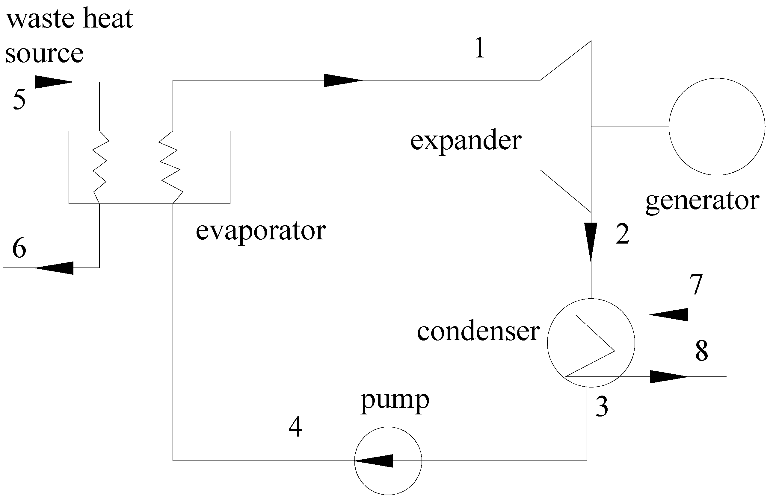
2. Thermodynamic Analysis of the Supercritical ORC

This supercritical ORC system consists of a working fluid pump, an evaporator driven by low-grade waste heat, an expander, and a water cooled condenser (Figure 1). The typical T-s process for the supercritical ORC system is shown in Figure 2.
Figure 1. Schematic diagram of the supercritical ORC system.
Energies 05 03233 g001
Figure 2. A typical T-s diagram of the supercritical ORC system.
Energies 05 03233 g002

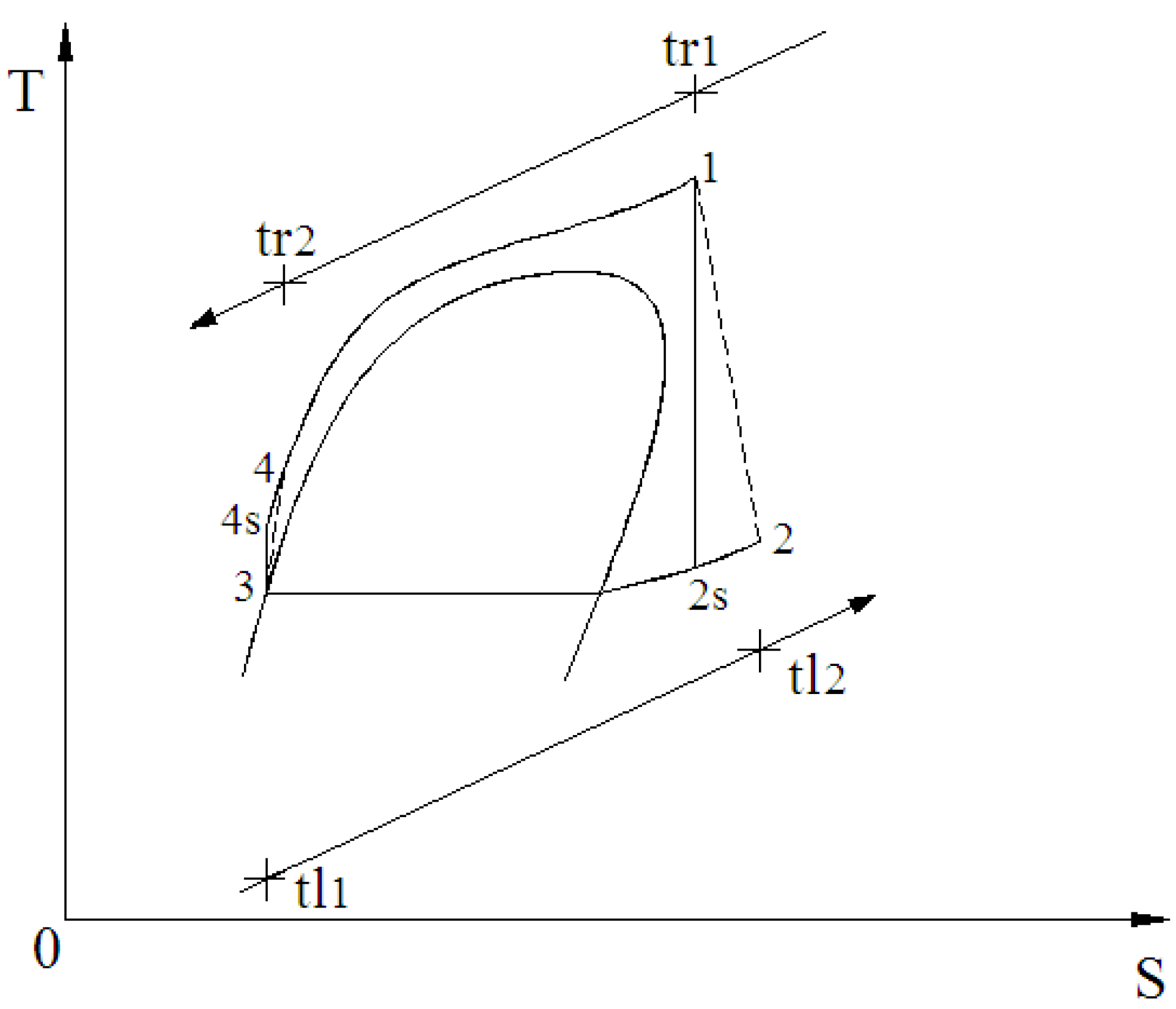
2.1. Process 3-4 (Pump)

The pump power can be expressed as:
W ˙ p = m ˙ ( h 4 s h 3 ) η p

2.2. Process 4-1 (Evaporator)

This is an isobaric heat absorption process. The evaporator heats the working fluid at the pump outlet to supercritical condition. The heat transfer rate from the evaporator into the working fluid is given by:
Q ˙ e = m ˙ ( h 1 h 4 )

2.3. Process 1-2 (Expander)

The superheated vapor working fluid passes through the expander to generate the mechanical power. For the ideal case, this is an isentropic process. The expander power is given by:
W ˙ t = m ˙ ( h 1 h 2 s ) η s

2.4. Process 3-4 (Condenser)

The exhaust vapor exits the expander and is led to the condenser where it is condensed by the cooling water. This is an isobaric condensation process. The condenser heat rate can be expressed as:
Q ˙ c = m ˙ ( h 2 h 3 )

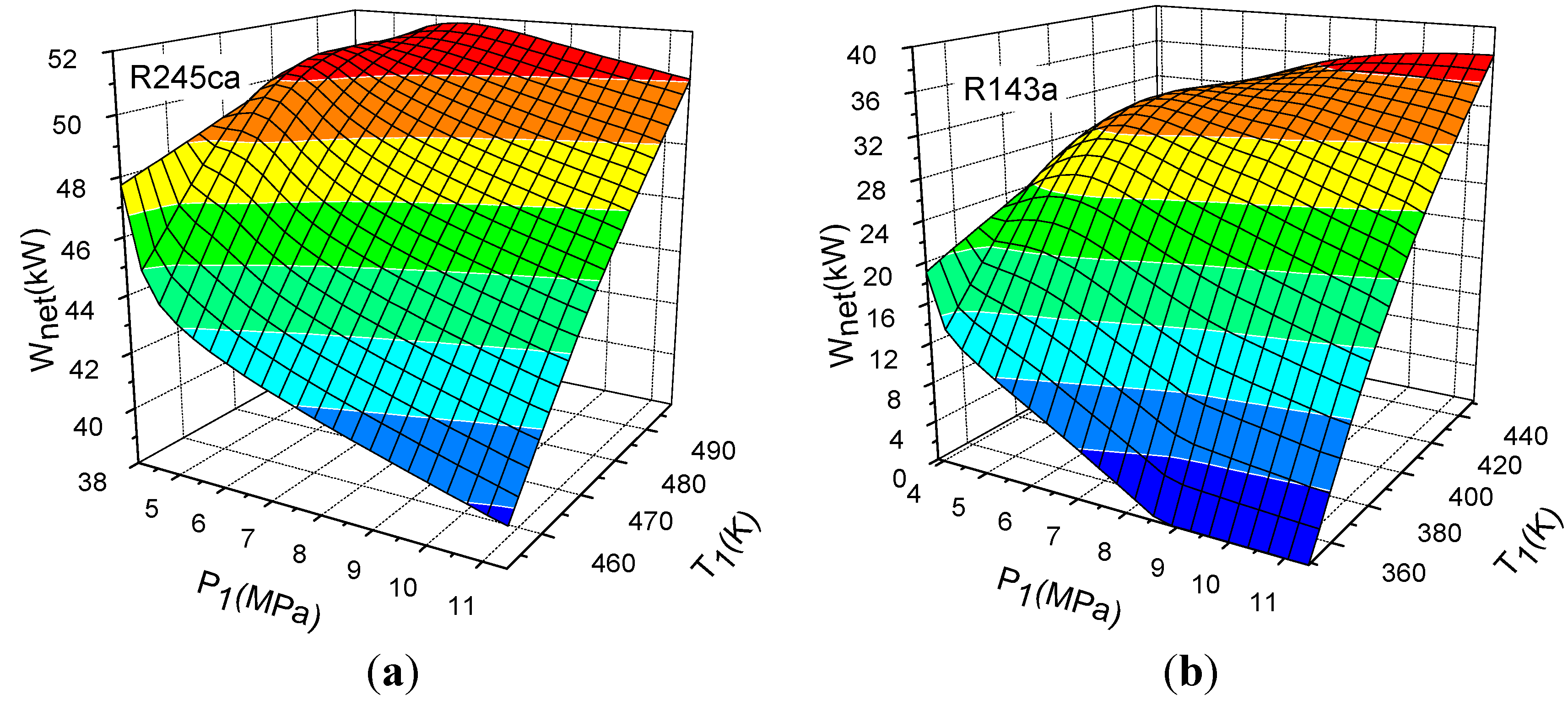
2.5. Net Power Output

W ˙ n e t = W ˙ t W ˙ p

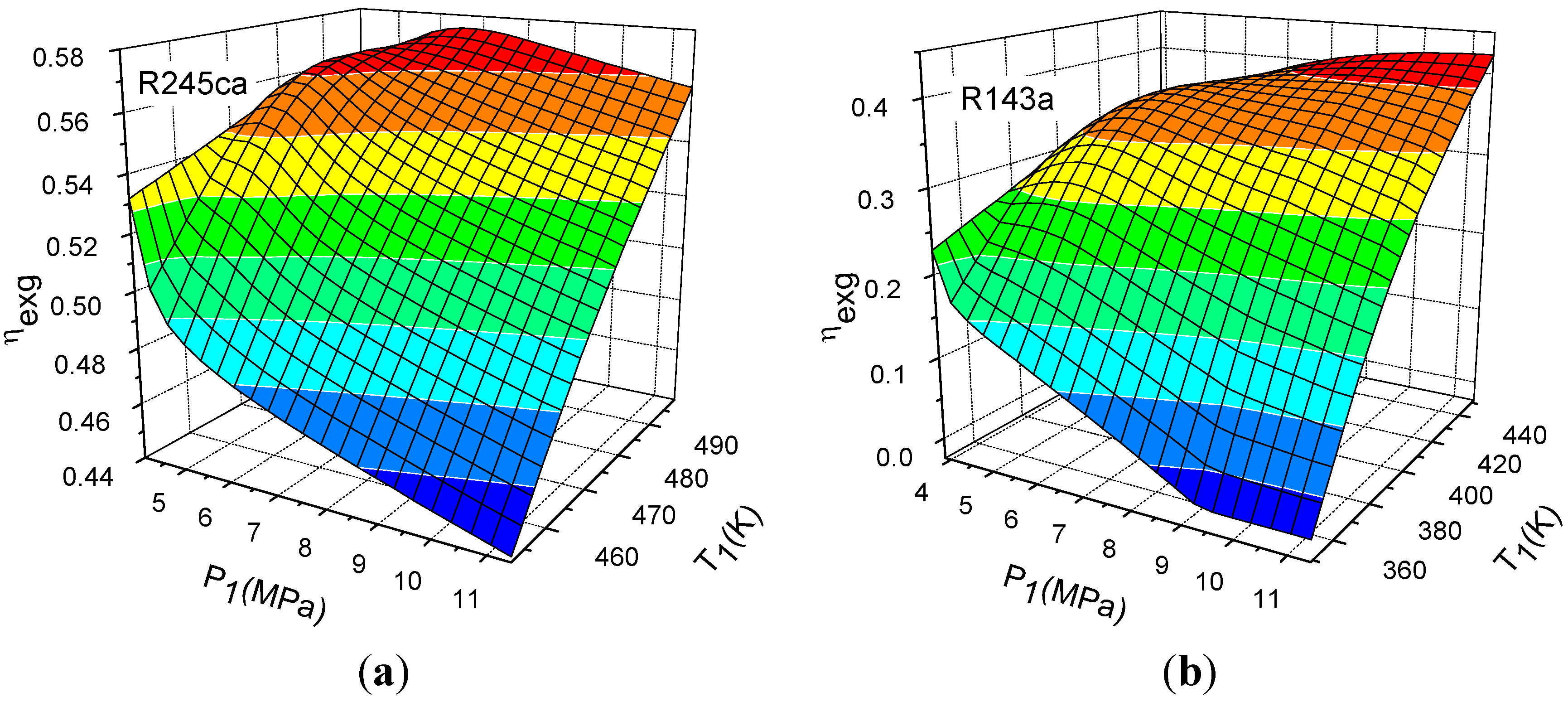
2.6. Exergy Efficiency

The thermal efficiency of the ORC is the ratio of the net power output to the heat addition. When comparing different working fluids under different operating conditions if the heat source of the inlet temperature and the pinch point are imposed, this definition could be misleading [26,27]. However, since the inlet, outlet temperatures and the flow rate of the heat source are imposed in this study, the variations the thermal efficiency is directly linked to the variations of Wnet. Moreover, because the thermal efficiency cannot reflect the ability to convert energy from low grade waste heat into usable work [28], the exergy efficiency is considered herein, which can be used to evaluate the performance for waste heat recovery.
Consider P0 and T0 to be the ambient pressure and temperature as the specified dead reference state. The exergy of the state point can be considered as:
E ˙ t = m ˙ [ ( h i h 0 ) T 0 ( s i s 0 ) ]
The exergy efficiency of ORC system can be expressed as:
η e x g = W ˙ n e t E ˙ i n p u t

2.7. Technical and Economic Factors

The total heat transfer requirement and the expander size are two important technical and economic factors in ORC system. The total heat transfer requirement (UA)tot, which has been used to evaluate the cost of heat exchangers, can approximately reflect the total heat transfer area of heat exchangers in the ORC system based on the hypothesis that the heat transfer coefficient differences of the working fluids are not very apparent. (UA)tot could be evaluated by the following equations [23,29,30]:
Energies 05 03233 i001
Energies 05 03233 i002
where ΔTm is the logarithmic mean temperature difference, ΔTmzx and ΔTmin are the maximal and minimal temperature differences at the ends of the heat exchangers, respectively.
Macchi [31] used the turbine SP to evaluate the expander size:
Energies 05 03233 i003
where V ˙ 2 s is the volume flow rate of the working fluid at the outlet of the expander and ΔHs is the specific enthalpy drop in the expander.
In this paper, the hypotheses are as follows: the system has reached the steady state, there is no pressure drop in the evaporator, pipes and condenser, the heat losses in the components are neglected, and isentropic efficiencies of the pump and expander are given. The state of working fluid at the expander inlet is supercritical vapor. The ORC specifications considered in this paper are given in Table 1. In order to determine which kinds of working fluid shows best performance under the same heat source conditions, waste heat source inlet and outlet temperature were imposed. The selection of working fluids is not for this particular heat source.
Table 1. Specifications of the supercritical ORC conditions (Waste heat source: hot air).
ParameterValueUnit
Waste heat source inlet temperature593 K
Waste heat source outlet temperature333K
Mass flow rate of waste heat source1kg/s
Condensing temperature303K
Cooling water inlet temperature293K
Cooling water outlet temperature297K
Ambient temperature293.15K
Ambient pressure100kPa
Isentropic efficiency of the expander85%
Pump isentropic efficiency70%
For the purpose of this study, 18 organic working fluids with low boiling points were employed. Some of the properties of fluids used in this investigation are presented in Table 2. The thermodynamic properties of working fluids are evaluated with REFPROP7.1 [32] developed by the National Institute of Standards and Technology of the United States.
Table 2. Properties of the organic fluids used in this investigation (Sequenced by the critical temperature).
FluidCritical PropertiesRange of Applicability a [32]
P (MPa)T (K)Minimum Temperature (K)Maximum Temperature (K)Maximum Pressure (MPa)
R1233.6618456.8316660040
R245ca3.925447.5720050060
R245fa3.64427.2020050060
Butane3.796425.13134.8758969
R236ea3.502412.4424250060
R142b4.07410.26142.7250060
Isobutene3.64407.82113.5657335
R236fa3.2398.07179.5250040
R1243.624395.4312047040
R152a4.5168386.41154.5650060
R227ea2.926374.80146.3550060
R134a4.059374.21169.8545570
Propylene4.664365.57100600200
R325.782351.26136.3443570
R143a3.761345.86161.34650100
R2182.671345.1011350030
R1253.617339.17172.5250060
R415.897317.2817550060
a Range of Applicability refers to the range of validation of the equation of state used in the database.

3. Results and Discussion

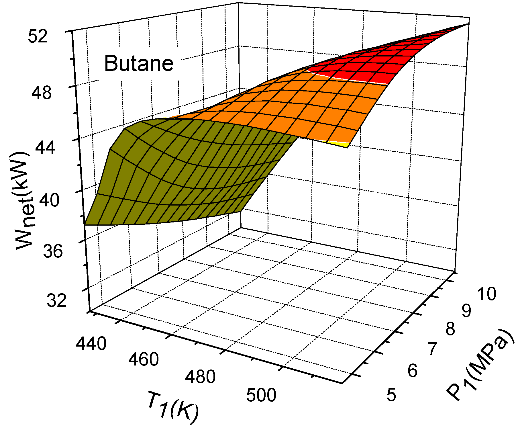
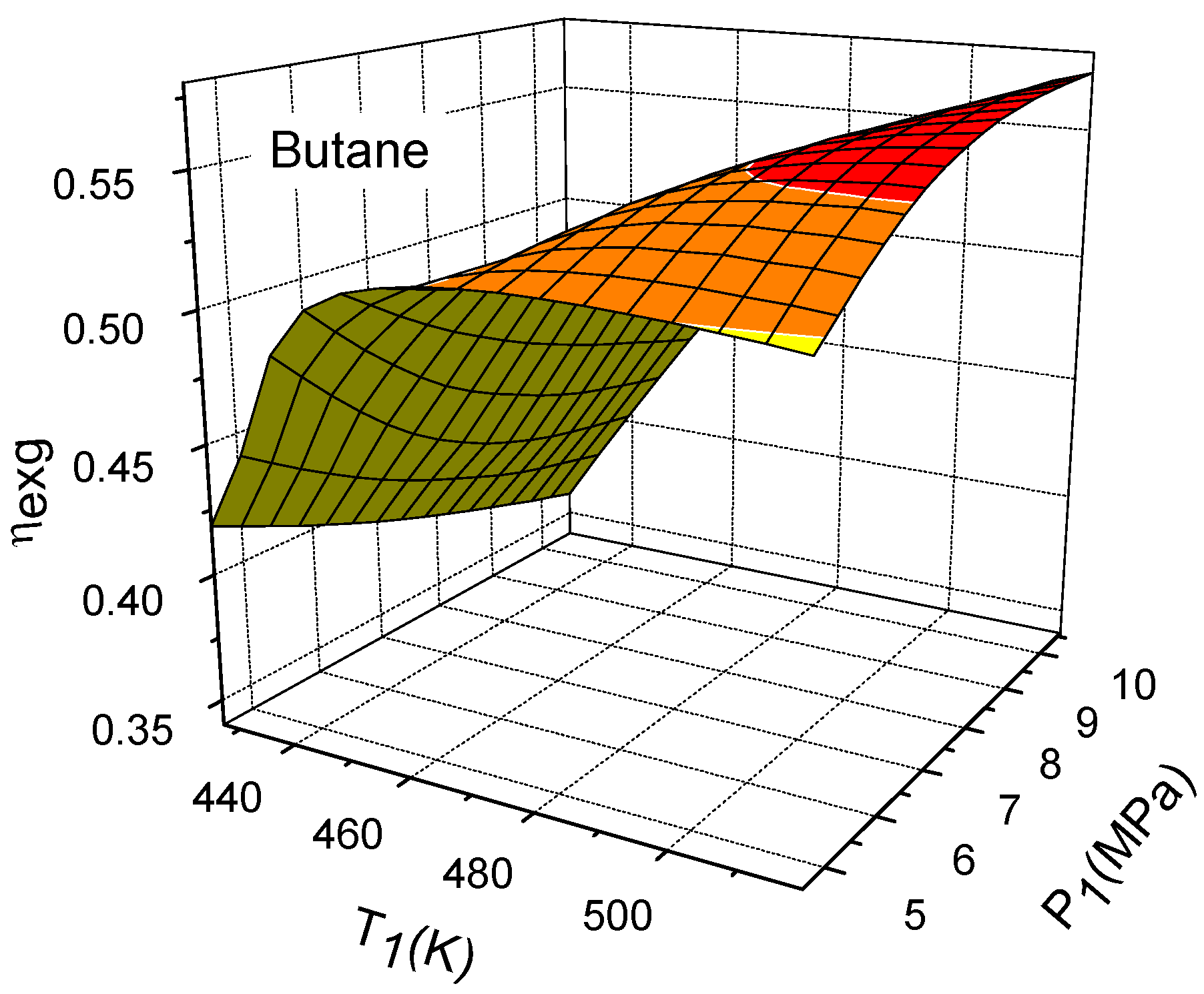
3.1. Influence of Expander Inlet Pressure

As shown in Figure 3a,b, with different working fluids, the influences of the expander inlet pressure on the net power are different. As shown in Figure 3a, with the working fluids of moderate boiling temperature, such as R245ca, when the expander inlet temperature is about 472 K or 499 K, there is an optimal pressure for maximum net power output. However, when the expander inlet temperature is 452 K, there is a decline of the net power with the increase of the expander inlet pressure. With the working fluids except the above mentioned (Figure 3b), when the expander inlet temperature is 349 K, higher expander inlet pressure results in a lower net power output. Only the high expander inlet temperature (452 K) could make the net power output increase with the increase of the expander inlet pressure monotonously.
Figure 4a,b shows the variations of the exergy efficiency with the expander inlet pressure. Since the inlet, outlet temperatures and the flow rate of the heat source are imposed, the variation of the exergy efficiency is directly linked to the variation of Wnet. As a consequence, the exergy efficiency and Wnet show the same evolution.
From Figure 3 and Figure 4, it can be seen that when the expander inlet temperature is low, increasing the expander inlet pressure could not improve the net power output and the exergy efficiency. Generally, for most fluids in this study, more net power output of supercritical ORC requires either lower expander inlet temperature and pressure, or higher expander inlet temperature and pressure.
Figure 3. Variation of the net power output with expander inlet pressure. (a) R245ca; (b) R143a.
Energies 05 03233 g003
Figure 4. Variations of the exergy efficiency with expander inlet pressure and temperature. (a) R245ca; (b) R143a.
Energies 05 03233 g004

3.2. Influence of Expander Inlet Temperature

As shown in Figure 5, for butane, the system net power output increases with the increase of the expander inlet temperature monotonously except when the expander inlet pressure is 4.6 MPa. The net power output curves of working fluids R32, R41, R123, R124, R125, R134a, R142b, R143a, R218, R236ea, R245ca, R245fa, Isobutene, Propylene, R152a, R227ea, and R236fa have similar trends.
Figure 6 shows the variations of the exergy efficiency with the expander inlet temperature. It can be observed that the variation trends of the exergy efficiency are similar to that of the net power output.
Figure 5 and Figure 6 reflect the fact that the higher expander inlet temperature will benefit the net power output and exergy efficiency, as long as the expander inlet pressure isn’t too low. In other words, increasing the expander inlet temperature could improve the performance of the supercritical ORC system.
Figure 5. Variation of the net power output with expander inlet temperature and pressure.
Energies 05 03233 g005
Figure 6. Variations of the exergy efficiency with expander inlet temperature and pressure.
Energies 05 03233 g006

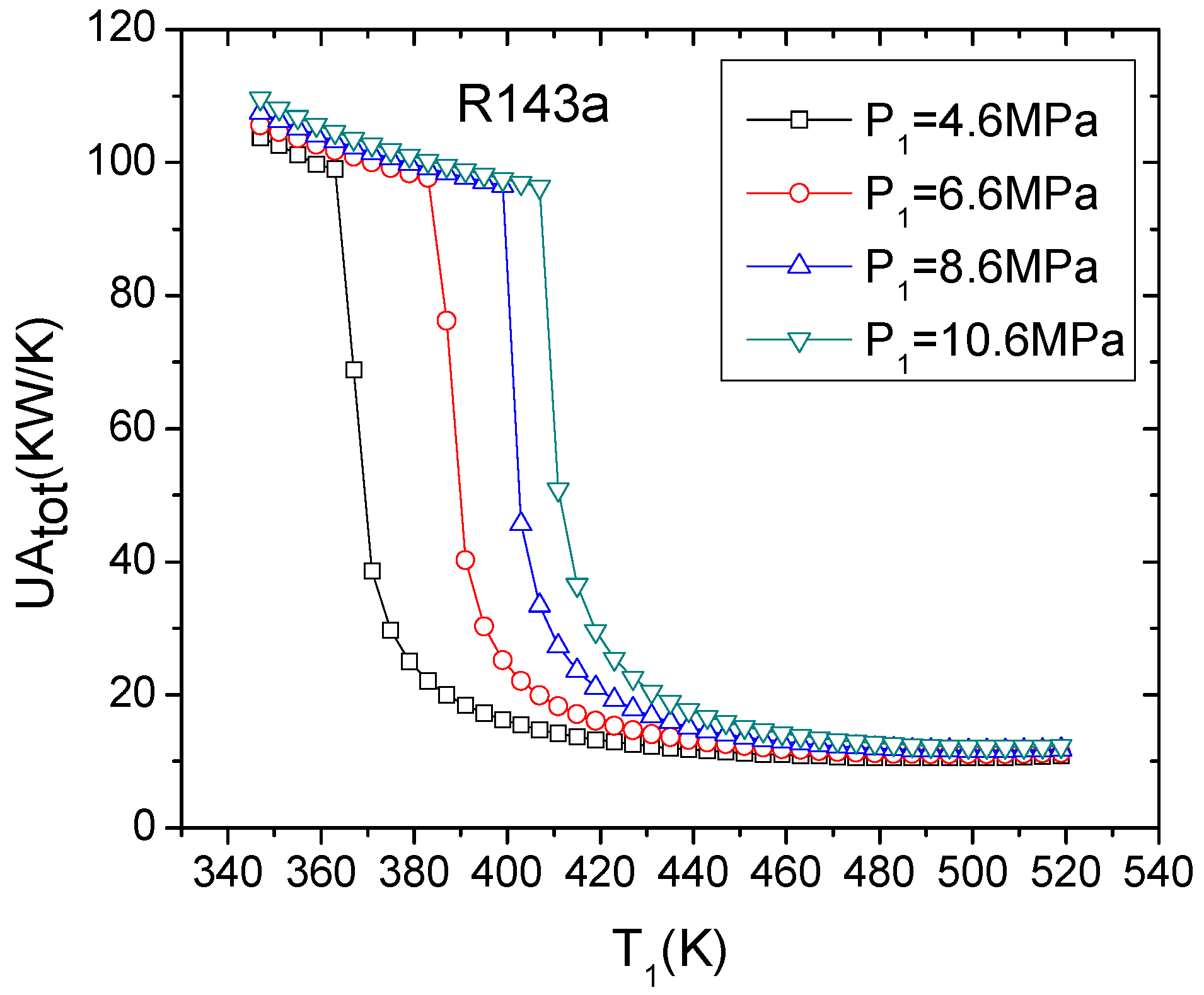
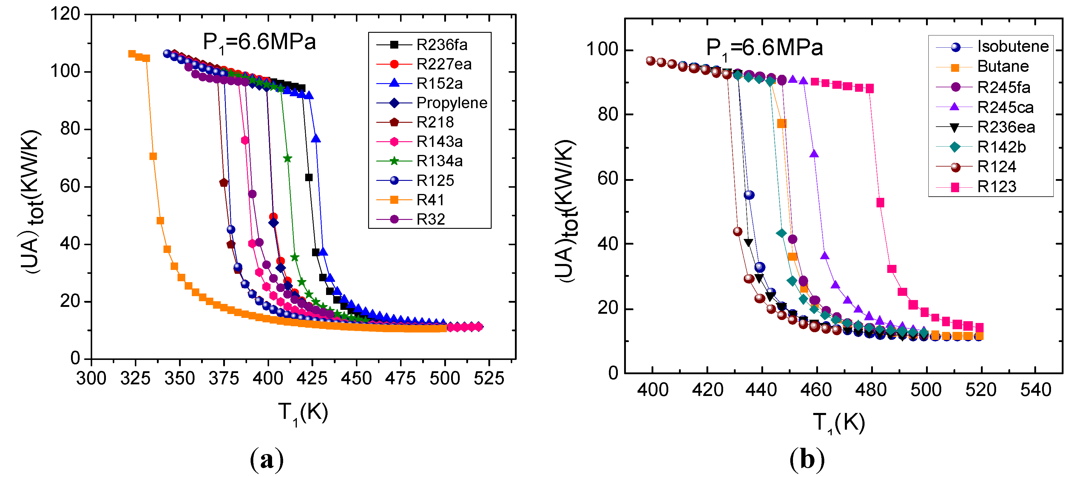
3.3. Total Heat Transfer Requirement ((UA)tot)

From the hypothesis mentioned above, generally, the higher total heat transfer requirement means more cost of the heat exchanger. As it is seen from Figure 7, if the expander outlet point is in the two-phase region, (UA)tot is very large. For example, when the expander inlet temperature and pressure are 347 K and 10.6 MPa, respectively, the (UA)tot is about 109.638 kW/K for R143a. Owing to the very small temperature difference, the heat transfer requirement of condenser is huge. Due to the same reason, i.e., the small temperature difference for heat transfer, the condenser (T3 = 303 K) ontributes more areas to the total heat transfer area in this investigation.
As shown in Figure 7, either lower expander inlet temperature or higher expander inlet pressure results in larger total heat transfer requirement.
Figure 7. Variation of the total heat transfer requirement with expander inlet temperature.
Energies 05 03233 g007

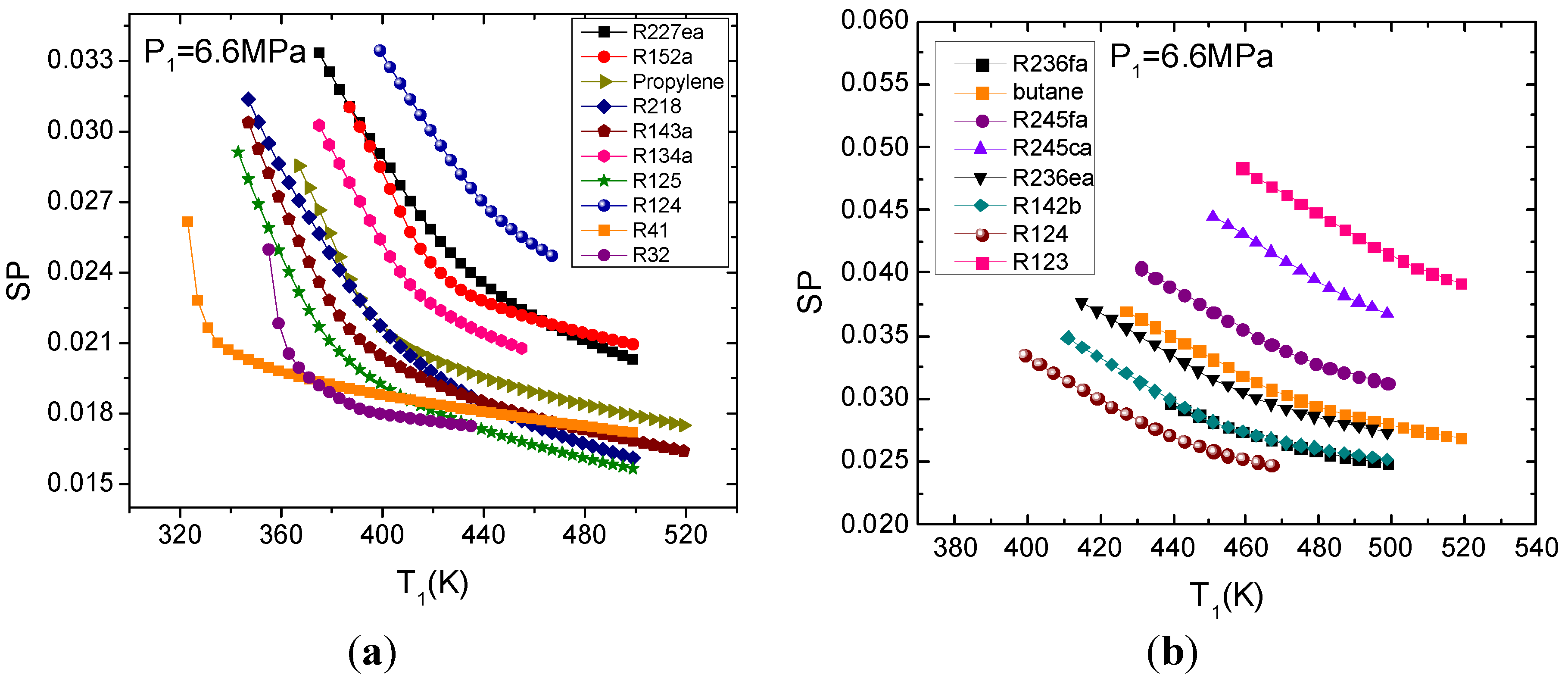
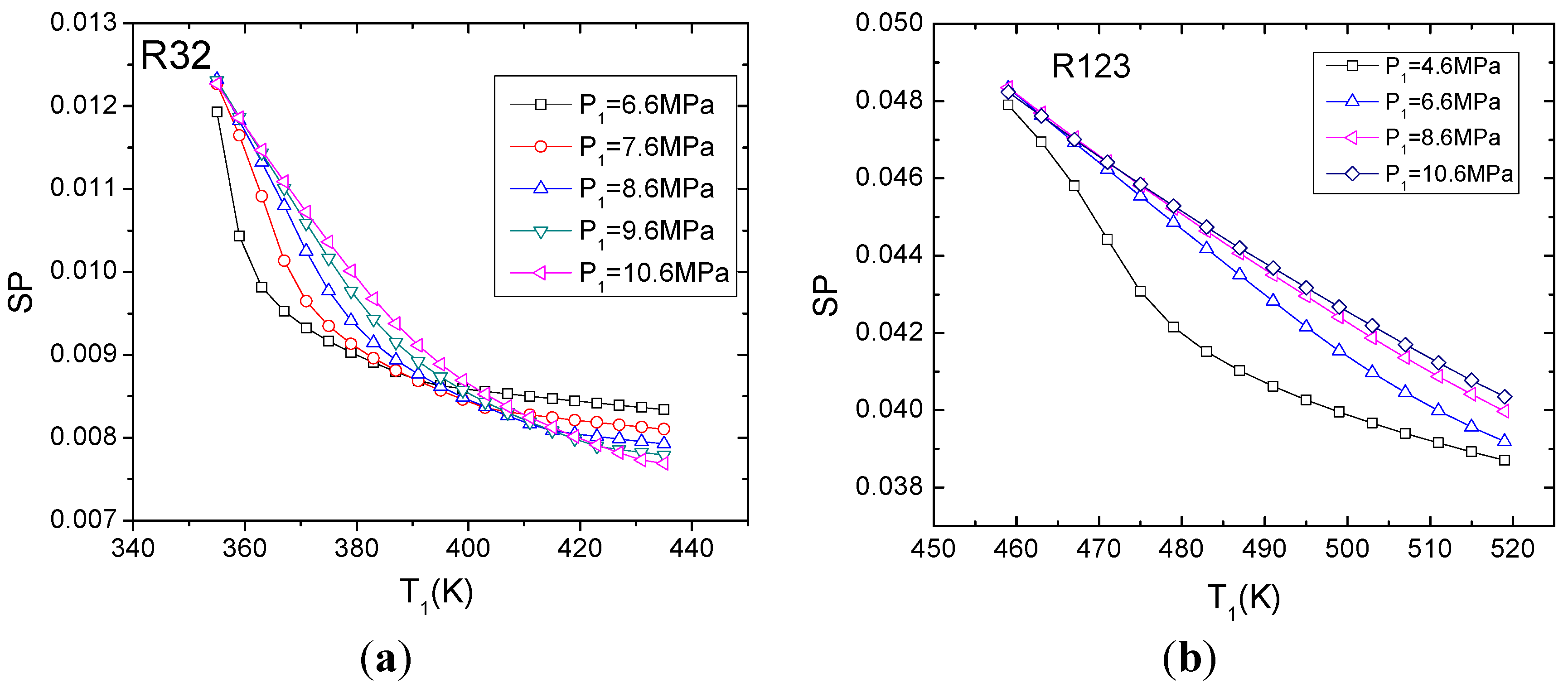
3.4. Expander Size Parameter (SP)

Figure 8 illustrates the influence of expander inlet pressure and temperature on the expander size parameter. SP always decreases as the expander inlet temperature increases. However, how the expander inlet pressure influences SP is an interesting problem. It is related to the working fluids. For R32a, when the expander inlet temperature is less than 400 K, the higher expander inlet pressure makes the larger SP. However, if the expander inlet temperature is greater than 400 K, lower pressure leads to larger SP instead (Figure 8a). R41, R125, R143a, R218, propylene, R152a, R227ea have similar SP curves. For R123, higher expander inlet pressure results in larger SP. Similar working fluids are R124, R134a, R142b, R236ea, R245ca, R245fa, butane, isobutene, R236fa (Figure 8b).
Figure 8. Variation of expander size parameter with the expander inlet temperature. (a) R32; (b) R123.
Energies 05 03233 g008

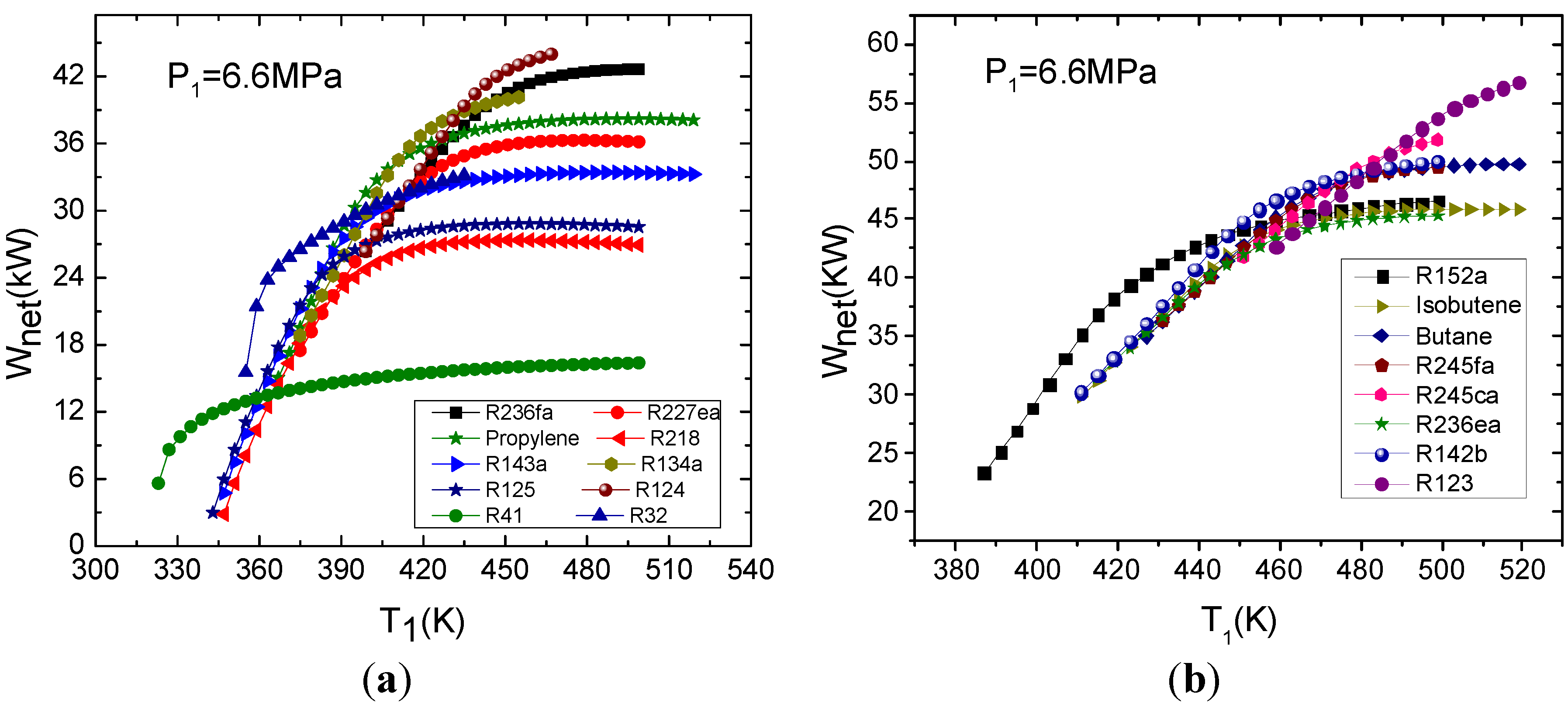
3.5. Choice of the Working Fluids

The organic working fluid must be carefully selected on the basis of safety and technical feasibility. Generally, a good working fluid should exhibit low toxicity, good material compatibility and fluid stability limits, and low flammability, corrosion, and fouling characteristics. Besides these general characteristics, system performance is another important factor that must be considered. Another important aspect of this paper is the selection of the suitable working fluids based on the system performance analysis. The screening criteria are maximum net power output, maximum thermal efficiency, maximum exergy efficiency, minimum heat transfer area, and minimum SP.
Figure 9 illustrates the net power output curves of 18 working fluids. Among these working fluids, eight organic fluids, which are R152a, isobutene, butane, R245fa, R245ca, R236ea, R142b, and R123, have more net power output. Because the exergy efficiency curves have similar variation trends with Wnet, for the sake of simplicity, here we just provide the net power output curves.
With the expander inlet pressure of 6.6 MPa, if the expander inlet temperature is less than 450 K, R152a and R142b are better choices. Under this condition, the net power output differences of the other seven working fluids are small. If the inlet temperature of expander is greater than 450 K, supercritical ORC systems using R123, R245ca, R142b, Butane, and R245fa as working fluids show better performance.
Figure 10 and Figure 11 illustrate the total heat transfer requirement and SP comparisons of different working fluids. Figure 10a and Figure 11a just present the 10 working fluids that have smaller (UA)tot and SP.
From Figure 10a, it is found that the (UA)tot differences among the 10 working fluids are large if the expander inlet temperature is relatively low. When the expander inlet temperature is about greater than 480 K, the (UA)tot differences get smaller. From Figure 10, the discontinuity in the curves was found. There are two reasons leading to the discontinuity in the curves possibly. Firstly, if the expander outlet point is in the two-phase region, (UA)tot is very large because of the very small temperature difference. If expander outlet point is in the superheated region, the temperature difference of heat transfer becomes larger and (UA)tot deceases greatly. Secondly, the interval of calculation is large. In the view of minimum total heat transfer area, R41, R218, and R125 are more suitable working fluids.
According to the screening criterion of SP, R32 and R41 might be recommended.
Figure 9. The comparison of net power output for different working fluids. (a) 10 working fluids; (b) 8 working fluids.
Energies 05 03233 g009
Figure 10. The comparison of total heat transfer requirement of different working fluids. (a) 10 working fluids; (b) 8 working fluids.
Energies 05 03233 g010
Figure 11. The comparison of SP of different working fluids. (a) 10 working fluids; (b) 8 working fluids.
Energies 05 03233 g011
Even though only one expander inlet pressure is shown in Figure 9, Figure 10 and Figure 11, the authors verified that the performances of other pressures are similar to the one presented here. After comparing Figure 9, Figure 10 and Figure 11, it is found that the selected working fluids are totally different according to the screening criteria of net power output, (UA)tot and SP. In another words, it is difficult to choose a working fluid which meets the requirements of the maximum output and the minimum investment at the same time. More net power output means the larger heat transfer area and expander size definitely, so it is hard to select the perfect working fluid that can satisfy all screening criteria. As a compromise, R152a and R143a would be recommended according to the criteria mentioned above.

4. Conclusions

This paper presents an analysis of the performance of supercritical ORC using 18 organic working fluids. This analysis was conducted basing on the basic thermodynamic theory, and parameters such as net power output, exergy efficiency, total heat transfer requirement, and SP were evaluated and compared among 18 working fluids. Based on system performance analysis, the suitable working fluids were chosen according to the screening criteria, i.e., maximum net power, maximum cycle efficiency, maximum exergy efficiency, minimum total heat transfer requirement, and minimum expander size.
From the above discussion, the following conclusions can be reached:
(1)
The higher expander inlet temperature will benefit the net power output and exergy efficiency, as long as the expander inlet pressure isn’t too low. However, the influences of expander inlet pressure on these performance parameters are linked with the expander inlet temperature and working fluids. Generally, more net power output of supercritical ORC requires either lower expander inlet temperature and pressure, or higher expander inlet temperature and pressure.
(2)
Either higher expander inlet pressure or lower expander inlet temperature results in larger total heat transfer requirement.
(3)
Higher expander inlet temperature leads to smaller expander size. For some working fluids, such as R32, R41, R125, R143a, and so on, either lower expander inlet temperature and pressure, or higher expander inlet temperature and pressure, makes the expander size smaller. For other working fluids, such as R123, R124, R134a, and so on, higher expander inlet pressure brings on a larger SP.
(4)
It is difficult to choose a working fluid which could satisfy the requirements of both the maximum output and the minimum investment at the same time. As a compromise, R152a and R143a are recommended as the working fluids in this paper.
It is noted that, in this paper, although the optimal working fluids were recommended according to the screening criteria, a multi-objective optimization model was not proposed. Also, because this study mainly aims at the thermodynamic analysis of ORC system, the thermal stability of working fluids in high temperature and pressure was not considered in this paper. Those are the parts to be improved in the further studies.

Symbols and Abbreviations:

Eexergy (kJ s−1)Greek symbols
hspecific enthalpy (kJ kg−1)ηefficiency (dimensionless)
ΔHsisentropic enthalpy difference in the expander (J kg−1)Subscripts
Iexergy loss (kJ s−1)ccondenser
m ˙ mass flow rate (kg s−1)eevaporator
Q ˙ heat transfer rate (kJ kg−1)expexpander
sspecific entropy (kJ kg−1)inputsystem input
SPthe expander size parameternetnett
Ttemperature (K)outputsystem output
(UA)the total heat transfer requirement (kW K−1)ppump
Wpower (kW)tottotal
1–4, istate points

Acknowledgments

This work was supported by National Basic Research Program of China (973 Program) under Grant No. 2011CB710701.

References

  1. Di Pippo, R. Second law assessment of binary plants generating power from low-temperature geothermal fluids. Geothermics 2004, 33, 565–586. [Google Scholar] [CrossRef]
  2. Badr, O.; O’Callaghan, P.W. Thermodynamic and thermophysical properties of organic working fluids for Rankine cycle engines. Appl. Energy 1985, 19, 1–40. [Google Scholar] [CrossRef]
  3. Yamamoto, T.; Furuhata, T.; Arai, N.; Mori, K. Design and testing of the organic Rankine cycle. Energy 2001, 26, 239–251. [Google Scholar] [CrossRef]
  4. Madhawa Hettiarachchi, H.D.; Golubovic, M.; Worek, W.M.; Ikegami, Y. Optimum design criteria for an organic Rankine cycle using low-temperature geothermal heat sources. Energy 2007, 32, 1698–1706. [Google Scholar] [CrossRef]
  5. Mago, P.J.; Chamra, L.M.; Srinivasan, K.; Somayaji, C. An examination of regenerative organic Rankine cycles using dry fluids. Appl. Therm. Eng. 2008, 28, 998–1007. [Google Scholar] [CrossRef]
  6. Wei, D.H.; Lu, X.S.; Lu, Z.; Gu, J.M. Dynamic modeling and simulation of an organic Rankine cycle (ORC) system for waste heat recovery. Appl. Therm. Eng. 2008, 28, 1216–1224. [Google Scholar] [CrossRef]
  7. Wei, D.H.; Lu, X.S.; Lu, Z.; Gu, J.M. Performance analysis and optimization of organic Rankine cycle (ORC) for waste heat recovery. Energy Convers. Manag. 2007, 48, 1113–1119. [Google Scholar] [CrossRef]
  8. Chen, H.J.; Goswami, D.Y.; Stefanakos, E.K. A review of thermodynamic cycles and working fluids for the conversion of low-grade heat. Renew. Sustain. Energy Rev. 2010, 14, 3059–3067. [Google Scholar] [CrossRef]
  9. Drescher, U.; Bruggemann, D. Fluid selection for the organic Rankine cycle (ORC) in biomass power and heat plants. Appl. Therm. Eng. 2007, 27, 223–228. [Google Scholar] [CrossRef]
  10. Saleh, B.; Koglbauer, G.; Wendland, M.; Fischer, J. Working fluids for low temperature organic Rankine cycles. Energy 2007, 32, 1210–1221. [Google Scholar] [CrossRef]
  11. Liu, B.T.; Chien, K.; Wang, C. Effect of working fluids on organic Rankine cycle for waste heat recovery. Energy 2004, 29, 1207–1217. [Google Scholar] [CrossRef]
  12. Hung, T.C. Waste heat recovery of organic Rankine cycle using dry fluids. Energy Convers. Manag. 2001, 42, 539–553. [Google Scholar] [CrossRef]
  13. Hung, T.C.; Shai, T.Y.; Wang, S.K. A review of organic Rankine cycles (ORCs) for the recovery of low-grade waste heat. Energy 1997, 22, 661–667. [Google Scholar] [CrossRef]
  14. Lee, K.M.; Kuo, S.F.; Chien, M.L.; Shih, Y.S. Parameters analysis on organic Rankine cycle energy recovery system. Energy Convers. Manag. 1988, 28, 129–136. [Google Scholar] [CrossRef]
  15. Wang, Z.Q.; Zhou, N.J.; Guo, J.; Wang, X.Y. Fluid selection and parametric optimization of organic Rankine cycle using low temperature waste heat. Energy 2012, 40, 107–115. [Google Scholar] [CrossRef]
  16. Chen, Y.; Lundqvist, P.; Johansson, A.; Platell, P. A comparative study of the carbon dioxide transcritical power cycle compared with an organic Rankine cycle with R123 as working fluid in waste heat recovery. Appl. Therm. Eng. 2006, 26, 2142–2147. [Google Scholar] [CrossRef]
  17. Zhang, X.R.; Yamaguchi, H.; Uneno, D. Experimental study on the performance of solar Rankine system using supercritical CO2. Renew. Energy 2007, 32, 2617–2628. [Google Scholar] [CrossRef]
  18. Zhang, X.R.; Yamaguchi, H.; Uneno, D. Thermodynamic analysis of the CO2-based Rankine cycle powered by solar energy. Int. J. Energy Res. 2007, 31, 1414–1424. [Google Scholar] [CrossRef]
  19. Zhang, X.R.; Yamaguchi, H.; Fujima, K.; Enomoto, M.; Sawada, N. Theoretical analysis of a thermodynamic cycle for power and heat production using supercritical carbon dioxide. Energy 2007, 32, 591–599. [Google Scholar] [CrossRef]
  20. Karellas, S.; Schuster, A. Supercritical fluid parameters in organic Rankine cycle applications. Int. J. Thermodyn. 2008, 11, 101–108. [Google Scholar]
  21. Schuster, A.; Karellas, S.; Aumann, R. Efficiency optimization potential in supercritical organic Rankine cycles. Energy 2010, 35, 1033–1039. [Google Scholar] [CrossRef]
  22. Chen, H.J.; Goswami, D.Y.; Rahman, M.M.; Stefanakos, E.K. A supercritical Rankine cycle using zeotropic mixture working fluids for the conversion of low-grade heat into power. Energy 2011, 36, 549–555. [Google Scholar] [CrossRef]
  23. Karellas, S.; Schuster, A.; Leontaritis, A.D. Influence of supercritical ORC parameters on plate heat exchanger design. Appl. Therm. Eng. 2012, 33–34, 70–76. [Google Scholar]
  24. Pan, L.S.; Wang, H.X.; Shi, W.X. Performance analysis in near-critical conditions of organic Rankine cycle. Energy 2012, 37, 281–286. [Google Scholar] [CrossRef]
  25. Khennich, M.; Galanis, N. Optimal design of ORC systems with a low-temperature heat source. Entropy 2012, 14, 370–389. [Google Scholar] [CrossRef]
  26. Lakew, A.A.; Bolland, O. Working fluids for low-temperature heat source. Appl. Therm. Eng. 2010, 30, 1262–1268. [Google Scholar] [CrossRef]
  27. Quoilin, S.; Declaye, S.; Tchanche, B.F.; Lemort, V. Thermo-economic optimization of waste heat recovery organic Rankine cycles. Appl. Therm. Eng. 2011, 31, 2885–2893. [Google Scholar] [CrossRef]
  28. Dai, Y.P.; Wang, J.F.; Gao, L. Parametric optimization and comparative study of organic Rankine cycle (ORC) for low grade waste heat recovery. Energy Convers. Manag. 2009, 50, 576–582. [Google Scholar] [CrossRef]
  29. Guo, T.; Wang, H.X.; Zhang, S.J. Comparative analysis of CO2-based transcritical Rankine cycle and HFC245fa-based subcritical organic Rankine cycle using low-temperature geothermal source. Sci. China 2010, 53, 1638–1646. [Google Scholar] [CrossRef]
  30. He, C.; Liu, C.; Gao, H.; Xie, H.; Li, Y.R.; Wu, S.Y.; Xu, J.L. The optimal evaporation temperature and working fluids for subcritical organic Rankine cycle. Energy 2012, 38, 136–143. [Google Scholar] [CrossRef]
  31. Macchi, E.; Perdichizzi, A. Efficiency prediction for axial-flow turbines operating with non conventional fluids. J. Eng. Power Trans. ASME 1981, 103, 718–724. [Google Scholar] [CrossRef]
  32. McLinden, M.O. REFPROP, Version 7.1; NIST Standard Reference Database 23; The US Department of Commerce: Boulder, CO, USA, 2003. [Google Scholar]

