1. Introduction
The development of distributed generation systems, and especially microgrids, has increased considerably in recent years due to the pressures of environmental protection and the energy crisis. Many countries, such as U.S., E.U., Japan and Canada, have established a great number of microgrid demonstration projects [
1,
2] and incorporated microgrids into the development agenda of future electric grids [
3,
4,
5]. Under these circumstances, the penetration of microgrids has increased rapidly and gradually reached significant levels, which has drawn much attention from researchers to solve the communication and control problems caused by the high penetration of distributed generation within the distribution network. Various control strategies for specific application scenarios are proposed [
6,
7,
8]. In an overall view, the control strategies may be classified into two sets—the hierarchical control and fully decentralized control [
9]. Hierarchical control systems may have centralized or decentralized controllers to provide a more or less decentralized decision making process [
10,
11,
12]; fully decentralized control aims to maximize the autonomy of the microsources and loads for fully decentralized processing. Several artificial intelligence based algorithms, such as MAS [
13] and gossip-based algorithms [
14], are cardinal implementations of the decentralized control. Amongst these control strategies, MAS seeks to divide a large complex system into smaller and easy-to-manage subsystems coordinating with each other for a common goal in a distributed way, which is proven to be ideal for microgrid control [
15,
16,
17,
18,
19]. However, most of these research works and its latest development are majorly based on laboratory facilities [
20] or small-scale demo projects built on campus [
21]. As for the modern electric grid, a trend is becoming apparent in that a large number of distributed microgrids will be integrated into the electric grid. In this case, a MAS with single level of equal peers is hard to make function effectively in the grid and is also difficult to scale.
Based on these observations and inspired by previous works, a hierarchical MAS control framework with three levels, including a distribution master station level, a distribution substation level and a distribution terminal level (or component level) is presented in this paper. The responsibilities of agents on each level are described. The issues of how to realize the MAS based control and how to improve the coordination control strategies are discussed. Basic simulation results are presented to confirm the effectiveness of the proposed hierarchical MAS control system.
2. Overview of Modern Electric Grid
The modern electric grid integrates electrical and information technologies in-between generation and consumption. Two kinds of infrastructures,
i.e. the electric power supply system and the information infrastructure to control the supply process, produce power flows and information flows in the system.
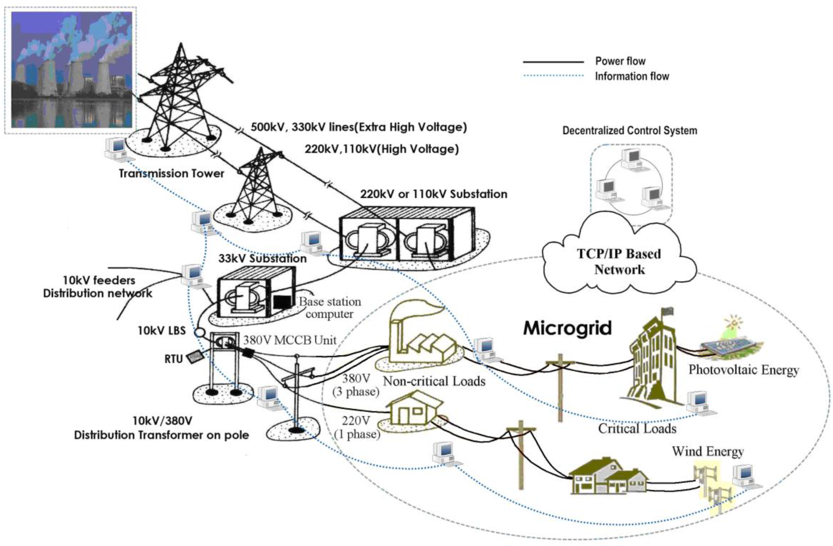
Figure 1 illustrates a general framework of a modern electric grid consisting of a power system with generation, transmission and distribution sections, microgrids and a decentralized control system. The black solid line represents the power flows, and the blue dotted line represents information flows. As an example, one microgrid is powered by photovoltaic generators and another by wind energy generators. Each microgrid is equipped with electrical loads (which are classified as critical and non-critical loads), and a distribution network that allows power to flow from the sources to the loads. Controllable breakers can govern the interconnection of these elements. The power loads are supplied by both microgrids and low voltage (LV) substations. Power is allocated based on the policy that when encountering a power failure such as an “outage”, the microgrid takes priority to ensure the power supply for critical loads. Decentralized control system consists of many control units deployed along the power flows in order to sense the status of the electric grid and make collective decisions about how to respond to user requests, expected events, and unplanned contingencies. The microgrid is incorporated into the electric grid at the LV substation. In this paper, we focus on the information flows of a hierarchical MAS-based control system for high penetration of microgrids in an electric grid. The simulation presented in
Section 3 is based on the framework described in this section.
Figure 1.
An overall framework of a modern electric grid.
Figure 1.
An overall framework of a modern electric grid.
2.1. Communication and Control System Based on MAS
A modern electric grid can be viewed as a large complex and distributed system which contains many subsystems. In a conventional electric grid, control strategies are accomplished by Supervisory control and data acquisition (SCADA) systems [
22,
23]. However, with SCADA, as a centralized control strategy, it is hard to achieve a platform-independent control for distributed microgrids [
9], so the deployment of MASs for the control of microgrid has recently been proposed to overcome this drawback [
24,
25]. MAS, as a main area of distributed artificial intelligence, is considered facilitate the design of complex systems [
26]. The idea behind any MAS is to divide a complex problem handled by a centralized system into smaller and simpler problems handled by a distributed system with several entities [
27,
28].
Compared with the traditional centralized control mode, a MAS has the following advantages: firstly, MAS offers various advantages over the SCADA system for the implementation of a modern electric grid; many MAS development toolkits are available as open source software, and most of the toolkits are Java based, which makes them platform-independent; secondly, Multi-agent technology can meet the trend of electric grids to make optimal use of distributed energy resources (DER); thirdly, a MAS has advantages of self-determination, self-inspiration, easy management and convenience to divide a large complex system into smaller systems, and each agent for the small system can take autonomous decisions, such as mode-switching of microgrids, load-shedding, securing critical loads,
etc. [
29,
30]. So it is easy for a MAS to achieve distributed control and management for electric grid.
Based on these advantages, MAS technology has been applied in electric grids for a range of applications, including power system disturbance diagnosis [
31], condition monitoring [
32], power system restoration [
33], market simulation [
34,
35], power system secondary voltage control [
36], power system visualization [
37] and automation [
38]. Moreover, the technology is maturing to the point where the first MAS are now being migrated from the laboratory to the utilities, allowing industry to gain experience in the use of MAS and also to evaluate their effectiveness [
39]. A review of this large body of work has been made by Stephen
et al. [
40].
2.2. Hierarchical MAS
While a trend that more and more microgrids are penetrating into electric grids is becoming apparent, a MAS with a single level of equal peers is hard to make function well in a modern electric grid and shows weak scalability. Oyarzabal
et al. [
41] proposed a decentralized control system based on MAS with two function levels,
i.e. microgrid central controller (MGCC) and its two subordinates - the microsources controller and load controller. Pipattanasomporn
et al. [
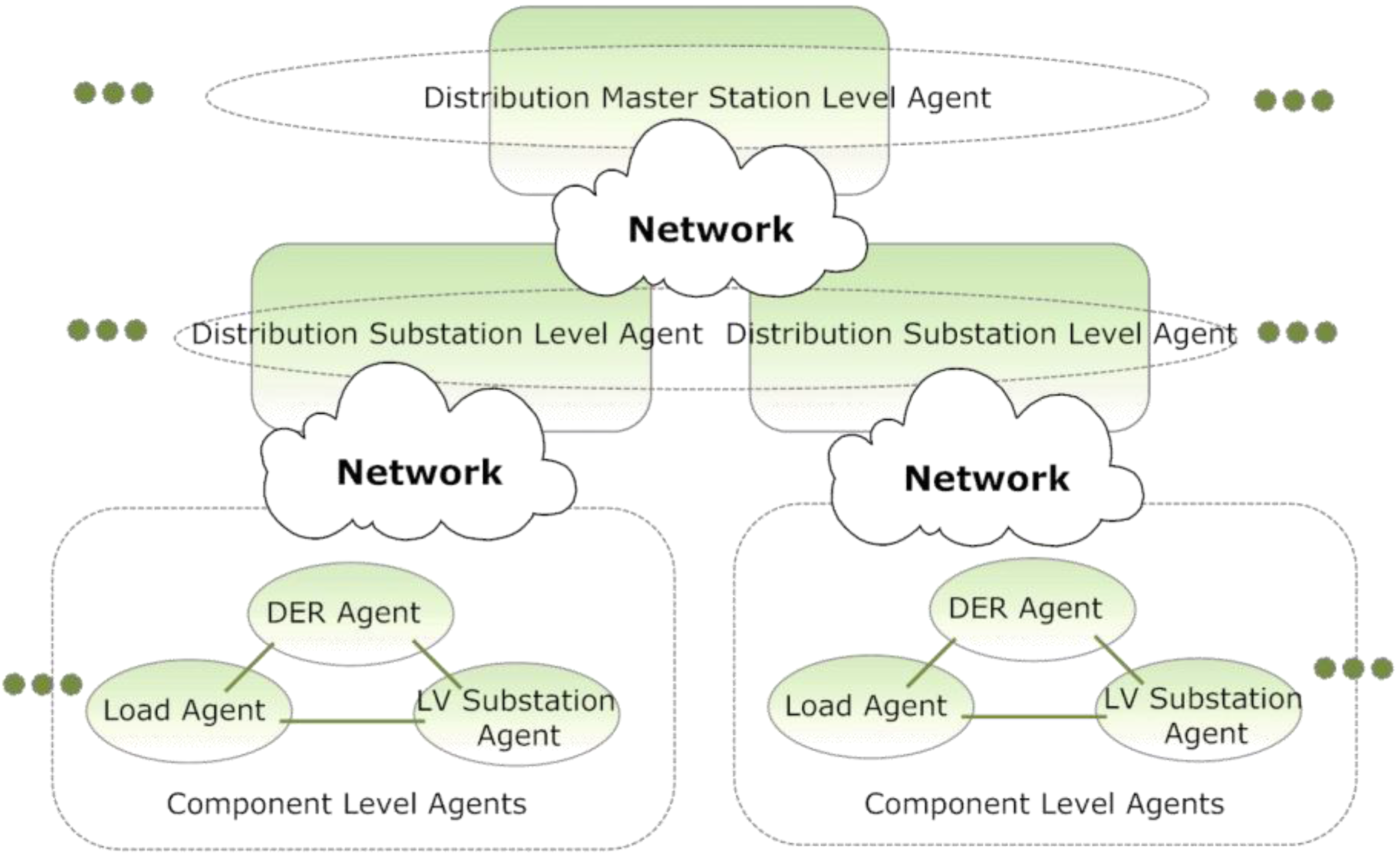
21] designed and implemented a MAS in which agents can directly control the components of microgrid for time-sensitive operations. Inspired by these works, we propose a hierarchical control system based on MAS which is composed of three levels of agents—a distribution master station level, a distribution substation level and a distribution terminal level agents (or component level agents), as shown in
Figure 2.
Figure 2.
The relationship of different level agents in hierarchical MAS.
Figure 2.
The relationship of different level agents in hierarchical MAS.
The distribution master station level is the highest level on which the agents are assigned with the tasks of managing many substations and to schedule the overall electric grid. Distribution substation level agents need to manage all the distribution terminals in a divisional region to gather the running state of microgrids. Distribution terminal level agents including DER agents, load agents and LV substation agents are used to directly operate microgrid components, such as load breakers, DER, etc. The responsibilities of the three level agents are described as follows:
I. Distribution master station level agents: They are mainly for monitoring the running operations of distribution network in a city involving a number of power substations and various heterogeneous microgrids in different districts. The overall schedule is formed on this level, and the decision-making process includes the management of power supply, bidding management and overall market policy, etc. This level is the highest level on which agents have the following features: (i) they must make the critical but not so time-sensitive decisions; (ii) they are equipped with the capacity to handle a large amount of data communication; (iii) their decisions can arouse a series of effects to sub-level agents, and they can coordinate with substation level agents to achieve specific functions for a common goal.
II. Distribution substation level agents: They provide service for all the microgrids connected to a common LV substation. The substation level agents adopt centralized control (Microgrid Central Controller-MGCC) to solve an optimization problem, and the purpose is to minimize the various losses through flexible control. The agents on this level coordinate with terminal-level agents and when a change such as power notification comes, it can notify a DER agent, load agent and LV substation agent to take actions and gain entrance into a grid-connected mode.
III. Distribution terminal level agents: The agents on this level are capable of sensing and controlling components or devices of the microgrid, such as grid breakers, distributed energy, energy storage devices, controllable loads, etc. There are three types of agents on this level. The DER agent is responsible for storing associated DER information, as well as monitoring and controlling DER power levels and its connect/disconnect status; the load agent acts as a customer gateway that makes features of a microgrid accessible to user loads; the LV substation agent is to monitor the operation state of LV substation and send control instructions to open or close LV substation breakers for switching between island-mode and grid-connected mode. The agents on this level should implement the most time-sensitive operations to achieve real time control of microgrid and enhance the robustness of the power supply.
The advantages of such a hierarchical structure lie in its easier definition of responsibilities for agents of each level as well as its good scalability. From the control perspective, the agents may distinguish themselves into different levels by the time-sensitivity of the tasks in order to achieve real-time control or time-insensitive operations. In addition, the system can also be used for bidding management, market optimization,
etc. However, in this paper, we mainly study the control of microgrids and in particular focus on real-time control on the terminal level to ensure a reliable and stable power supply. The number of agents required on each level is shown in
Table 1.
Table 1.
Control levels of the MAS.
Table 1.
Control levels of the MAS.
| Level | The No. of Agents |
|---|
| Distribution master station level | At each master station, the number of equipped agents is Nm*Ns*ti. Nm - the number of master stations; Ns - the number of substations or divisional districts managed by the master station. ti - the number of agents required at the master station to manage one substation according to the amount of communication data. |
| Distribution substation level | At each substation, the number of equipped agents is equal to the number of microgrids (with DER, Load) in the divisional area where the substation locates. |
| Distribution terminal level | Three agents (DER, Load and LV substation agent) |
3. The Implementation of the Proposed Hierarchical MAS Based on ZEUS and MATLAB
The implementation of the simulation experiment includes the following several sections: Firstly, to build the hierarchical MAS using the ZEUS platform and run the three levels of agents described above on different PCs; Secondly, to model two microgrid simulation circuits using MATLAB/SIMULINK and run them on two PCs; Thirdly, to connect agents and microgrid simulation circuits via TCP/IP socket interfaces, and the MAS starts to monitor and control the microgrids; Finally, to discuss the agent communication issues in detail. The key points of the four sections are described below.
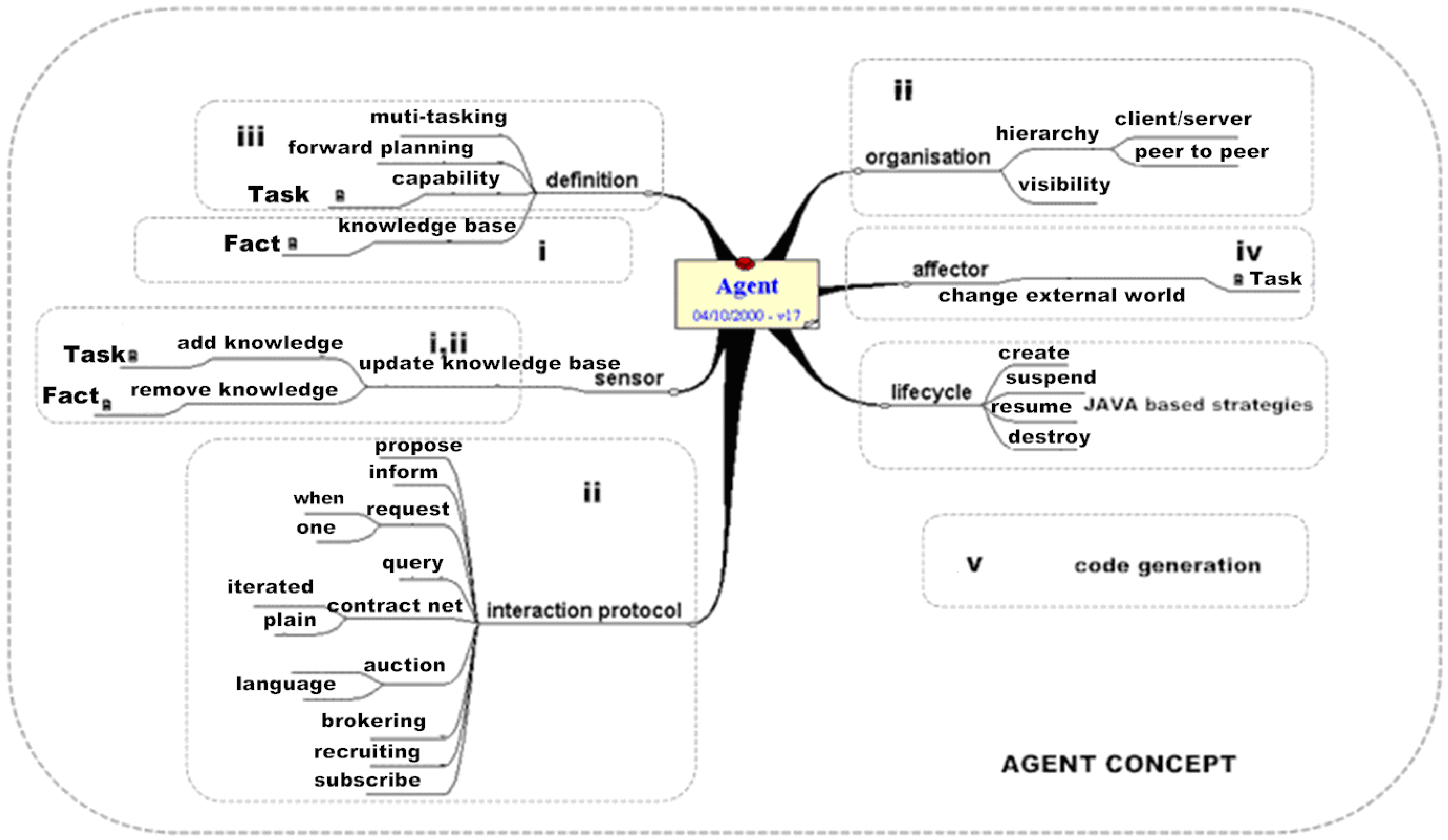
Figure 3.
Agent concept and steps of its realization.
Figure 3.
Agent concept and steps of its realization.
Section (I) To build agents using the ZEUS platform: to establish a MAS by ZEUS requires five steps—(i) ontology creation, (ii) agent creation, (iii) utility agent configuration, (iv) agent task configuration and (v) agent code generation. These steps are shown in
Figure 3 combined with the agent concept [
42]. Ontology is a set of declarative concepts within a particular application domain. ZEUS uses facts to represent these concepts. Facts are classified into two types, namely abstract and entity. As for microgrid control, most of facts used by agents are abstract facts. The agent creation process involves task agent definition (for each level of agents), task description (in this paper, we can ignore this part), agent organization (in a reactive manner) and coordination (Foundation for Intelligent Physical Agent [
43] compliant protocols). In the utility agent configuration step, the name server and the facilitator as well as the visualizer are configured. The three utility agents are default agents provided by ZEUS. Task agent configuration step enables the runtime parameters of the task agents to be specified and provides interface for task agents to link to external control programs or java by which specific control algorithms are achieved. Finally, the code generator can be invoked and agent source code automatically generated. We list the major facts used in the MAS in
Table 2 below.
Table 2.
Key facts in the hierarchical MAS.
Table 2.
Key facts in the hierarchical MAS.
| Facts | Value |
|---|
| Collection Method | Polling/CDT |
| Number of s | 2 |
| Power Notification | True/False |
| Island mode | True/False |
| DER Power Output | 50kW |
| DER Breaker | On/Off |
| Critical Loads | 50kW |
| Non-critical Loads | 12.5kW |
| LV Grid Power Output | 40MW |
| LV Grid Breaker | On/Off |
| Critical Loads Breaker | On/Off |
| Non-critical loads Breaker | On/Off |
Section (II) To design a microgrid simulation circuit:
Figure 4 shows the microgrid simulation circuit established by the MATLAB/SIMULINK platform.
Figure 4.
Microgrid simulation circuit based on MATLAB/Simulink platform.
Figure 4.
Microgrid simulation circuit based on MATLAB/Simulink platform.
The circuit is implemented on two PCs and the details are described in the next section. In
Figure 4, the function of each module shown is as follows. (1) DER with 50 kW capacity; (2) the inverter to achieve conversion from DC to 220 V AC; (3) LC filter network, used to reduce harmonic interference; (4) the pulse width modulator, used to control the gate
g of inverter to output stable AC; (5) the control interface for receiving control signals from terminal-level agents (6) the isolation transformer; (7) the load circuit breaker; (8) the network interface for connecting with terminal-level agents used to monitor and control microgrid; (9) the critical loads with 50 kW, and the load breakers are connected; (10) the non-critical loads with 12.5 kW, connected with load breakers; (11) LV grid breaker; (12) distribution transformers; (13) outage simulator of LV grid; (14) LV grid loads; (15) 10 kV LV grid; B1, B2, B3 for the three-phase voltage/current meter.
Figure 5.
The framework of the hierarchical MAS for microgrid control.
Figure 5.
The framework of the hierarchical MAS for microgrid control.
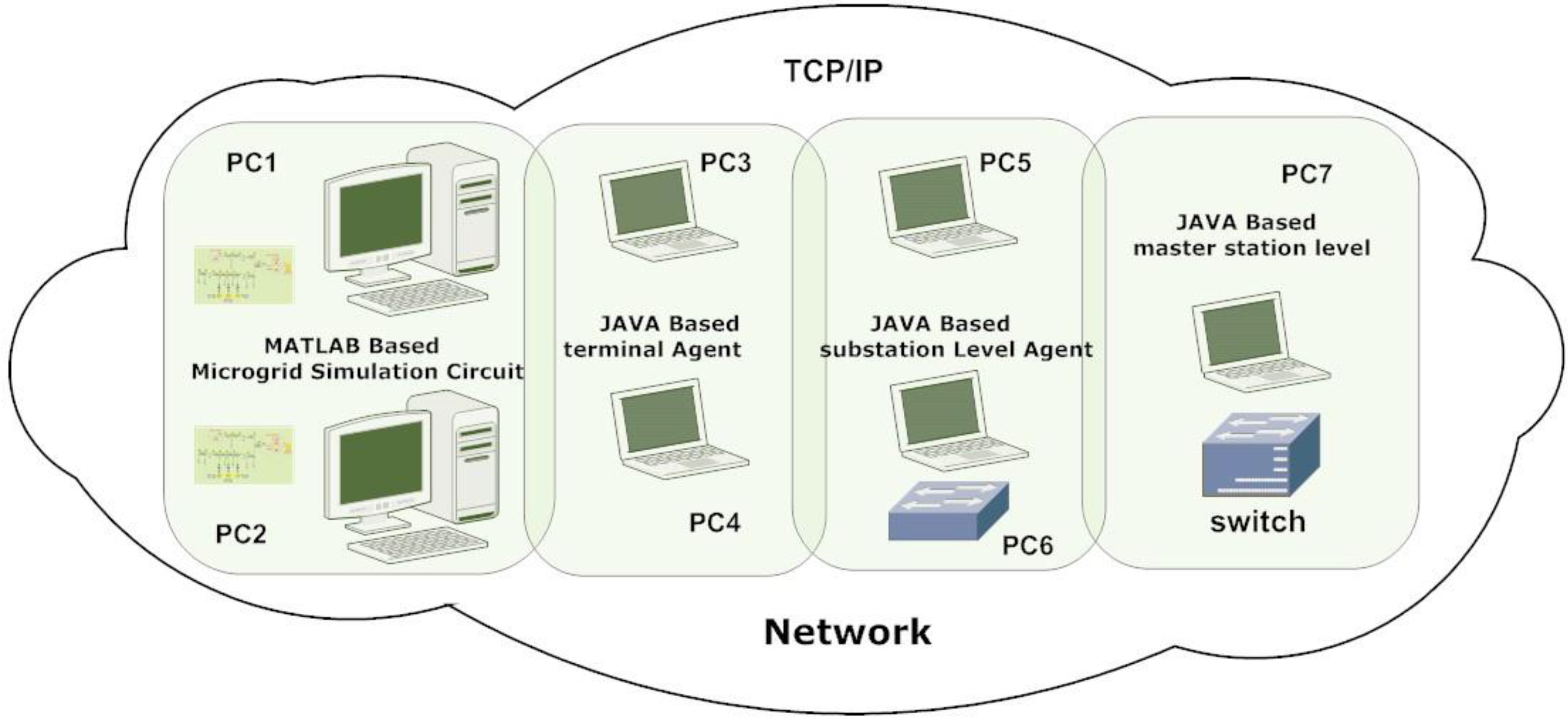
Section (III) TCP/IP Connection between MAS and microgrid simulation circuit: In order to demonstrate the hierarchical MAS based control system, we have built a communication and control framework as shown in
Figure 5. Two microgrid simulation circuits with photovoltaic and wind energy generators are simulated at PC1 and PC2; the Java-based terminal-level agents (DER, Load and LV substation agents) are implemented at PC3 and PC4 in order to control the simulation circuits at PC1 and PC2 at the component level; terminal-level agents collect information from the circuit and send it to the substation level agents implemented at PC5 and PC6 for an optimal decision; the master station level agents at PC7 gather the running state from both the microgrids through substation level agents. PC1-PC7 are connected with each other using TCP/IP sockets, and different socket ports are used to distinguish the different applications between the various agents. Microgrid flexibility can be achieved by allowing its operation under two modes. One is grid-connected mode, in which the microgrid is connected to a LV substation, being either partially supplied from it or injecting some amount of power into it. The other is island mode, in which the microgrid operates autonomously (as in physical islands) when the disconnection from the upstream LV substation occurs. The microgrid islanding process may result from an intentional disconnection from the LV substation or from a forced disconnection (due to a fault in the LV substation). The simulation includes the seamless switching from grid-connected mode to island mode of the microgrid model at PC1 and the switching from island mode to grid-connected mode of the microgrid model at PC2. The microgrid at PC1 simulates the switching from grid-connected mode to island mode while an upstream outage is sensed by the terminal level agents at PC3. For microgrids running at PC2, MAS operates it to switch from grid-connected mode to island mode while the substation level agent at PC4 gets a notice of power supply from an outside power bureau; In order to prove the MAS can control different microgrids in real-time, an artificial outage for the microgrid at PC1 and a power supply notification for microgrid at PC2 occur at the same time. More details of the switching process are described in
Section 4. Real-time measurements from circuits at PC1 and PC2—including voltages, currents, status of circuit breakers, power produced by DERs and power consumption by critical and non-critical loads—are sensed and monitored by the terminal level agents at PC3 and PC4 and then are merged to master station level agents through substation level agents at PC5 and PC6 via TCP/IP networks. Detailed results are illustrated in
Section 4.
Section (IV) The inter-agent communication is implemented with each message communicated as a sequence of ASCII characters via point-to-point TCP/IP sockets. All the agents communicate using messages that obey the FIPA 1997 agent communication languages (ACL) specification which are based on speech act theory.
Figure 6 illustrates the hierarchical MAS and their interactions with each other. All levels of agents communicate with the database agent, which comprises the name server and the facilitator. In Zeus, the name server and the facilitator are collectively termed utility agents. All messaging exchanges among agents are established via the Transmission Control Protocol/Internet Protocol (TCP/IP).
Figure 6.
The inter-agent communication of hierarchical MAS.
Figure 6.
The inter-agent communication of hierarchical MAS.
In the hierarchical MAS for microgrids, the core communication process is described as follows: the initialization of the hierarchical MAS is performed by all levels of agents by notifying the database agent of their presence. This includes all agents notifying the name server of their names and IP addresses in order to update the name database; all agents notifying the facilitator of their abilities to the facilitator to fill its database with information regarding abilities of agents (1-3). After the initialization process, the agents start to interact with each other and with their environments or the microgrid components. As for the communication between terminal level agents, the LV substation agent receives measurements from the substation grid and issues the information to the DER agent and Load agents (6, 9). The Load agent receives power requirement information from the loads and sends a notification to the DER agent (5), and meanwhile updates the values of the corresponding facts—“Critical Loads” and “Non-critical Loads”. On the other hand, the DER agent receives power production information from the DER and meanwhile sends out this information to the load agent (4), to renew the value of the facts of “DER Power Output”. The load agent and the DER agent react to their environments according to rules predetermined by a user. While the microgrid runs in grid-connected mode, if an outage is detected, the LV substation agent sends out a notification signal to the load agent to close the non-critical load breaker (9) and change the state of the fact “LV Grid Breaker”. While the microgrid works at the island mode, the LV substation agent waits for the power supply notifications from substation level agents, if a notification comes, substation level agents notify the corresponding LV substation agent and meanwhile provide the power measurements (11) to update the value of the fact “LV Grid Power Output”. Terminal level agents send essential information to substation level agents for centralized control to solve an optimization problem and to minimize the various losses (10). The information is further sent to master station level agent for an overall schedule and decision-making process includes the management of power supply, bidding management and overall market policy,
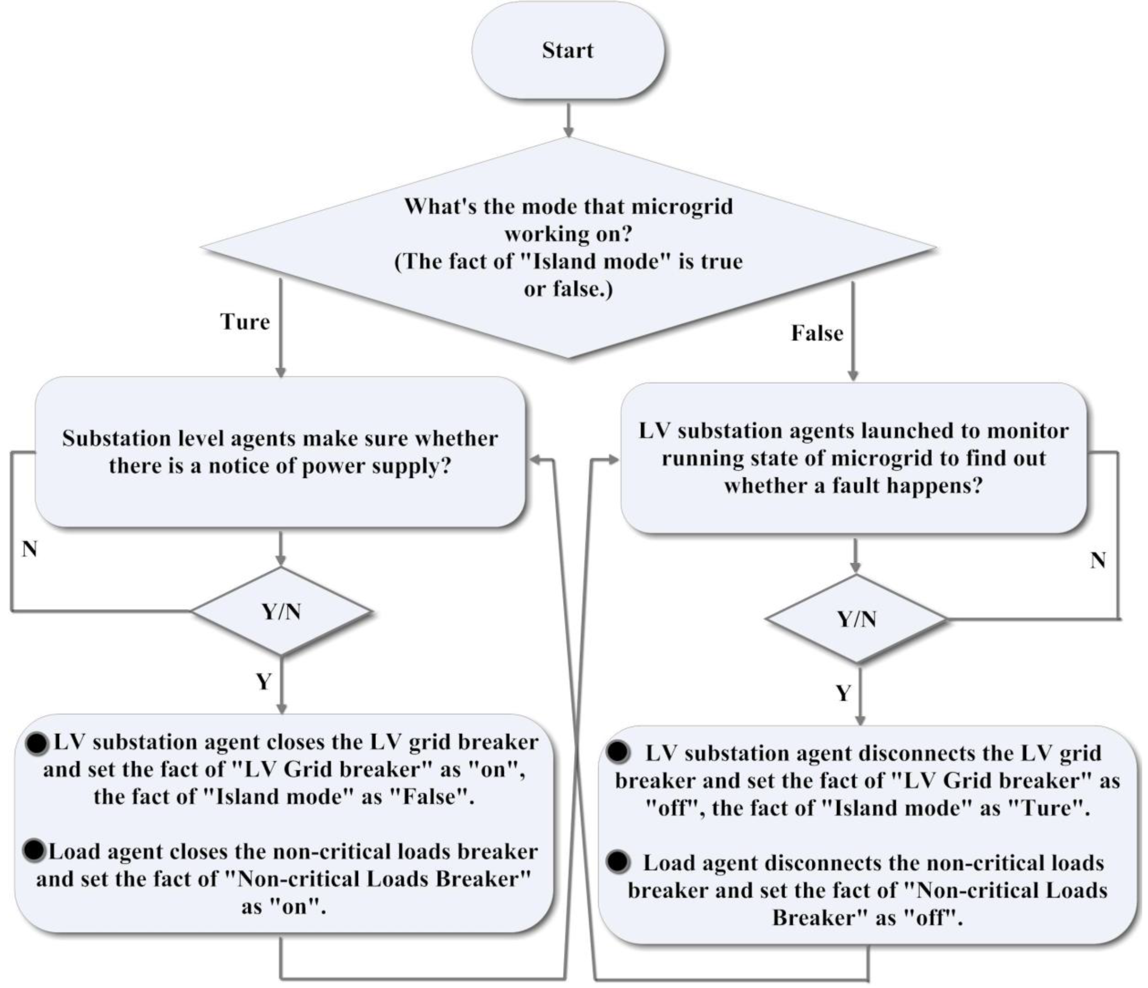
etc (12, 13). Note that the discussion above refers to interactions among agents in a single divisional district. More than one district can be created using the same collaborative diagram presented above. The overall flow chart of the MAS strategies is shown in
Figure 7 below.
Figure 7.
The flow chart of MAS strategies.
Figure 7.
The flow chart of MAS strategies.

 ,
, 

