Article

Assessment of the Effects of Flow Rate and Ionic Strength on the Performance of an Air-Cathode Microbial Fuel Cell Using Electrochemical Impedance Spectroscopy

1
School of Civil and Environmental Engineering, Georgia Institute of Technology, Atlanta, GA 30332, USA
2
Nuclear Sciences and Technology Division, Oak Ridge National Laboratory, Oak Ridge, TN 37831, USA
3
The University of Tennessee, Knoxville, TN 37996, USA
4
BioSciences Division, Oak Ridge National Laboratory, Oak Ridge, TN 37831, USA
*
Author to whom correspondence should be addressed.
Energies 2010, 3(4), 592-606; https://doi.org/10.3390/en3040592
Submission received: 5 January 2010 / Revised: 27 February 2010 / Accepted: 15 March 2010 / Published: 26 March 2010
(This article belongs to the Special Issue Fuel Cells)

Abstract

:
Impedance changes of the anode, cathode and solution were examined for an air-cathode microbial fuel cell (MFC) under varying conditions. An MFC inoculated with a pre-enriched microbial culture resulted in a startup time of less than ten days. Over this period, the anode impedance decreased below the cathode impedance, suggesting a cathode-limited power output. Increasing the anode flow rate did not impact the anode impedance significantly, but it decreased the cathode impedance by 65%. Increasing the anode-medium ionic strength also decreased the cathode impedance. These impedance results provide insight into electron and proton transport mechanisms and can be used to improve MFC performance.

1. Introduction

Microbial fuel cells (MFCs) have been demonstrated to generate electricity from a variety of carbon sources used as electron donors. Major efforts in MFC development are aimed at improving power density [1,2] and investigating issues associated with scale-up operations. In addition, studies focused on the removal of the membrane separating the anode and cathode of an MFC have been performed to explore techniques that can reduce MFC cost [3,4]. Multiple techniques have been employed to glean information regarding the processes that occur while an MFC generates electricity. For example, the current interrupt method was employed by Liang et al. [5] to estimate the internal resistance for MFCs of various designs. This technique was also utilized to study the internal resistance for stacked MFCs, with a total internal resistance as low as 3.9 ± 0.5 Ω [6]. However, a more detailed understanding of the MFC, especially of the phenomena occurring at the electrodes is desirable to allow improvements in MFC design and operation.
An effective tool for guiding optimization of MFCs is electrochemical impedance spectroscopy (EIS). Gomadam and Widner [7] have provided a summary of EIS techniques, including modeling approaches. He and Mansfeld [8] have described EIS analysis specifically for MFCs and how it can be used to understand the effects of various MFC parameters. EIS measurements allow the study of phenomena happening at the electrodes and within the membrane-solution region. Specific parameters related to mass transfer, charge transfer and reaction kinetics can be evaluated using the technique. EIS has been demonstrated to provide insight regarding the total internal resistance of an MFC [8,9,10]. Bode plots and Nyquist plots are both popular forms of displaying EIS data, especially to make estimates of the internal resistance. MFC EIS studies have focused on the effects of materials [9,11], operating conditions [12,28], or geometry [13,14,15] on impedance parameters and on power density. EIS has also been demonstrated by Ramasamy et al. [16] as a useful tool for the detection of extra-cellular mediators for bacteria that perform mediator-assisted electron transfer to the anode. These studies allow the relationship between power output and chemical, biological and physical processes to be studied. Such knowledge guides optimization efforts to improve MFC performance.
Conditions in the MFC anode are expected to significantly influence the output of a MFC. These conditions include carbon source, anode fluid composition, temperature, flow rate, etc. A soluble carbon source compared to a particulate one can significantly change the MFC power output [17]. Liu et al. [18] also studied the effects of temperature and ionic strength on the MFC internal resistance. For example, increasing the anode fluid ionic strength from 100 mM to 400 mM resulted in nearly a 100% increase in power density (from 720 mW/m2 to 1330 mW/m2). For the same increase in ionic strength, the internal resistance was observed to have decreased from 161 Ω to 79 Ω. This internal resistance includes all resistive components in the MFC.
MFCs offer a unique benefit in that electricity can be produced simultaneously with the removal of mixed organic contaminants in water, such as those found in municipal and food industry wastewaters. This application of MFCs is demonstrated by the many studies involving MFC power generation using various wastewaters [17,19,20,21].
In this work, we utilize EIS to study the effects of the anode fluid circulation rate and ionic strength on the power output and on various resistance mechanisms of an MFC. The design of this MFC has been shown to minimize the internal solution resistance and generate a power density as high as 345 W/m3 (3650 mW/m2) [22]. The goal of this study is to provide a better understanding of the relationship between the MFC performance and the operating parameters, in order to further improve its performance. For instance, understanding how the biocatalyst in the anode compartment of the MFC responds to various operating conditions can lead to improved operating conditions and also reveal characteristics of the behavior of different components of the MFC (anode, cathode and membrane) that can be further optimized. Stable, optimized operation over a long period of time is important for MFCs; thus an assessment of the MFC subsequent to a four-month period is also included.

2. Materials and Methods

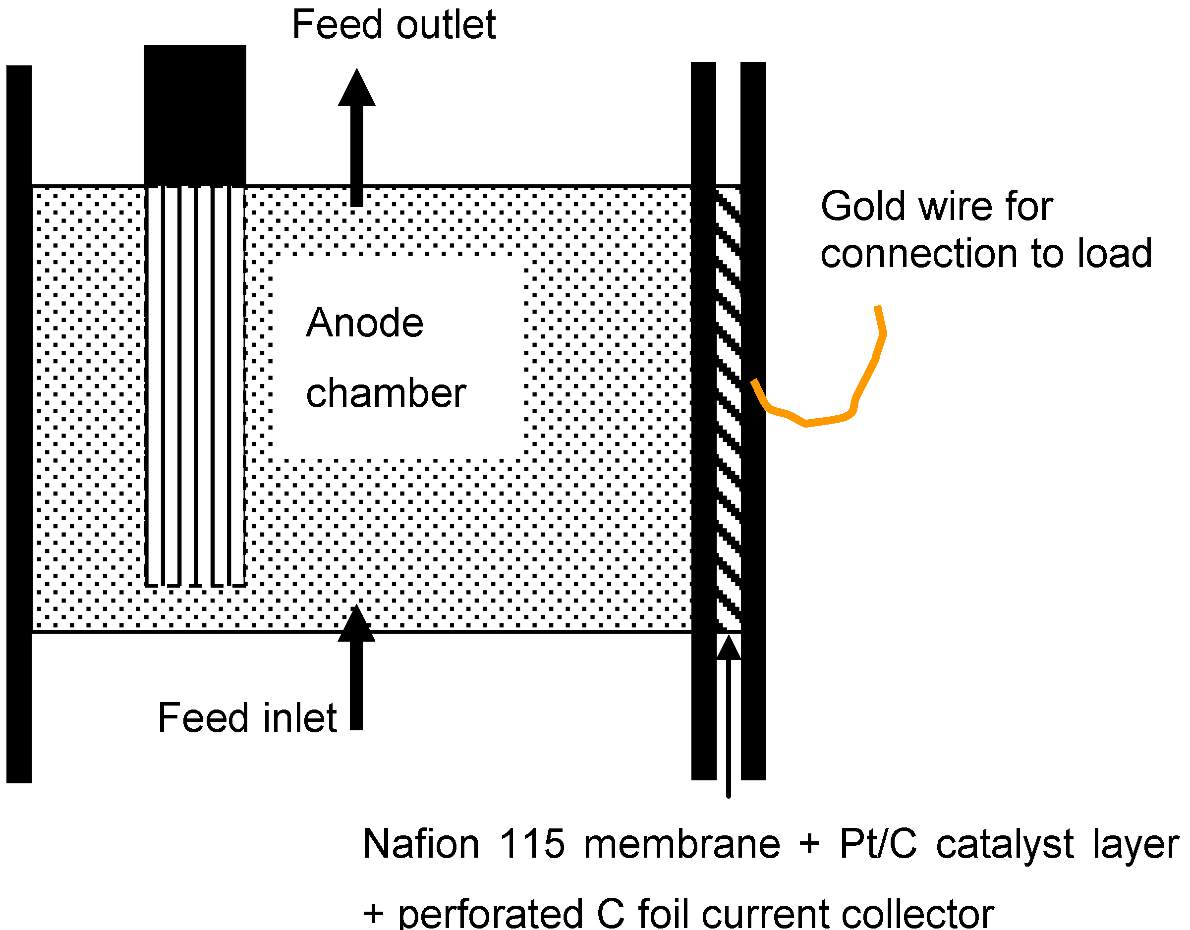
2.1. MFC design and operation

The inoculum for the MFC used in this work originated from a mature MFC fed with glucose and lactate. This inoculum was used in an effort to minimize startup time, as well as utilize a culture already optimized for exoelectrogenic bacteria. The characterization of the inoculum and the procedure used for its enrichment is described in detail elsewhere [4]. Throughout the operation of the MFC, the anode fluid was periodically replaced with fresh fluid to remove planktonic and dead cells. The MFC used in this study was comprised of a 4 cm diameter × 1.27 cm thickness anode chamber, Nafion 115 polymer electrolyte membrane (PEM) and a passive air cathode. The air cathode was made using a 2.54 cm × 2.54 cm carbon cloth deposited with 5 g/m2 Pt (Fuel Cell Store, San Diego, CA). This design of the MFC provided close contact between the anode and PEM and between the cathode and PEM in an effort to minimize electrode spacing. A perforated carbon foil (to allow airflow to the cathode catalyst layer) was used as a current collector and connected to a gold wire which served as the lead to connect to the external load. A carbon felt (Alfa Aesar, Ward Hill, MA) with a diameter of 4 cm and thickness of 1.27 cm served as a high surface area biofilm support and electrode. This anode had little dead volume and utilized a graphite rod as a current collector. Figure 1 is a schematic of the MFC design described here. The total volume of the anode compartment, lines and reservoir was approximately 230 mL. Voltage data were recorded with a 4-port DATAQ DI-158 USB-interface data acquisition system; in addition, power density analysis was performed using a Hewlett-Packard HP 3468B multimeter and variable-load resistor.

2.2. Electrochemical impedance spectroscopy

A Gamry Instruments series G 750 potentiostat/galvanostat/zero resistance ammeter was used to perform electrochemical impedance spectroscopy (EIS). For a description of EIS and how it is used to measure internal resistances in an electrochemical system, see the Gamry Instruments Application Note [23]. All measurements performed in this work were “whole cell” measurements; the EIS analysis was performed between the anode and cathode of the MFC. The cathode served as the working electrode, while the anode functioned as the reference and counter electrodes simultaneously. The applied AC signal for EIS was 0.001 V rms and had a frequency range from 100 kHz to 100 mHz. The signal amplitude was small because greater voltage (i.e., 0.010 V) resulted in the detachment of microbes from the anode. Such detachment disrupted the steady state operation of the MFC. Each measurement required approximately 8 minutes to complete. All EIS spectra were recorded when the MFC was generating electricity, thus under a 50 Ω external load. The only exceptions to this operation were the measurements made during the first four days of operation (at a load of 250 Ω). The 50 Ω load resulted in maximum or near-maximum power output for the MFC.
Figure 1. Schematic of the MFC. The peristaltic pump connected the anode chamber, via the feed inlet/outlet, to a 200 mL reservoir of anode fluid.
Energies 03 00592 g001

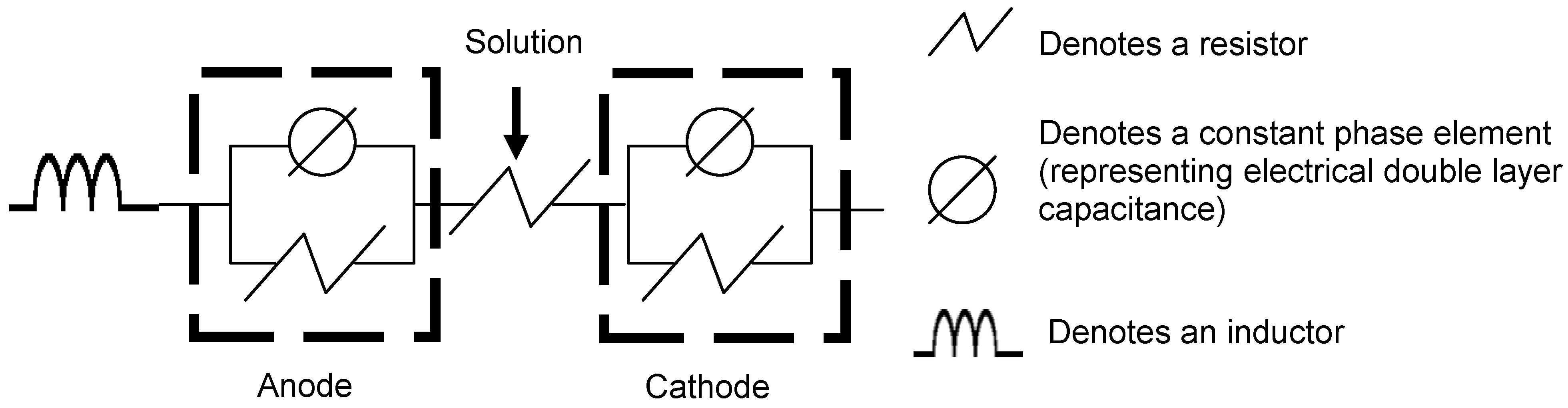
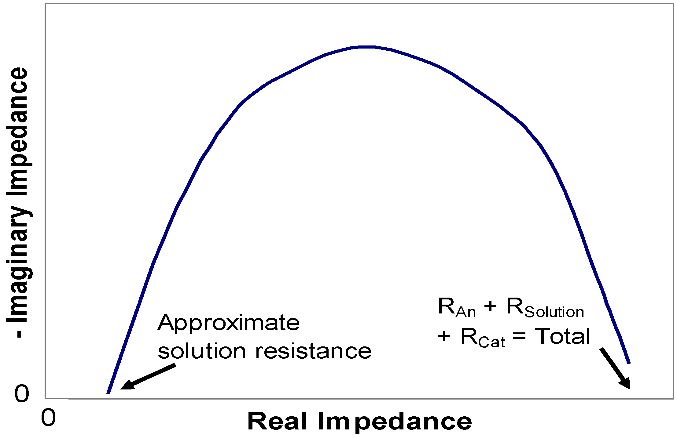
2.3. Equivalent circuit model

The ECM used in this work was comprised of two electrodes, each represented as a parallel resistor and constant phase element (CPE). These electrodes are separated by a resistor which represents a “solution resistance.” The solution resistance (termed Rsolution) includes the anode medium, PEM and cathode liquid film and is lumped together as a single parameter. The resistances at the electrodes represent a combined impedance (designated as RAn and RCat for anode and cathode, respectively) at the electrode surface. This potentially consists of charge transfer resistance, pore diffusion resistance, etc. However, those impedances were not broken down into individual impedances in this study, since it requires a highly complex model and the ability to study individual parameters via alteration of design and operational parameters, which was outside the scope of the present study. The CPE in each electrode represents electrical double layer capacitance that is the result of charged electrolyte species that accumulate near the charged surface of the electrode. Non-idealities, such as charge leakage, non-parallel plates and a non-planar electrode surface, have been proposed as reasons to use CPEs in place of capacitors [23]. Each CPE is comprised of two variable elements: a coefficient that represents capacitance and an exponent that accounts for the aforementioned non-idealities. An inductor is also included in the ECM in Figure 2. This inductor is considered a stray inductance resulting from the arrangement of the cable connecting the potentiostat to the MFC, thus not related to phenomena occurring within the MFC. Table 1 is a summary of the ECM variables.
Figure 2. Equivalent circuit model representing the MFC.
Energies 03 00592 g002
Table 1. Summary of components of ECM and associated regions of MFC.
AnodeResistorRAn
Constant phase element-coefficientYo_An
Constant phase element-exponentA_An
SolutionResistorRSolution
CathodeResistorRCat
Constant phase element-coefficientYo_Cat
Constant phase element-exponentACat
Nyquist and Bode plots were used for initial observations of the MFC performance. Nyquist plots allow estimation of Rsolution as the minimum point at which the data intersect the x-axis; the maximum point at which the data would intersect the x-axis corresponds to an estimate of the total MFC resistance. Figure 3 is an example of using the Nyquist plot for these estimations. The Nyquist plot does not, however, provide any indication of the distribution of resistance between the anode and cathode. Equivalent circuit modeling (ECM) was utilized to further explore the EIS results, specifically to determine the distribution of resistive and capacitive features in the operating MFC. Gomadam and Weidner [7] and He and Mansfeld [8] provide a description of the ECM technique for fuel cell EIS studies. The Simplex method was employed for fitting to allow delineation of the internal resistances and capacitances.
Figure 3. Typical Nyquist plot for an MFC. Notations indicate points for estimation of RSolution and total resistance.
Energies 03 00592 g003

2.4. MFC variables

The variables for MFC operation considered in this work focused on the anode. The effects of the anode fluid circulation rate and ionic strength were both studied. A Masterflex peristaltic pump (Cole-Parmer 7520-00) was used to circulate the anode medium between the anode compartment and a reservoir bottle. The volume of the anode compartment was 16 mL and the total volume of the fluid circulating was 230 mL. A calibration of the pump was performed to verify the settings for the desired flow rates. Flow rates ranging from 0 mL/min to 24 mL/min were explored in this work, and the shortest residence time of the fluid in the anode compartment was 40 s. The carbon source for the 0 mL/min experiment was the residual carbon in the anode compartment since no fresh anode fluid entered the compartment during the experiment. For all of the flow rate experiments, the anode fluid had a 0.2 g/day loading of glucose as a carbon source. Upon changing the flow rate, a stabilization time of approximately 90 minutes was observed. After this time, if the output voltage for the MFC was stable, EIS measurements were performed. Two EIS spectra were recorded for each flow rate condition to check reproducibility. For the anode fluid strength experiments, the 100% experiment used the 0.2 g/day carbon source loading at a recirculation flow rate of 7 mL/min. The undiluted anode fluid ionic strength was 0.37 M. Fresh fluid was diluted with distilled water to obtain 50%, 25% and 10% strength media, corresponding to ionic strengths of 0.19 M, 0.093 M, and 0.037 M, respectively. Upon completion of recording two EIS spectra for the 0.37 M condition, the anode fluid was replaced with 0.19 M fluid (50% dilution) and the MFC allowed to equilibrate overnight. The pH was monitored and maintained near 7.0 approximately two hours prior to performing EIS on the day following replacement of the anode fluid. This procedure was repeated for 0.093 M and 0.037 M conditions.

3. Results and discussion

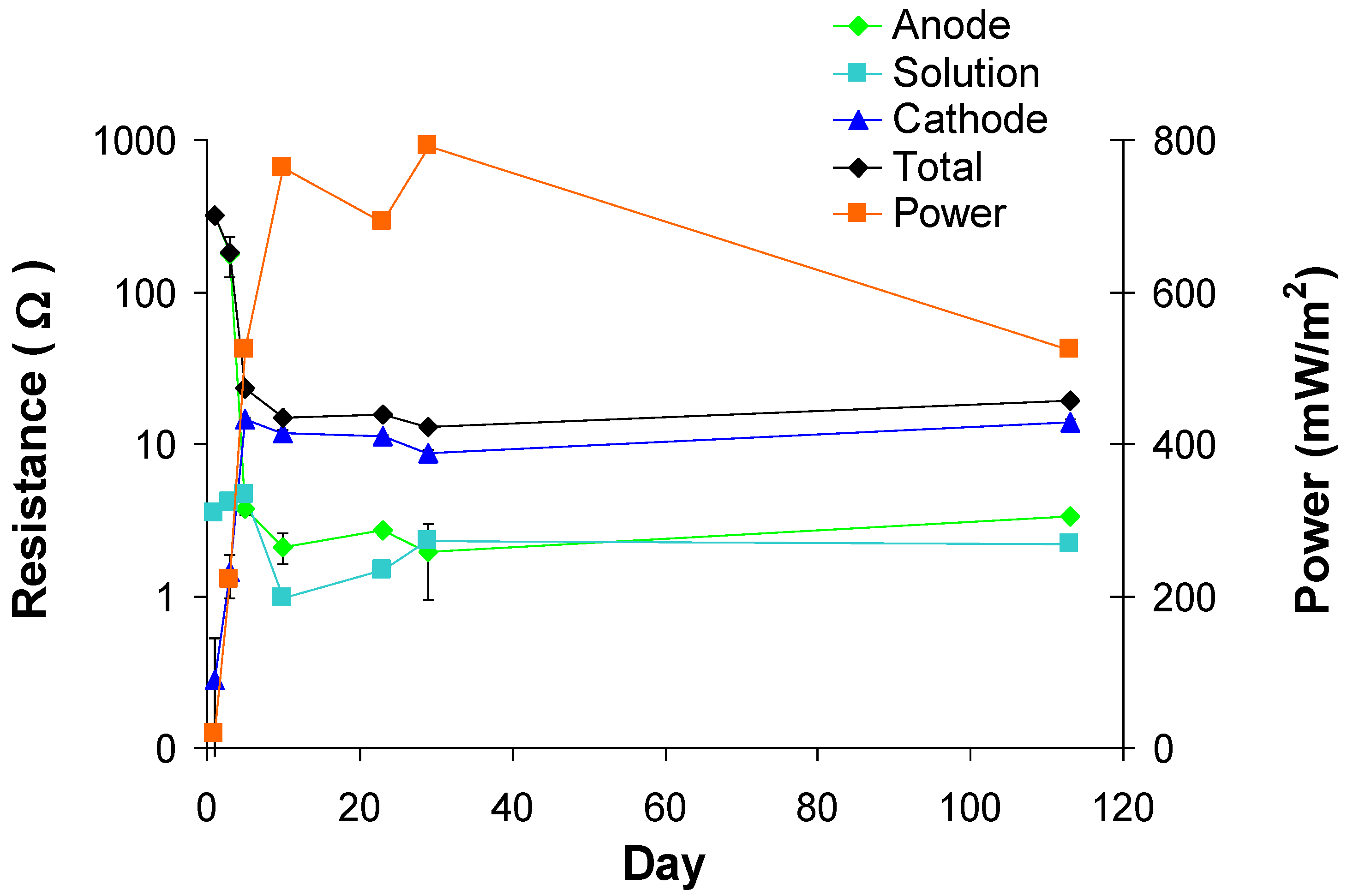
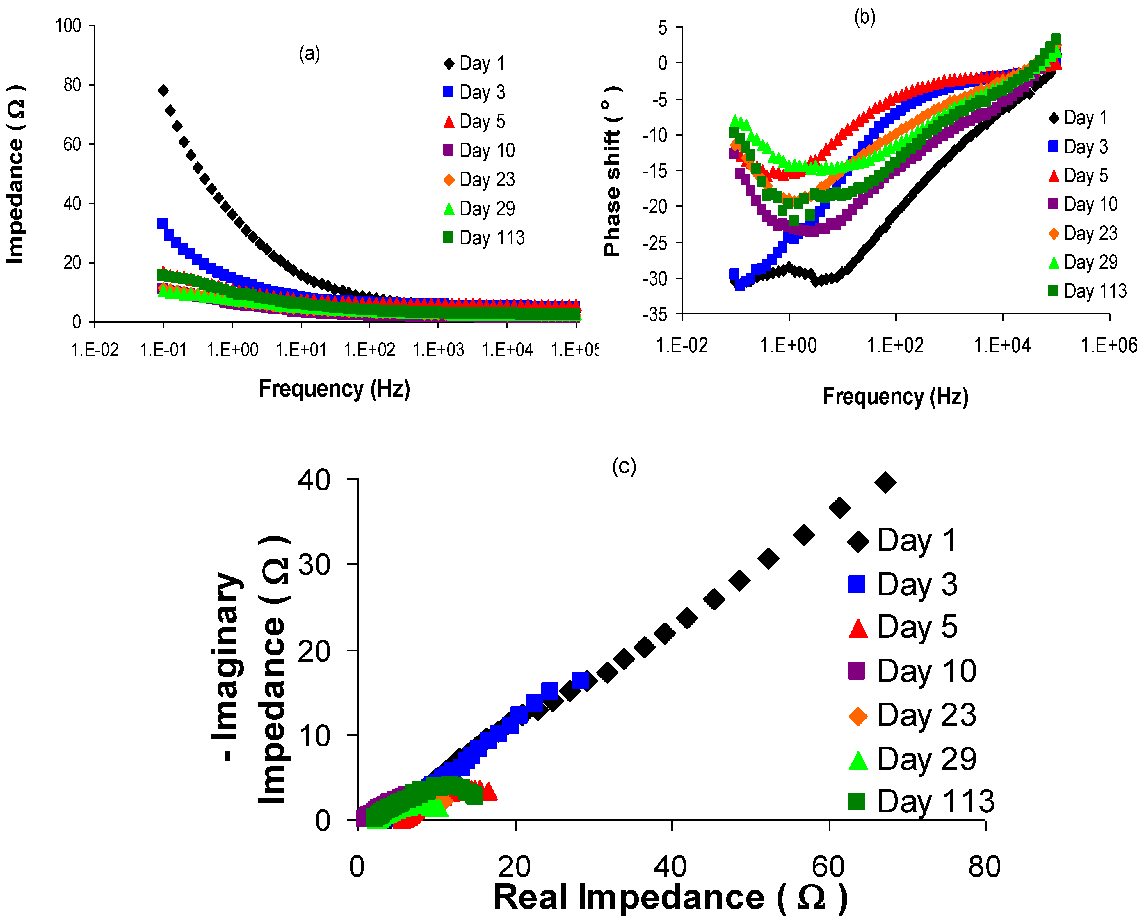
3.1. Model fitting and justification

The model used in this work consists of two parallel resistor-capacitor elements that represent the MFC electrodes separated by a single resistor that represents a lumped solution resistance. Figure 4 includes Bode and Nyquist plots of EIS data taken over the initial four months of MFC operation. These plots provided estimates of solution and total resistance for each measurement day. It can be seen in Figure 4a that all of the days had similar high frequency impedances; the highest frequency impedance is a good indicator of solution resistance. The total resistance, indicated by the low frequency impedance, decreased significantly between days 1 and 3. By day 5, the high frequency impedance had mostly stabilized. Over this same period, it can be seen in Figure 4b that the phase shift decreased from a peak of –33° to –25° and then further decreased to a minimum of –15° on day 29.
The Nyquist plots in Figure 4c clearly exhibit the reduction of total resistance. The measurements on day 1 and day 3 indicate that power density was not high enough to provide good estimates of total resistance. This is reflected in the uncertainty of the ECM fitting for these two days. However, the Nyquist plots do provide good total resistance estimates from day 5 onward. Even without performing equivalent circuit modeling, reductions in total resistance are apparent from the Nyquist plots. Also visible in Figure 4c is the effect of periodically replacing the anode fluid. This step was necessary to remove dead and planktonic cells. The solution resistance was observed to vary from approximately 1.3 Ω to as high as 6 Ω on the Nyquist plot.
Figure 4. (a) Bode plot showing impedance data for superimposition of EIS scans taken over 113 days. (b) Bode plot showing phase shift data for superimposition of EIS scans taken over 113 days. (c) Nyquist plot showing superimposition of EIS scans taken over 113 days.
Energies 03 00592 g004
Figure 5 shows the ECM analysis for EIS results collected over nearly four months of MFC operation. The total resistance decreased from 319 Ω on day 1 to a minimum of 13 Ω on day 29; the power output correspondingly increased from 19 mW/m2 to a maximum of 793 mW/m2. It is apparent in Figure 4 that RAn dominated the total MFC resistance in the early stages of anode biocatalyst growth. However, RAn decreased two orders of magnitude in resistance, from 315 ± 12 Ω to 3.75 ± 0.30 Ω, over the first five days of operation. RAn continued to decrease to 2.07 ± 1.01 Ω until day 10, where it remained stable for next 19 days. Analysis after about 4 months of operation indicated that the RAn was 3.30 ± 0.01 Ω on day 113. Over the first five days, RCat increased from 0.28 ± 0.25 Ω to approximately 15 ± 0.36 Ω and then decreased slightly over time until day 29. RCat increased over time to dominate the total resistance on day five and remained approximately 61% of the total resistance throughout the experiment. RSolution was relatively stable, varying between 0.96 ± 0.15 Ω and 4.66 ± 0.035 Ω; some variation is expected since the anode growth medium was periodically replaced as described above and this would affect time-dependent changes in anode medium ionic strength.
Figure 5. ECM analysis results for EIS data collected over 113 days of MFC operation.
Energies 03 00592 g005
The rapid decrease in RAn is attributed to the inoculum for the MFC originating from an already mature MFC. Previous results reported by Ramasamy et al. [24] indicate that anode resistance is initially high and then decreases over time as the biocatalyst acclimates to the MFC environment for exoelectrogenic behavior. The time for such changes to be observed for Ramasamy et al. was approximately three weeks, likely due to the inoculum originating from an anaerobic sludge. In the case of this study, however, the inoculum was from a previously-enriched MFC. As such, the microbial community did not undergo the period in which the bacteria acclimate and adapt to MFC conditions [22]. Also observed in this experiment was an increase in RCat rapidly from day 1 to 3, and then a relatively stable value for four months. Such an increase in RCat is possibly the result of a buildup of cations in the water layer between the PEM and cathode catalyst layer. It was observed over the course of the experiment that dry salt would accumulate on the cathode side, at the air-electrode interface. This salt layer indicates a high salt concentration in solution near the cathode active area which could impact the cathodic reaction or oxygen mass transfer and may be the reason for the cathodic limitations.
ECM calculations also allowed the delineation of capacitance terms for both the anode and cathode. Electrical double layer capacitance (EDL) forms as charged species in solution form a layer near the charged electrode. Since the capacitive behavior is expected to be non-ideal, a constant phase element (CPE) was used instead; use of a CPE involves addition of an exponent term (A, below) to the impedance response expression for an ideal capacitor. The impedance that results from such EDL behavior is described by Equation 1 [23]:
Z E D L = 1 Y o ( j ω ) A
In Equation 1, ZEDL is the impedance of the capacitor. Yo is the coefficient, jω is the complex frequency term, and A is an empirical factor that describes the degree of non-ideality for the capacitance. A can vary from 0 to 1, with 0 being completely non-ideal while a value of 1 indicates an ideal capacitance. Table 2 shows Yo and A data calculated for the anode and cathode over 113 days of operation. Yo_An refers to the coefficient for the anode, A_An is the exponent factor for the anode; cathode notation is similar.
Table 2. EDL factors calculated via ECM for data taken over 113 days.
5102329113
Yo_An0.1810.1220.0530.2250.116
A_An0.1240.3080.3970.6670.975
Yo_Cat0.0560.0680.0550.0580.038
A_Cat0.5570.5500.6830.5320.407
The coefficient for the anode (Yo_An) was relatively constant throughout the experiment. Yo_Cat was also relatively constant. Of interest is A_An, the exponent factor for the anode EDL. A_An increased from 0.124 on day 5 to 0.975, approaching unity, over the course of the experiment. This suggests that the anode EDL was highly non-ideal early in the experiment and then gradually approached ideal capacitive behavior. The cathode exponent, A_Cat; however, did not change significantly. The A factor for the anode was the only capacitance-related parameter that changed by any significant degree during the four-month time span. This indicates that the growth of the biofilm affects capacitive impedance of the electrode, in addition to the resistive component. Additionally, the time period over which A_An changes is much larger than the time period over which the resistive component changes took place.

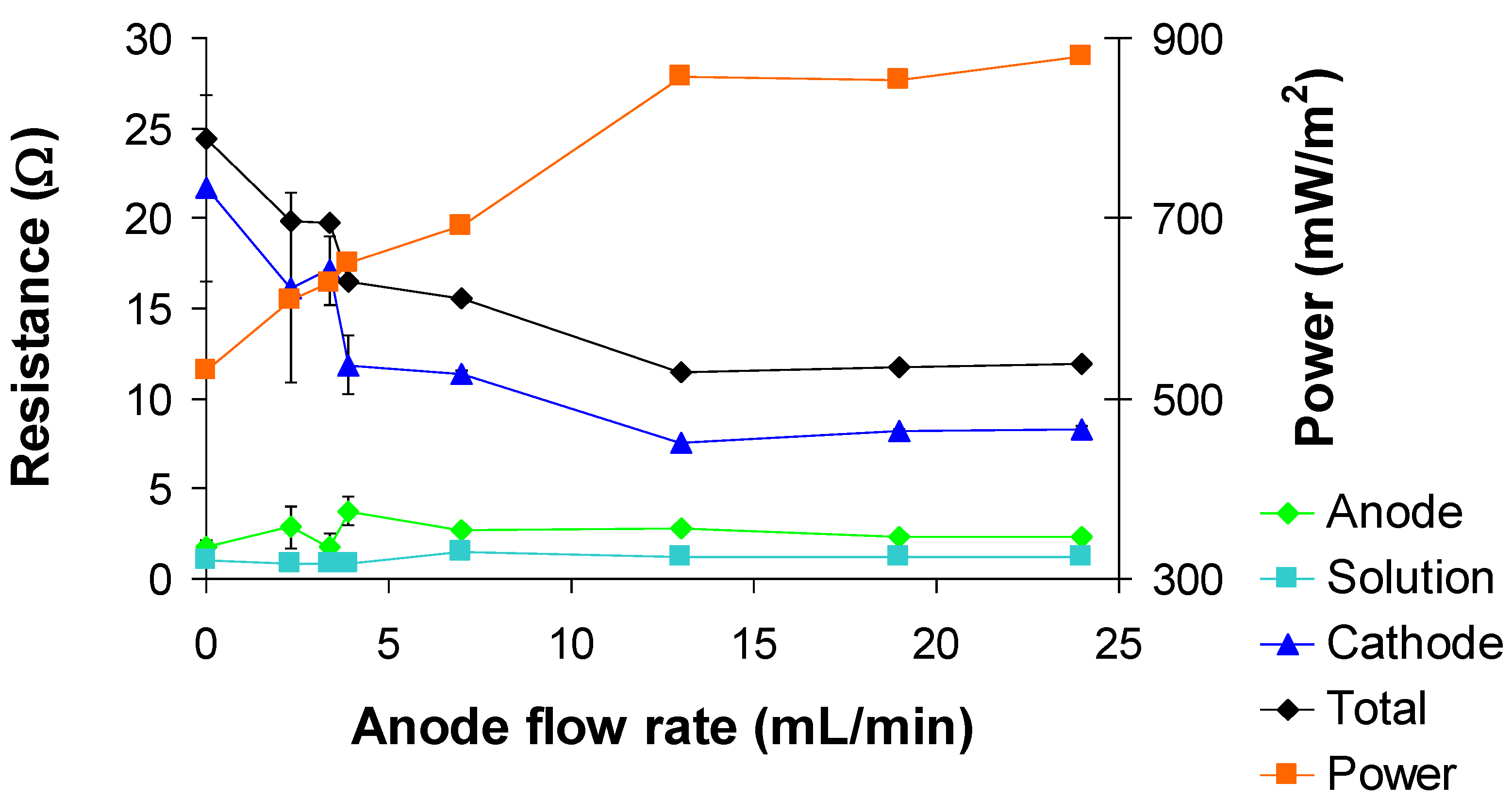
3.2. Effect of anode circulation flow rate

The flow rate through the anode chamber varied from 0 ml/min up to 24 mL/min. Figure 6 shows ECM results for the EIS measurements performed over the range of anode circulation rates. The total resistance for the MFC decreased from 24.5 Ω to a minimum of 7.51 Ω as the flow rate increased from 0 mL/min to 13 mL/min. The power output correspondingly rose from a minimum of 530 mW/m2 to 879 mW/m2. Maximum power and minimum resistance occurred at 13 mL/min, and a slight increase in resistance, with corresponding decrease in power, occurred as the flow rate increased to 24 mL/min. RAn over the range of flow rates was relatively stable, varying from 1.74 ± 0.38 Ω at 0 mL/min to a maximum of 3.77 ± 0.78 Ω at 3.9 mL/min. RSolution was observed to remain relatively unchanged throughout the series of flow rates explored here, varying between 0.846 ± 0.005 Ω and 1.48 ± 0.001Ω. RCat changed the most over the course of flow rates studied here. At 0 mL/min, RCat was 21.7 ± 0.2 Ω and decreased to a minimum of 7.51 ± 0.061 Ω at 13 mL/min before slightly increasing up to 8.31 ± 0.19 Ω at 24 mL/min.
Figure 6. ECM analysis results for EIS data while varying anode fluid flow rate.
Energies 03 00592 g006
The experiments investigating the effects of anode medium circulation rate were performed on days 23 and 24 after inoculation of the MFC. The impedance data for the MFC over time also demonstrated that the anode was not the limiting factor. As indicated earlier, the major changes in power density and impedance occurred within the first 10 days. Thus, when the experiments varying flow rate were conducted, the growth of the exoelectrogenic microbial culture in the anode had reached a steady state. RCat was therefore the dominant resistance among the various MFC components. The anode microbial culture used in this study was enriched under continuous flow conditions and with periodic medium replacement. As such, the electricity production was potentially dominated by conductive electron transfer mechanisms occurring within the biofilm. Direct electron transfer via biological nanowires has been suggested as one of the mechanisms for electron transfer within MFCs [21]. If direct electron transfer is assumed to be taking place within the biofilm, the conditions outside the biofilm would have less effect on the charge transfer between the bacteria and electrode, as opposed to if mediated electron transfer was occurring. The exception to this would be if the flow rate was so great that the biofilm was damaged. However, there was no evidence of biofilm removal under the conditions studied. It should also be noted that even though the anode circulation flow rate was varied, the delivery of glucose to the anode continued at a constant 0.2 g/day. The variation of the anode fluid recirculation rate resulted in a change in the glucose concentration within the anode; however, RAn did not change appreciably with changes in flow rate (Figure 6), indicating that glucose availability was not a problem.
The cathode resistance, RCat, was observed to decrease by 63% as the anode flow rate increased from 0 mL/min to 24 mL/min. As flow rate through the anode increased, mixing in the anode was expected to have improved, as well, due to convection. The half reaction occurring at the cathode consumed protons, which are transported to the cathode from the anode side through the membrane. In addition to providing glucose to the anode, circulation of the anode medium reduced the likelihood of proton depletion (or ‘protonated species’ via the buffer) in the anode chamber. Thus, increasing flow rate would mean higher, consistent proton concentration as well as improved mixing, which may have helped reduce pH polarization and improved proton availability at the cathode. With improved proton transport to the cathode, the reaction rate at the cathode can increase, thus resulting in a reduced resistance. The cathode resistance includes charge transfer resistance, double layer resistance and potentially diffusion resistance. The relationship between charge transfer resistance and reaction rate can be described by Equation 1, below:
R C a t = R T n F I E x c h a n g e
In Equation 2, R is the ideal gas constant (J/mol-k), T is temperature (K), n refers to the number of electrons occurring in the charge transfer reaction, F is the Faraday constant (C/mol), and Iexchange is the exchange current density. Exchange current density is the rate at which electrons are transferred between an electrode and electrolyte [25]. This is related to the rate at which protons, electrons and oxygen combine to form water, since this is the only sink of electrons present at the cathode. Several studies on the effect of cathode conditions on MFC performance have been reported and it has been shown that the cathodic reaction can be a limiting factor under certain conditions. We assume here that the resistance at the cathode is dominated by charge transfer resistance of the reaction occurring at the cathode. Thus, if RCat is observed to decrease, there is an attendant increase in IExchange, which can result from an increase in the rate at which protons reach the active sites in the cathode.

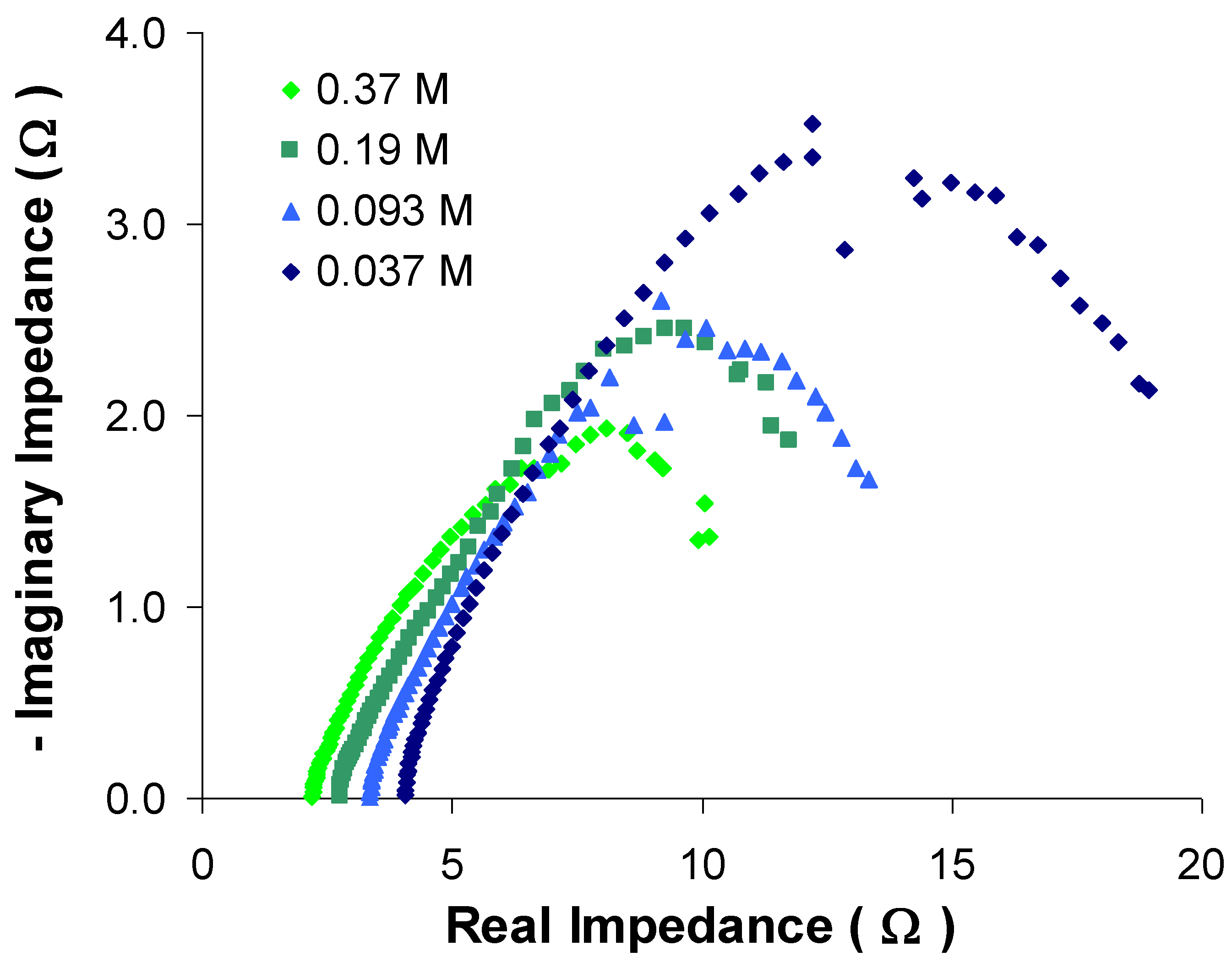
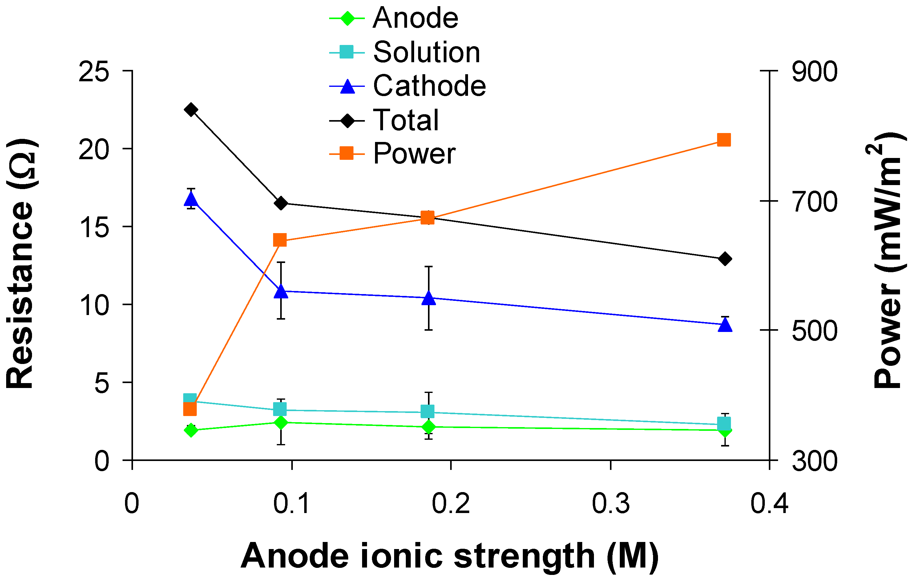
3.3. Effect of anode fluid ionic strength

The experiments focused on anode fluid ionic strength included fluid strengths ranging from 0.37 M (undiluted) to 0.037 M (10% of original concentration). Figure 7 is a Nyquist plot including results for EIS spectra for each anode fluid ionic strength. It is apparent that approximate total resistance decreased as anode fluid ionic strength increased. In addition, a reduction in solution resistance is visible as the anode fluid strength increased. It can be seen in Figure 8 that a general trend of reduced total resistance and increased power output occurred as the anode fluid ionic strength increased. The total resistance decreased from 22.5 Ω at 0.037 M to 13.0 Ω at 0.37 M. The power output was observed to increase from 378 mW/m2 to a maximum of 793 mW/m2 over the same range. RAn was 1.96 ± 0.24 Ω at 0.037 M and remained nearly unchanged, increasing only to a maximum of 2.45 ± 1.48 Ω at 0.093 M and then decreasing back down to 1.96 ± 1.01 Ω at 0.37 M. RSolution continuously decreased from 3.79 ± 0.10 Ω at 0.037 M down to 2.27 ± 0.16 Ω at 0.37 M; this is a reduction of approximately one third. RCat also decreased markedly, from 16.8 ± 0.64 Ω at 0.037 M to 8.72 ± 0.46 Ω at 0.37 M, which is a much larger reduction than the solution resistance in terms of absolute values, indicating the importance of cathode impedance in MFC performance.
The experiments investigating the effect of anode medium ionic strength were performed between days 29 and 36. This, as indicated by Figure 5, is in the period when RAn has decreased to a steady value below that of RCat, and similar to RSolution. The relatively constant values of RAn for varying anode fluid ionic strength indicate that the electron transfer from the microbes to the electrodes is not dependent on any charged species present in the nutrient medium. So long as enough nutrients are present to not limit microbial metabolism, changes to the anode medium will have little effect on the anode behavior. The reduction in Rsolution is expected, considering increased ionic strength increases conductivity of an electrolyte. Dlugolecki et al. [26] demonstrated that the membrane resistance of a cation-exchange membrane was reduced by up to 93% when the ionic strength was increased by a factor of 20. The salt used in their experiments was NaCl, but similar behavior should be observed for a Nafion membrane with the anode fluid in this work. The reduction in RCat is likely attributable to increased proton transport to the cathode, similar to that as observed for increasing anode fluid circulation flow rate (described above).
Figure 7. Nyquist plot of varying anode fluid strength experiments.
Energies 03 00592 g007
Figure 8. ECM analysis results for EIS data while varying anode fluid strength.
Energies 03 00592 g008
It was demonstrated by Aaron et al. [27] that changes to one electrode side of a polymer electrolyte membrane fuel cell can have measureable effects on the other side. Thus, the finding that changes to the anode of an MFC can result in effects in the cathode is reasonable. In these experiments, it was observed that RCat actually responded more strongly to changes in the anode than did RAn. Such behavior, observed for changes to both the anode fluid flow rate and strength, is likely due to a combination of a stabilizing effect of the biofilm and a limiting cathode starved for protons.

4. Conclusions

Experiments were performed that utilized EIS to investigate internal resistance mechanisms in a MFC. Over the first 10 days of operation, the anode resistance was observed to have decreased below that of the cathode. Such a short startup time is attributed to the inoculum coming from an operating MFC. This time period is much lower than the time taken by MFCs inoculated with samples from anaerobic sludge reactors or the environment. The total resistance was dominated in the anode during the first five days, at which time the anode was the limiting step. It was also observed via EIS that the A factor for the anode, which represents the non-ideality of the capacitive behavior changed over time and approached that of an ideal capacitor. Operational parameters included anode fluid circulation flow rate and anode fluid ionic strength. It was observed that increased anode fluid flow rate and ionic strength both contributed to increased power density for the MFC. EIS analysis showed that the power density increased largely due to reductions in cathode impedance. In addition, the anode impedance was observed to be only slightly affected by changes in anode fluid flow rate or ionic strength. This suggests that cathode limitations can be partially mitigated by changes in the anode operating conditions. Such changes are potentially due to an improved rate of proton transport to the cathode, increasing the reaction rate at the cathode. An inter-dependence of each component of the MFC on the other components was also illustrated in this work. Assessment of the EIS parameters of the MFC at the end of one month and four month operational periods indicated that the slight reduction in power output over time corresponded with an increase in the impedance of the MFC components.

Acknowledgments

This research was sponsored by the Laboratory Directed Research and Development Program of Oak Ridge National Laboratory (ORNL), managed by UT-Battelle, LLC, for the U. S. Department of Energy under Contract No. DE AC05-00OR22725 and by the American Chemical Society, Petroleum Research Fund, Green Chemistry Initiative through a grant to Georgia Institute of Technology.

References and Notes

  1. Borole, A.P.; Hamilton, C.Y.; Vishnivetskaya, T.A.; Leak, D.; Andras, C.; Morrell-Falvey, J.; Davison, B.H.; Keller, M. Integrating engineering design improvements with exoelectrogen enrichment process to increase power output from microbial fuel cells. J. Power Sources 2009, 191, 520–527. [Google Scholar] [CrossRef]
  2. Borole, A.P.; Hamilton, C.Y.; Vishnivetskaya, T.A.; Leak, D.; Andreas., C. Improving power production from acetate-fed microbial fuel cells via enrichment of exoelectrogenic organisms in continuous flow systems. Biochem. Eng. J. 2009, 48, 71–80. [Google Scholar] [CrossRef]
  3. Fan, Y.; Hu, H.; Liu, H. Enhanced coulombic efficiency and power density of air-cathode microbial fuel cells with an improved cell configuration. J. Power Sources 2007, 171, 348–354. [Google Scholar] [CrossRef]
  4. Liu, H.; Cheng, S.; Huang, L.P.; Logan, B.E. Scale-up of membrane-free single-chamber microbial fuel cells. J. Power Sources 2008, 179, 274–279. [Google Scholar] [CrossRef]
  5. Liang, P.; Huang, X.; Fan, M.Z.; Cao, X.X.; Wang, C. Composition and distribution of internal resistance in three types of microbial fuel cells. Appl. Microbiol. Biotechnol. 2007, 77, 551–558. [Google Scholar] [CrossRef] [PubMed]
  6. Aelterman, P.; Rabaey, K.; Pham, H.T.; Boon, N.; Verstraete, W. Continuous electricity generation at high voltages and currents uding stacked microbial fuel cells. Environ. Sci. Technol. 2006, 40, 3388–3394. [Google Scholar] [CrossRef] [PubMed]
  7. Gomadam, P.M.; Weidner, J.W. Analysis of electrochemical impedance spectroscopy in proton exchange membrane fuel cells. Int. J. Energy Res. 2005, 29, 1133–1151. [Google Scholar] [CrossRef]
  8. He, Z.; Mansfeld, F. Exploring the use of electrochemical impedance spectroscopy (EIS) in microbial fuel cell studies. Energy Environ. Sci. 2009, 2, 215–219. [Google Scholar] [CrossRef]
  9. Manohar, A.K.; Mansfeld, F. The internal resistance of a microbial fuel cell and its dependence on cell design and operating conditions. Electrochim. Acta 2009, 54, 1664–1670. [Google Scholar] [CrossRef]
  10. He, Z.; Huang, Y.L.; Manohar, A.K.; Mansfeld, F. Effect of electrolyte pH on the rate of the anodic and cathodic reactions in an air-cathode microbial fuel cell. Bioelectrochemistry 2008, 74, 78–82. [Google Scholar] [CrossRef] [PubMed]
  11. Ouitrakul, S.; Sriyudthsak, M.; Charojrochkul, S.; Kakizono, T. Impedance analysis of bio-fuel cell electrodes. Biosens. Bioelectron. 2007, 23, 721–727. [Google Scholar] [CrossRef] [PubMed]
  12. Torres, C.I.; Lee, H.S.; Rittmann, B.E. Carbonate species as OH- carriers for decreasing the pH gradient between cathode and anode in biological fuel cells. Environ. Sci. Technol. 2008, 42, 8773–8777. [Google Scholar] [CrossRef] [PubMed]
  13. Manohar, A.K.; Bretschger, O.; Nealson, K.H.; Mansfeld, F. The use of electrochemical impedance spectroscopy (EIS) in the evaluation of the electrochemical properties of a microbial fuel cell. Bioelectrochemistry 2008, 72, 149–154. [Google Scholar] [CrossRef] [PubMed]
  14. He, Z.; Wagner, N.; Minteer, S.D.; Angenent, L.T. An upflow microbial fuel cell with an interior cathode: Assessment of the internal resistance by impedance spectroscopy. Environ. Sci.Technol. 2006, 40, 5212–5217. [Google Scholar] [CrossRef] [PubMed]
  15. You, S.J.; Zhao, Q.L.; Zhang, J.; Liu, H.; Jiang, J.Q.; Zhao, S.Q. Increased sustainable electricity generation in up-flow air-cathode microbial fuel cells. Biosens. Bioelectron. 2008, 23, 1157–1160. [Google Scholar] [CrossRef] [PubMed]
  16. Ramasamy, R.P.; Gadhamshetty, V.; Nadeau, L.; Johnson, G.R. Impedance spectroscopy as a tool for non-intrusive detection of extracellular mediators in microbial fuel cells. Biotechnol. Bioeng. 2009, 104, 882–891. [Google Scholar] [CrossRef] [PubMed]
  17. Borole, A.P.; Hamilton, C.Y. Energy production from food industry wastewaters using bioelectrochemical cells. In Emerging Environmental Technologies; Vishal, Shah, Ed.; Springer: Dordrecht, the Netherlands, 2010; Volume II, pp. 97–113. [Google Scholar]
  18. Liu, H.; Cheng, S.A.; Logan, B.E. Power generation in fed-batch microbial fuel cells as a function of ionic strength, temperature, and reactor configuration. Environ. Sci. Technol. 2005, 39, 5488–5493. [Google Scholar] [CrossRef] [PubMed]
  19. Feng, Y.; Wang, X.; Logan, B.E.; Lee, H. Brewery wastewater treatment using air-cathode microbial fuel cells. Environmental Biotechnology, 2008, 78, 873–880. [Google Scholar] [CrossRef]
  20. Rosenbaum, M.; Zhao, F.; Quaas, M.; Wulff, H.; Shroder, U.; Scholz, F. Evaluation of catalytic properties of tungsten carbide for the anode of microbial fuel cells. Appl. Catal. B. 2007, 74, 262–270. [Google Scholar]
  21. Logan, B.E.; Hamelers, B.; Rozendal, R.; Schroder, U.; Keller, J.; Freguia, S.; Aelterman, P.; Verstraete, W.; Rabaey, K. Microbial fuel cells: Methodology and technology. Environ. Sci. Technol. 2006, 40, 5181–5192. [Google Scholar] [CrossRef] [PubMed]
  22. Borole, A.P.; Hamilton, C.Y.; Aaron, D.S.; Tsouris, C. Investigating microbial fuel cell bioanode performance under different cathode conditions. Biotechnol. Prog. 2009, 25, 1630–1636. [Google Scholar] [PubMed]
  23. Gamry Instruments Application Note. Basics of Electrochemical Impedance Spectroscopy. 2006.
  24. Ramasamy, R.P.; Ren, Z.Y.; Mench, M.M.; Regan, J.M. Impact of initial biofilm growth on the anode impedance of microbial fuel cells. Biotechnol. Bioeng. 2008, 101, 101–108. [Google Scholar] [CrossRef] [PubMed]
  25. Orazem, M.E.; Tribollet, B. Electrochemical Impedance Spectroscopy; John Wiley and Sons: Hoboken, NJ, USA, 2008. [Google Scholar]
  26. Dlugolecki, P.; Anet, B.; Metz, S.J.; Nijmeijer, K.; Wessling, M. Transport limitations in ion exchange membranes at low salt concentrations. J. Membr. Sci. 2010, 346, 163–171. [Google Scholar] [CrossRef]
  27. Aaron, D.; Yiacoumi, S.; Tsouris, C. Effects of proton-exchange membrane fuel-cell operating conditions on charge transfer resistances measured by electrochemical impedance spectroscopy. Sep. Sci.Technol. 2008, 43, 2307–2320. [Google Scholar] [CrossRef]
  28. Borole, A.P.; Aaron, D.; Hamilton, C.Y.; Tsouris, C. Understanding long-term changes in microbial fuel cells via electrochemical impedance spectroscopy. Environ. Sci. Technol. 2010. [Google Scholar] [CrossRef]

