Gasification Processes Old and New: A Basic Review of the Major Technologies

NETL-US DOE, PO Box 880 Morgantown, WV 26507, USA
Energies 2010, 3(2), 216-240; https://doi.org/10.3390/en3020216
Submission received: 8 January 2010
/
Accepted: 3 February 2010
/
Published: 23 February 2010
(This article belongs to the Special Issue Coal Gasification and Liquefaction)
Abstract
:This paper has been put together to provide a single source document that not only reviews the historical development of gasification but also compares the process to combustion. It also provides a short discussion on integrated gasification and combined cycle processes. The major focus of the paper is to describe the twelve major gasifiers being marketed today. Some of these are already fully developed while others are in various stages of development. The hydrodynamics and kinetics of each are reviewed along with the most likely gas composition from each of the technologies when using a variety of fuels under different conditions from air blown to oxygen blown and atmospheric pressure to several atmospheres.
1. Introduction
Gasification has been around for more than 200 years, so why the interest in it now? There are to be sure, many reasons, but the two most significant reasons are the continuing high price of natural gas and highway transportation fuels. Granted, over the past year and a half, these prices have moderated considerably. However over the past month, the price of gasoline has inched upward about 30 cents per gallon. The second significant reason is the need for energy independence. In other words, the use of domestic energy sources such as coal not only for electricity production but also for synthetic natural gas (SNG) and liquids for transportation is a must.
Gasification is a key fundamental baseline technology for converting coal to anything other than electrons and can potentially be competitive even there [1]. For example, gasification it the key conversion step for converting coal to H2, SNG, liquid fuels, and the capture of CO2 for sequestration. Gasification has excellent environmental performance such that some states’ Public Utility Commissions have identified Integrated Gasification Combined Cycle (IGCC) plants for power generation as the best available control technology (BACT). In addition, the uncertainty of carbon management requirements and the potential suitability of IGCC for CO2 controls make it an ideal choice for power.
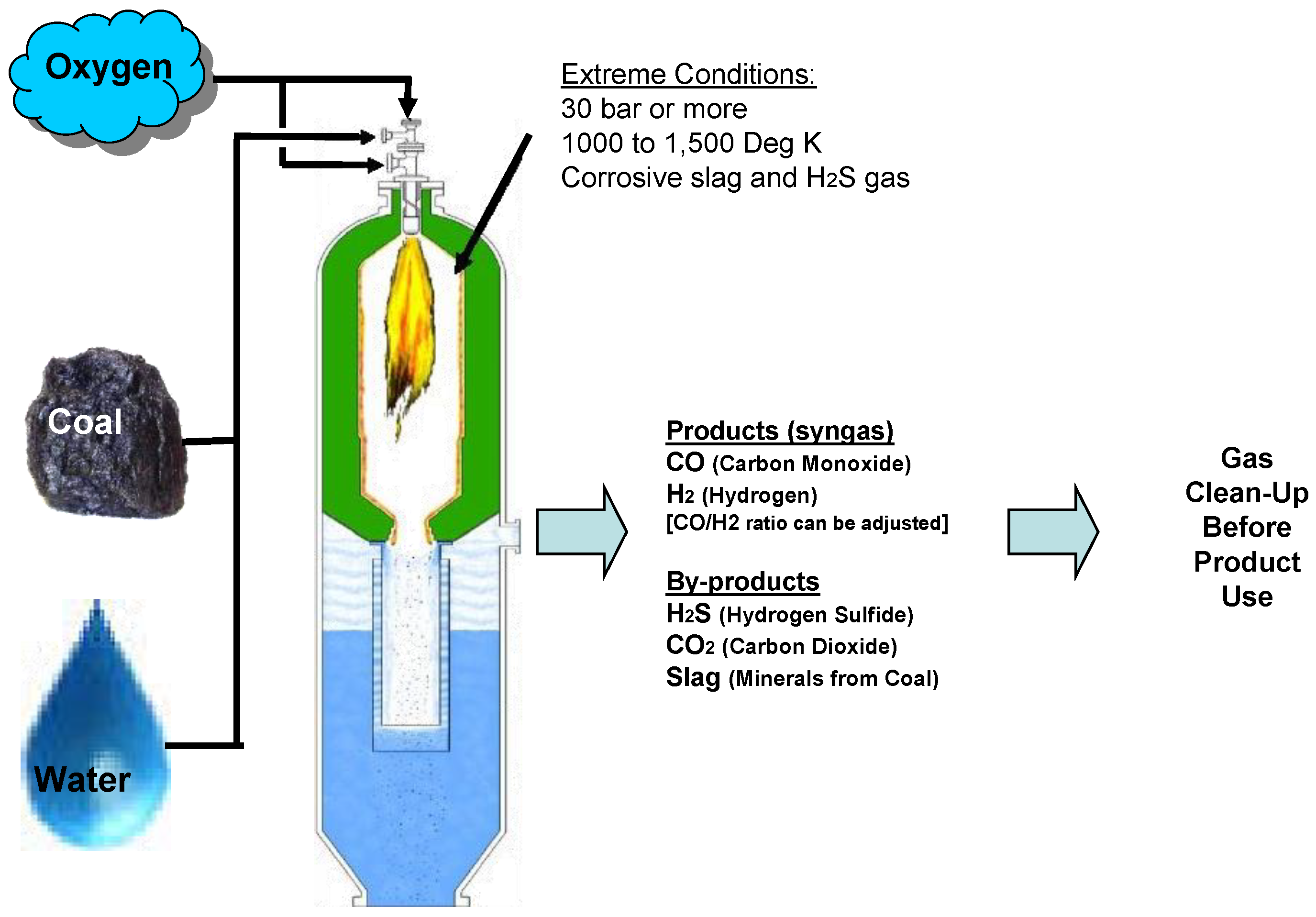
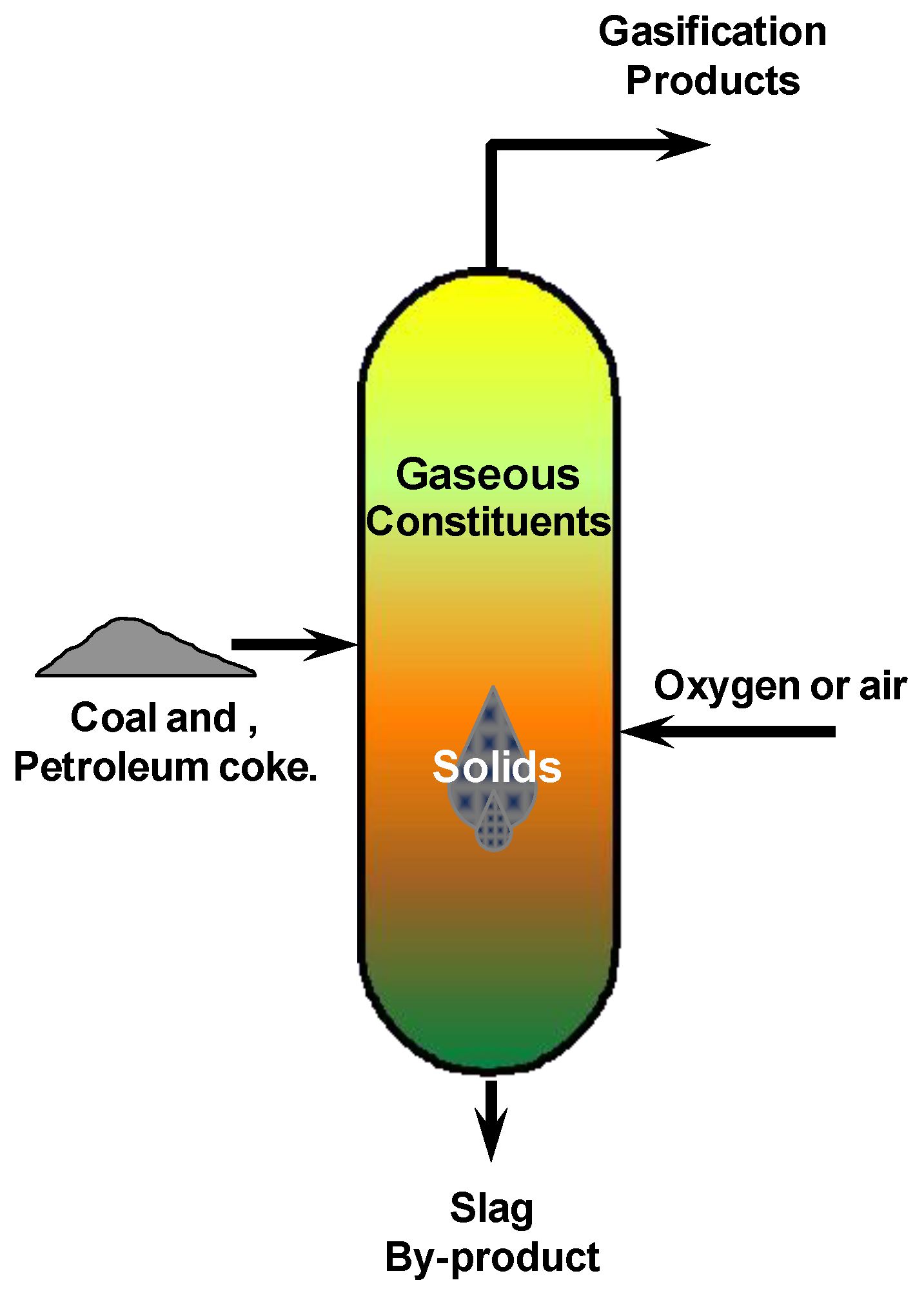
So, what is gasification? Gasification is a conversion technology converts any carbon-containing material, coal for example, into synthesis gas as shown in Figure 1. Carbon reacts with water in the form of steam and oxygen at relatively high pressure typically greater that 30 Bar and at temperatures typically reaching 1,500 K to produce raw synthesis gas or syngas, a mixture composed primarily of carbon monoxide and hydrogen and some minor byproducts. The byproducts are removed to produce a clean syngas that can be used as a fuel to generate electricity or steam, as a basic chemical building block for a large number of uses in the petrochemical and refining industries, and for the production of hydrogen. Gasification adds value to low- or negative-value feed stocks by converting them to marketable fuels and products.
Figure 1.
Gasification process basics.
There are a number of previous reviews and extended writings on gasification that can be reviewed in conjunction with this paper to get a deeper understanding of the process and various gasification technologies. These include Higmans book sited as [4], the Gasification Technologies Council website http://www.gasification.org/, the DOE Gasification website http://www.netl.doe.gov/technologies/coalpower/gasification/index.html, and numerous conferences including Gasification Technologies Annual Conference , the Clearwater Conference and the Pittsburgh Coal Conference.
1.1. History of gasification
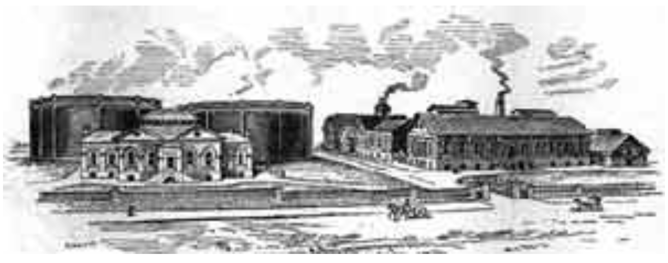
Town gas, a gaseous product manufactured from coal, containing approximately 50% hydrogen, with the rest comprised of mostly methane and carbon dioxide, with 3% to 6% carbon monoxide, is a gaseous product manufactured from coal. It supplied lighting and heating for industrializing America and Europe beginning in the early 1800s. The first public street lighting with gas took place in Pall Mall, London on January 28, 1807. Not long after that, Baltimore, Maryland began the first commercial gas lighting of residences, streets, and businesses in 1816. A typical town gas plant for the era is shown in Figure 2.
Figure 2.
Baltimore’s Bayard Street Station from “Progressive Magazine” of 1889 picturing plant prior to 1850 [2].
Figure 2.
Baltimore’s Bayard Street Station from “Progressive Magazine” of 1889 picturing plant prior to 1850 [2].

Since that time, gasification has had its ups and downs with more and longer periods of down as communities began to electrify. The few highpoints of gasification during the past hundred years are worthy of identification. Gasification was used extensively during World War II to convert coal into transportation fuels via the Fischer-Tropsch process. It has been used extensively in the last 50 to 60 years to convert coal and heavy oil into hydrogen—for the production of ammonia/urea fertilizer. The chemical industry and the refinery industry applied gasification in the 1960s and 1980s, respectively, for feedstock preparation. In the past 10 to 15 years, it has started to be used by the power industry in Integrated Gasification Combined Cycle (IGCC) plants.
2. Integrated Gasification Combined Cycle
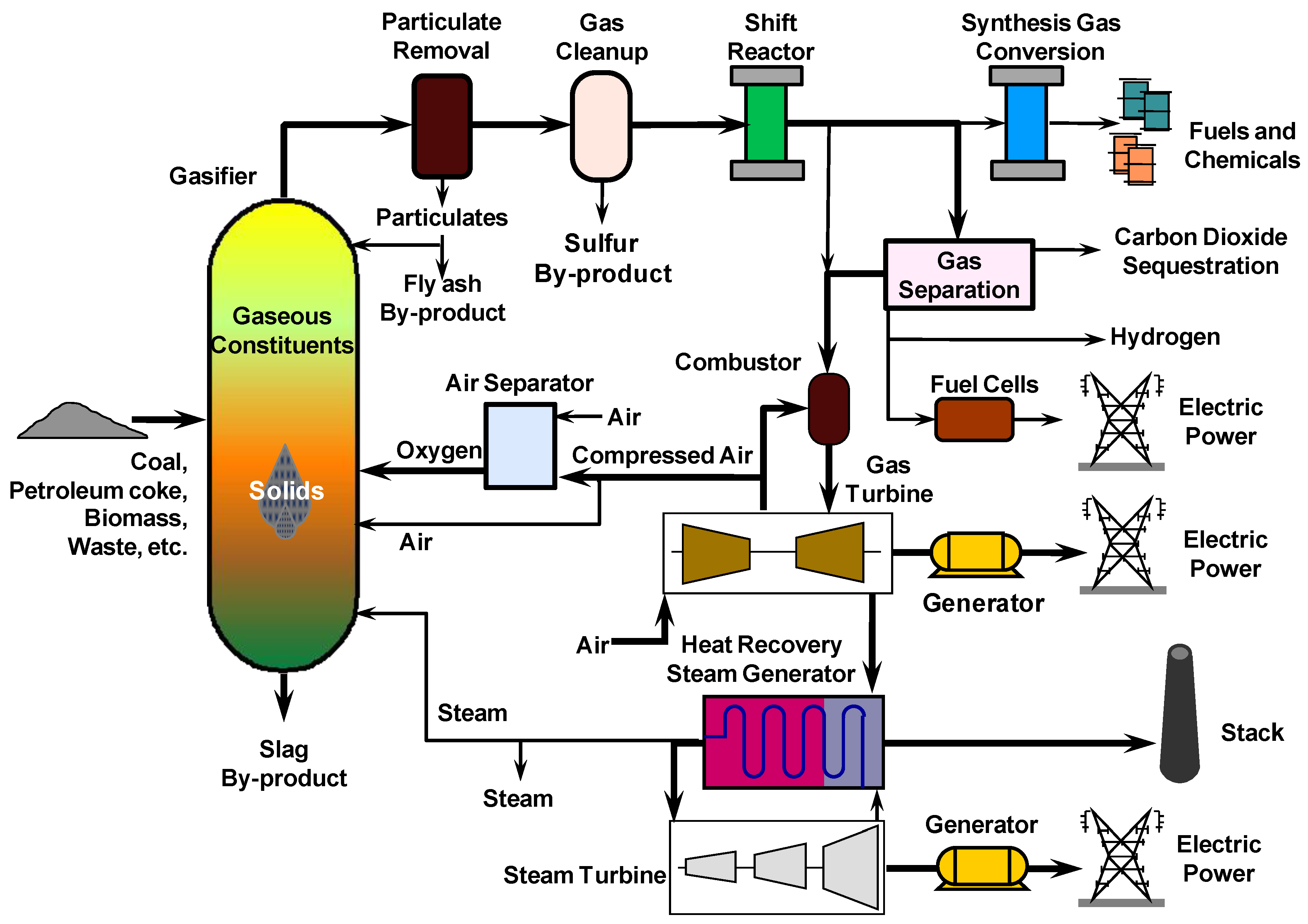
IGCC plants as shown in Figure 3 convert carbonaceous fuels/materials into electricity and could be considered first generation plants—those not requiring CO2 separation or sequestration. In this plant, the carbon containing material is fed to the gasifier along with oxygen and steam to produce the raw syngas. The raw syngas is cleaned of particulate matter and sulfur. The clean syngas is fed to the combustion turbine with the products going to a heat recovery steam generator and steam turbine.
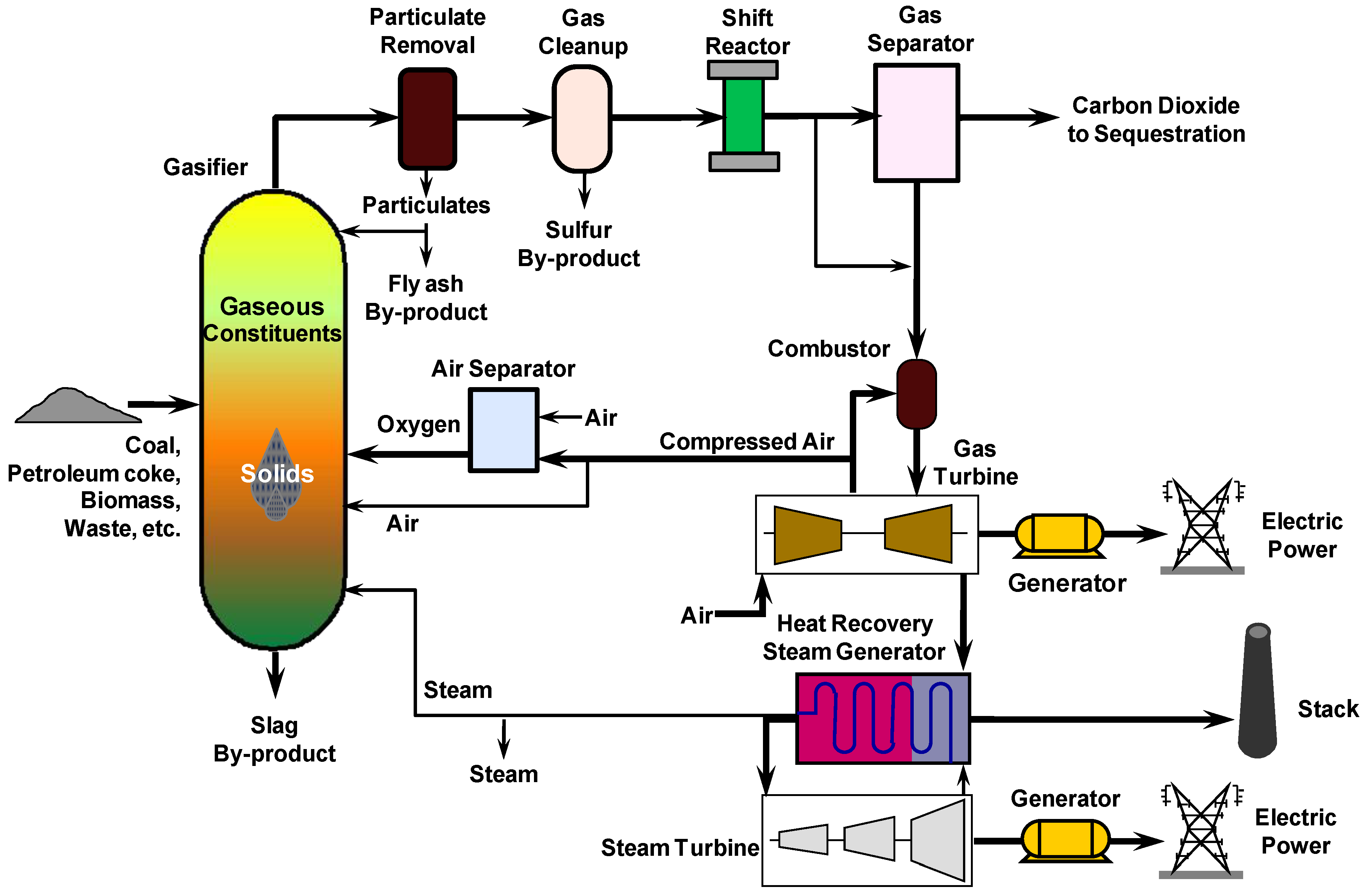
IGCC systems with carbon capture are similar to IGCC systems without carbon capture as can be seen by comparing Figure 3 and Figure 4. Figure 4 shows the IGCC system with pre-combustion capture of the carbon for sequestration. The primary difference between the two processes is that the clean syngas passes through a shift reactor and an absorption tower to remove the carbon in the form of carbon dioxide. The shift reactor converts the CO in the syngas by reacting it with water to form H2 and CO2 with the latter going to sequestration.
Figure 3.
IGCC system without carbon capture [1].
Figure 3.
IGCC system without carbon capture [1].
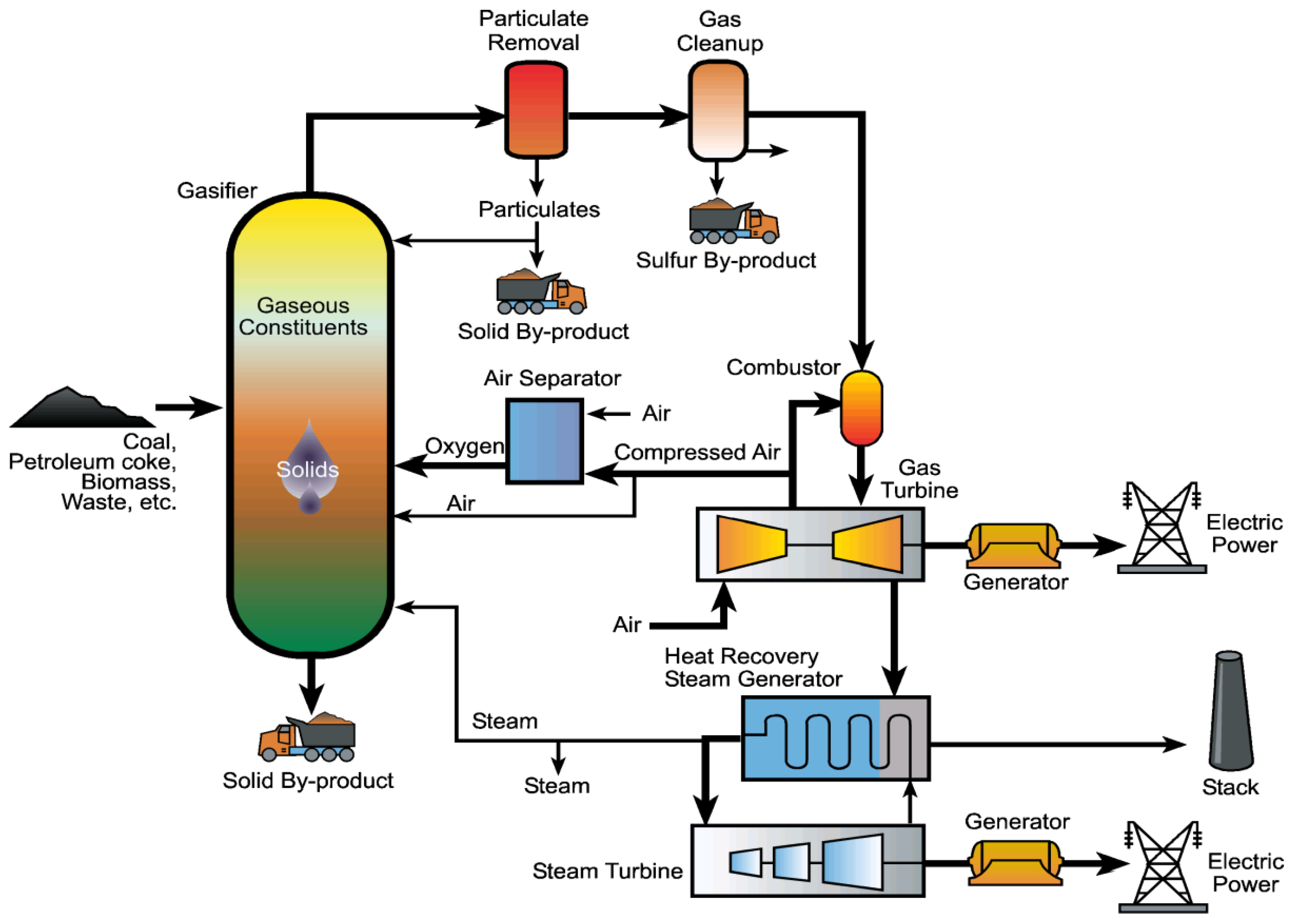
Figure 4.
IGCC with carbon capture [1].
Figure 4.
IGCC with carbon capture [1].

Figure 5 shows a conceptual poly-generation IGCC plant. In this concept, the clean syngas is shifted to change the CO/H2 ratio. A partial shift adjusts the ratio to be comparable to the end hydrocarbon product being synthesized. If power is being made as the product, the gas stream will undergo a full shift.
Figure 5.
Poly-generation plant [1].
Figure 5.
Poly-generation plant [1].

3. Gasification Versus Combustion
Gasification and combustion can essentially be considered as two ends of a continuum for reactions of coal and oxygen, although water can be added as a reactant to increase the H2 content of the products. Table 1 provides a list of the most significant reactions and the enthalpy change associated with each of these reactions. Looking at the first two reactions in the table, it is seen that coal denoted here with a C for carbon is reacted with one oxygen atom denoted here as 1/2 O2 to get carbon monoxide and with two oxygen atoms (2) to get carbon dioxide. In reality, this second reaction is not a one step process as the solid phase carbon reacts with one oxygen atom to produce carbon monoxide which then reacts with the second oxygen atom to form carbon dioxide. All of the reactions in the table are exothermic except the two reactions identified as gasification with steam and gasification with carbon dioxide. These two endothermic reactions are the reactions that are most often referred to as gasification, where the solids carbon is turned into a reactive gas through a reaction with a “non-reactive” gas (H2O or CO2). In addition to these two reactions being endothermic, they also require high temperatures to proceed.

| Reaction Process | Chemical Formula | Change in Enthalpy |
|---|---|---|
| Gasification with Oxygen | C + ½ O2 → CO | –3,922 Btu/lb C |
| Combustion with Oxygen | C + O2 → CO2 | –14,111 Btu/lb C |
| Gasification with Carbon Dioxide | C + CO2 → 2 CO | 6,267 Btu/lb C |
| Gasification with Steam | C + H2O → CO + H2 | 4,750 Btu/lb C |
| Gasification with Hydrogen | C + 2 H2 → CH4 | –2,672 Btu/lb C |
| Water Gas Shift | CO + H2O → CO2 + H2 | –650 Btu/lb CO |
| Methanation | CO + 3 H2 → CH4 + H2O | –3,181 Btu/lb CO |
Table 2 contrasts combustion and gasification. In doing so, it emphasizes the concept that combustion and gasification are two ends of a continuum in that combustion is referred to as full oxidation and gasification as partial oxidation. Also, combustion occurs in an oxidizing (excess oxygen) environment and gasification occurs in a reducing (oxygen depleted) environment. Gasification is more efficient, has lower emissions and competitive capital cost compared to combustion. With respect to the competitiveness of the cost, it is the cost of electricity that is nearly the same for both technologies, the higher capital cost of gasification is offset by the improved efficiency. Combustion is the dominate power producing technology in the world and as such is lower risk with demonstrated reliability.
Table 2.
Contrasts between Combustion & Gasification [1].
| Combustion | Gasification | |
|---|---|---|
| Chemical process | full oxidation | partial oxidation |
| Chemical environment | excess oxygen (air)-oxidizing | oxygen-starved - reducing |
| Primary product | heat (e.g., steam) | syngas (CO & H2) |
| "Downstream" products | electric power | electric power, pure H2, liquid fuels, chemicals |
| Current application | dominates coal-fired power generation worldwide | mostly chemicals and fuels, power generation demonstrated |
| Efficiency | 35–37% (HHV) | 39–42% HHV |
| Emissions | ~NSPS | ~1/10 NSPS |
| Capital cost | $1,000–1,150 /kW | competitive |
| Maturity / risk | high experience, low risk | reliability needs improved |
4. Commercial And Near Commercial Gasifier Concepts
This section briefly discusses the 12 major gasifier concepts by providing a little the history of the development of each gasifier type and giving a general description as to the type of reactor each gasifier is, such as refractory lined, slurry fired, etc. The summary on each type also gives a snapshot of the commercial environment for the technology.
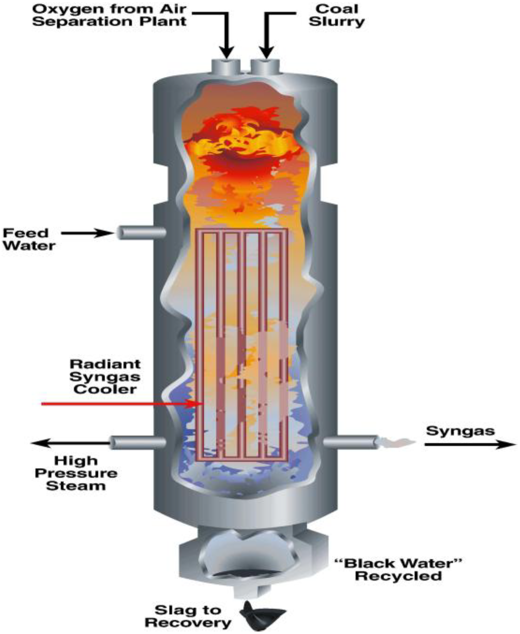
4.1. GE Energy
The GE Energy gasifier shown in Figure 6 was initially developed by Texaco which became the Chevron-Texaco gasifier upon the merger of those two companies which eventually sold the technology to GE. The technology is a coal-water slurry fed, oxygen-blown, entrained-flow, refractory-lined slagging gasifier. Two versions of the gasifier have been offered: gasifier with radiant cooler and a full quench gasifier with the latter taking precedence currently. The gasifier is good for bituminous coal, pet coke, or blends of pet coke/low-rank coals. Commercially, GE Energy provides gasification technology in an EPC alliance with Bechtel for guarantees on total IGCC plant. Presently, there are 64 plants operating, producing more than 15,000 MWth Syngas . They have 6 plants in planning
Figure 6.
GE Energy Gasifier [1].
Figure 6.
GE Energy Gasifier [1].
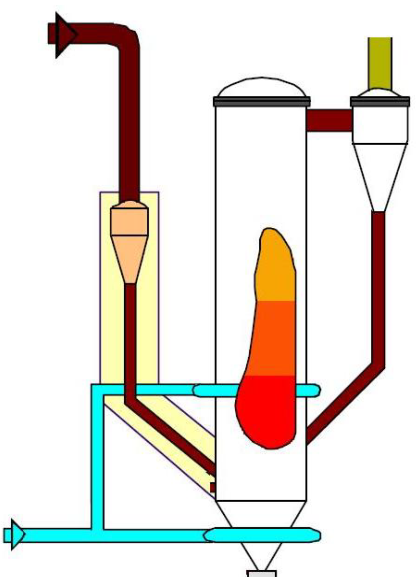
4.2. ConocoPhillips E-Gas
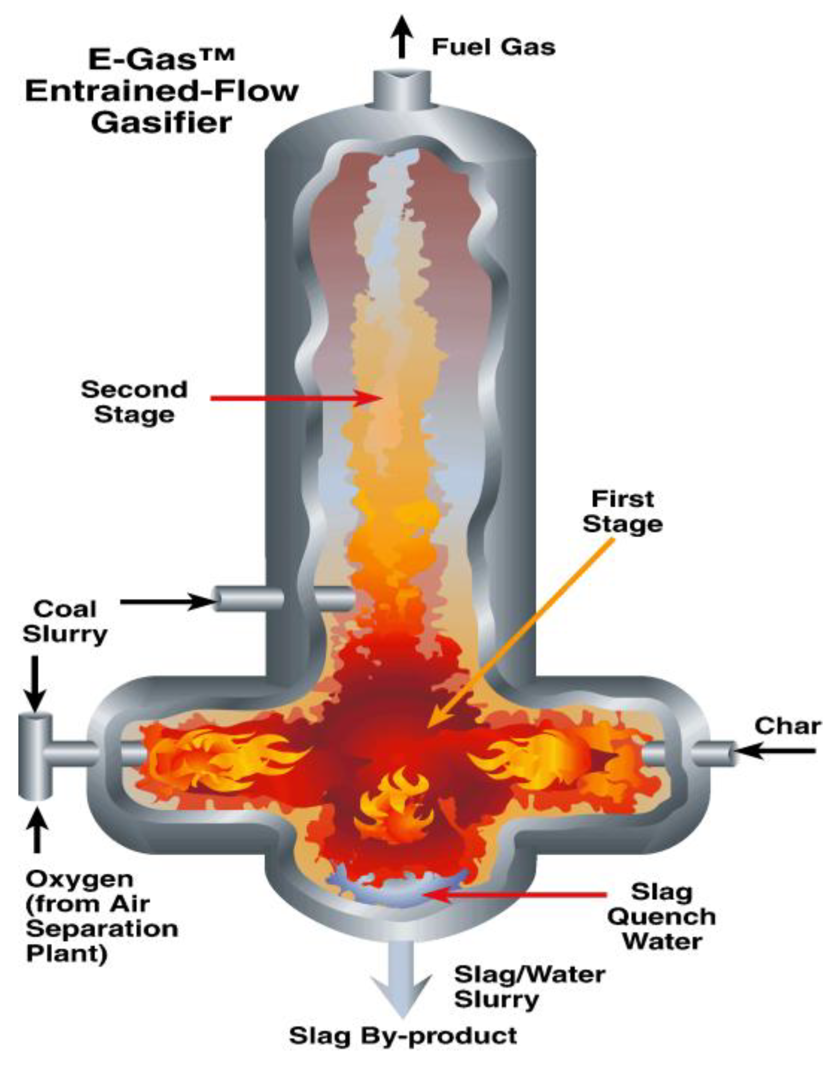
The Conoco Philips E-gas Gasifier shown in Figure 7 was originally developed by DOW Chemicals and demonstrated at the Louisiana Gasification Technology Inc. (LGTI) from 1987 through 1995. It is a two-stage gasifier with 80% of feed to first stage (lower). The gasifier is coal-water slurry fed, oxygen-blown, refractory-lined gasifier with continuous slag removal system and dry particulate removal. The E-Gas process is good for a wide range of coals, from pet coke to PRB to Bituminous and blends. Commercially, ConocoPhillips provides gasification technology and process guarantee. Project specific EPC and combined cycle supplier alliances provide balance of plant components and guarantees. There is one 590 MWth Syngas plant operating and six plants in planning.
Figure 7.
Conoco Philips E-Gas [1].
Figure 7.
Conoco Philips E-Gas [1].

4.3. Shell
The Shell gasifier has its roots dating back to 1956 leading to their first demonstration facility in1974 [3]. In the Shell gasification process, coal is crushed and dried and then fed into the Shell gasifier as a dry feed. The gasifier, as shown in Figure 8, is an oxygen-blown, water-wall gasifier eliminating refractory durability issues. It is good for wide variety of feed stocks, from pet coke to low-rank coals and has been run on biomass as well. Commercially, Shell provides the gasification technology and has alliances with both Black & Veatch and Uhde to provide the EPC. There are 26 Plants operating producing 8,500 MWth Syngas. There are 24 plants in planning.
Figure 8.
Shell Gasifier [1].
Figure 8.
Shell Gasifier [1].
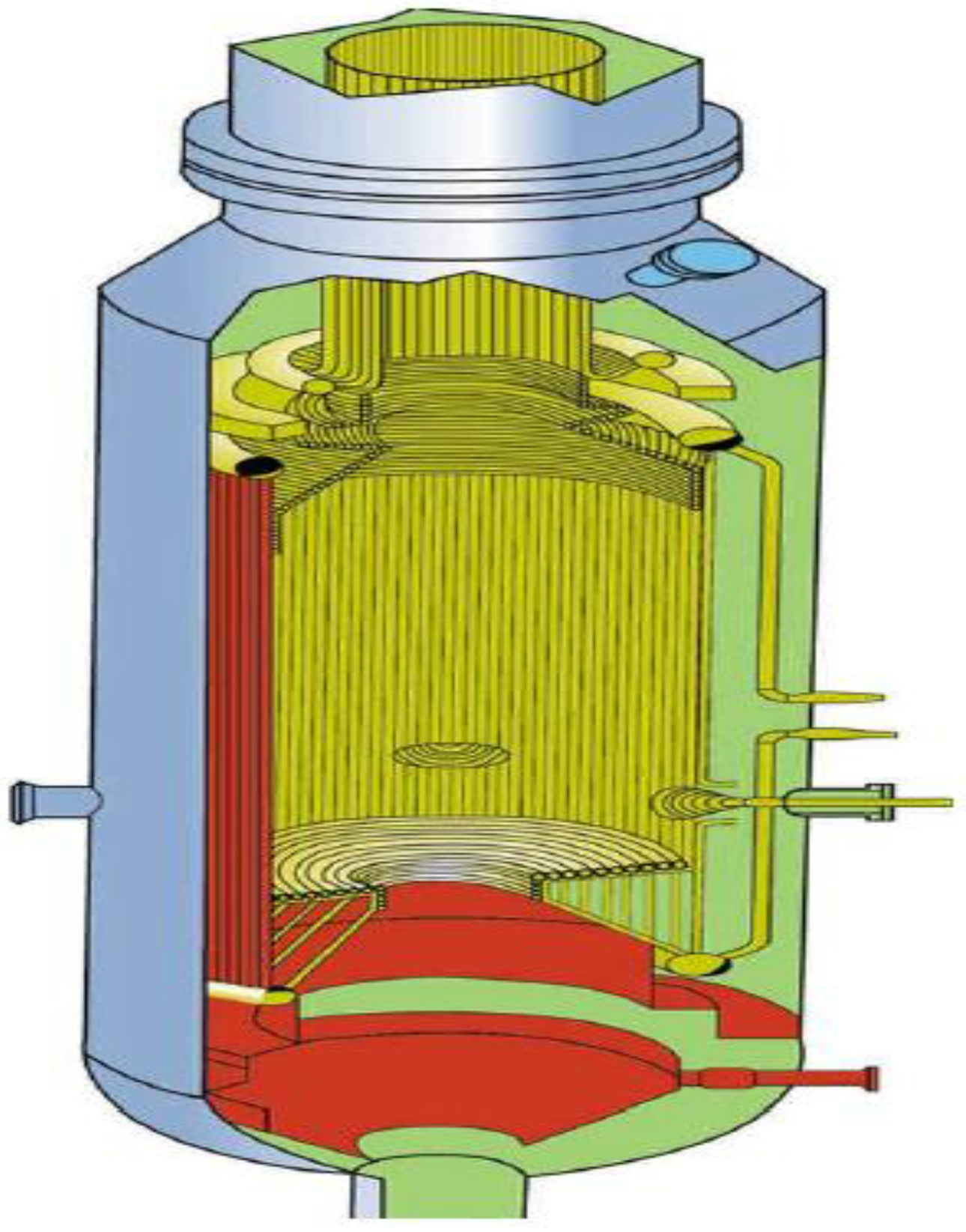
4.4. Siemens
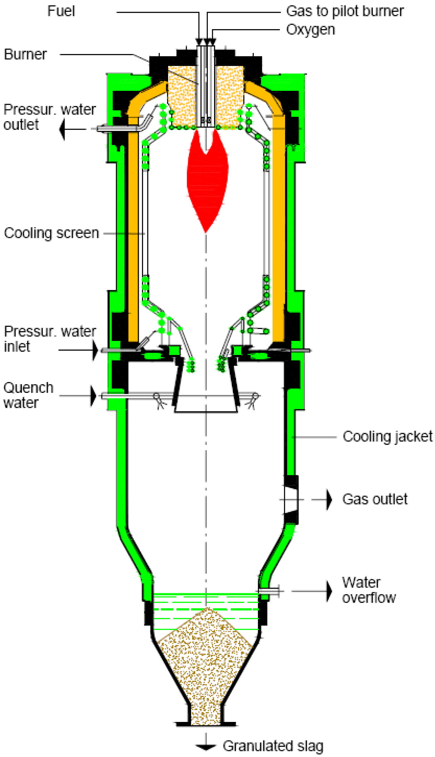
The Siemens gasifier was initially developed in 1975 for low rank coals and waste by Deutsches Brennstoffinstitut in Frieberg, Germany and was first demonstrated at Schwarze Pumpe in 1984 at a thermal rating of 200 MW [4]. The technology was marketed under the name GPS by the Noell Group and later under the name Future Energy until purchased by Siemens in 2006. The gasifier, as shown in Figure 9, is a dry feed, oxygen-blown, top fired reactor with a water wall screen in the gasifier. It is good for a wide variety of feed stocks, from bituminous to low-rank coals. Siemens provides the gasification island and power block. They recently were awarded $39 million contract for two gasifiers 500 MW each for China’s Shenhua DME Project. Presently, there is one plant operating producing 787 MWth Syngas and they have one plant in planning.
Figure 9.
Siemans Gasifier [1].
Figure 9.
Siemans Gasifier [1].

4.5. KBR Transport
The KBR transport gasifier shown in Figure 10 operates in either oxygen or air-blown configurations. It operates air blown for power generation and oxygen for liquid fuels and chemicals. It has a high reliability design based on years of designing and building FCC units for the petroleum industry. It is a non-slagging gasifier with no burners and utilizing a coarse, dry low rank coal feed. Presently, there is a 560 MWe IGCC with a 2 × 1 combined cycle to be owned by Mississippi Power Company in Kemper County, MS in design.
Figure 10.
KBR Transport Gasifier [1].
Figure 10.
KBR Transport Gasifier [1].
4.6. British Gas Lurgi (BGL)
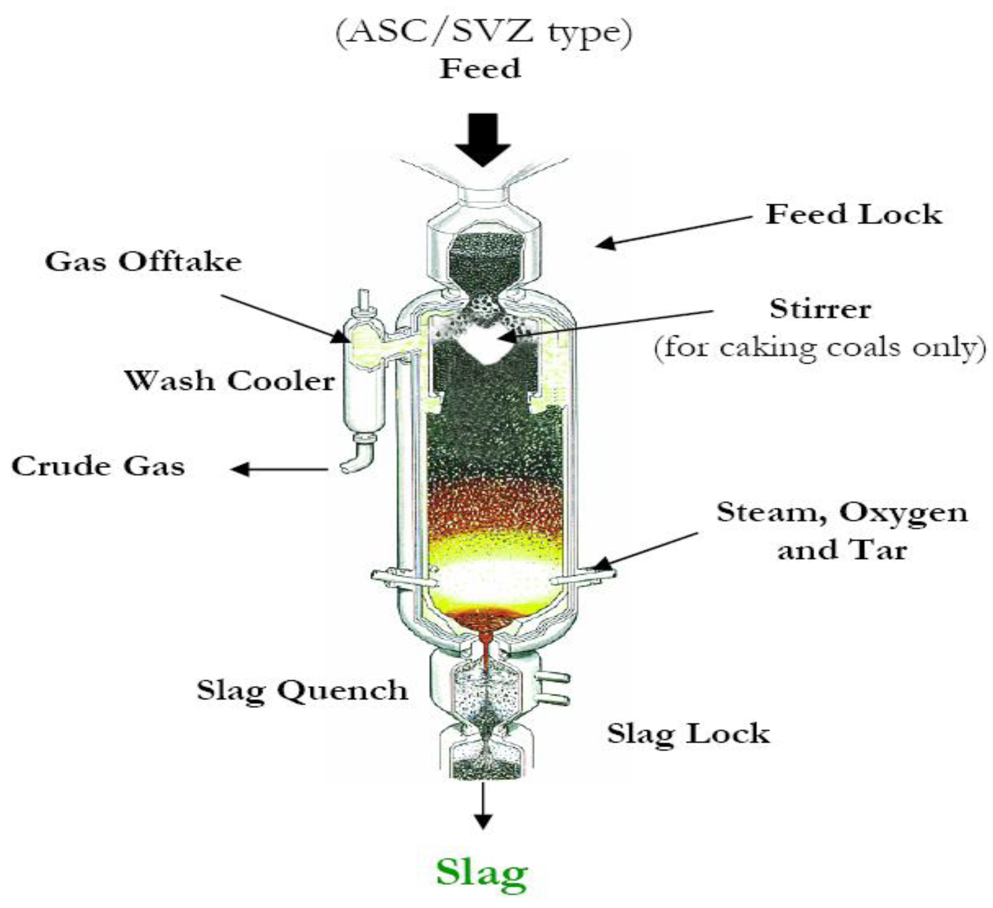
The British Gas Lurgi gasifier shown in Figure 11 is a “slagging” version of Lurgi gasifier. The BGL gasifier was developed by British Gas during the period from 1958 to 1965 at the Gas Council Midlands Research Station where it operated 13 ft gasifier, 100 t/day [5]. It is a dry feed, oxygen-blown, refractory-lined gasifier. It is good for wide range of coals including opportunity fuel blends with RDF, tires, and wood waste. It is a modular design by Allied Syngas which will build, own and operate in North American. A 500 TPD demonstration plant operated from 1986 to 1990. And the first commercial plant at Schwarze Pumpe operated 2000–2005.
Figure 11.
British Gas Lurgi Gasifier [1].
Figure 11.
British Gas Lurgi Gasifier [1].

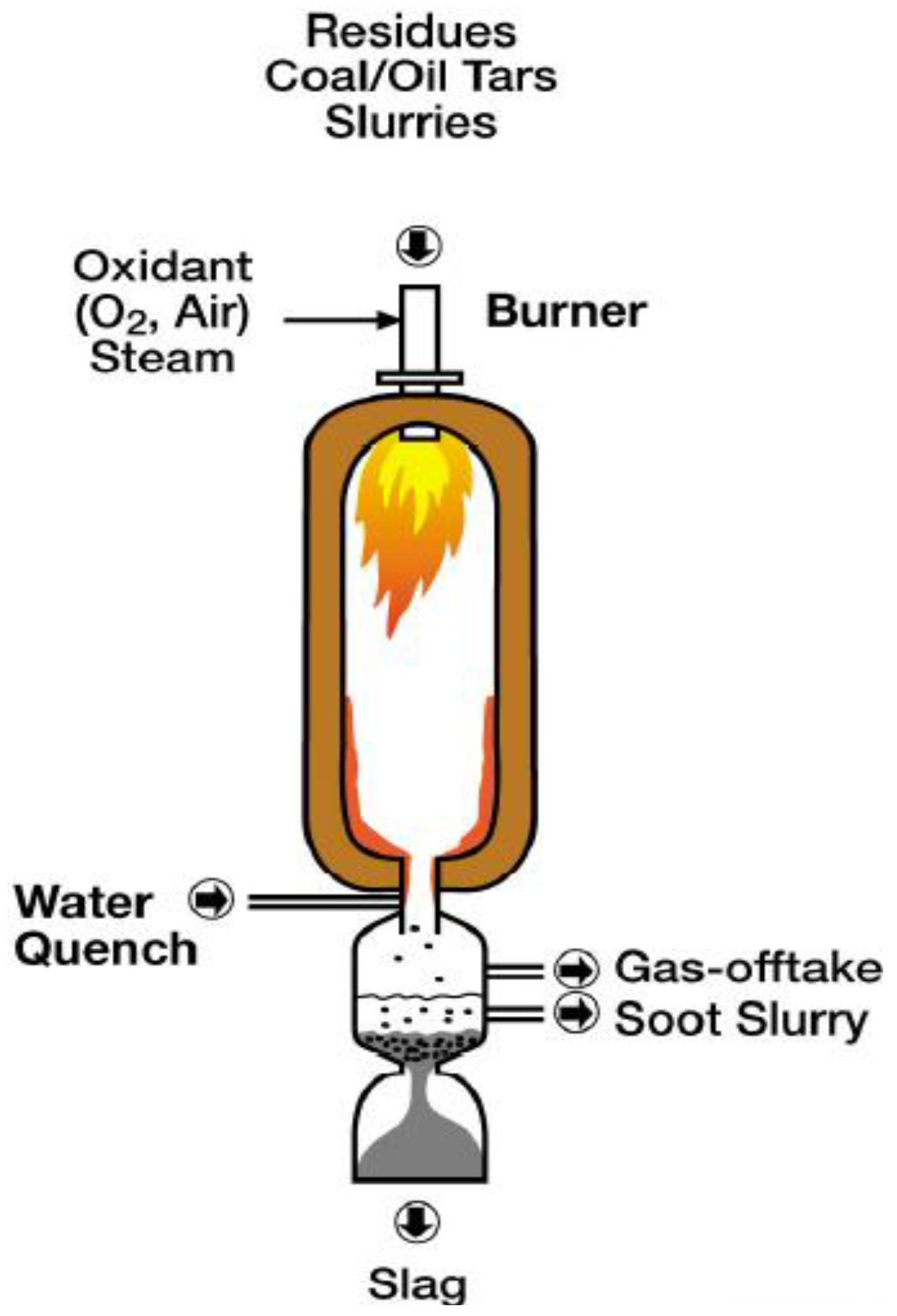
4.7. Multi Purpose (MPG) Gasifier
Lurgi developed the MPG technology shown in Figure 12 based on it’s fixed-bed gasification process. It is an oxygen-blown, down fired, refractory lined gasifier good for wide range of feed stocks including petroleum coke (petcoke) and coal slurries as well as waste. It operates in a quench configuration for coal/petcoke feed stocks. Lurgi demonstrated a “Reference plant” at Schwarze Pumpe which has been in operation since 1968.
Figure 12.
Lurgi Multi Purpose Gasifier [1].
Figure 12.
Lurgi Multi Purpose Gasifier [1].

4.8. Lurgi Mark IV Gasifier
The Lurgi Mark IV gasifier is an extension of the original proven moving bed Lurgi gasifier. As shown in Figure 13, it has a dry feed system with lock hoppers to provide the pressure seal. It is an oxygen blown, dry bottom gasifier. There is extensive experience worldwide with low rank coals. There are eight plants operating worldwide including one in North Dakota producing 18,600 MWth Syngas in 14 gasifiers. The plant has two trains of 7 gasifiers each. It was originally designed to have one unit as a spare in each train. Operating all 7 gasifiers has improved the plant’s economic performance.
Figure 13.
Lurgi Mark IV Gasifier [1].
Figure 13.
Lurgi Mark IV Gasifier [1].
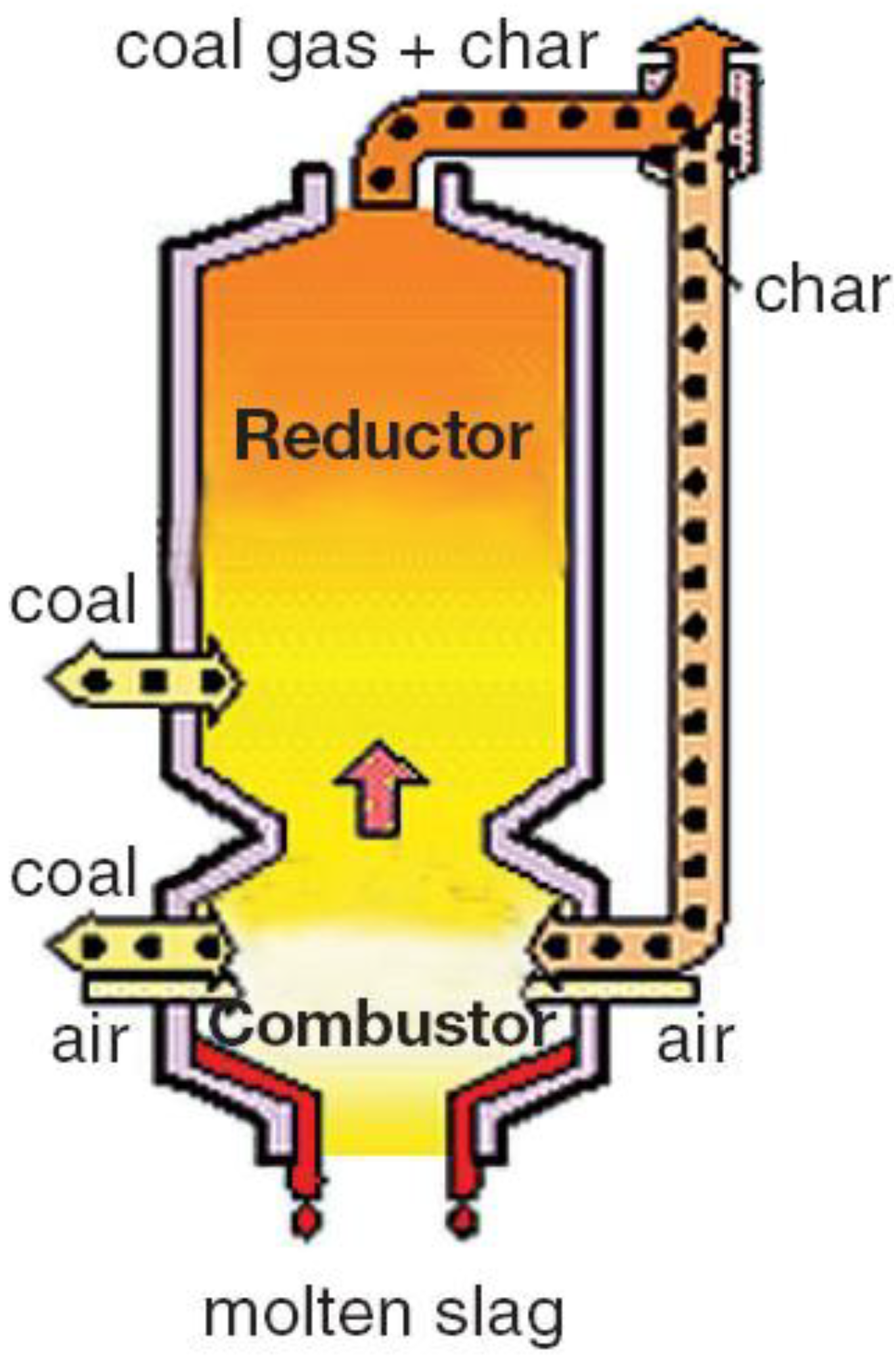
4.9. MHI Gasifier
The Mitsubishi Heavy Industries (MHI) gasifier is based upon the Combustion Engineering air-blown slagging gasifier and co-developed between Combustion Engineering (and its subsequent owners) and MHI. As shown in Figure 14, it has a dry feed system, suitable for low rank coals having high moisture contents. It is an air blown two-stage entrained bed slagging gasifier utilizing membrane water-wall construction. There is one demonstration plant in operation producing 250 MWe and located in Nakoso, Japan. It underwent startup September of 2007.
Figure 14.
MHI Gasifer [1].
Figure 14.
MHI Gasifer [1].

4.10. U-Gas
The U-Gas process is a fluidized bed gasifier incorporating a dry feed system as shown in Figure 15. It can operate on all coals and coal / biomass blends. It is highly efficient in either the air or oxygen blown configuration producing a non-slagging/bottom ash. There is presently a 30 year license agreement with Synthesis Energy Systems (SES) in place. There is twenty plus years of experience including plants in Shanghai, Finland and Hawaii. Two plants are presently in operation producing 520 MWth Syngas.
Figure 15.
U-Gas Process [1].
Figure 15.
U-Gas Process [1].
4.11. High Temperature Winkler Gasifier
The High Temperature Winkler Gasifier, shown in Figure 16, is a fluidized bed gasifier utilizing a dry feed and operating either in the oxygen or air-blown modes. It produces a dry bottom ash. It was developed to utilize lignite coal but is capable of efficiently gasifying a broad range of feed stocks. The R&D is complete and has been marketed for waste materials as the Uhde PreCon process. A demonstration plant shut down in 1997. It under went 20 years of testing for 67,000 operating hours gasifying 1.6 million metric tons dry lignite to produce 800,000 metric tons methanol.
Figure 16.
High Temperature Winkler Gasifier [1].
Figure 16.
High Temperature Winkler Gasifier [1].

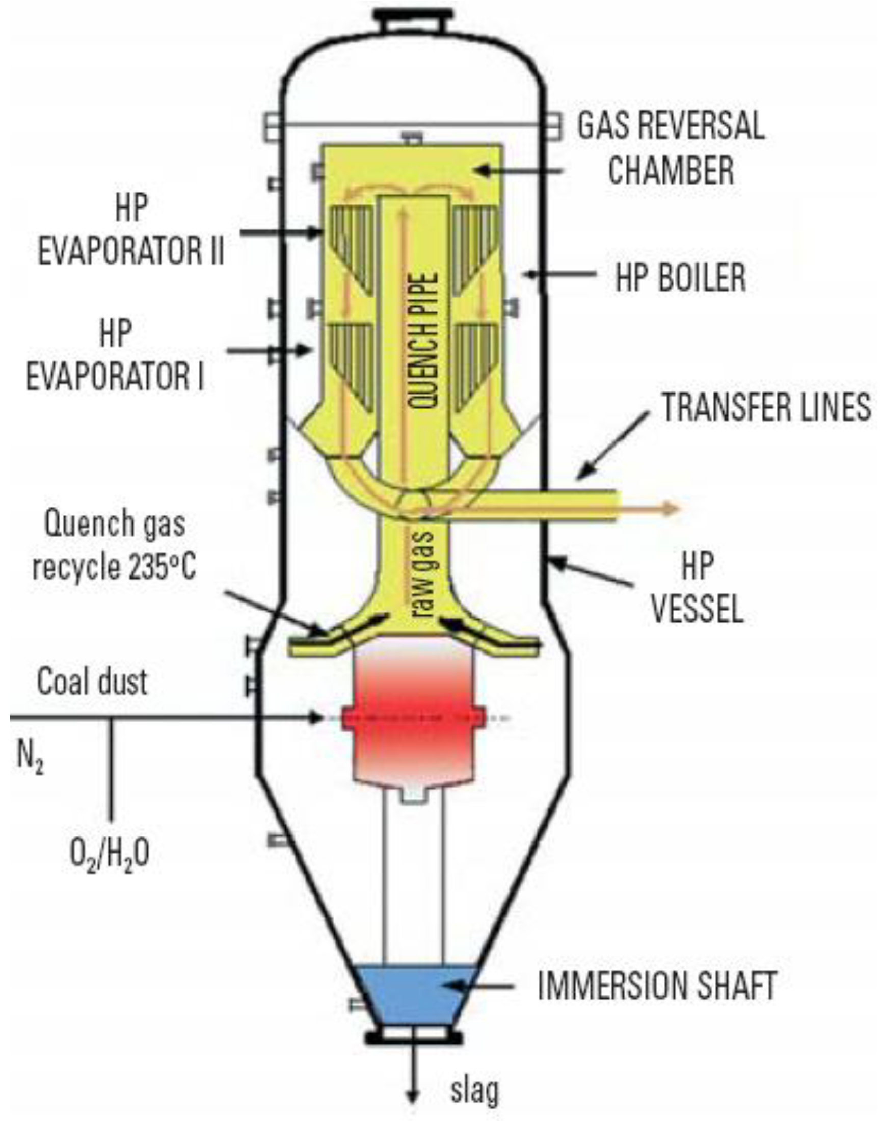
4.12. PRENFLO™ Gasifier/Boiler (PSG)
The PRENFLO™ Gasifier/Boiler is a pressurized entrained flow gasifier with steam generation being marketed by Uhde. As shown in Figure 17, it is an oxygen blown, dry feed, membrane wall gasifier that is able to gasify a wide variety of solid fuels including hard coal, lignite, anthracite, refinery residues, etc. A demonstration plant in Fürstenhausen, Germany gasified 48 TPD. The technology is used in world’s largest solid-feedstock-based IGCC plant in Puertollano, Spain.
Figure 17.
PRENFLO™ [1].
Figure 17.
PRENFLO™ [1].

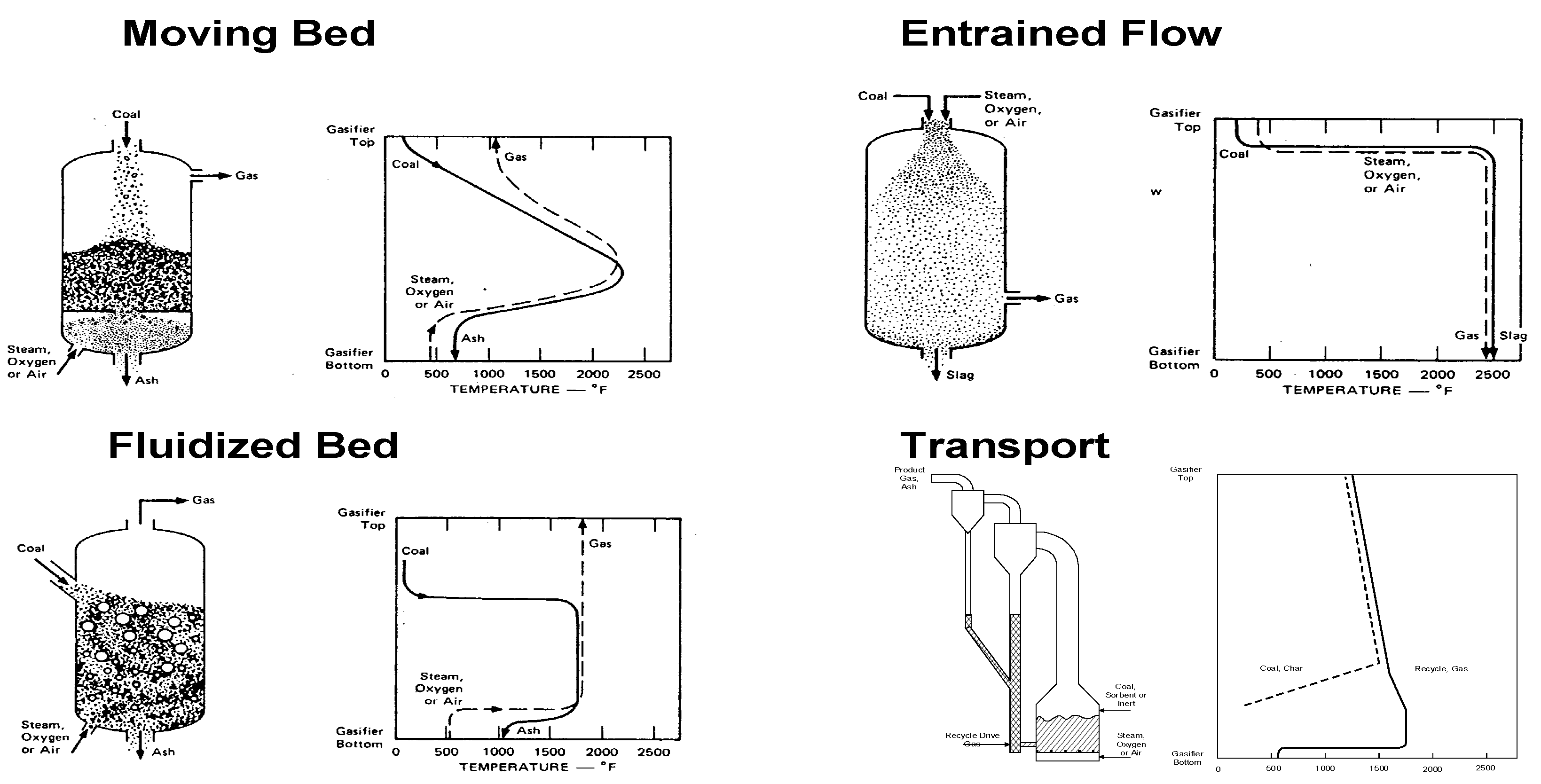
5. Gasifier Configurations
All of the gasifiers discussed above fall into basically four primary gasifier configurations: moving bed, fluidized bed, entrained flow and transport as shown in Figure 18. Each of these is defined on how the reactor brings about contact with the coal and the reactive gas. Figure 18 presents a cartoon of each of the gasifier types and presents a graph of the gas and solids (coal particle) temperature as they traverse the height of the gasifiers. A summary of the gasifier types is presented in Table 3. The moving/fixed bed gasifier category refers to the Lurgi Mark IV (dry bottom) and the British Gas Lurgi (slagging) with both having dry feed systems. There are three entrained flow gasifiers produced by Conoco-Philips, General Electric and Shell. The Shell unit is a dry feed gasifier where as the Conoco-Philips and the General Electric are slurry fed gasifiers. The fluidized bed and the transport gasifiers dry fed non-slagging gasifiers.
Figure 18.
Gasifier Configurations [1].
Figure 18.
Gasifier Configurations [1].

| Moving Bed | Fluidized Bed | Entrained Flow | Transport Flow | |||
|---|---|---|---|---|---|---|
| Ash Condition | Dry | Slagging | Dry | Agglomerate | Slagging | Dry |
| Coal Feed | ~ 2 in | ~ 2 in | ~ ¼ in | ~ ¼ in | 100 Mesh | ~ 1/16 in |
| Fines | Limited | Better than dry ash | Good | Better | Unlimited | Better |
| Coal Rank | Low | High | Low | Any | Any for dry feed | Any |
| Gas Temp.(F) | ||||||
| Oxidant Req. | Low | Low | Moderate | Moderate | High | Moderate |
| Steam Req. | High | Low | Moderate | Moderate | Low | Moderate |
| Issues | Fines and hydrocarbon liquids | Carbon Conversion | Raw Gas Cooling | Control Carbon inventory ad carryover | ||
5.1. Fixed/Moving Bed Gasifiers Performance
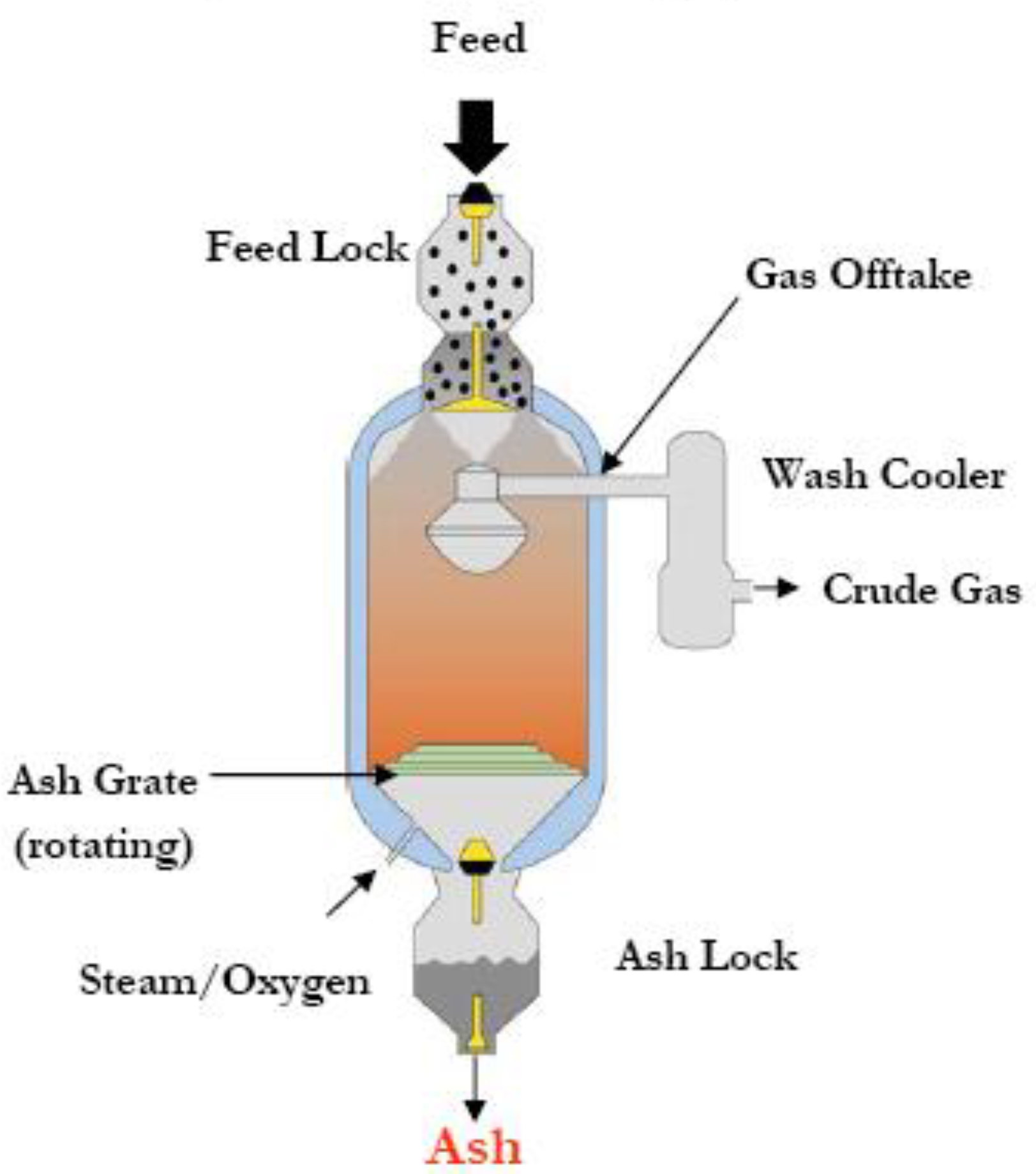
A sketch of the Fixed/Moving Bed Gasifiers is shown in Figure 19. Lurgi produces the non-slagging unit of this type while British Gas designed the slagging version of this technology, often referred to as the British Gas Lurgi (BGL). These units are both counter current flow of gas and solids.
The product gas contains hydrocarbons, tar and water. These exist in the product due to the counter current flow and the inherent recuperation of the sensible energy in the gas through devolatilization and coal drying giving these gasifiers the highest cold gas efficiency of any of the gasifiers.
Figure 19.
Typical Configuration for Dry and Slagging Moving Bed.

Hydrodynamically, the reactors resemble flow through a porous media as shown in Figure 20. Although in this gasifier, both the continuous phase (gas) and the solids phase flow. These two components flow in a counter current fashion. That is the solids move down while gas moves up. These types of reactors can be problematic due to non-uniform flow which may be a result of particles agglomerating and over packing with fines. All of these issues lead to poor inter-phase mixing, unreacted carbon, hot spots and lower conversion.
Figure 20.
Moving Bed Gas Solids Flow Patterns.
Kinetically, the moving bed is a low temperature reactor operating in the kinetic controlled shrinking core reaction mode pictured in the carton shown in Figure 21. The burnout time or conversion time for a particle fed to the top of the gasifier is
where: τ is the time for complete conversion, ρB is the coal particle density, 2 is 1/stoichiometric coefficient for O2, R is the particle radius, k is the combined kinetic and mass transfer rate constant, and C is the concentration of O2 [6].
Figure 21.
Particle Time History in Moving Bed.
Typical product compositions are provided in Table 4 for oxygen blown operation for both the dry ash Lurgi configuration and the slagging BGL configuration. Table 5 presents typical product gas compositions for air blown operation of the Lurgi dry bottom configuration.
| Oxygen Blown | |||||
|---|---|---|---|---|---|
| Dry Bottom Moving Bed | Slagging Moving Bed | ||||
| Coal type | Brown/Lignite | Sub-Bit | Bit | Anth | Bit |
| Pressure atm | up to 92 | 25 | 24–100 | ~ | 21.0–32.0 |
| Gas Composition (Dry) | |||||
| CO | 17.4–19.7 | 15.1 | 15.2–19.5 | 22.1 | 55.0–61.2 |
| CO2 | 30.4–32.2 | 30.4 | 28.9–32.4 | 30.8 | 2.4–3.5 |
| H2 | 37.2–37.2 | 41.1 | 38.3–42.3 | 40.7 | 28.1–31.5 |
| N2 | 0.5–0.5 | 1.2 | 0.5–1.6 | 0.4 | 3.3–3.3 |
| CH4 | 11.8–12.1 | 11.7 | 8.6–10.1 | 5.6 | 5.0–8.3 |
| H2S | 0.1 | 0.5 | 0.8–1.1 | ~ | 1.3–1.3 |
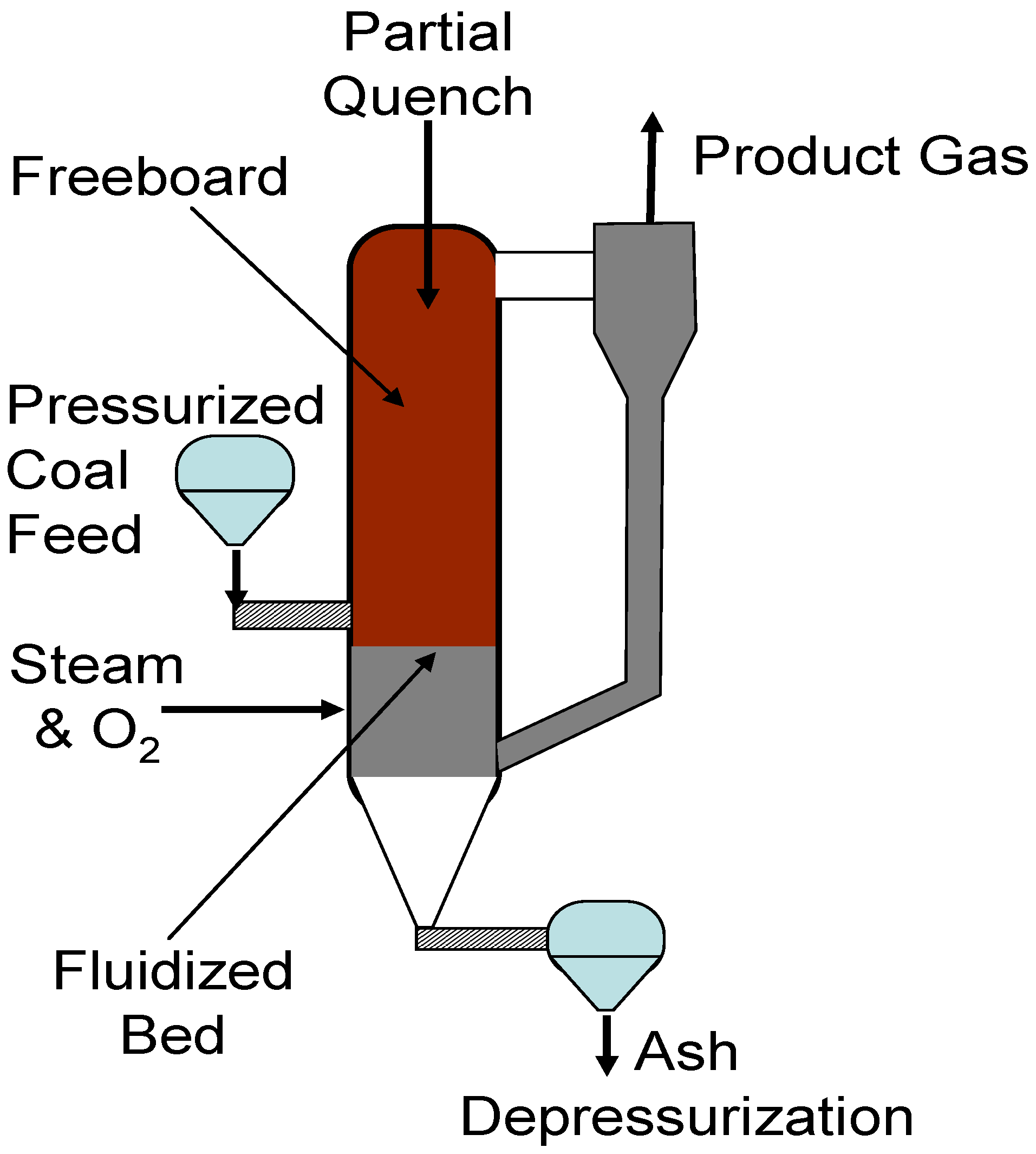
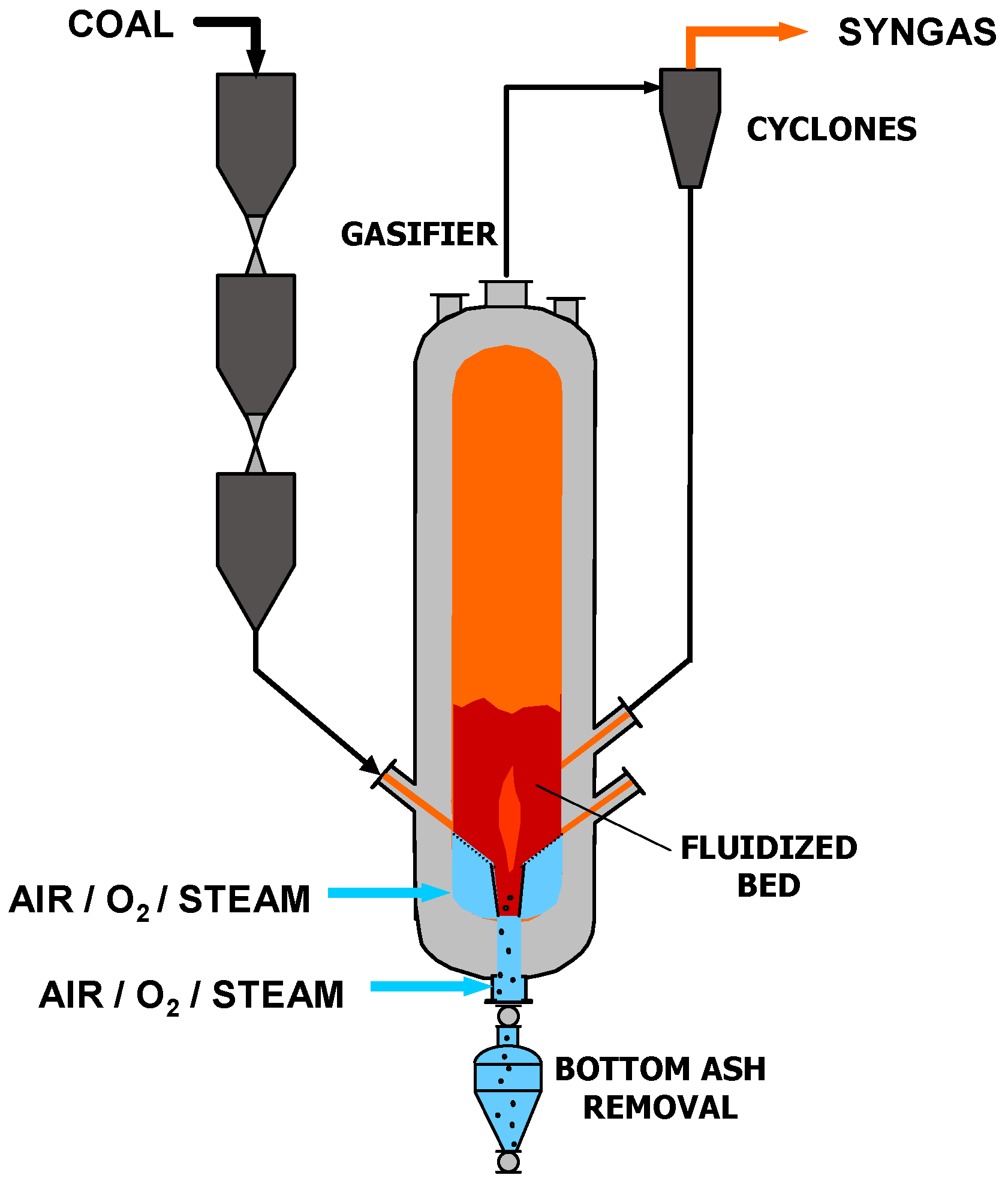
5.2. Fluidized Bed Gasifier Performance
The Gas Technology Institute’s (GTI’s) U-Gas process and Winkler gasifier are examples of fluidized bed gasifiers. Figure 22 presents a typical configuration of a fluidized bed gasifier. Operating in the fluidized bed mode, these reactors are very well mixed. All processes take place simultaneously throughout bed. Lime, limestone or dolomite can be added for in-bed sulfur removal. Capturing sulfur limits the maximum temperature in these gasifiers to about 1,832 F or less which, also keeps the ash from slagging. Gasification kinetics determines bed volume and the fluidization velocity determines cross sectional area such that the bed height is fixed. Tar is cracked in Freeboard.
Figure 22.
Fluidized Bed Gasifier Concept.

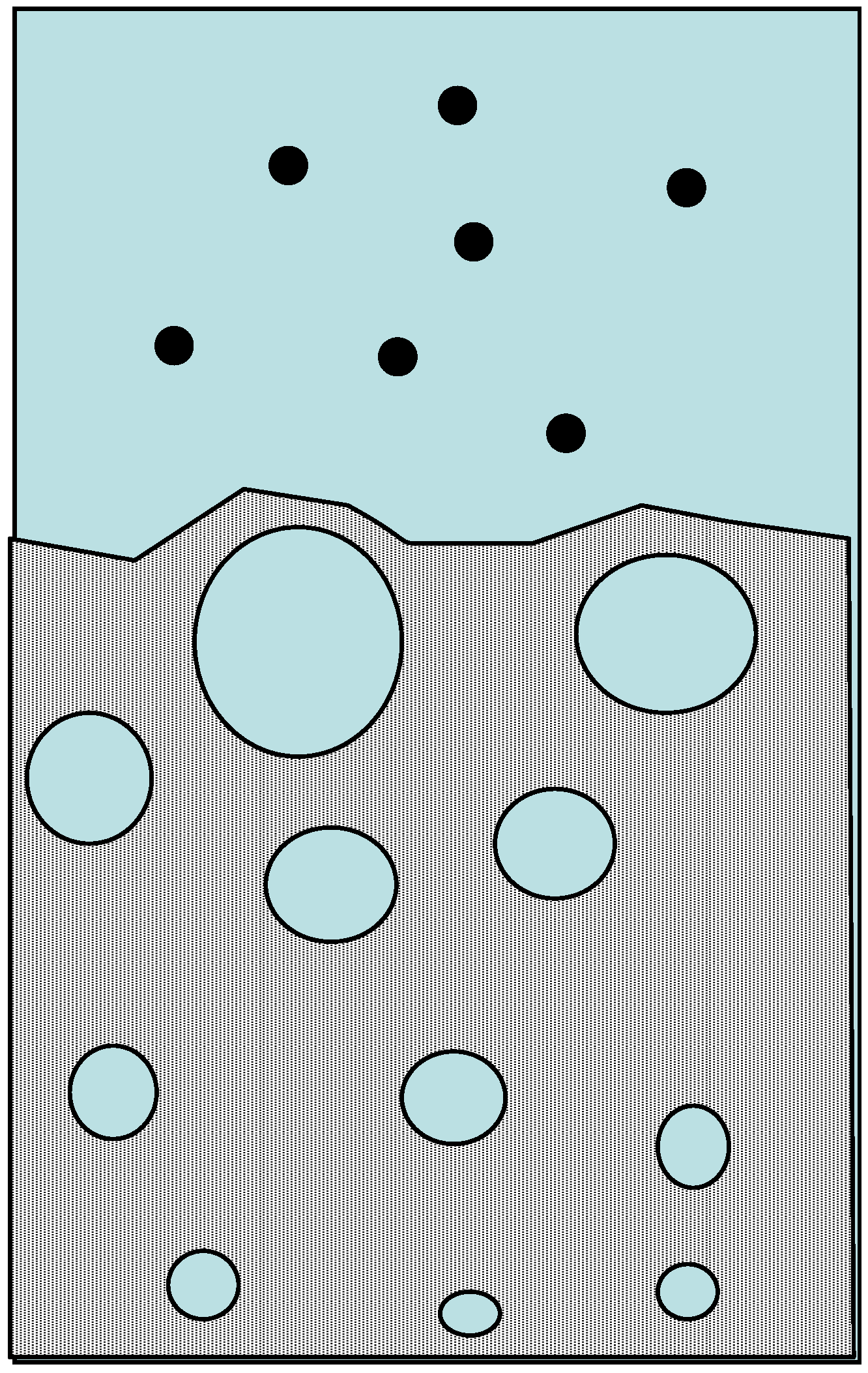
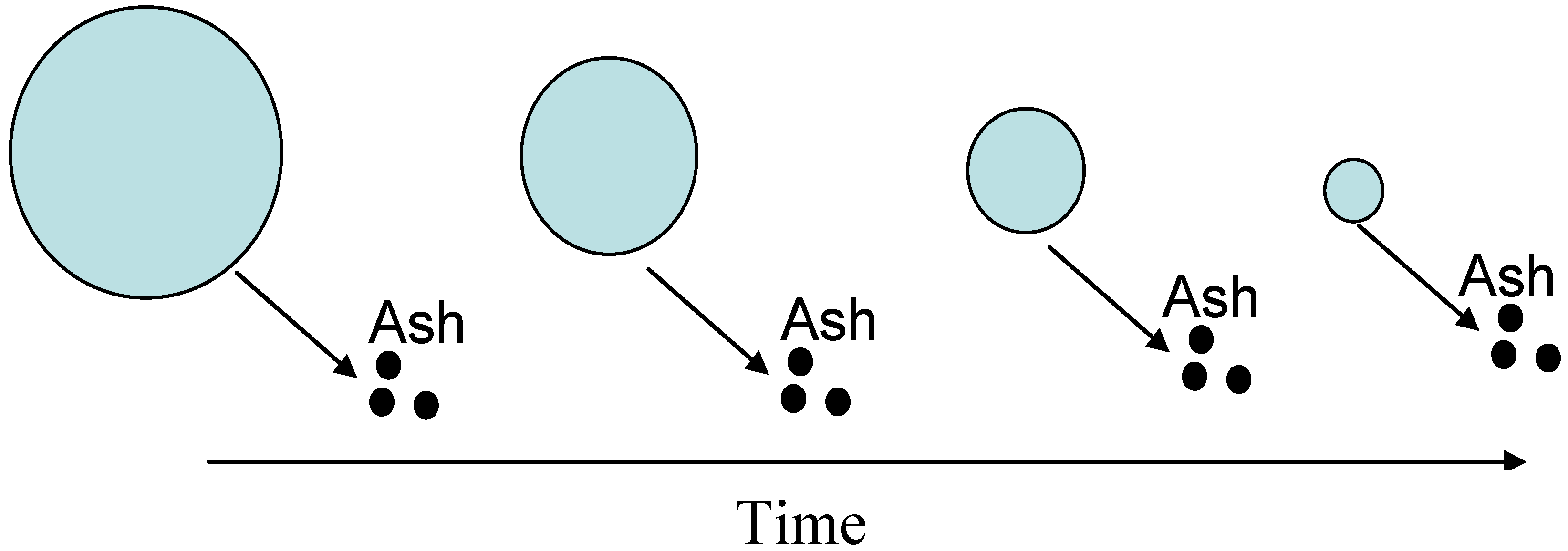
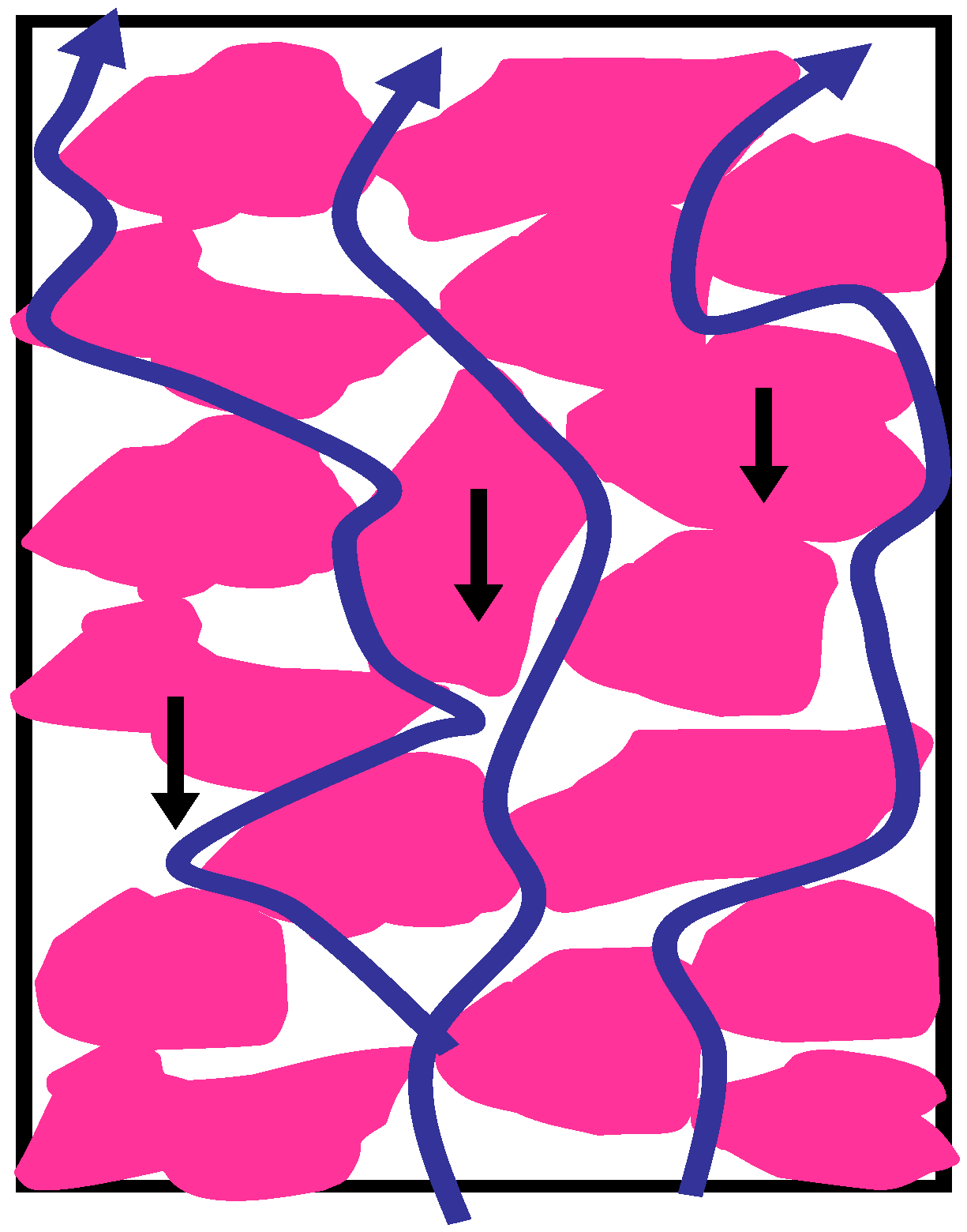
Hydrodynamically, fluidized beds are more complicated than fixed bed reactors where bubbles of excess gas induced and promote mixing as shown in Figure 23. The better mixing of gas and solids leads to better inter-phase transport and better conversion of the coal. In addition, the mechanical movement of the solids against each other essentially scrubs the ash from particles.
Figure 23.
Bubbling Fluidized Bed Hydrodynamics.

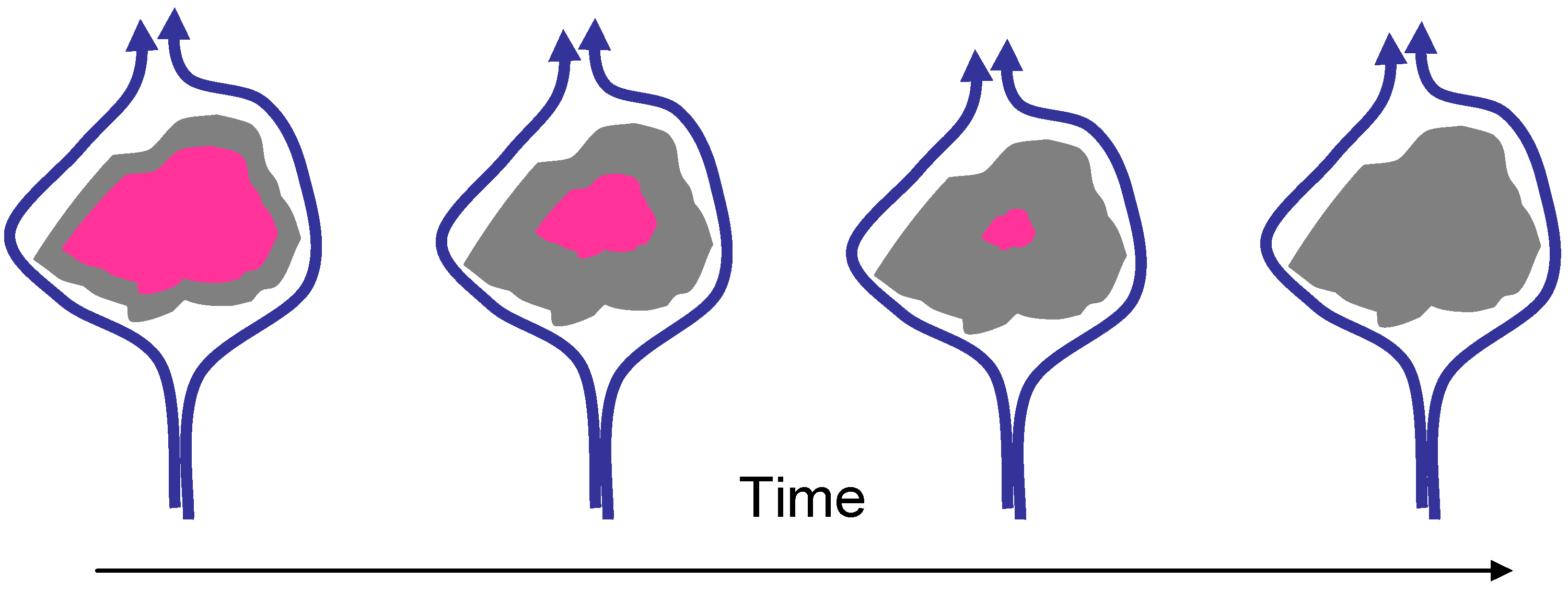
Kinetically, because of the scrubbing of the reacted layer, the burnout or conversion follows a shrinking particle as pictured in Figure 24. The conversion time can be calculated from the equation
where: τ is the time for complete conversion, ρB is the Coal particle density, 2 is 1/stoichiometric coefficient for O2, R is the particle radius, k is the combined kinetic and mass transfer rate constant, and C is the concentration of O2 [6].
Figure 24.
Particle Time History in Fluidized Bed.
These units have moderate cold gas efficiencies and they accept a broad range of coals. Typical gas compositions are presented in Table 6 for oxygen blown gasification in a fluidized bed when using lignite and bituminous coal. Table 7 presents air blown gas composition data for the same coal types.
5.3. Entrained Flow Gasifier Performance
There are seven entrained flow gasifiers in the market place at this time and discussed above. These are the Conoco-Phillips E-Gas, GE (formerly Texaco), Shell, PrenfloTM , MHI, Siemens and MPG gasifiers. A sketch of the units can be seen in in the cartoon presented in Figure 25. In these gasifiers, widely dispersed small particles are radiantly heated to high temperature for slagging and rapid gasification. Some of the issues: obtaining uniform feed, slurry drying, and separation of gas production from the heat recovery. The volume is determined from conversion time for average particle. These units have a relatively low cold gas efficiency and high O2 demand.
Figure 25.
Typical Entrained Flow Gasifier [1].
Figure 25.
Typical Entrained Flow Gasifier [1].

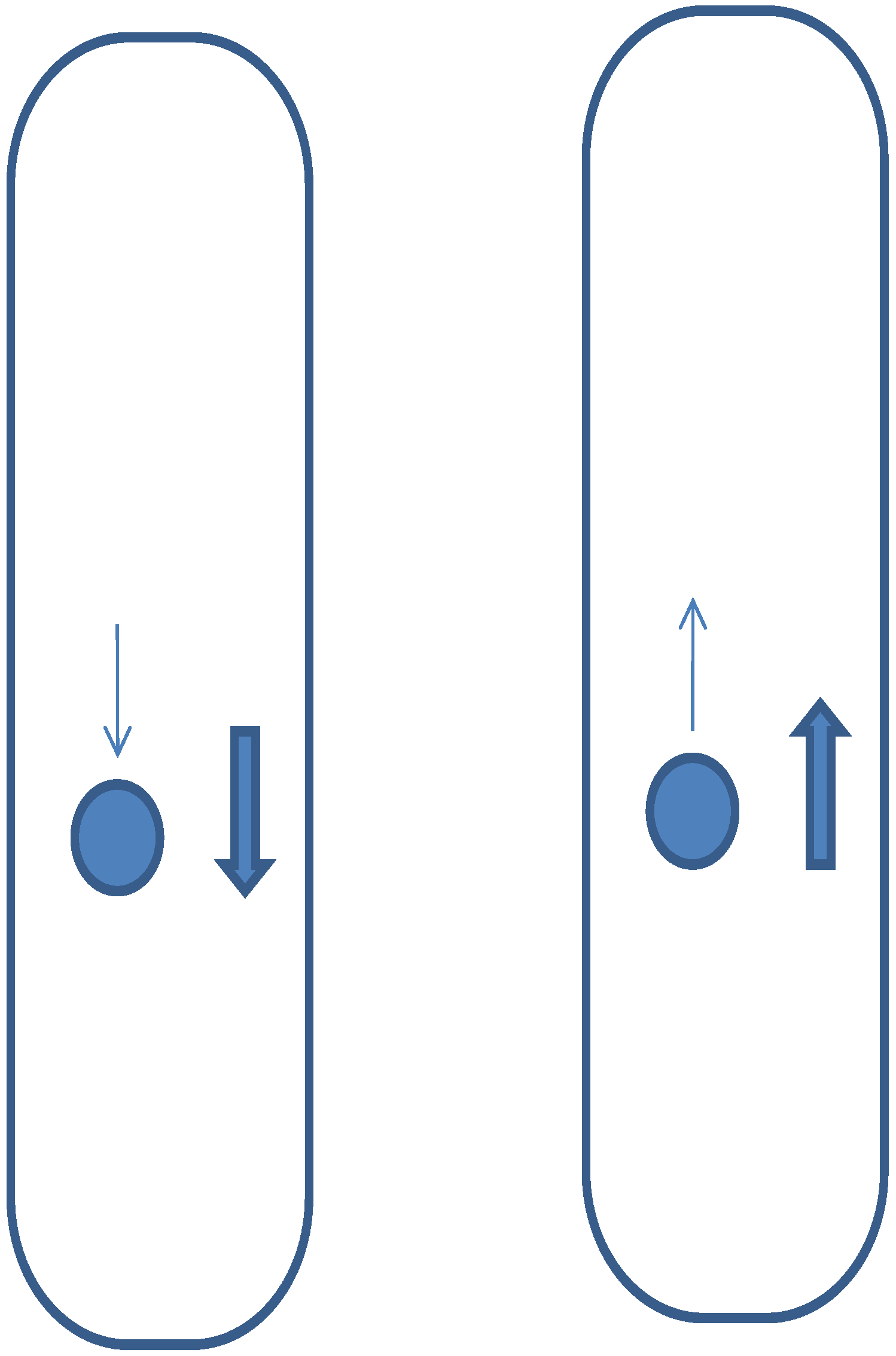
Hydrodynamically, entrained flow gasifiers are quite simple with respect to the conversion of the coal particle and the reacting gas. They operate in a co-current manner with the solids and gas moving either in up flow or down flow as shown in Figure 26. Non-uniform flow can occur which can lead to poor bulk mixing, unreacted carbon and hot spots.
Figure 26.
Hydrodynamics for Entrained Flow Gasifiers.

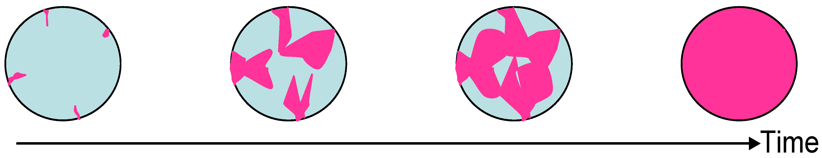
The conversion of a coal particle in an entrained flow gasifier is shown in Figure 27. The kinetic model to predict the burnout or total conversion of a coal particle in an entrained flow gasifier is
where: τ is the time for complete conversion ρB is the Coal particle density, 2 is the reciprocal of the stoichiometric coefficient for O2, kg is the mass transfer rate constant and C is the concentration of O2 [6].
Figure 27.
Bulk Diffusion Controlled Conversion in Entrained Flow Gasifiers.

These gasifiers can burn a fairly wide range of fuels when operated with a dry feed but are more limited when firing the fuel when fed as a slurry since a large amount of energy is required to vaporize the water in the slurry. Typical gas compositions for these gasifiers are presented in Table 8.
| Oxygen Blown | |||||
|---|---|---|---|---|---|
| Dry Bottom Moving Bed | Slagging Moving Bed | ||||
| Coal type | Brown/Lignite | Sub-Bit | Bit | Anth | Bit |
| Pressure atm | up to 92 | 25 | 24–100 | ~ | 21.0–32.0 |
| Gas Composition (Dry) | |||||
| CO | 17.4–19.7 | 15.1 | 15.2–19.5 | 22.1 | 55.0–61.2 |
| CO2 | 30.4–32.2 | 30.4 | 28.9–32.4 | 30.8 | 2.4–3.5 |
| H2 | 37.2–37.2 | 41.1 | 38.3–42.3 | 40.7 | 28.1–31.5 |
| N2 | 0.5–0.5 | 1.2 | 0.5–1.6 | 0.4 | 3.3–3.3 |
| CH4 | 11.8–12.1 | 11.7 | 8.6–10.1 | 5.6 | 5.0–8.3 |
| H2S | 0.1 | 0.5 | 0.8–1.1 | ~ | 1.3–1.3 |
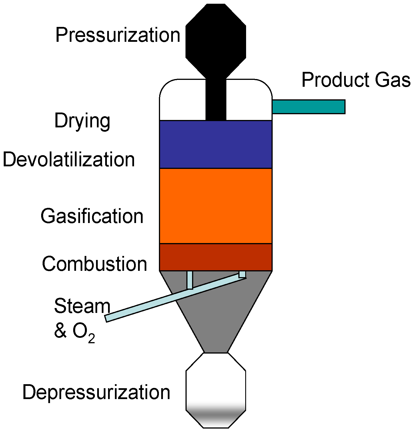
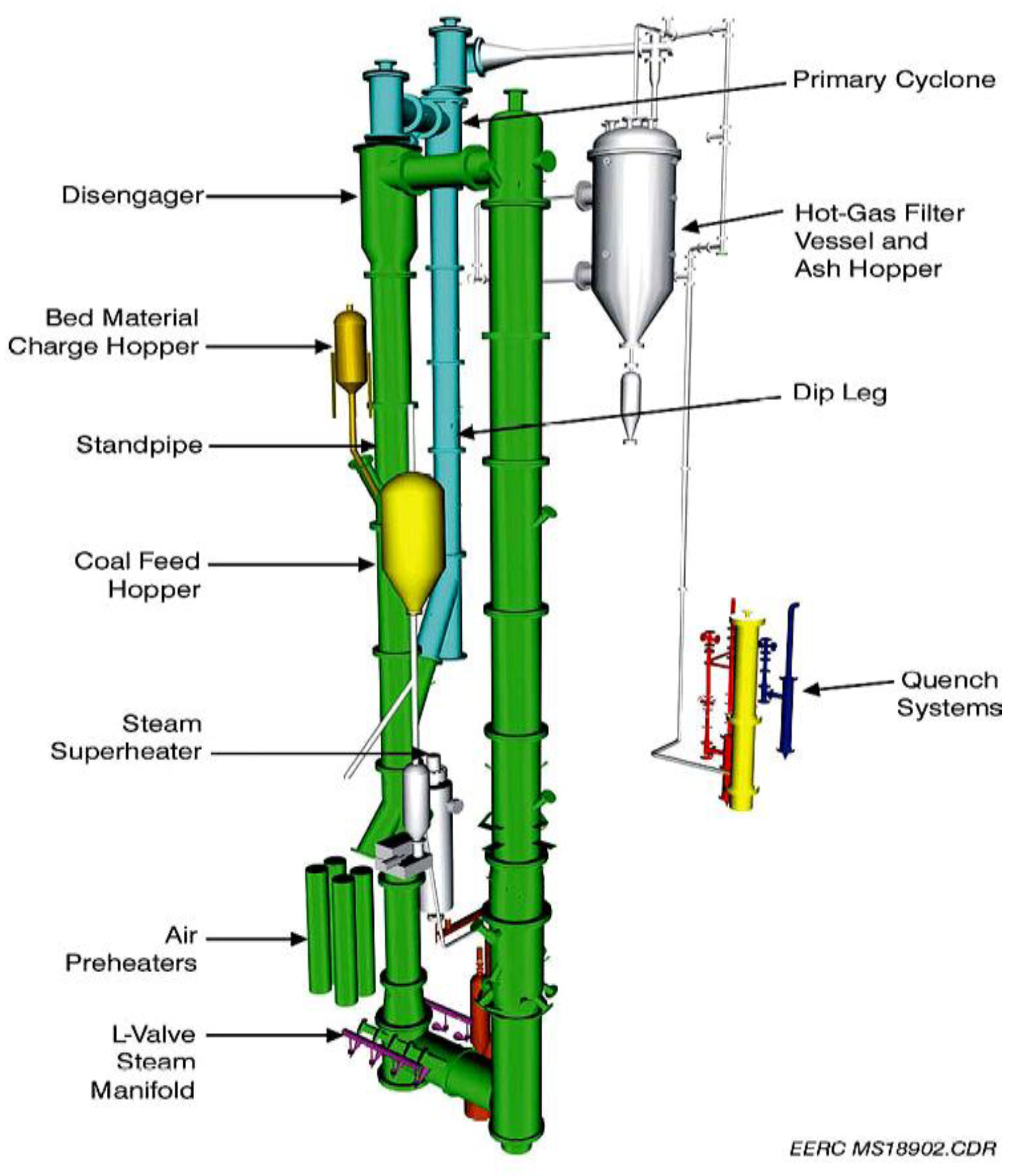
5.4. Transport Gasifier
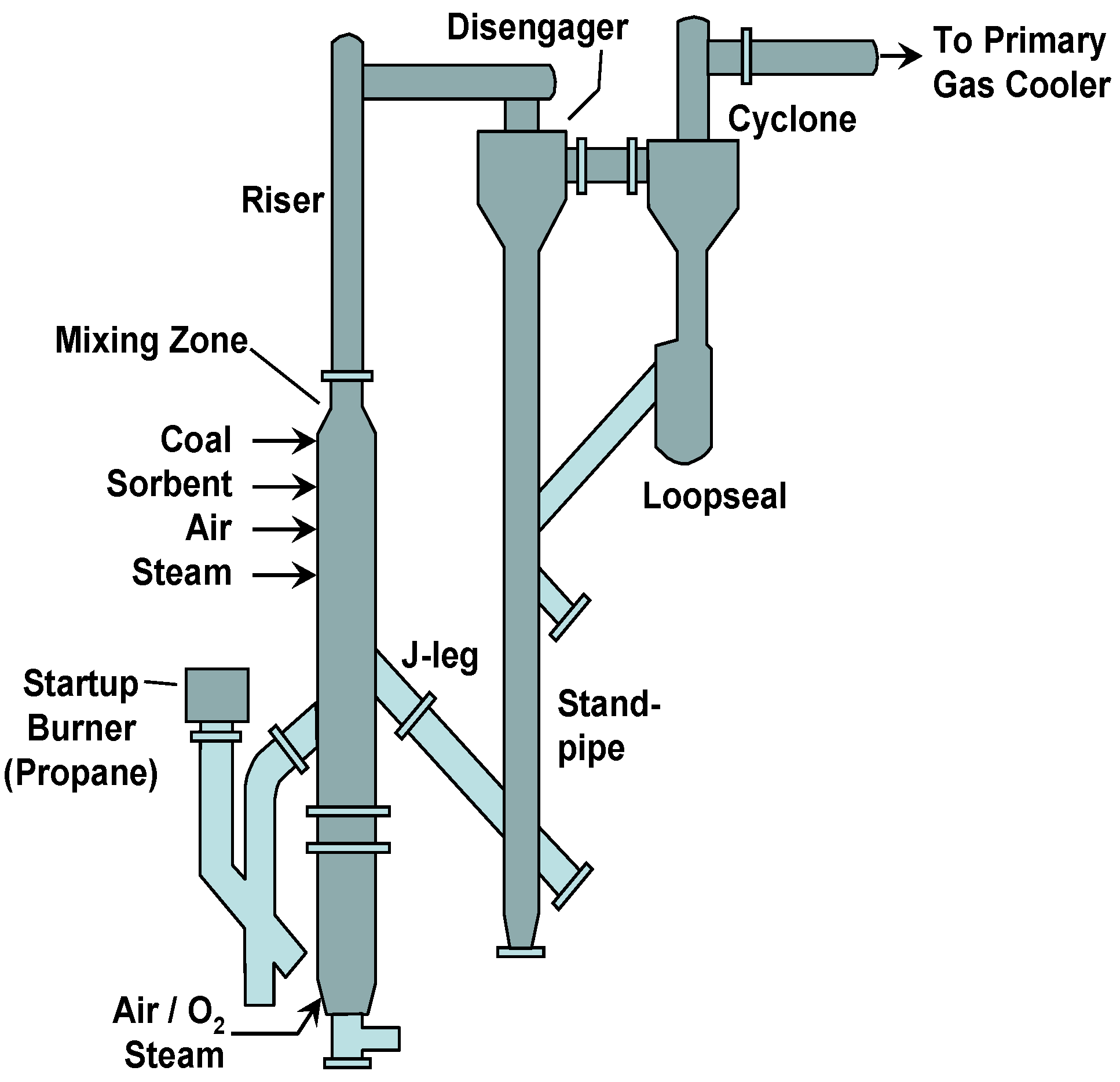
Kellogg, Brown and Root (KBR) is developing the transport gasifier at the Department of Energy’s (DOE’s) Power Systems Development Facility at Southern Company Services Wilsonville, Alabama plant. The transport gasifier (Figure 28) is based upon the hydrodynamic flow field that exists in KBR’s catalytic cracking technology. It has excellent gas-solids contact and very low mass transfer resistance between gas and solids. It has a highly turbulent atmosphere that allows for high coal throughput and high heat release rates at a low temperature that avoids problems with slag handling and liner erosion.
Figure 28.
KBR Transport Gasifier.
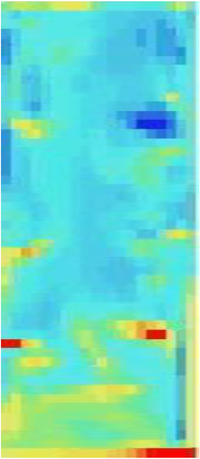
Hydrodynamically, transport reactors are circulating fluidized beds which have more complicated hydrodynamics than fixed bed reactors or bubbling fluidized beds have. In this type of reactor both excess gas and excess solids are fed to the reactor where the high gas velocity carries the solids upward. The excess solids tend to form clusters which act like large particles and fall back into the lower riser where they breakup and start to rise again. The results of an Eulerian-Eulerian simulation of the process is presented in Figure 29 where the deep blue is a gas void and the yellow and red areas are clusters moving down while the other solids are moving up. These reactors have better mixing of gas and solids leads to better inter-phase transport and better conversion of the coal. In addition, the mechanical movement of the solids against each other essentially scrubs the ash from particles.
Figure 29.
Clustering Riser Circulating Fluidized Bed Hydrodynamics.

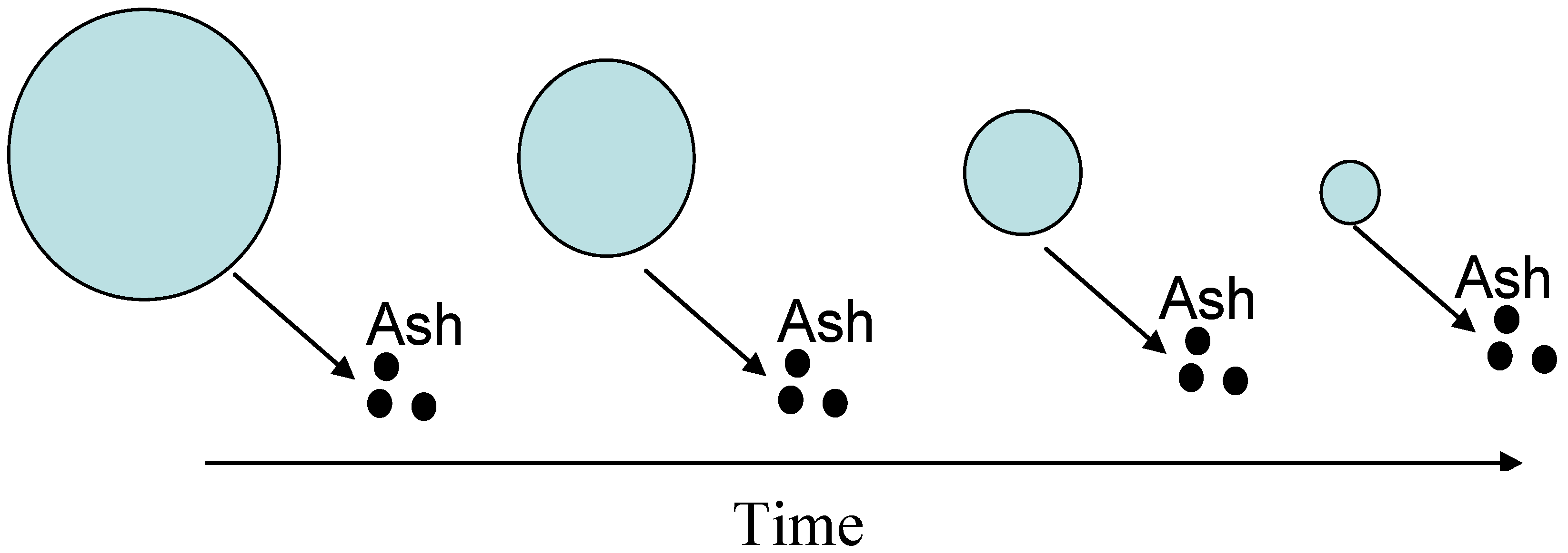
Kinetically, because of the scrubbing of the reacted layer, the burnout or conversion follows a shrinking particle as pictured in Figure 30. The conversion time can be calculated from the equation
where: τ is the time for complete conversion, ρB is the Coal particle density, 2 is 1/stoichiometric coefficient for O2, R is the particle radius, k is the combined kinetic and mass transfer rate constant, and C is the concentration of O2 [6].
Figure 30.
Particle Time History in Circulating Fluidized Bed Riser.

These units have moderate cold gas efficiencies and they accept a broad range of coals.
Typical gas compositions for thee different coals from the experimental facility are presented in Table 9.
Table 9.
Typical gas analysis from the Transport Gasifier Pilot Plant [11].
| Coal Type | Sub bituminous | Lignite | Bituminous | |||
|---|---|---|---|---|---|---|
| Mode | Air | Oxygen | Air | Oxygen | Air | Oxygen |
| Pressure, atm | 30 | 30 | 30 | 30 | 30 | 30 |
| Gas Composition (Dry) | ||||||
| CO | 23.7 | 39.1 | 18.8 | 37.9 | 13.3 | 25.5 |
| CO2 | 7.6 | 19.9 | 11.7 | 21.8 | 13.4 | 28.6 |
| H2 | 11.8 | 36.2 | 14.8 | 37.4 | 15.7 | 41.9 |
| N2 | 54.3 | 0.1 | 53.2 | 0.1 | 55.6 | 0.1 |
| CH4 | 2.6 | 4.8 | 1.6 | 2.9 | 2.0 | 3.9 |
References
- Overview of DOE’s Gasification Program, U.S. Department of Energy, Gasification Technologies Website. Available online: http://www.netl.doe.gov/technologies/coalpower/gasification/pubs/pdf/DOE%20Gasification%20Program%20Overview%202009%2009-03%20v1s.pdf (accessed on 20 September 2009).
- Hatheway, A.W. Personal communication, worldwide web site of (www.hatheway.net) dealing with 'Remediation of Former Manufactured Gas Plants & Other Coal Tar Sites'. Available online: http://www.hatheway.net/images/baltimore_bayard_station_large.jpg (accessed on 2 June,2009).
- Mark, M. Delivering performance in Chinese operations. In Proceedings of the Gasification Technologies Conference, Colorado Springs, CO, USA, October 2009.
- Higman, C.; van der Burgt, M. Gasification; Elsevier Science & Technology Books: London, UK, 2008. [Google Scholar]
- Seed, M.A.; Williams, A.R.; Brown, D.J.; Hirschfelder, H. Application of Slagging Gasification Technology to as received Lignite in China. In Proceedings of the Third International Conference on Clean Coal Technologies for our Future, Cagliari, Italy, May 2007.
- Levenspiel, O. Chemical Reaction Engineering, 3rd ed.; Wiley: New York, USA, 1998. [Google Scholar]
- Chem of Coal Util, Supl Vol.; Lowry, H.H. (Ed.) John Wiley: New York, USA, 1963.
- Chem of Coal Util, 2nd Supl Vol.; Elliot, M. (Ed.) John Wiley: New York, USA, 1981.
- Steam, 40th ed.; Stultz, S.C. (Ed.) Babcock and Wilcox: Barberton, OH, USA, 1992.
- Huang, J.; Fang, Y.; Chen, H.; Wang, Y. Coal gasification characteristics in a PFB. Energy Fuels 2003, 17, 1474–1479. [Google Scholar] [CrossRef]
- Smith, P. Personnel Communication for Test Results, Kellogg, Brown and Root: Houston, TX, USA, 2007.
© 2010 by the authors; licensee Molecular Diversity Preservation International, Basel, Switzerland. This article is an open-access article distributed under the terms and conditions of the Creative Commons Attribution license (http://creativecommons.org/licenses/by/3.0/).
Share and Cite
MDPI and ACS Style
Breault, R.W. Gasification Processes Old and New: A Basic Review of the Major Technologies. Energies 2010, 3, 216-240. https://doi.org/10.3390/en3020216
AMA Style
Breault RW. Gasification Processes Old and New: A Basic Review of the Major Technologies. Energies. 2010; 3(2):216-240. https://doi.org/10.3390/en3020216
Chicago/Turabian StyleBreault, Ronald W. 2010. "Gasification Processes Old and New: A Basic Review of the Major Technologies" Energies 3, no. 2: 216-240. https://doi.org/10.3390/en3020216