Article

A New Method Based on Thermal Response Tests for Determining Effective Thermal Conductivity and Borehole Resistivity for Borehole Heat Exchangers

1
Faculty of Drilling, Oil and Gas, Department of Drilling and Geoengineering, Laboratory of Geoenergetics, AGH University of Science and Technology (AGH UST), al. Mickiewicza 30, 30-059 Krakow, Poland
2
Faculty of Engineering and Applied Science, University of Ontario Institute of Technology, 2000 Simcoe Street North, Oshawa, ON L1H 7K4, Canada
3
Faculty of Mathematics and Natural Sciences, University of Rzeszow, Al. Rejtana 16c, 35-959 Rzeszów, Poland
*
Author to whom correspondence should be addressed.
Energies 2019, 12(6), 1072; https://doi.org/10.3390/en12061072
Submission received: 10 January 2019 / Revised: 16 March 2019 / Accepted: 17 March 2019 / Published: 20 March 2019

Abstract

:
Research on borehole heat exchangers is described on the development of a method for the determination, based on thermal response tests, of the effective thermal conductivity and the thermal resistivity for borehole heat exchangers. This advance is important, because underground thermal energy storage increasingly consists of systems with a large number of borehole heat exchangers, and their effective thermal conductivities and thermal resistivities are significant parameters in the performance of the system (whether it contains a single borehole or a field of boreholes). Borehole thermal energy storages provide a particularly beneficial method for using ground energy as a clean thermal energy supply. This benefit is especially relevant in cities with significant smog in winter. Here, the authors describe, in detail, the development of a formula that is a basis for the thermal response test that is derived from Fourier’s Law, utilizing a new way of describing the basic parameters of the thermal response test, i.e., the effective thermal conductivity and the thermal resistivity. The new method is based on the resistivity equation, for which a solution giving a linear regression with zero directional coefficient is found. Experimental tests were performed and analyzed in support of the theory, with an emphasis on the interpretation differences that stem from the scope of the test.

1. Introduction

A significant increase of new heating and heating/cooling installations that is based on heat pumps and borehole heat exchangers (BHE) has been recently observed in many countries, including Switzerland [1], Germany [2], Sweden [3], Canada [4], and the United States [5]. Borehole thermal energy storage (BTES) permits the extraction of heat from the ground for heating in winter and the extraction of cool (i.e., the input of heat) for air conditioning in summer [6,7]. A BTES is a type of geoenergetic system, which also includes energy systems that are based on geothermal waters. Geothermal energy utilisation is usually more problematic when it is connected with geothermal water rather than the ground.
The energy efficiency of a BHE mostly depends on the thermal conductivity of the underground rock mass. Other construction parameters also influence the energy efficiency. There are various types of BHEs, with the most typical being:
  • single U-tube;
  • multi U-tube;
  • coaxial [8,9];
  • helical [10,11]; and,
  • BHE in piles [12].
BHEs can be vertically drilled. Alternatively, the BHE construction technology of Geothermal Radial Drilling (GRD) allows for directional (oblique) wells [13]. GRD provides the possibility of using the ground under buildings for thermal energy storage by the placing of boreholes. The effectiveness for various BHEs of different constructions has been compared. For instance, the effective thermal conductivity and performance in closed-loop vertical ground heat exchangers have been compared [14] and evaluated with TRTs [15], while the performances of the U-tube, concentric tube, and standing column well ground heat exchangers have been compared while using simulation [16]. Additionally, the thermal performances have been assessed for various types of underground heat exchangers [17] and for borehole heat exchangers specifically using TRTs [18]. The latter study included an analysis and comparison of interpretation methods.
BTES efficiencies in the literature consider such factors as borehole array geometry [19], heat transfer from the surroundings [20,21], grout parameters [22], freezing of underground water [23], and underground water flow. Studies that account for underground water flow include examinations of the influence of groundwater on: pile geothermal heat exchanger with cast-in spiral coils [24], closed-loop ground-source heat pump systems [25], the heat transfer in ground heat exchangers [26], the optimization of large-scale ground-coupled heat pump systems [27] and vertical closed-loop geothermal systems [28], the simulation of borehole heat exchangers [29], and the performance of geothermal heat exchangers [30]. Reference [31] describes many factors concerning coaxial BHEs.
The thermal response test (TRT) is an accurate and conventional method for the determination of the thermal properties of different cases of borehole heat exchangers [32]. A TRT is typically performed in large installations (over 100 kW) for an exploration BHE. According to [33], the TRT is an economic test for a lower capacity limit of about 30 kW. When the thermal parameters of the analyzed borehole heat exchanger are known, it is possible to establish the number of boreholes that are needed to satisfy heating and/or cooling demands.
Much work is being carried out to improve TRTs. For instance, a distributed TRT approach is described in [34]. The measuring process during a disturbed TRT (i.e., one with thermal sensors inside the BHE) affects the results. Sensors inside a BHE cause local turbulences and pressure losses, rendering the measuring unsettled/distorted. New methods for the interpretation of TRT results using statistics are described in [35,36]. The factors that are considered in a TRT are described in [37], for example, outdoor air temperature. Error analysis for a TRT is described in [38].
A TRT can be performed using various methods, e.g., the method that is described by Eskilson [39] and the computer code Earth Energy Designer (EED), which was developed following that method. Additionally, the extent of an underground thermal energy storage, i.e., the number and distribution of borehole heat exchangers, can be determined with numerical modeling, e.g., [40] or with commercial simulators [41].
Thermal response tests and mathematical modeling can also be used for determining the energy efficiency for thermal purposes of oil and gas wells, which have the potential for conversion to borehole heat exchangers [42]. This application has attracted increasing interest in recent years, especially for deep borehole heat exchangers, and it has correspondingly been subject to analysis by energy specialists in academe and industry.
BHE modeling also needs to account for thermal stresses. Doing so is essential for large installations that are connected with thermal waters and heat recovery from enhanced geothermal systems [43,44] and large BHE fields. The methods of thermal stress calculation that are used in the oil and gas industry can be applied for geothermal wells (and BHEs) [13].
In this article, we propose and verify a new method of establishing effective thermal conductivity of BHEs and assessing the usefulness of this method for utilization with thermal response tests. Existing methods provide the BHE thermal resistivity (Rb) as a function of the time of the TRT, whereas it should be constant in time. The method that is proposed here rectifies this shortcoming. That is, it is often possible to observe a change in Rb with time during a TRT [45]. Sometimes the change is an increase and at other times a decrease. Since the formula includes the effective thermal conductivity of the BHE (λeff), the value of λeff can be found, which yields a constant function Rb with time.
The novelty of this article lies in it presenting a new enhancement to a methodology. The methodology is described in the paper and verified while using the analyses of two TRTs. The main contribution and scientific significance is that it assists efforts to interpret TRTs better, so as to avoid tests providing erroneous or problematic results. Problematic TRTs occur quite often in practice.
The proposed new approach is based on the equation for the thermal resistivity of a BHE Rb in the function of the thermal conductivity of a rock mass λ or effective thermal conductivity λeff, as determined on the basis of a TRT. The new methodology is based on the assumption that Rb does not depend on the duration of the TRT, an assumption that corresponds to reality.
The basic assumption of the new approach can be expressed by the formula Rb = f(t) = constant. The equation Rb = f(t) can be developed into the dependence of Rb = kt + b. According to the model assumption kt + b = constant, the equation is spilled if and only if k = 0. The determination of thermal conductivity λx and BHE thermal resistivity Rb is reduced in this methodology to determining such a value of λx, to obtain k = 0. Subsequently, we get Rb = b.

2. Thermal Response Test Mathematical Background

According to the well-established Kelvin infinite line source theory thermal response test was developed [46]. The TRT methodology is based on the partial differential equation form of the Fourier thermal conductivity equation, which describes the dynamic dependence of temperature T on the distance from heat exchanger r and duration of the test t, i.e., determines T = T ( r , t ) . The equation has the following form:
2 T r 2 + 1 r T r = ρ c p λ T t
One method of solving such a partial differential equation involves substitution. This transforms the partial differential Equation (1) to an ordinary differential equation. Perina [47] has used this approach to describe the Theis equation in hydrogeology, which gives the pressure distribution p = p(r,t). To use this approach, we let
u = r 2 ρ c p 4 t λ
and
ρ c p = λ α
Subsequently, we can show that
u = r 2 4 α t
and Equation (1) assumes the following form:
2 T r 2 + 1 r T r = 1 α T t
Returning to the Substitution (4), we finally obtain
T ( r , t ) = T 0 + q k π λ r 2 4 α λ e x x d x
In view of the substitution in Equation (4), and by substituting the integral in (6) with an approximate expression, we obtain
T ( r , t ) = T 0 + q 4 π λ [ ln ( 4 α t r 2 ) γ ]
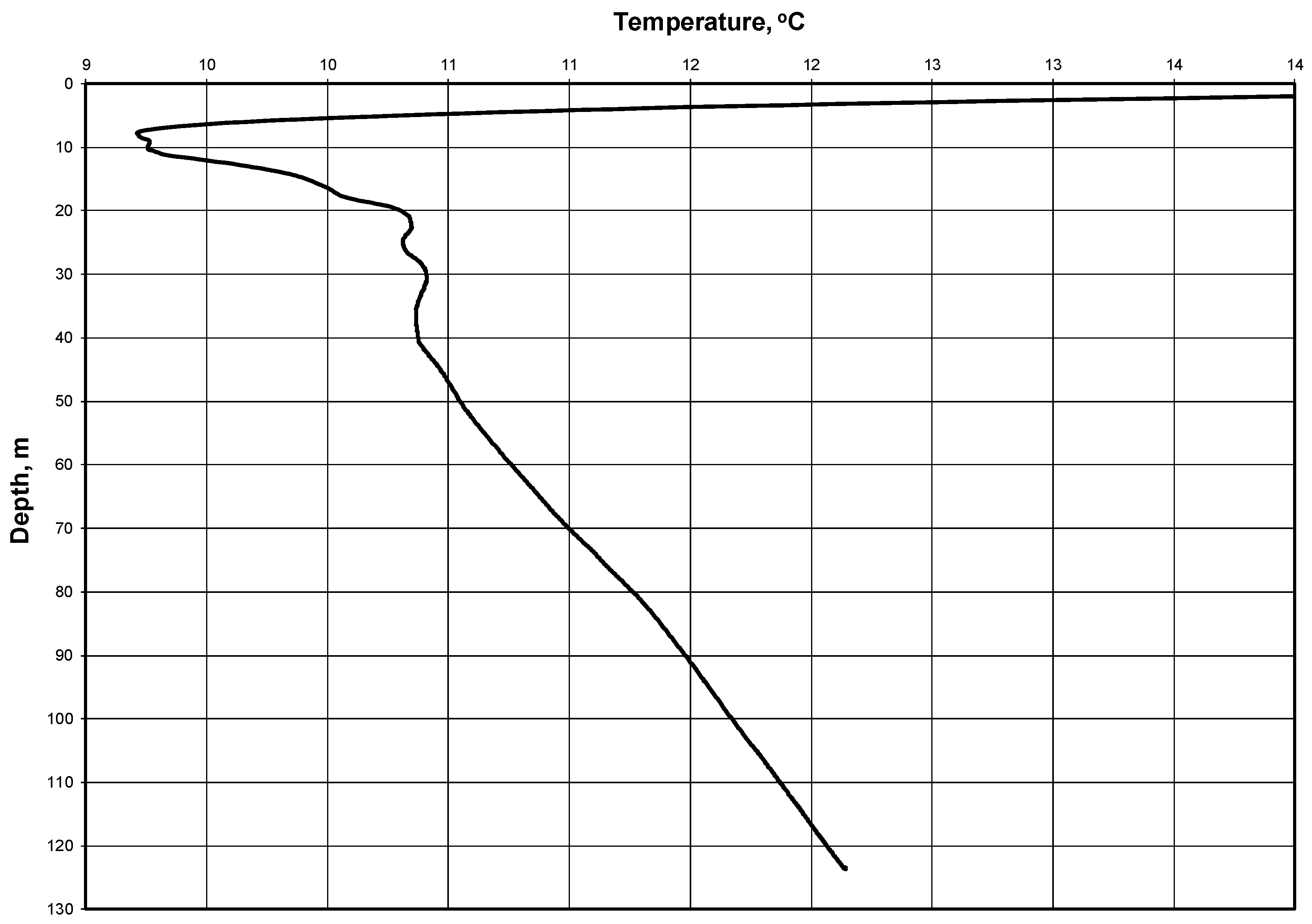
Regarding initial and boundary conditions, it is noted that the solution obtained is not numerical. Rather, it is analytical and the idea of the mathematical model of the TRT is based on an infinite linear heat source. Accordingly, we do not solve the differential equation in a finite region. The (linear) source has a length that corresponds to the borehole depth. The time of the TRT is limited (max. 100 h). The initial temperature corresponds to the natural temperature distribution, as seen in Figure 1, but it is normally approximated with one initial temperature: To.

3. Two Thermal Response Tests

The Thermal Response Test (TRT), which is sometimes called the Geothermal Response Test (GRT), is a suitable method in determining the effective thermal conductivity of the ground and the borehole thermal resistance (or the thermal conductivity of the borehole fill). A temperature curve is obtained, which can be evaluated by several methods. The resulting thermal conductivity is based on the total heat transport in the ground. Other effects, like convective heat transport (in permeable layers with groundwater), and further disturbances are automatically included, so it may be more correct to speak of an “effective” thermal conductivity 
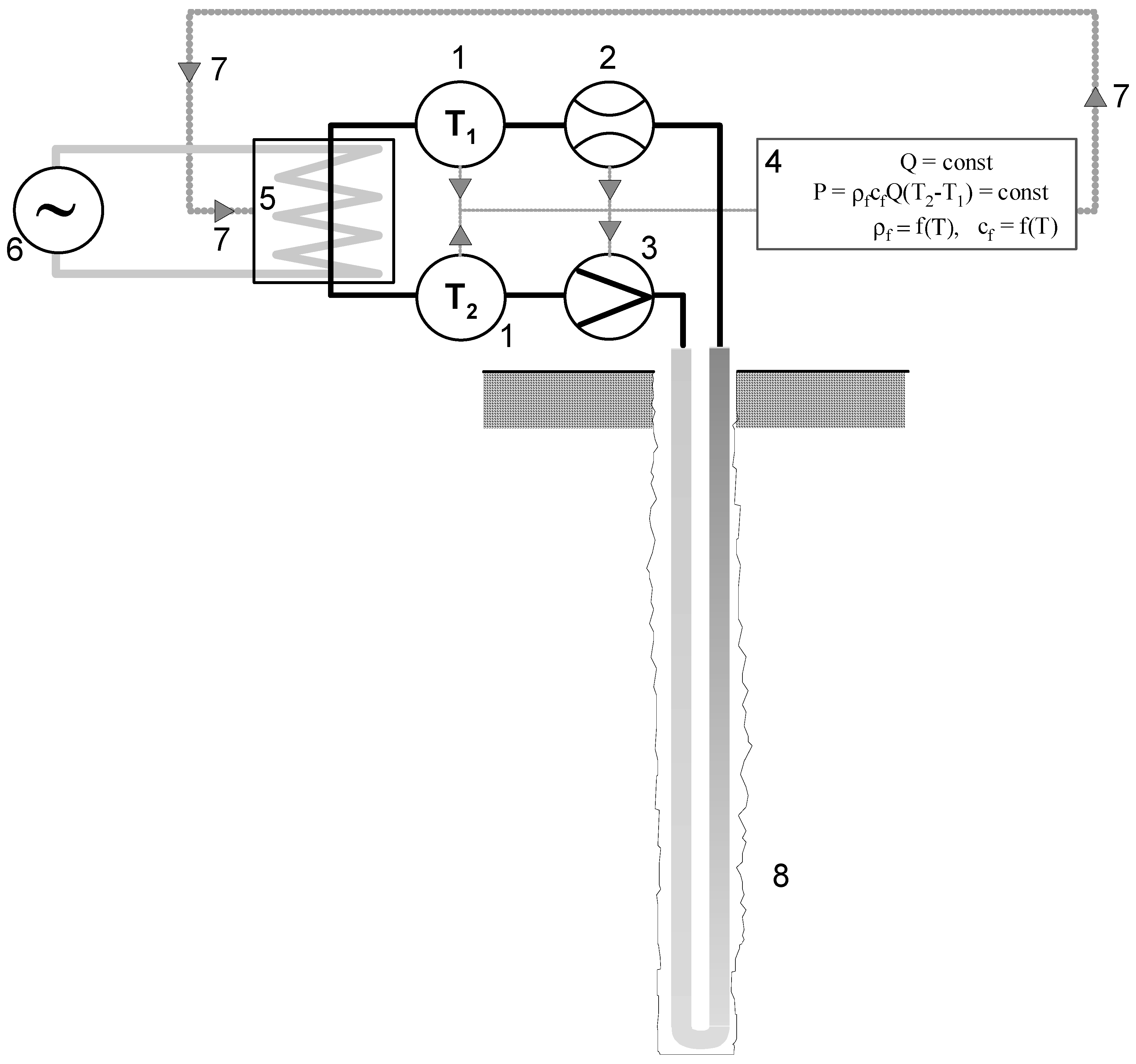
λeff. The test equipment can be made in such a way that it can be easily transported to the site, e.g., on a light trailer (Figure 2) [48]. In short, a TRT relies on forcing the closed circulation of a heat carrier that is heated with a constant heating power. The temperature change with time is analyzed.
The TRT involves introducing and collecting energy from a borehole heat exchanger (Figure 2). During the tests, the heat carrier is most frequently heated at a constant heating power P, which is measured, and the temperatures T1 and T2 are then recorded. The heating power is maintained by switching the heaters on and off. The automation system takes into account the variability with the temperature of the heat carrier density ρ and the specific heat at constant pressure cp.
This section describes two actual thermal response tests. The Laboratory of Geoenergetics, Faculty of Drilling, Oil, and Gas, AGH University of Science and Technology in Krakow, Poland performed the tests and analyses [49,50]. The tests were carried out to illustrate and compare the results from the old and new methods of TRT interpretation.
For the sake of interpretation, it is noted that the TRT was performed for a borehole heat exchanger, the geological profile of which is presented in 
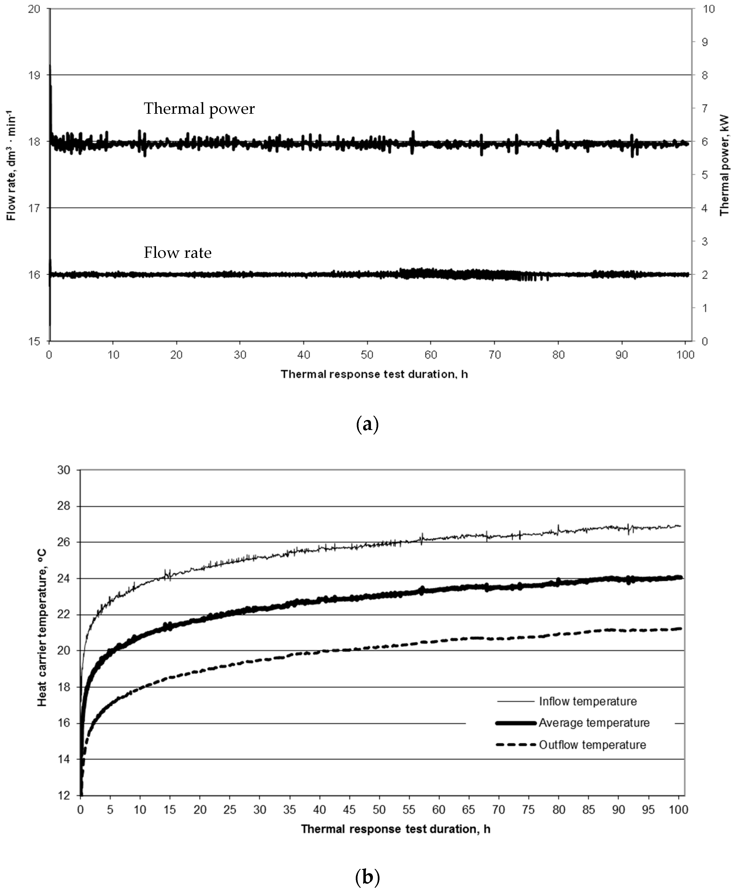
Table 1. The first test was performed in Żarów (Dolnośląskie Region, Poland) in 2011. The average heating power during the test was P = 5920 W and the volumetric flow rate of the carrier was 16 dm3∙min−1 (Figure 3a). The control of the volume value of the heat carrier volumetric flow rate was carried out with a rotary (windmill) flowmeter with an accuracy of 0.25 dm3 per one impulse. The flow measurements have the task of only visual control of the correctness of the TRT execution, where the relationship Q = const should be satisfied. Similarly, for the value of heating power P, which is calculated on the basis of temperature measurements from the dependence P = QρcΔT, the visual relationship (Figure 3a) should be observed during the entire test to ensure P = const.
The borehole heat exchanger is H = 120 m deep, so the heat exchange per unit of depth is q = 49.34 W·m−1. In the linear heat source model, the unit heating power is assumed to be uniform. A constant temperature is also assumed in the model for the heat carrier and the ground. Table 2 presents the design of the borehole heat exchanger.
A second TRT was performed in the BHE at the Laboratory of Geoenergetics in the university, where the lithological profile is as described in Table 3.
The values of Do, dz, Hb, b, and H (in Equation (8)) in Table 2 were provided by a company making a BHE without any data on measurement accuracy. The value of λg comes from the literature [51].
Figure 3b presents the curves illustrating the data during the TRT test, where the dependence on the duration of the test is observed. The average thermal conductivity that is assumed for rocks of 2.15 W·m−1·K−1 is based on data in the literature [51], as is the average volumetric specific heat of rocks in the profile of 2.17 MJ·m−3·K−1 [52,53]. A 35% propylene glycol solution is used as the heat carrier. At 20 °C, the specific heat of the carrier is 3810 J∙kg−1·K−1 and its density is 1028 kg∙m³.
The average temperature of the rock mass is determined on the basis of the heat carrier circulation, without heating (i.e., before the TRT heating phase begins). The return flow temperature is 11.1 °C and the mean measured air temperature is 16.1 °C. The mean natural temperature in the borehole can also be determined on the basis of temperature logging [54]. The mean temperature of the rock mass, based on the temperature profile (Figure 1), is 11.00 °C. The NIMO-T (Non-wired Immersible Measuring Object for Temperature) was used for temperature profiling in BHE. The relative error of the temperature measurement was 0.0015 °C and the absolute error was 0.1 °C [54].
The thermal diffusivity α = 0.97·10−6 m²·s−1 is calculated using data from the literature [51] and Equation (3).
The mean temperature of the heat carrier flowing into the BHE during the test is 25.48 °C and the mean return flow temperature is 19.82 °C. Thus, the mean temperature difference is 5.67 °C and the mean temperature of the heat carrier is 22.65 °C.
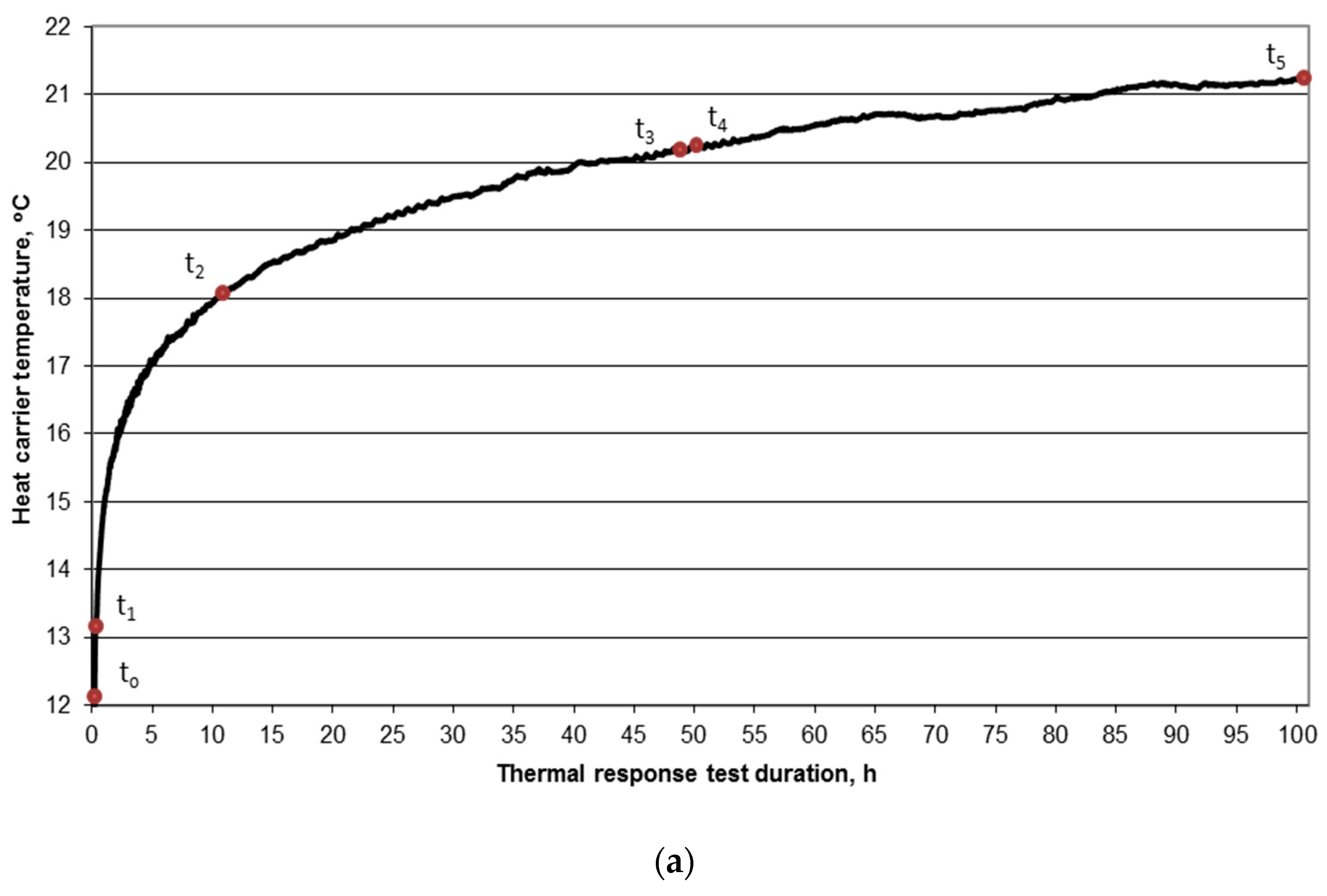
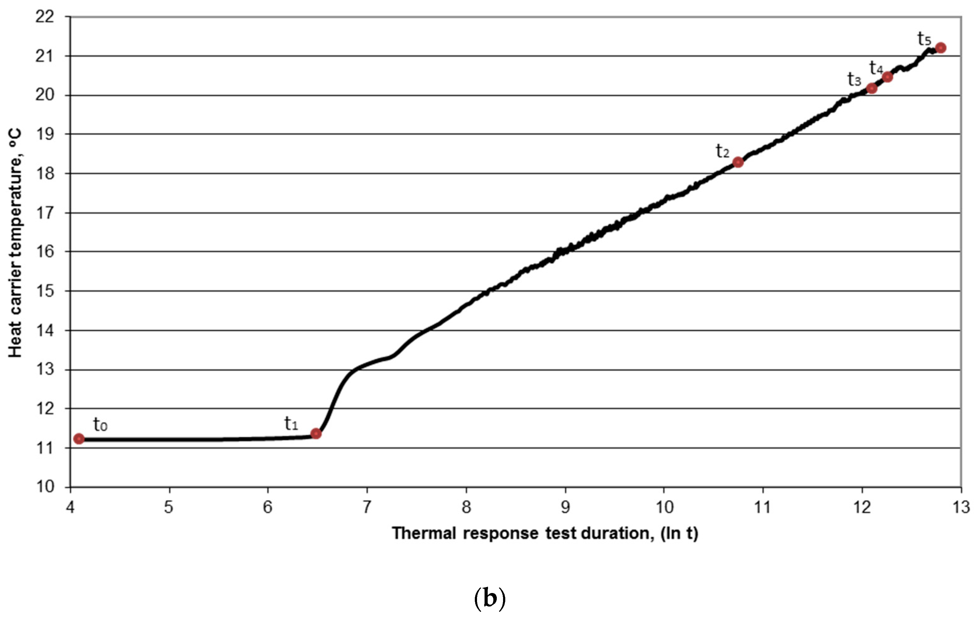
Figure 4 shows the characteristic times that are used for the interpretation of TRT results. There, the points are denoted, as follows: t0 the beginning of heating phase of the test (heaters on), t1 the slope point of the curve (time of the first complete circulation loop of the heat carrier), t2 the time corresponding to t = 5   r o 2 α 1 , t3 the time corresponding to t = 20   r o 2 α 1 , t4 the half-time of the heating phase of the test, and t5 the end of the heating phase of the test (heaters off).
The following values were obtained during the test: t0 = 0, t1 = 480 s (0.13 h), t2 = 46348 s (12.87 h), t3 = 185391 s (51.50 h), t4 = 180660 s (50.18 h), and t5 = 361320 s (100.37 h). Linear regression analysis is used for determining coefficients of line slope in the semi-logarithmic system (log t) for the following time intervals:
  • from t0 to t5
  • from t1 to t5
  • from t2 to t5
  • from t0 to t2
  • from t0 to t3
  • from t2 to t3
  • from t1 to t4
  • from t3 to t5.
The values of the slope coefficient k and the effective thermal conductivity λeff are calculated on the basis of Equation (7), as follows:
λ e f f = P 4 π H k = q 4 π k
Table 4 lists the results, including the average values of the BHE thermal resistivity Rb and values for various data intervals. The value of Rb is calculated, as follows:
R b = 1 q [ T a v ( t ) T 0 ] 1 4 π λ [ ln 4 α t r o 2 γ ]
Here, values for λ can be taken from the literature (λ = 2.15 W∙m−1∙K−1 from Table 1) or calculated with Equation (7).
In Table 5, the TRT results are shown for a BHE belonging to the Laboratory of Geoenergetics, Faculty of Drilling, Oil, and Gas AGH–University of Science and Technology for a heat carrier volumetric flow rate of 12 dm3·min−1 and heating power P = 4000 W. The lithological profile of the borehole was described earlier (Table 5), as was the design of the borehole heat exchanger (Table 2).
The correlation coefficient for two TRTs was calculated. It concerned the temperatures dependence of the heat carrier and the duration of TRT. In both cases, the correlation coefficient had a higher value than 0.925.

4. A New Way of Determining Parameters from TRTs

Although the test (Figure 3b) was carried out almost ideally, there are discrepancies in the BHE thermal conductivity and thermal resistivity values. These discrepancies stem from the different ranges of data that are assumed for the analyses. Therefore, a new way of determining the parameters λeff and Rb is proposed.
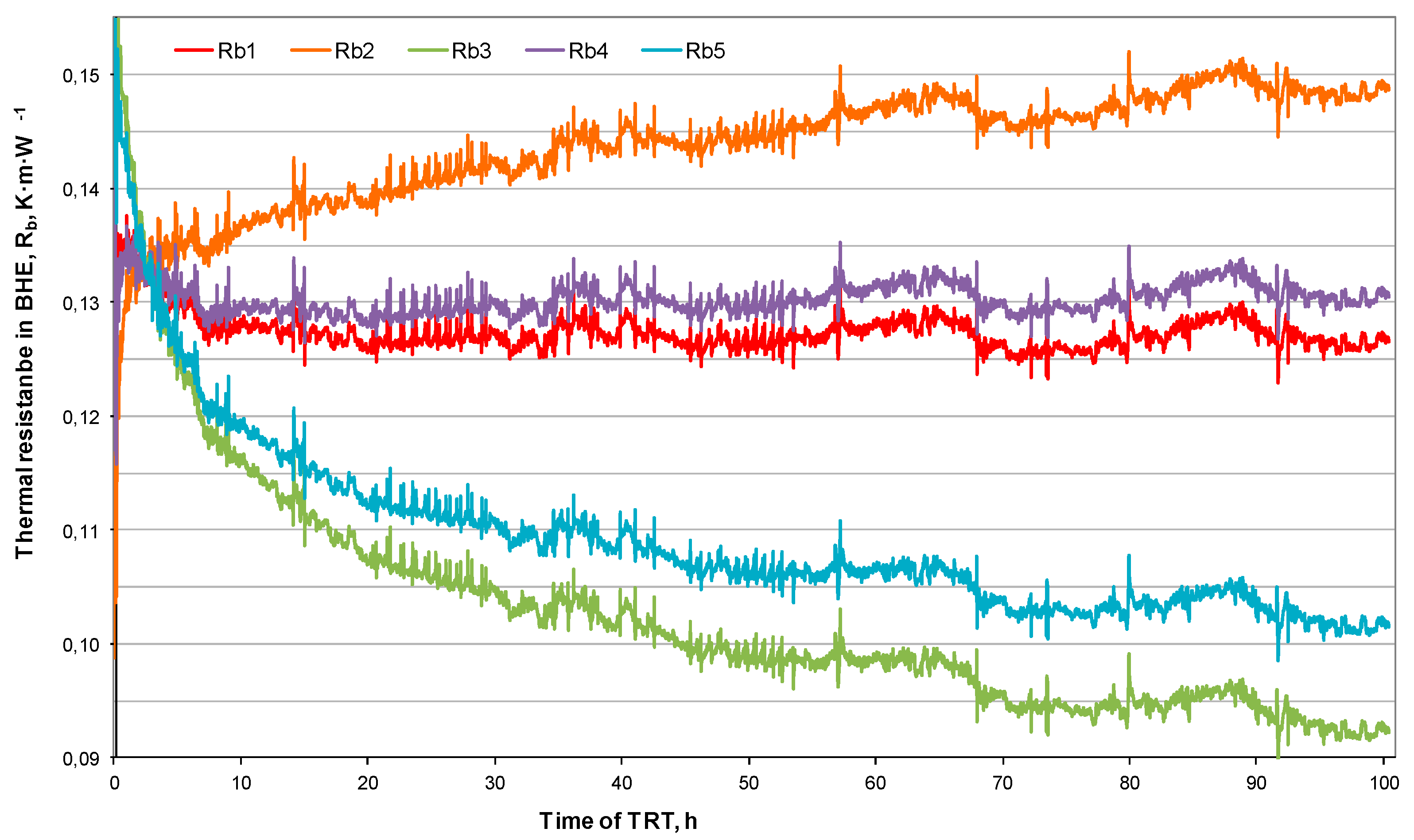
Figure 5 presents a graph showing the dependence of BHE thermal resistivity on test duration. The curves for Rb1 and Rb4 are more ‘linear’ in Figure 5 than the curves for Rb2, Rb3, and Rb5. Both of the curves only differ in the value of λ from Equation (8).
The proposed approach involves determining a value of λ for which linear regression that is based on Rb = f(t) assumes the form of a function Rb = kt + b with a slope coefficient k of zero. The task of determining λ and Rb values reduces to finding a λ value, for which k = 0, after which we have Rb = b. For the TRT that was performed in Żarów, we determined the following pairs of values meeting this requirement: λeff = 2.77 W·m−1·K−1 and Rb = 0.129 m·K·W−1. This contrasts with the values obtained with the traditional method of λ = 2.81 W·m−1·K−1 and Rb = 0.130 m·K·W−1.
For the TRT performed at the BHE of the Laboratory of Geoenergetics, we find λ = 1.98 W·m−1·K−1 and Rb = 0.134 m·K·W−1 (whereas with the traditional method λ = 1.97 W·m−1·K−1 and Rb = 0.128 m·K·W−1).
Figure 5 shows the relation of Rb with time from the TRT for the test in Żarów. The curves of Rb = f(t) only vary due to the value of λ in Equation (9). The waveforms represent the following:
  • Rb1–graph of BHE thermal resistance vs. time for the conductivity λeff calculated for data from a time equal 5r02∙α−1 to the end of the heating phase of TRT (λeff = 2.70 W∙m−1∙K−1)
  • Rb2–graph of BHE thermal resistance vs. time for the conductivity λ = 125% λeff (λ = 3.37 W∙m−1∙K−1);
  • Rb3–graph of BHE thermal resistance vs. time for the conductivity λ = 75% λeff (λ = 2.03 W∙m−1∙K−1);
  • Rb4–graph of BHE thermal resistance vs. time for the conductivity when linear regression yields a constant function (for which k = 0 in the function Rb = kt + b), according to the new method described above (λ = 2.80 W∙m−1∙K−1); and,
  • Rb5–graph of BHE thermal resistance vs. time for the conductivity based on data in the literature, as in Table 1 (λ = 2.15 W∙m−1∙K−1).
The values of Rb and λeff for various time intervals calculated based on the new methodology are listed in the Table 6 for the TRT at Żarów and in Table 7 for the TRT at the Laboratory of Geoenergetics.

5. Results and Discussion

The thermal response test is the most favored way of determining the basic BHE parameters. The effective thermal conductivity λeff is the most important value for characterizing a BHE, and it is used for determining its energy efficiency. The effective thermal conductivity is mainly dependent on the thermal conductivity of rocks λ, especially when the BHE has been correctly performed. In reality, λeff is also dependent on the heat transfer resistivity between the heating agent circulating in the BHE and the rock mass. This heat transfer resistivity accounts for:
  • transfer of heat from the heating agent to the material (most frequently U-tubes), which depends on, among other factors, its viscosity;
  • heat conduction through the material (U-tube), which is affected by its thermal conductivity, e.g., for the case of a polyethylene tube λ = 0.42 W·m−1·K−1;
  • heat flow between the material of U-tube and the BHE filling/sealing material, where discontinuities may occur; and,
  • Heat flow between the BHE filling/sealing material and rock mass, where some discontinuities may be encountered.
An analysis of the experimental and analytical results reveals that, despite a correctly performed TRT, the values of λeff are not constant with the time of test. This is caused by the assumed duration of the test. Such differences with respect to the value that was obtained for the full time of the test (100 h) may as great as 16.50%, relative to the traditional method (Table 5), and 9.69% for the new method (Table 7). The greatest percentage difference between the values of λeff and Rb are underlined in bold in Table 4, Table 5, Table 6 and Table 7. The relative change of Rb or λeff with respect to the full measurement range is calculated in %, relative to the values in the first time interval (t0 to t5). Accordingly, the percentage difference for this interval (i.e., the full range of data, t0 to t5) is always zero.
The new method is observed to be more accurate and stable in time for calculating the effective thermal conductivity λeff in BHEs. However, when analyzing the BHE thermal resistivity Rb, larger discrepancies can be observed for relative deviations from the basic value (for the full test duration). A maximum deviation of 1.80% for the traditional method (Table 5) and 9.70% for the new method is observed (Table 7). The greatest differences are observed for the TRT performed at the Laboratory of Geoenergetics, Faculty of Drilling, Oil, and Gas, AGH University of Science and Technology. For TRTs performed in Żarów, the corresponding deviations are much smaller. Therefore, more analyses of TRT data are needed while using the new methodology to assess these discrepancies, and that is the topic of ongoing research by the authors.
Many more analyses of TRT results are needed, along with the corresponding statistical analyses, to choose a better method for the interpretation of TRT results. In practice, there is no ideal TRT. The functional variation of temperature with time has many distortions. Simultaneously with improving TRT interpretations, the TRT measuring procedure also needs improvement. The inflow of material at the outside temperature should be reduced/eliminated, and a reliable automatic system is needed for maintaining a constant heating power when the variable voltages are present in the electrical network. Both of these requirements are being addressed at the Laboratory of Geoenergetics.
The accuracy of the calculation of the effective thermal conductivity coefficient and the thermal resistance has not been extensively examined in this article. That is because the target of this article is to describe the new methodology. Research by the present authors is ongoing to assess the precision of the results that were obtained with the new method, and it is expected to be reported soon.

6. Conclusions

The thermal response test is the most accurate way of determining parameter values of borehole heat exchangers. The effective thermal conductivity λeff and thermal resistivity of borehole Rb can be used in the design of an appropriate number of borehole exchangers for a given heating power demand and for a given time duration.
However, when interpreting the thermal response test, there are sometimes problems with the resulting values. That is, the values of thermal conductivity λeff and thermal resistivity Rb can differ depending on the assumed range of data, especially the time data. Various values of basic parameters are seen to be obtained, even for correctly performed tests, when analyzing various TRT time intervals.
The proposed method of determining basic TRT parameters is based on the BHE thermal resistivity Rb equation. This dependence (Equation (9)) is also observed to be a function of effective thermal conductivity λeff of the borehole heat exchanger. It is suggested that, a pair of the test results, i.e., effective thermal conductivity λeff and BHE thermal resistivity Rb, can predict the dependence of resistivity as a function of time, such that the slope coefficient of the regression line that is based on this approach is zero.
It is concluded from the analyses that the proposed new method of determining the values of the basic parameters of a BHE is more accurate and independent of thermal response test duration. The differences that were obtained for various TRT times with the proposed method for λeff are lower than with the traditional method. However, larger differences are obtained for Rb. Further work to assess the usefulness of this method in the interpretation of TRT data appears to be merited.

Author Contributions

Conceptualization, A.S.-S., A.G. and M.A.R.; methodology, A.S.-S.; software, T.S.; validation, A.S.-S. and T.S.; formal analysis, J.K.; investigation, T.S.; resources, A.S.-S. and A.G.; data curation, T.S.; writing, reviewing and editing of manuscript, A.S.-S., T.S. and M.A.R.; visualization, T.S.; supervision, A.S.-S.; project administration, A.S.-S.; funding acquisition, A.S.-S. and T.S.

Funding

This research was funded by statutory research programme at the Faculty of Drilling, Oil and Gas, AGH University of Science and Technology in Krakow, Poland, grant number 11.11.190.555.

Conflicts of Interest

The authors declare no conflict of interest.

Nomenclature/Glossary

bthickness of pipe of U-tube (mm)
cpspecific heat at constant pressure of ground (J kg−1 K−1)
cfspecific heat of heat carrier (J kg−1 K−1)
Doborehole diameter (m)
dzouter diameter of pipe of U-tube (m)
Hdepth of BHE (m)
Hbdepth of borehole (m)
ktheoretical directional factor of TRT
Pthermal power of TRT (W)
qunit thermal power (W m−1)
Qflow rate of heat carrier (m3·s−1)
rradial distance from vertical axis of borehole heat exchanger (m)
roborehole heat exchanger radius (m)
RbBHE thermal resistivity (m K W−1)
Ttemperature of ground (K)
Toinitial temperature (K)
Tavmean temperature of heat carrier in BHE during TRT (K)
T1temperature of heat carrier (outflow from BHE) (K)
T2temperature of heat carrier (inflow to BHE) (K)
ttime (s)
uvariable
αthermal diffusivity of ground (m2 s−1)
λthermal conductivity of ground (W m−1 K−1)
λeffeffective thermal conductivity in BHE (W m−1 K−1)
λxthermal conductivity obtained by new method (W m−1 K−1)
λgthermal conductivity of grout (gravel) (W m−1 K−1)
ρdensity of ground (kg m−3)
ρfdensity of heat carrier (kg·m−1)
γEuler constant (γ = 0.5772156)
ΔTmean temperature difference T2T1 (K)

References

  1. Rybach, L.; Eugster, W.J. Sustainability aspects of geothermal heat pump operation, with experience from Switzerland. Geothermics 2010, 39, 365–369. [Google Scholar] [CrossRef]
  2. Weber, J.; Ganz, B.; Schellschmidt, R.; Sanner, B.; Schulz, R. Geothermal energy use in Germany. In Proceedings of the World Geothermal Congress, Melbourne, Australia, 19–25 April 2015. [Google Scholar]
  3. Gehlin, S.; Andersson, O.; Bjelm, L.; Alm, P.G.; Rosberg, J.E. Country update for Sweden. In Proceedings of the World Geothermal Congress, Melbourne, Australia, 19–25 April 2015. [Google Scholar]
  4. Raymond, J.; Malo, M.; Tanguay, D.; Grasby, S.; Bakhteyar, F. Direct utilization of geothermal energy from coast to coast: A review of current applications and research in Canada. In Proceedings of the World Geothermal Congress, Melbourne, Australia, 19–25 April 2015. [Google Scholar]
  5. Boyd, T.L.; Sifford, A.; Lund, J.W. The United States of America country update 2015. In Proceedings of the World Geothermal Congress, Melbourne, Australia, 19–25 April 2015. [Google Scholar]
  6. Dincer, I.; Rosen, M.A. Thermal Energy Storage: Systems and Applications, 2nd ed.; Wiley: London, UK, 2011. [Google Scholar]
  7. Kizilkan, O.; Dincer, I. Borehole thermal energy storage system for heating applications: Thermodynamic performance assessment. Energy Convers. Manag. 2015, 90, 53–61. [Google Scholar] [CrossRef]
  8. Sliwa, T.; Rosen, M.A. Natural and artificial methods for regeneration of heat resources for borehole heat exchangers to enhance the sustainability of underground thermal storages: A review. Sustainability 2015, 7, 13104–13125. [Google Scholar] [CrossRef]
  9. Beier, R.A.; Acuña, J.; Mogensen, P.; Palm, B. Borehole resistance and vertical temperature profiles in coaxial borehole heat exchangers. Appl. Energy 2013, 102, 665–675. [Google Scholar] [CrossRef]
  10. Zarrella, A.; De Carli, M. Heat transfer analysis of short helical borehole heat exchangers. Appl. Energy 2013, 102, 1477–1491. [Google Scholar] [CrossRef]
  11. Zarrella, A.; Capozza, A.; De Carli, M. Analysis of short helical and double U-tube borehole heat exchangers: A simulation-based comparison. Appl. Energy 2013, 112, 358–370. [Google Scholar] [CrossRef]
  12. Li, M.; Lai, A.C.K. Heat-source solutions to heat conduction in anisotropic media with application to pile and borehole ground heat exchangers. Appl. Energy 2012, 96, 451–458. [Google Scholar] [CrossRef]
  13. Knez, D. Stress State Analysis in Aspect of Wellbore Drilling Direction. Arch. Min. Sci. 2014, 59, 69–74. [Google Scholar] [CrossRef]
  14. Lee, C.; Moonseo, P.; Sunhong, M.; Shin-Hyung, K.; Byonghu, S.; Hangseok, C. Comparison of effective thermal conductivity in closed-loop vertical ground heat exchangers. Appl. Therm. Eng. 2011, 31, 3669–3676. [Google Scholar] [CrossRef]
  15. Lee, C.; Moonseo, P.; The-Bao, N.; Byonghu, S.; Jong, M.C.; Hangseok, C. Performance evaluation of closed-loop vertical ground heat exchangers by conducting in-situ thermal response tests. Renew. Energy 2012, 42, 77–83. [Google Scholar] [CrossRef]
  16. Yavuzturk, C.; Chiasson, A.D. Performance analysis of U-tube, concentric tube, and standing column well ground heat exchangers using a system simulation approach. ASHRAE Trans. 2002, 108, 925. [Google Scholar]
  17. Li, X.; Yan, C.; Zhihao, C.; Jun, Z. Thermal performances of different types of underground heat exchangers. Energy Build. 2006, 38, 543–547. [Google Scholar] [CrossRef]
  18. Zarrella, A.; Emmi, G.; Graci, S.; De Carli, M.; Cultrera, M.; Santa, G.D.; Galgaro, A.; Bertermann, D.; Müller, J.; Pockelé, L.; et al. Thermal Response Testing Results of Different Types of Borehole Heat Exchangers: An Analysis and Comparison of Interpretation Methods. Energies 2017, 10, 801. [Google Scholar] [CrossRef]
  19. Kurevija, T.; Vulin, D.; Krapec, V. Effect of borehole array geometry and thermal interferences on geothermal heat pump system. Energy Convers. Manag. 2012, 60, 134–142. [Google Scholar] [CrossRef]
  20. Jaszczur, M.; Polepszyc, I.; Sapinska-Sliwa, A. Numerical analysis of the boundary conditions model impact on the estimation of heat resources in the ground. Pol. J. Environ. Stud. 2015, 24, 60–66. [Google Scholar]
  21. Jaszczur, M.; Polepszyc, I.; Sapińska-Śliwa, A.; Gonet, A. An analysis of the numerical model influence on the ground temperature profile determination. J. Therm. Sci. 2017, 26, 82–88. [Google Scholar] [CrossRef]
  22. Sliwa, T.; Rosen, M.A. Efficiensy analysis of borehole heat exchangers as grout varies via thermal response test simulation. Geothermics 2017, 69, 132–138. [Google Scholar] [CrossRef]
  23. Eslami-nejad, P.; Bernier, M. Freezing of geothermal borehole surroundings: A numerical and experimental assessment with applications. Appl. Energy 2012, 98, 333–345. [Google Scholar] [CrossRef]
  24. Deqi Wang, D.; Lu, L.; Zhang, W.; Cui, P. Numerical and analytical analysis of groundwater influence on the pile geothermal heat exchanger with cast-in spiral coils. Appl. Energy 2015, 160, 705–714. [Google Scholar] [CrossRef]
  25. Chiasson, A.C.; Rees, S.J.; Spitler, J.D. A preliminary assessment of the effects of ground-water flow on closed-loop ground-source heat pump systems. ASHRAE Trans. 2000, 106, 380–393. [Google Scholar]
  26. Diao, N.; Li, Q.; Fang, Z. Heat transfer in ground heat exchangers with groundwater advection. Int. J. Therm. Sci. 2004, 43, 1203–1211. [Google Scholar] [CrossRef]
  27. Fujii, H.; Itoi, R.; Fujii, J.; Uchida, Y. Optimizing the design of large-scale ground-coupled heat pump systems using groundwater and heat transport modelling. Geothermics 2005, 34, 347–364. [Google Scholar] [CrossRef]
  28. Hecht-Méndez, J.; de Paly, M.; Beck, M.; Bayer, P. Optimization of energy extraction for vertical closed-loop geothermal systems considering groundwater flow. Energy Convers. Manag. 2013, 66, 1–10. [Google Scholar] [CrossRef]
  29. Molina-Giraldo, N.; Blum, P.; Zhu, K.; Bayer, P.; Fang, Z. A moving finite line source model to simulate borehole heat exchangers with groundwater advection. Int. J. Therm. Sci. 2011, 50, 2506–2513. [Google Scholar] [CrossRef]
  30. Fan, R.; Jiang, Y.Q.; Yao, Y.; Shiming, D.; Ma, Z.L. A study on the performance of a geothermal heat exchanger under coupled heat conduction and groundwater advection. Energy 2007, 32, 2199–2209. [Google Scholar] [CrossRef]
  31. Sliwa, T.; Nowosiad, T.; Vytyaz, O.; Sapinska-Sliwa, A. Study on efficiency of deep borehole heat exchangers. SOCAR Proc. 2016, 2, 29–42. [Google Scholar] [CrossRef]
  32. Luo, J.; Rohn, J.; Bayer, M.; Priess, A. Thermal Efficiency Comparison of Borehole Heat Exchangers with Different Drillhole Diameters. Energies 2013, 6, 4187–4206. [Google Scholar] [CrossRef] [Green Version]
  33. Sanner, B.; Mands, E.; Sauer, M.; Grundmann, E. Economic aspects of thermal response test–advantages, technical improvements, commercial application. In Proceedings of the Effstock 2009: International Conference on Thermal Energy Storage, Stockholm, Sweden, 14–17 June 2009; pp. 1–9. [Google Scholar]
  34. Acuña, J.; Palm, B. Distributed thermal response tests on pipe-in-pipe borehole heat exchangers. Appl. Energy 2013, 109, 312–320. [Google Scholar] [CrossRef]
  35. Zhang, L.; Zhang, Q.; Huang, G.; Du, Y. A p(t)-linear average method to estimate the thermal parameters of the borehole heat exchangers for in situ thermal response test. Appl. Energy 2014, 131, 211–221. [Google Scholar] [CrossRef]
  36. Choi, W.; Ooka, R. Interpretation of disturbed data in thermal response tests using the infinite line source model and numerical parameter estimation method. Appl. Energy 2015, 148, 476–488. [Google Scholar] [CrossRef]
  37. Li, Y.; Mao, J.; Geng, S.; Han, X.; Zhang, H. Evaluation of thermal short-circuiting and influence on thermal response test for borehole heat exchanger. Geothermics 2014, 50, 136–147. [Google Scholar] [CrossRef]
  38. Witte, H.L.J. Error analysis of thermal response tests. Appl. Energy 2013, 109, 302–311. [Google Scholar] [CrossRef]
  39. Eskilson, P. Thermal Analyses of Heat Extraction Boreholes. Ph.D. Thesis, Department of Mathematical Physics, Lund Institute of Technology, Lund, Sweden, 1987. [Google Scholar]
  40. Sliwa, T.; Gonet, A. Theoretical model of borehole heat exchanger. J. Energy Resour. Technol. 2005, 127, 142–148. [Google Scholar] [CrossRef]
  41. Sliwa, T.; Gołaś, A.; Wołoszyn, J.; Gonet, A. Numerical model of borehole heat exchanger in ANSYS CFX software. Arch. Min. Sci. 2012, 57, 375–390. [Google Scholar]
  42. Sliwa, T.; Kotyza, J. Application of existing wells as ground heat source for heat pumps in Poland. Appl. Energy 2003, 74, 3–8. [Google Scholar] [CrossRef]
  43. Baria, R.; Michelet, S.; Baumgaertner, J.; Dyer, B.; Gerard, A.; Nicholls, J.; Hettkamp, T.; Teza, D.; Soma, N.; Asanuma, H.; et al. Microseismic monitoring of the world’s largest potential HDR reservoir. In Proceedings of the 29th Workshop on Geothermal Reservoir Engineering, Stanford University, Stanford, CA, USA, 26–28 January 2004. [Google Scholar]
  44. Valley, B.; Evans, K.F. Stress Orientation at the Basel Geothermal Site from Wellbore Failure Analysis in BS1, Report to Geopower Basel AG for Swiss Deep Heat Mining Project Basel. ETH Report Nr.: ETH 3465/56; Ingenieurgeologie ETH: Zürich, Switzerland, 2006. [Google Scholar]
  45. Lamarche, L.; Raymond, J.; Koubikana Pambou, C.H. Evaluation of the Internal and Borehole Resistances during Thermal Response Tests and Impact on Ground Heat Exchanger Design. Energies 2018, 11, 38. [Google Scholar] [CrossRef]
  46. Badenes, B.; Mateo Pla, M.Á.; Lemus-Zúñiga, L.G.; Sáiz Mauleón, B.; Urchueguía, J.F. On the Influence of Operational and Control Parameters in Thermal Response Testing of Borehole Heat Exchangers. Energies 2017, 10, 1328. [Google Scholar] [CrossRef]
  47. Perina, T. Derivation of the Theis (1935) Equation by Substitution. Ground Water 2010, 48, 6–7. [Google Scholar] [CrossRef]
  48. Sanner, B.; Hellström, G.; Spitler, J.; Gehlin, S. Thermal Response Test–Current Status and World-Wide Application. In Proceedings of the World Geothermal Congress 2005, Antalya, Turkey, 24–29 April 2005. [Google Scholar]
  49. Sliwa, T.; Gonet, A. Otworowe wymienniki ciepła jako źródło ciepła lub chłodu na przykładzie Laboratorium Geoenergetyki WWNiG AGH. Wiertnictwo Nafta Gaz 2011, 28, 419–430. (In Polish) [Google Scholar]
  50. Sliwa, T.; Rosen, M.A.; Jezuit, Z. Use of oil boreholes in the Carpathians in geoenergetics systems historical and conceptual review. Res. J. Environ. Sci. 2014, 8, 231–242. [Google Scholar] [CrossRef]
  51. Gonet, A.; Sliwa, T.; Stryczek, S.; Sapinska-Sliwa, A.; Pająk, L.; Jaszczur, M.; Złotkowski, A. Metodyka Identyfikacji Potencjału Cieplnego Górotworu wraz z Technologią Wykonywania i Eksploatacji Otworowych Wymienników Ciepła; Gonet, A., Ed.; Wydawnictwa Uczelniane AGH: Krakow, Poland, 2011. (In Polish) [Google Scholar]
  52. Plewa, S. Rozkład Parametrów Geotermalnych na Obszarze Polski; Wydawnictwo CPPGSMiE PAN: Krakow, Poland, 1994. (In Polish) [Google Scholar]
  53. Somerton, W.H. Thermal Properties and Temperature-Related Behavior of Rock/Fluid Systems; Elsevier: Amsterdam, The Netherlands, 1992. [Google Scholar]
  54. Rohner, E.; Rybach, L.; Schärli, U. A New, Small, Wireless Instrument to Determine Ground Thermal Conductivity In-Situ for Borehole Heat Exchanger Design. In Proceedings of the World Geothermal Congress, Antalya, Turkey, 24–29 April 2005; pp. 1–4. [Google Scholar]
Figure 1. Natural (undisturbed) temperature profile of the BHE in Żarów.
Energies 12 01072 g001
Figure 2. Schematic of thermal response test devices and operation. Legend: 1–thermometer, with absolute error 0.1 °C, 2–flowmeter, 3–pump, 4–control computer (stabilisation of thermal power and record the data), 5–set of heaters, 6–current source, 7–heater control signal, 8–borehole heat exchanger, Q–flow rate of heat carrier, P–heat flow rate (power), T1–temperature of heat carrier (outflow from borehole heat exchangers (BHE)), T1–temperature of heat carrier (inflow to BHE), ρf = f(T)–density of heat carrier as a function of temperature, and cf = f(T)–specific heat of heat carrier as a function of temperature.
Energies 12 01072 g002
Figure 3. (a) Variation during Thermal Response Test (TRT) of heating power and carrier volumetric flow rate with time; (b) results of thermal response test.
Energies 12 01072 g003
Figure 4. Variation of temperature of heat carrier flowing out of BHE with (a) time and (b) logarithm of time, showing key characteristic times.
Energies 12 01072 g004aEnergies 12 01072 g004b
Figure 5. Thermal resistivity of BHE vs. TRT time, where Rb1, Rb2, Rb3, Rb4, and Rb5 are described in the text.
Energies 12 01072 g005
Table 1. Lithological profile of borehole in Żarów, Poland.
LithologyTop, m Below SurfaceBottom, m Below SurfaceThickness, mThermal Conductivity, W·m−1·K−1Volumetric Thermal Capacity, MJ·m−3·K−1Thermal Diffusivity, 10−6·m2·s−1
Soil0.00.30.30.802.000.40
Clayey sandy gravel0.36.05.71.501.900.79
Sandy gravel6.014.08.01.502.100.71
Gravel14.016.02.01.802.100.86
Clay16.018.02.01.502.000.75
Silt18.020.02.01.201.900.63
Brown coal20.022.02.00.301.800.17
Medium sand22.036.014.02.102.001.05
Coarse sand and gravel36.087.051.02.002.100.95
Granite detritus87.090.03.03.002.101.43
Metamorphic rocks–amphibiolites90.0120.030.02.902.601.12
Weighted mean2.152.170.97
Table 2. Design of borehole heat exchanger in Żarów and at Laboratory of Geoenergetics, Faculty of Drilling, Oil, and Gas, AGH University of Science and Technology in Krakow [51].
No.ParameterValue for BHE in ŻarówValue for BHE of LaboratorySchematic
1Design of borehole heat exchangersingle U-tubesingle U-tube Energies 12 01072 i001
2Borehole diameter Do (diameter of drilling bit)Interval 0–90 m with diameter 193 mm, interval 90–120 m with diameter 125 mm
(on average 176 mm)
143 mm Energies 12 01072 i002
3Depth of borehole, Hb121 m78 m-
4Depth of deposition of borehole tubes, H120 m78 m-
5Distance between axes of borehole tubes k50 mm80 mm Energies 12 01072 i003
6Type of material used for sealing BHE tubesGravel (2–8 mm, with λ = 1.8 Wm−1K−1 assumed)Gravel (with λg = 1.8 Wm−1K−1) Energies 12 01072 i004
7Outer diameter of BHE tubes, dz40 mm40 mm Energies 12 01072 i005
8Thickness of BHE tube wall, b3.7 mm2.4 mm Energies 12 01072 i006
9Material of borehole tubesPolyethylene PE 100 (λ = 0.42 Wm−1K−1)Polyethylene PE 100 (λ = 0.42 Wm−1K−1) Energies 12 01072 i007
Table 3. Lithological profile of borehole at AGH-UST in Krakow, Poland [51].
LithologyTop, m Below SurfaceBottom, m Below SurfaceThickness, mThermal Conductivity, W·m−1·K−1Volumetric Thermal Capacity, MJ·m−3·K−1Thermal Diffusivity, 10−6·m2·s−1
Anthropogenic (dark grey embankment with debris)1.82.20.41.602.000.80
Alluvion (grey soil)2.22.60.41.602.200.73
Fine sand, dusty and slightly clayey2.64.01.41.002.000.50
Fine sand4.06.02.01.202.500.48
Sandy gravel and gravel6.015.09.01.802.400.75
Grey silt15.030.015.02.202.300.96
Grey silt shale30.078.048.02.102.300.91
Weighted mean2.042.310.88
Table 4. Thermal resistivity Rb and effective thermal conductivity λeff of BHE, as determined for various data ranges (TRT in Żarów).
DataFull Range of DataFrom Slope to End of TRTFrom t = 5   r o 2 α 1 to End of TRTFrom Beginning to t = 5   r o 2 α 1 From Beginning to t = 20   r o 2 α 1 From t = 5   r o 2 α 1 to t = 20   r o 2 α 1 From Slope to Half Time of Full Range of DataFrom t = 20   r o 2 α 1 to End of TRT
t0 to t5t1 to t5t2 to t5t0 to t2t0 to t3t2 to t3t1 to t4t3 to t5
Rb for λeff according to the literature (Equation (9)), m·K·W−10.10940.10930.10690.12650.11440.11030.11440.1041
Relative change of Rb with respect to full measurement range, %0.000.092.29−15.63−4.57−0.82−4.574.84
Rb for λeff according to TRT (Equation (9)), m·K·W−10.13030.13030.13030.13080.12990.12960.12990.1307
Relative change of Rb with respect to full measurement range, %0.000.000.00−0.380.310.540.31−0.31
Effective thermal conductivity λeff in BHE (Equation (8)) for temperature of inflow heat carrier, W·m−1·K−12.81322.79932.69592.98792.88212.7182.86332.7749
Effective thermal conductivity λeff in BHE (Equation (8)) for temperature of outflow heat carrier, W·m−1·K−12.80222.7872.6972.9432.86192.71562.83892.7472
Effective thermal conductivity λeff in BHE (Equation (8)) for mean temperature of heat carrier, W·m−1·K−12.80772.79312.69652.96532.8722.71682.85112.761
Relative change of λeff with respect to full measurement range, %0.000.523.96−5.61−2.293.24−1.551.66
Table 5. Thermal resistivity Rb and effective thermal conductivity λeff of BHE, as determined for various data intervals (TRT at Laboratory of Geoenergetics).
DataFull Range of DataFrom Slope to End of TRTFrom t = 5   r o 2 α 1 to End of TRTFrom Beginning to t = 5   r o 2 α 1 From Beginning to t = 20   r o 2 α 1 From t = 5   r o 2 α 1 to t = 20   r o 2 α 1 From Slope to Half Time of Full Range Of DataFrom t = 20   r o 2 α 1 to End of TRT
t0 to t5t1 to t5t2 to t5t0 to t2t0 to t3t2 to t3t1 to t4t3 to t5
Rb for λeff according to the literature (Equation (9)), m·K·W−10.13830.13820.13890.13130.13640.13820.13710.1391
Relative change of Rb with respect to full measurement range, %0.000.07−0.435.061.370.070.87−0.58
Rb for λeff according to TRT (Equation (9)), m·K·W−10.12760.12740.12740.12990.12990.12990.12890.1264
Relative change of Rb with respect to full measurement range, %0.000.160.16−1.80−1.80−1.80−1.020.94
Effective thermal conductivity λeff in BHE (Equation (8)) for temperature of inflow heat carrier, W·m−1·K−11.96591.92962.00822.23681.94961.86201.87792.1439
Effective thermal conductivity λeff in BHE (Equation (8)) for temperature of outflow heat carrier, W·m−1·K−11.97501.92752.00792.35761.97541.86131.87452.1442
Effective thermal conductivity λeff in BHE (Equation (8)) for mean temperature of heat carrier, W·m−1·K−11.97051.92862.00802.29561.96241.86161.87622.1440
Relative change of λeff with respect to full measurement range, %0.002.13−1.90−16.500.415.534.79−8.80
Table 6. BHE thermal resistivity Rb and effective thermal conductivity λeff, determined using the new method for various data intervals (for TRT in Żarów).
DataFull Range of DataFrom Slope to End of TRTFrom t = 5   r o 2 α 1 to End of TRTFrom Beginning to t = 5   r o 2 α 1 From Beginning to t = 20   r o 2 α 1 From t = 5   r o 2 α 1 to t = 20   r o 2 α 1 From Slope to Half Time of Full Range of DataFrom t = 20   r o 2 α 1 to End of TRT
t0 to t5t1 to t5t2 to t5t0 to t2t0 to t3t2 to t3t1 to t4t3 to t5
Rb for λeff according to new method, m·K·W−10.12900.12900.12700.13200.13100.12700.13000.1290
Relative change of Rb with respect to full measurement range, %0.000.001.55−2.33−1.551.55−0.780.00
Effective thermal conductivity λeff in BHE for mean temperature of heat carrier according to new method, W·m−1·K−12.76662.76202.69702.97452.83372.71732.82622.7598
Relative change of λeff with respect to full measurement range, %0.000.172.52−7.51−2.431.78−2.150.25
Table 7. BHE thermal resistivity Rb and effective thermal conductivity λeff, determined using the new method for various data intervals (for TRT at Laboratory of Geoenergetics).
DataFull Range of DataFrom Slope to End of TRTFrom t = 5   r o 2 α 1 to End of TRTFrom Beginning to t = 5   r o 2 α 1 From Beginning to t = 20   r o 2 α 1 From t = 5   r o 2 α 1 to t = 20   r o 2 α 1 From Slope to Half Time of Full Range of DataFrom t = 20   r o 2 α 1 to End of TRT
t0 to t5t1 to t5t2 to t5t0 to t2t0 to t3t2 to t3t1 to t4t3 to t5
Rb for λeff according to new method, m·K·W−10.13400.13400.13800.13100.13000.12900.13000.1470
Relative change of Rb with respect to full measurement range, %0.000.00−2.992.242.993.732.99−9.70
Effective thermal conductivity λeff in BHE for mean temperature of heat carrier according to new method, W·m−1·K−11.98291.97382.03971.98721.87141.85881.89682.1751
Relative change of λeff with respect to full measurement range, %0.000.46−2.86−0.225.626.264.34−9.69

