Article

Interest and Applicability of Meta-Heuristic Algorithms in the Electrical Parameter Identification of Multiphase Machines †

by
Daniel Gutierrez-Reina
1,
Federico Barrero
2,*,
Jose Riveros
3,
Ignacio Gonzalez-Prieto
4,
Sergio L. Toral
2 and
Mario J. Duran
5
1
Department of Engineering, Loyola University Andalusia, 41014 Seville, Spain
2
Electronic Engineering Department, University of Seville, 41092 Sevilla, Spain
3
Faculty of Engineering, University of Talca, Curicó 3340000, Chile
4
Thermal and Electrical Engineering Department, University of Huelva, 21007 Huelva, Spain
5
Department of Electrical Engineering, University of Malaga, 29071 Malaga, Spain
*
Author to whom correspondence should be addressed.
This paper is an extended version of our paper published in Riveros, J.A.; Reina, D.G.; Barrero, F.; Toral, S.L.; Durán, M.J. Five-Phase Induction Machine Parameter Identification using PSO and Standstill Techniques. In Proceedings of the IECON 2015—41st Annual Conference of the IEEE Industrial Electronics Society, Yokohama, Japan, 9–12 November 2015.
Energies 2019, 12(2), 314; https://doi.org/10.3390/en12020314
Submission received: 26 November 2018 / Revised: 4 January 2019 / Accepted: 16 January 2019 / Published: 19 January 2019
(This article belongs to the Special Issue Control of Multiphase Machines and Drives)

Abstract

:
Multiphase machines are complex multi-variable electro-mechanical systems that are receiving special attention from industry due to their better fault tolerance and power-per-phase splitting characteristics compared with conventional three-phase machines. Their utility and interest are restricted to the definition of high-performance controllers, which strongly depends on the knowledge of the electrical parameters used in the multiphase machine model. This work presents the proof-of-concept of a new method based on particle swarm optimization and standstill time-domain tests. This proposed method is tested to estimate the electrical parameters of a five-phase induction machine. A reduction of the estimation error higher than 2.5% is obtained compared with gradient-based approaches.

1. Introduction

Electromechanical systems such as multiphase variable speed drives have attracted the interest of the scientific community in recent times. They have been found as an attractive alternative to three-phase drives in particular industrial applications [1], where the electrical stresses on the machine and power electronic components as well as the harmonic content must be reduced and/or an inherent fault-tolerant capability is required. The interest in recent research works aims to exploit the inherent characteristics of multiphase drives, improving the overall reliability and performance of the system in order to favor their industrial applicability. However, their higher number of phases, in comparison with three-phase drives, results in more complex controllers due to higher number of freedom degrees. Most of the control techniques that have been proposed for multiphase drives are an extension of conventional three-phase control structures, aiming for a high speed/torque performance of the drive in healthy and faulty situations, and giving particular attention to multiphase machines of five and six phases [1,2]. Then, field oriented control (FOC) techniques, direct torque controllers (DTCs) or model-based predictive control (MPC) methods have been successfully used in multiphase drives, where an accurate knowledge of the electrical parameters of the machine is required to yield the highest performance behavior of a system [1,2]. Note however that multiphase drives can be considered like an emerging technology, where most existing units have been built by rewinding conventional three-phase machines and reshaping the distribution of the stator slots [3,4]. The resulting machine is neither the most optimal nor its parameters correspond with those of the original three-phase drive. Therefore, methods and algorithms for the estimation of the rewound machine’s parameters are required to get adjustable speed multiphase drives with appropriate control performances.
While the research on the identification of the electrical parameters of conventional three-phase drives is a mature field, this is not the case in the multiphase drives’ area [1]. Many off-line and on-line methods have been proposed to obtain the electrical parameters of three-phase machines, where standstill identification techniques can be highlighted for being accurate and easy to apply in commercial variable frequency drives [5,6]. Standstill methods are off-line identification tools based on injecting dc or ac electrical signals using the power converter of the drive, normally a Voltage Source Inverter (VSI), which does not produce a rotating field and keeps the electrical machine stopped. Then, the identification procedure is applied to fit the real response with the simplified machine model, where adaptive filters, recursive least-squares (RLS)-based algorithms, or maximum likelihood methods have been used for this purpose [7]. The extension of these methods for the multiphase case is barely found in the scientific literature. The standstill methods have been successfully applied for the identification of the electrical parameters of a symmetrical 5-phase induction machine with distributed windings in [8,9]. In [8,9], the stator and rotor resistors, the mutual inductance and the stator and rotor leakage inductances of the machine modelling are estimated using the non-torque capability of particular harmonic components that are injected in the estimation process. A RLS procedure was applied to fit the real response with the machine model, also complemented with sinusoidal excitation methods to tune and adjust the estimated parameters. The obtained results offer however bad accuracy and high deviation in some trials (up to 50% for certain cases in the estimation of the magnetizing inductance) because it is based on gradient-following-based algorithms that cannot properly fit the non-linear performance of a real machine. The algorithm proposed in [8,9] shows also a high dependency on the established forgetting factors, requiring an initial value for the estimated parameters close to the optimum result to find the global minimum solution. In this work, the method in [8,9] is extended to find an identification scheme that avoids the aforementioned drawbacks and propagation errors, adding the ability of detecting constructive asymmetries in the machine if desired.
Meta-heuristic algorithms may represent an interesting alternative in this field [10]. These methods can offer a suitable guided search even in non-differentiable or nonlinear spaces, where conventional gradient-based methods are usually unsuccessful [11] because they get stuck in local minima. Among the available meta-heuristic optimization techniques, the particle swarm optimization (PSO) algorithm [12,13] is an interesting tool for solving optimization complex engineering problems [14,15]. It is based on the metaphor of social interaction during the movement into a multidimensional space and it has been widely applied for solving power systems optimization problems [14]. In this paper, the PSO optimization technique is proposed to minimize the mean square error (MSE) in two operation subspaces, namely α–β and x–y, between the responses of the simulated and real systems in standstill configuration for a multi-variable electro-mechanical system like a five-phase induction machine. To the authors’ knowledge, this is the first study that applies a bio-inspired algorithm like the PSO for the estimation of electrical parameters in electro-mechanical systems. The main idea is that the simulated model reaches the same responses of the real system, as the estimated parameters get closer to the real ones guided by the PSO algorithm.
Therefore, the main contributions of this paper are:
  • The analysis of the utility of PSO algorithms in an application-oriented case like the estimation of the electrical parameters of a five-phase induction machine.
  • The comparison of the proposed PSO estimation technique with gradient-following-based algorithms [16]. The proposed technique clearly outperforms the gradient-based technique.
This paper continues as follows: Section 2 overviews the five-phase induction drives, which is the multi-variable electro-mechanical system used as case example and the PSO algorithm. Section 3 analyses the proposed estimation procedure that combines standstill tests and the PSO algorithm. Section 4 provides the estimated electrical parameters achieved by the proposed method and the validation of the obtained parameters in a real test. Finally, conclusions are given in Section 5.

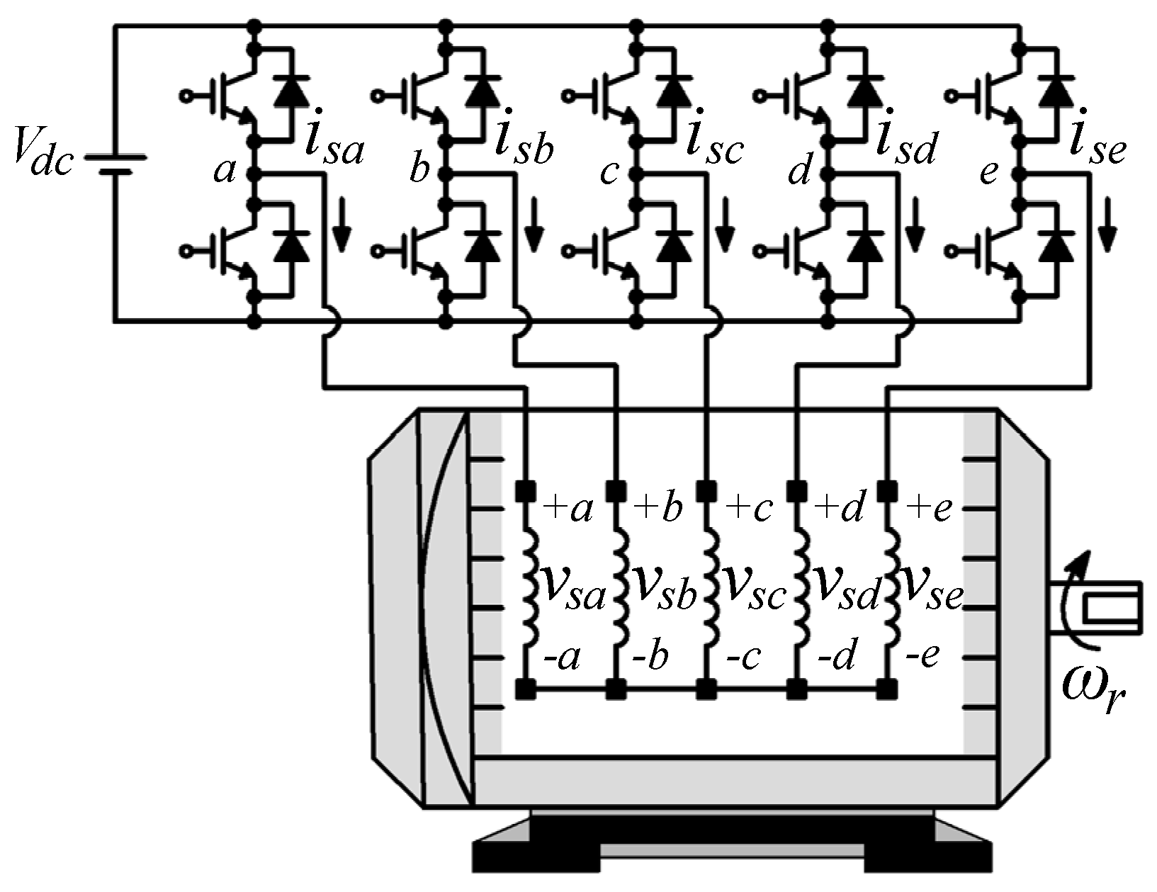
2. Background: Five-Phase Induction Machines and PSO Algorithm

This section is divided into two parts. First, an introduction of the five-phase induction machine used in the paper is presented. Second, the PSO algorithm used and its configuration parameters are described in details.

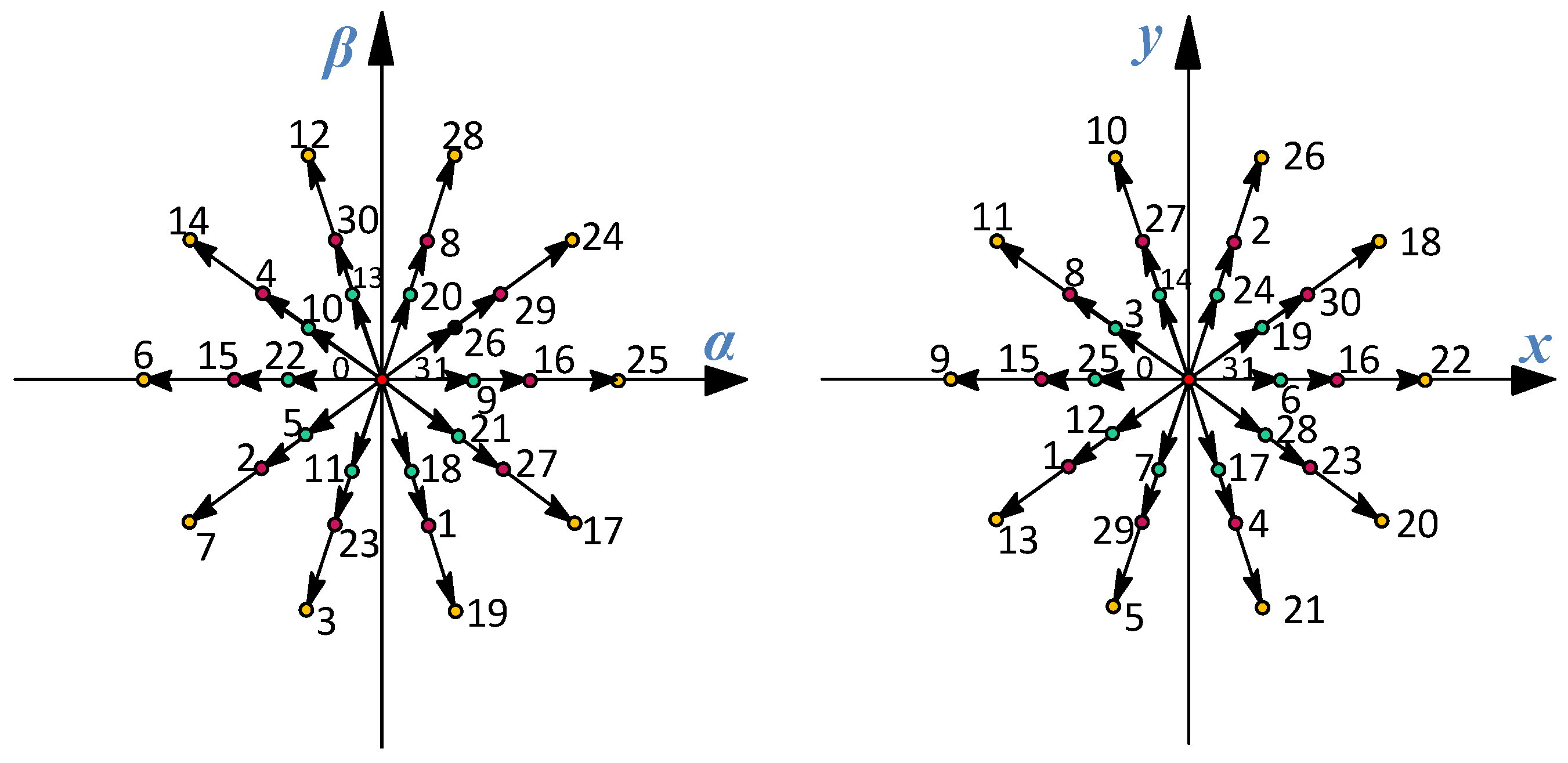
2.1. Five-Phase Induction Machines

The case under study is a symmetrical five-phase induction machine, where the stator windings are equally displaced (ϑ = 2π/5) and sinusoidally distributed along the stator. The multiphase drive is power-supplied using a two-level VSI, as can be observed in Figure 1.
The model of the system is more complex than the one obtained for a three-phase case due to the higher number of phases. However, the general theory of electrical machines is also applied to obtain the model of the system and the following assumptions are taken into account to obtain a set of continuous-time phase voltage equilibrium equations: machine windings are identical and equally distributed around the stator, magnetic field saturation and eddy currents are not considered, non-linearity in relation with temperature or frequency changes are not considered, and the machine air gap is assumed to be uniform and of constant density without any variation due to rotor eccentricities or machine slots. These equations can be simplified to avoid the dependence of the rotor position of certain parameter matrices using the Clarke transformation, which is used by the vector space decomposition theory to determine two orthogonal planes completely decoupled from each other (called α-β and x-y), plus an axis that contains the homopolar component (z-component). The obtained equations are detailed in (1)–(7), where the electrical parameters to be estimated are shown (the stator and rotor resistances, Rs and Rr, respectively, the mutual inductance represented by Lm, and the stator and rotor leakage inductances, Lls and Llr, respectively). It is interesting to mention that the fundamental supply component plus harmonics of the order 10n ± 1 (n = 0,1,2,3,...) are within the α–β subspace, which is the torque-producing plane. The rest of harmonic components are into the non-torque producing planes, including the x–y subspace, where supply harmonics of the order 10n ± 3 (n = 0,1,2,3,...) are considered, and the z-axis that contains harmonic components of the order 5n, with n = 1,2,3,... and only exists if the neutral point is not isolated. This is not our case because isolated neutral point is assumed and (7) is no longer required because isz = 0. Therefore, 32 (25) switching states and 30 active, and 2 zero voltage vectors can be generated in the α-β and x-y subspaces. Figure 2 identifies all available voltage vectors that can be applied to the multiphase machine, identified by using the decimal number corresponding to the binary code of the switching state Sa, Sb, Sc, Sd, Se, being Sa and Se the most and least significant bits, respectively. The modelling of the machine is finally complemented with a differential equation that describes the rotor movement depending on the electrical and load torques. Since this study focuses on the estimation of the electrical parameters of the machine, the movement equation is omitted here for simplicity (more details on the modelling of system can be found in [1,2,3,4]):
v s α = ( R s + L s d d t ) i s α + L m d i r α d t
v s β = ( R s + L s d d t ) i s β + L m d i r β d t
0 = ( R r + L r d d t ) i r α + L m d i s α d t + ω r L r i r β + ω r L m i s β
0 = ( R r + L r d d t ) i r β + L m d i s β d t ω r L r i r α ω r L m i s α
v s x = ( R s + L l s d d t ) i s x
v s y = ( R s + L l s d d t ) i s y
v s z = ( R s + L l s d d t ) i s z

2.2. PSO Algorithm

PSO is a meta-heuristic population-based technique. It is inspired by the social behavior of bird flocking and fish schooling; therefore, it is based on the swarm intelligence concept [17]. PSO refers to artificial intelligence systems where the collective behavior of unsophisticated agents that interact locally with their environment creates coherent global functional patterns [12,15]. In general, PSO algorithm uses a population of particles that fly throughout the problem hyperspace [18]. All the particles have fitness values that are evaluated by the fitness function to be optimized and have velocities vectors, which determine the movement of the particles in the search space. These velocities are stochastically adjusted throughout the execution of the algorithm according to the historical best position for the particle itself and the neighborhood (other neighbor particles) [12,15]. Therefore, the particles or candidate solutions fly throughout the problem search space attracted by the positions of the best particles found during the execution of the algorithm. PSO-based methods have been used in a wide range of engineering areas to solve complex continuous optimization problems, such as product design and manufacturing [19], automotive industry [20], structural design [21], and computer networks [22], among others [23,24].
Mathematically, the PSO algorithm is formulated as follows. First, a set of P particles (population) is randomly initialized. Note that the position of each particle is a possible solution for the estimation algorithm and it is represented by a d-dimensional vector in the problem space x i = ( x i 1 , x i 2 , ,   x ) , being i = 1 , 2 ,   ,   P and s . Thus, each particle is randomly placed in the d-dimensional space as a candidate solution and its performance is evaluated using a predefined fitness function. The velocity of the ith particle v i = v i 1 , v i 2 , ,   v i d , v ϵ , is defined as the change of its position. Depending on the number of objectives considered by the fitness function, the PSO algorithms can be classified as single and multi-objective algorithms [25].
The information available for each particle is based on its own experience and the knowledge of the performance of other particles in its neighborhood. Therefore, each particle adjusts its trajectory based on its own previous best local position and the previous best global position attained by any particle of the swarm, namely pid and pgd. The velocities and positions of particles are updated using Equations (8) and (9), respectively:
v i d ( t + 1 ) = w v i d ( t ) + c 1 r a n d 1 ( p i d x i d ( t ) ) + c 2 r a n d 2 ( p g d x i d ( t ) )
x i d ( t + 1 ) = x i d ( t ) + v i d ( t )
where t is the iteration counter, w is the inertia weigh, c1 and c2 are the acceleration coefficients, and rand1 and rand2 are two random numbers uniformly distributed in the interval [0, 1]. The inertia weight controls the impact of previous velocities on the current velocity and it is used to control the convergence of the PSO [12]. To reduce this weight over the iterations allowing the algorithm to exploit some specific areas, w is updated according to the following equation:
w = w m a x w m a x w m i n i t e r max i t e r
where wmax and wmin are the maximum and minimum values that the inertia weight can take, iter the current iteration of the algorithm and itermax the maximum number of iterations. The acceleration coefficients c1 and c2 control how far a particle moves in a single iteration. The velocity update in Equation (8) has three major components. The first one is the inertia, which models the tendency of the particle to continue in the same direction that it has been travelling. The second component is usually referred as memory and it is the linear attraction towards the best position ever found by the given particle pid scaled by a random weight c 1 r a n d 1 . The last component, usually referred as cooperation or social knowledge, is the linear attraction towards the best position found by any particle pgd, scaled by another random weight c 2 r a n d 2 .
Algorithm 1
Objective function f ( x ) ,   x i = ( x i 1 , x i 2 , ,   x )
Initialize locations x i and velocity v i , i = 1 , 2 ,   ,   P
Find p g d from min { f ( x 1 ) ,   , f ( x P ) } at (t = 0)
While (criterion)
  For loop over all P particles and all d dimensions
  Generate new velocity v i d ( t + 1 ) using (8)
  Calculate new locations x i d ( t + 1 ) using (9)
  Evaluate objective function at new locations x i d ( t + 1 )
  Find p i d for each particle x i d
  End for
   Find the current p g d
   Update t = t + 1
End while
Output the final results x i d and p g d
with pid the PSO algorithm tries to force exploitation around local optimums, while with pgd the algorithm explores new areas of the search space. Both features are the main tools for the PSO algorithm to achieve satisfactory results in complex optimization problems like the one presented in this work. Algorithm 1 represents the original implementation of the PSO algorithm used in this work. Furthermore, in this work, each individual will represent the set of electrical parameters to be estimated using the PSO algorithm, whose result will be proven to converge to an optimal solution.

3. Suggested Estimation Procedure

The proposal presented in this work utilizes both the standstill technique and the PSO procedure that have been particularized to the system under study, which is a symmetrical five-phase induction machine with distributed windings fed by a two-level VSI. In order to have a better understanding of the estimation procedure, this section will detail the standstill scheme, where an insight into how the electrical parameters are estimated is provided. Then, the application of the search engine based on the PSO method to obtain the final estimation is described.

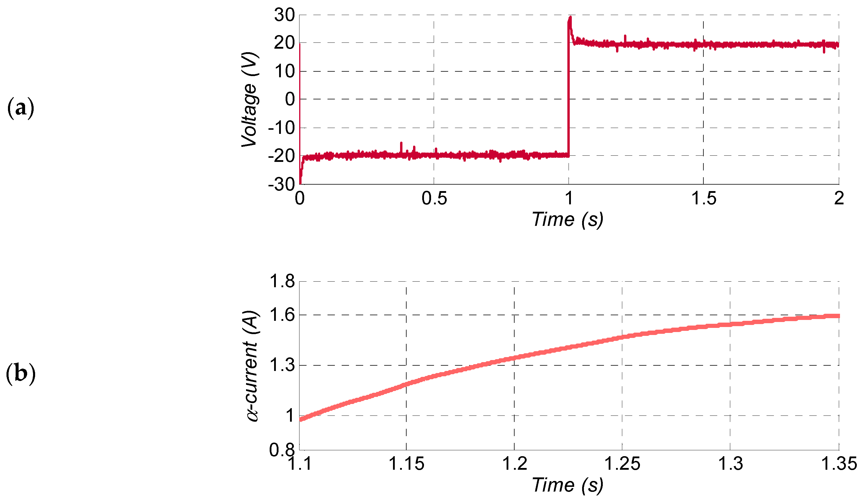
3.1. Standstill Procedure in Five-Phase Induction Drives

The basis of standstill identification schemes is that the machine model can be simplified when the rotor speed is zero (ωr = 0). This can be obtained with an appropriate stator winding arrangement that avoids the generation of electrical torque. Several stator winding arrangements can be chosen, generating different stator current components. Table 1 summarizes two winding arrangements proposed in [9] for the identification of the electrical parameters in the α-β (first row) and x-y (second row) subspaces. The first one maximizes the α–axis component with respect to the x-axis component (winding connection 1), while the remaining components are zero. This arrangement allows two identification processes in the α-β subspace for the estimation of the rotor parameters (Rr, Llr) and the magnetizing inductance (Lm). The second one maximizes the x-axis component with respect to the α-axis component (winding connection 2), generating null components in the rest. Then, this second arrangement allows one identification process in the x-y subspace to estimate the stator resistance (Rs) and stator leakage inductance (Lls) parameters. The resulting discrete dynamics models, which will be used in the identification process, are obtained as follows.
The first identification model focuses on the α-β plane and it is shown in the upper row of Table 1. Then, a winding arrangement is chosen to minimize stator voltage in the x-y subspace and reduce any interference between orthogonal frames. However, notice that the obtained stator voltage is not null in the x-y plane, so certain disturbance in the identification process is generated. The stator and rotor current responses in the α–axis can be described by the following equations:
V s α ( s ) = ( R s + s L s ) I s α ( s ) + s L m I r α ( s ) 0 = ( R r + s L r ) I r α ( s ) + s L m I s α ( s )
The transfer function that models the current response in the α–β subspace is as follows:
V s α ( s ) = ( R s + s σ L s ) I s α ( s ) + s K T 1 + s τ r I s α ( s )
where KT = Lm2/Lr, τr = Lr/Rr and σLs = LsKT.
The continuous-time transfer function that describes the α–axis stator current response can be simplified using the term Vsr(s) detailed in (13), as it is shown in (14), and discretized using a zero-order holder as it is stated in (15):
V s r ( s ) = V s α ( s ) ( R s + s σ L s ) I s α ( s )
I s α ( s ) V s r ( s ) = ( 1 + s τ r ) K T s
I s α ( z ) V s r ( z ) = Z { 1 e s T s s · 1 + s τ r K T s } = τ r + ( T s + τ r ) z 1 K T ( 1 z 1 )
where Ts is the sampling period.
This model, also called “full-order transfer function model in the α-β subspace”, provides information of current response in the α-β plane. In essence, the same model has been so far used in the identification process of three-phase machines using standstill techniques whose parameters are identified using this transfer function.
The model in the x-y subspace is now studied. The continuous-time transfer function that describes the x-axis current response is obtained after creating a stator voltage using the winding arrangement shown in the second row in Table 1:
I s x ( s ) V s x ( s ) = 1 ( R s + s L l s ) = 1 R s ( 1 + s τ l s )
where τls = Lls/Rs.
This model in the x-y subspace can be referred as the “stator leakage inductance model” because it contributes to the estimation allowing the identification of the Lls parameter. The input voltage in the x–axis depends on Vdc, as it is detailed in Table 1 (fourth column). Notice that the obtained stator voltage is not null in α-β plane. Therefore, certain disturbance to the identification process is generated as in the previous case. The model of the current response is then discretized using a zero-order hold as follows:
I s x ( z ) V s x ( z ) = Z { 1 e s T s s · 1 R s ( 1 + s τ l s ) } = ( 1 e T s / τ l s ) z 1 R s ( 1 e T s / τ l s z 1 )
The stator leakage inductance model provides additional information, compared with the three-phase case, about the identification of Rs and Lls parameters, and will be used for this purpose.

3.2. Search Engine for the Estimation Process Using PSO

The main idea of using the PSO algorithm in this complex application is to converge towards a good solution of the estimated electrical parameters of a five-phase induction machine. Each particle is composed of a set of electrical parameters like an unknown vector x = [Rs Rr Lm Lls Llr] to be accurately estimated. The fitness function used to evaluate the quality of every particle in the population is the mean squared error (MSE) between the outputs given by the real system (the multiphase induction machine, y α and y x in Equation (18) and the outputs given by a modelled system (using Matlab and named y ^ α and y ^ x ). Both systems (the real machine and the Matlab-based model) are governed using stator voltages in the standstill configuration to generate first a response in the α-β subspace and then in the x-y plane. The full-order model is avoided to guarantee that the estimation of the α-β parameters (involved in the main control magnitudes of the electrical drive such as the electrical torque and the stator flux production) is made without having any interference of the x-y plane, which is related to the electrical losses in a machine with distributed winding. For this reason, the same weights have been considered for both subspaces α-β and x-y. Consequently, the proposed fitness function g for this study is defined as follows:
g = M S E x 2 + M S E α 2
M S E α 2 = 1 N α k = 1 N α y α ( k ) y ^ α ( k ) 2
M S E x 2 = 1 N x k = 1 N x y x ( k ) y ^ x ( k ) 2
where the MSEα and MSEx values are the mean squared errors computed for the response in the α- and x-axis, respectively, and Nα and Nx regulate the desired accuracy in the estimation of the α-β and x-y parameters (in this case, the same accuracy has been selected).
The complexity of the estimation procedure comes from adjusting simultaneously the two regression models of α-β and x-y planes based on the response of the multiphase machine in standstill arrangements to known input signals. On the one hand, the regression model of α-β plane that allows the estimation of Rr, Llr and Lm parameters. On the other hand, the x-y plane that enables the estimation of Rs and Lls. Notice that the five electrical parameters have continuous values ranging from the intervals included in Table 3 (see Section 4.1 for more details). Therefore, the complexity of the optimization problem consists in finding the most optimal values that reduce the error among the simulated response of electrical machine model with the electrical parameters as inputs and the real response obtained from experiments.

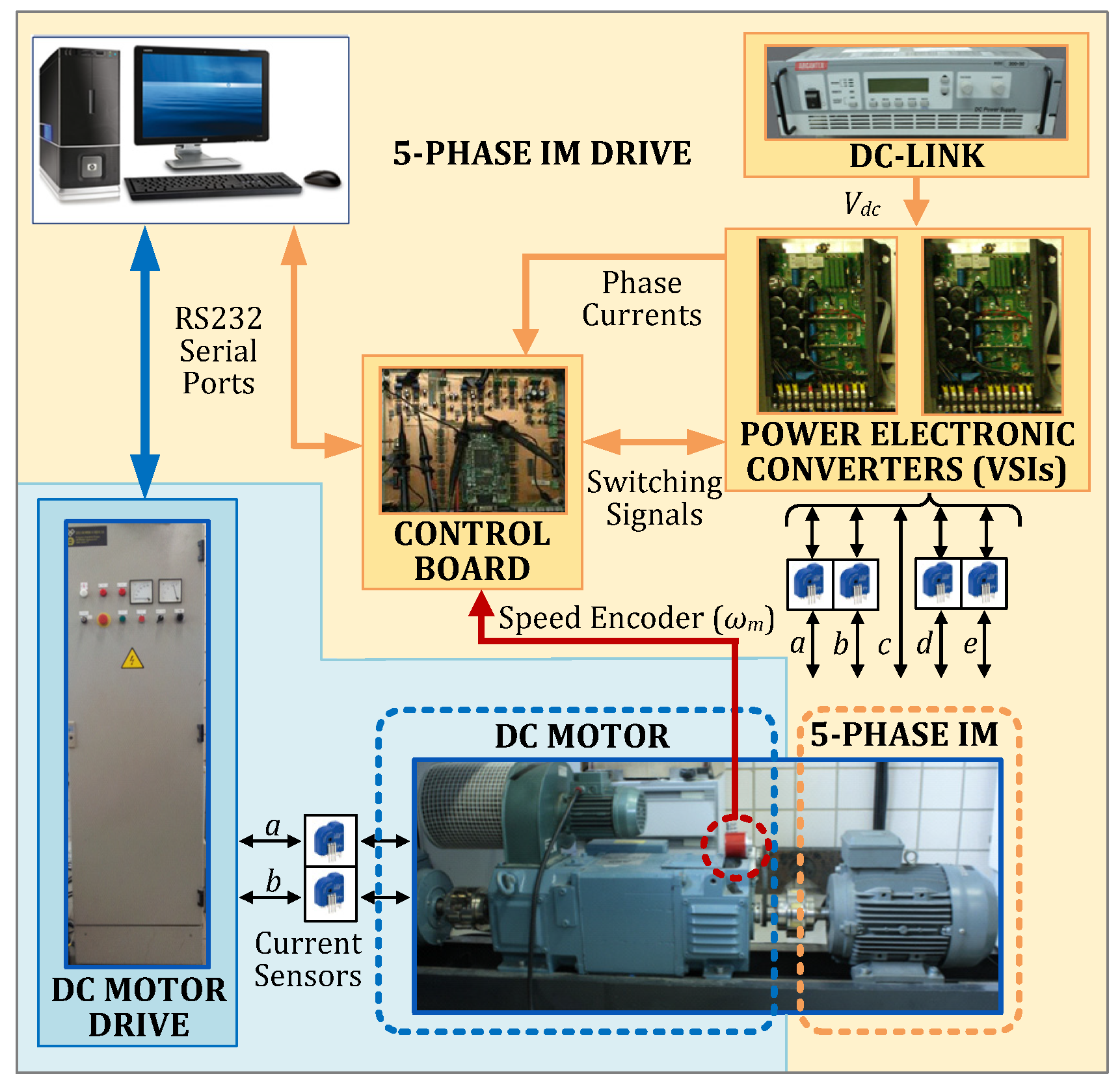
4. Experimental Assessment

The performance of the proposal is analyzed using an experimental test bench based on a symmetrical five-phase induction machine with distributed windings. The multiphase machine was built from a commercial three-phase induction machine that has been rewound and reassembled. Then, the proposed estimation technique is applied to obtain the unidentified vector x = [Rs Rr Lm Lls Llr] that represents the electrical parameters of the multi-phase machine. Figure 3 shows an scheme of the experimental test bench, where pictures of electronic equipment are included. The VSI-based multiphase power converter is built from two commercial three-phase modules from Semikron (SKS21F) that are linked to a unique DC of up to 300 V. The controller is based on a well-known digital signal processor from Texas Instruments (12500 TI Boulevard, Dallas, TX, USA) and Technosoft (Avenue des Alpes 20, 2000 Neuchâtel, Switzerland), the TMS320LF28335 and the MSK28335 board, respectively. Sensing some electrical variables (stator currents and voltages) is a major requirement in the estimation strategy, which it is done using two different sensors from LEM (Chemin des Aulx 8, P.O. Box 35, 1228 Plan-les-Ouates, Switzerland), the LA-55P and LV-25P devices. It is important to highlight that the voltage electrical signals obtained from the sensors are filtered using analog low-pass filters with a cut-off frequency of 1.5 kHz. It is also interesting to remark that the windings of the multiphase machine must be rearranged to avoid torque generation and to assure the standstill behavior. This is done following the connection scheme shown in the first row of Table 1.

4.1. Identification of the Electrical Parameters of the System

Two different stator voltages are applied using the proposed standstill tests in α-β and x-y subspaces and the current responses of the system are recorded. The winding connection shown in the first row of Table 1 is initially used and a step voltage from –20 to 20 V is applied to the machine, Figure 4a, to obtain the current response in the α–axis shown in Figure 4b. This voltage excites the electromagnetic circuit and rotor time constants at standstill in the α-axis, as it is detailed in Equation (15). The winding connection shown in the second row of Table 1 is then used and a three-level signal (–60, 0 and 60 V) with a fundamental frequency of 25 Hz is applied to the stator, see Figure 4c. This stator voltage excites the stator electromagnetic circuit detailed in Equation (17), producing the stator current in the x–axis shown in Figure 4d. The obtained stator current responses y are then compared with the modelled responses ŷ, evaluated with Equations (15) and (17) in order to compute the fitness function g (18) of each individual in the PSO algorithm.
Table 2 contains the configuration parameters used in the PSO algorithm, which is designed to stop under two circumstances. The PSO algorithm has been run for 30 independent trials. Each trial is stopped under the following events: first, if 400 iterations are reached, or second, if the best global position does not change during 40 iterations or the change is lower than the lowest error gradient tolerance (errgrad). Notice that realistic variation intervals for the electrical parameters of the machine (summarized in Table 3) must be supplied to the PSO algorithm to ensure a proper solution. Consequently, previous knowledge of the real system is required to apply the proposed estimation algorithm.
To select the suitable values of the adjusting parameters of the PSO algorithm, massive simulations have been conducted varying the parameters, such as ps, c1, c2, Vmax, and Wmax, according to the intervals included in Table 2. A grid search has been conducted by dividing each interval of each configuration parameter into four. Each point of the grid has been evaluated for 30 independent trials. Therefore, about 8000 simulations have been conducted. In general, the results are satisfactory for all the cases considered since important differences in the obtained results are not observed. According to the results in Table 4, the most suitable adjusting parameters for the PSO implementation are: ps = 75, c1 = c2 = 1, Vmax = 1, and Wmax = 0.9. Table 4 details the estimated parameters for the best run, obtained with a computed error of 0.1701. The identification method based on gradient-based optimization algorithms and proposed in [9] was also applied to compare with these results, giving an estimated error about 2.58% higher than the obtained using the PSO technique. Then, an improvement in the estimation procedure is obtained, which proves the interest and applicability of the proposal. Notice that the accuracy of the electrical parameters has strong impact on the closed-loop performance of the system, being an important trend in control theory for electrical drives.
Moreover, Table 5 includes statistical results with respect to the number of particles used in the PSO algorithm. Notice that important differences are not noticeable when the number of particles is higher than 75. Therefore, it has been chosen 75 as appropriated number of particles for the target optimization problem.

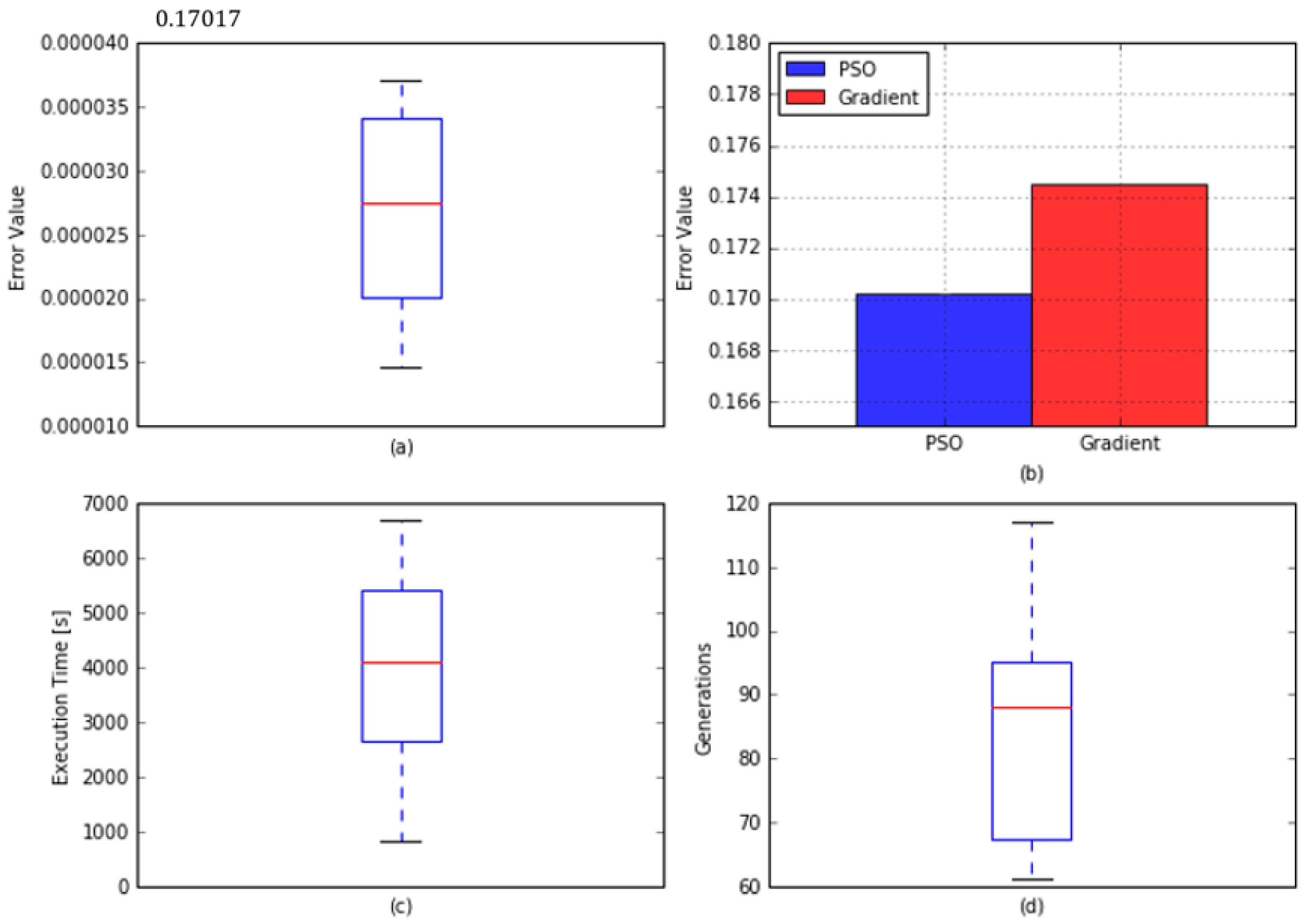
4.2. Stadistical Analysis and Comparison with a Grandient-Based Approach

Figure 5 depicts several performance metrics of the proposed approach. Figure 5a shows the boxplot for the error distribution obtained in the conducted trials, where the obtained distribution data results are shown in a standardized way. Boxplots are normally used to show the dispersion of the simulation results. They represent the median and the 25% and 75% of the simulation results. Therefore, boxplots are ideal tool for statistical analysis. It may be observed that the deviation in the distribution of the results is very low (2.4569 × 10⁻⁶) in comparison with the evaluated mean. Figure 5b compares the obtained average results using the proposed PSO-based technique and the gradient-based approach presented in [8,9]. It may be concluded that the proposed estimation technique reduces the error value considerably. Another important issue to highlight is that the 95% confident interval for the obtained results using the PSO-based approach is 8.1786 × 10⁻⁶. Therefore, the proposed PSO-based approach clearly outperforms the gradient-based technique for all the conducted trials. Finally, Figure 5c,d depict the performance of the proposed estimation technique in terms of execution time and number of generations required for convergence. Notice that the execution time is not critical in this optimization problem since it is obviously and offline procedure. Nevertheless, the proposed approach provides results in 4000 s (approximately 1 h) on average. These results were obtained using a Toshiba Satellite L755 Intel® Core™ i7 2670QM, 4 G RAM. Consequently, the execution time can be considerably reduced using a modern workstation. Regarding the number of generations required for the convergence, it may be observed (see Figure 5d) that the convergence is usually reached in less than 100 generations. The considered stopping criterion in the PSO configuration (until 400 generations can be run if necessary) is then a suitable configuration set.

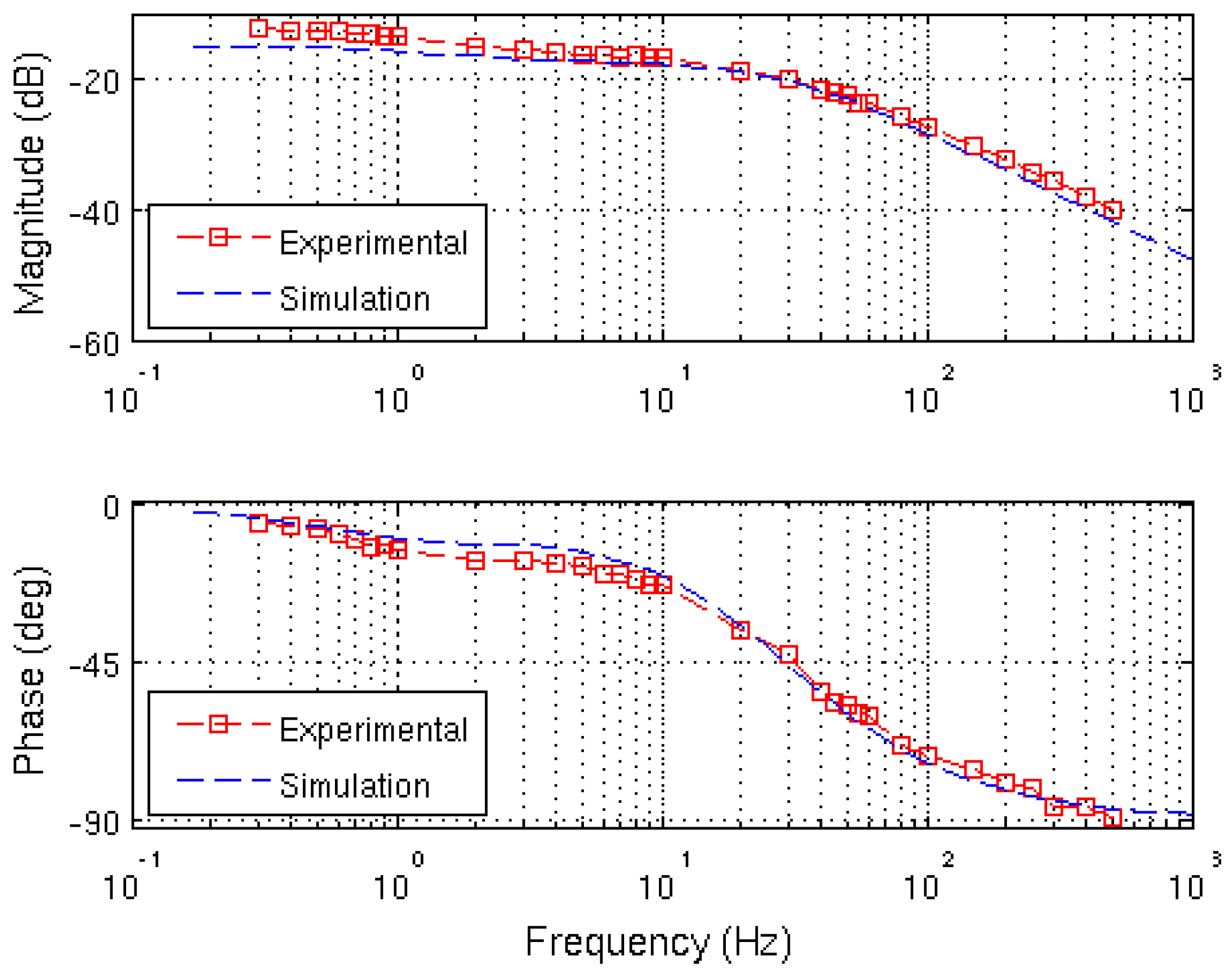
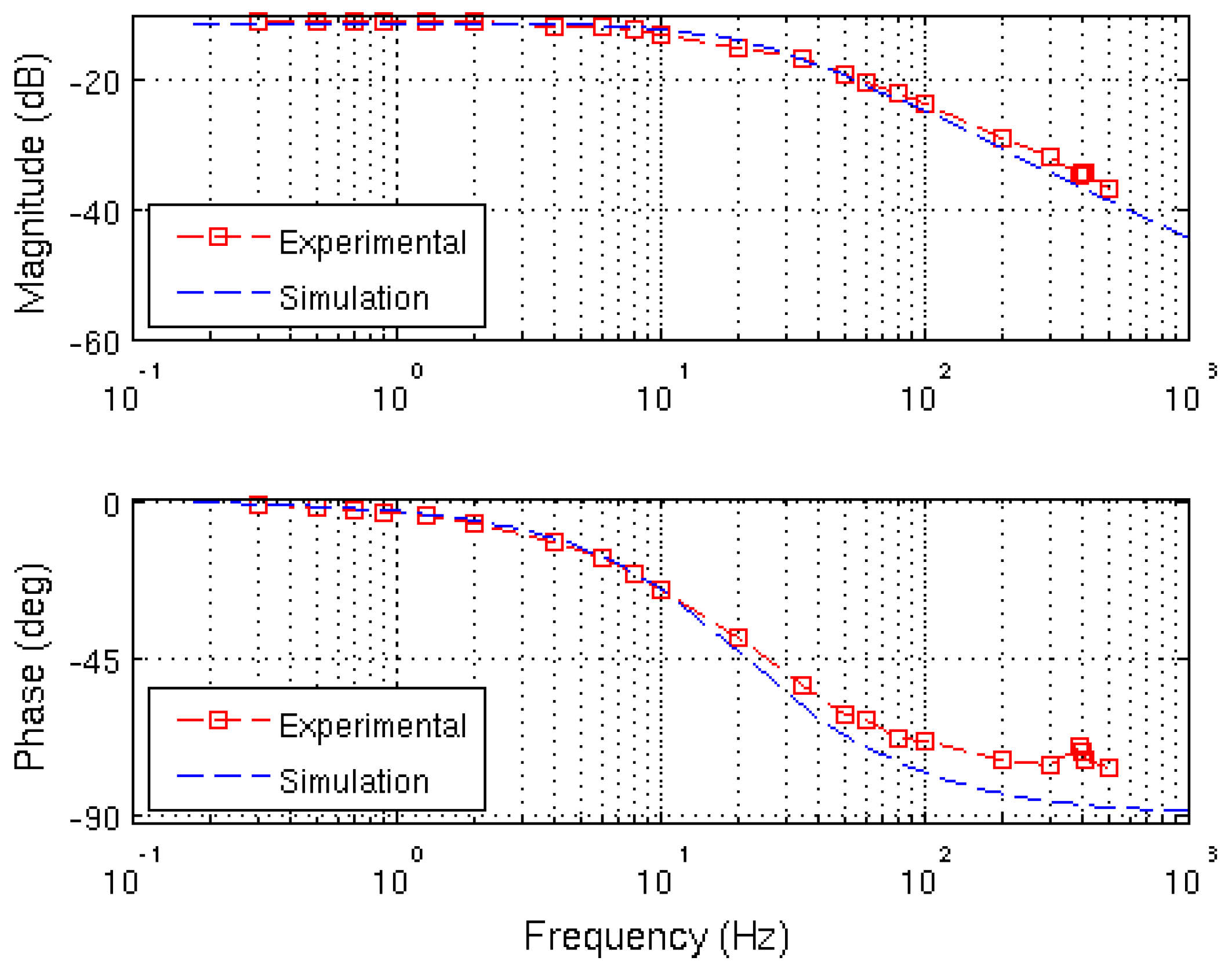
4.3. Experimental Validation of the Estimated Parameters

To analyze the validity of the results obtained, a graph of the estimated transfer functions is plotted with a log-frequency axis in order to compare the theoretical and experimental frequency responses of the system (Bode plot). The mathematical representation of the system shown in previous equations is compared with the real behavior using the proposed winding arrangements and the estimated parameters. Figure 6 and Figure 7 show the obtained results. Figure 6 depicts theoretical and experimental Bode plots in the α-β plane in blue and red ink, respectively. A good agreement is observed in Figure 6. Moreover, Figure 7 shows theoretical and experimental Bode plots in the x-y plane. Again, theoretical and experimental behaviors are quite similar. Notice that some differences exist. These differences can be justified due to the inaccuracy of the initial modelling assumptions, the error in the measurement process and the relationship with the frequency of the electrical parameters of the machine. Such differences produce that the experimental transfer function varies from the theoretical one as the frequency increases.

5. Conclusions

This paper describes a novel off–line procedure for the estimation of the electrical parameters of a multi-variable electro-mechanical system. Unlike recently proposed gradient-based methods, this proposal utilizes the PSO technique as a proof-of-concept of the application of meta-heuristic optimization algorithms in the estimation of electrical parameters based on standstill methods. The method has been tested in a real system using a multiphase test rig with a five-phase induction machine. In addition, it has been compared with sinusoidal and time domain gradient-based estimation techniques. A reduction higher than 2.58% is obtained in the best solution error. Notice that this result is relevant for the development of high performance modern controllers where the knowledge of the electrical parameters of the multiphase drive is crucial, such as in predictive control algorithms. Furthermore, this work paves the way for future application of other variants of population-based techniques, such as the genetic algorithm (GA) and firefly algorithm (FA), and other recent trajectory-based algorithm, such as simulated annealing (SA), tabu search (TB) and harmony search (HS), among others, for the optimization problem presented in the estimation of electrical parameters of multiphase machines based on standstill tests. It is interesting to note that although the proposal has been tested for a particular multiphase drive (five-phase machine), it can be extended for identification purposes in different electrical drives. There are no restrictions in the application of our proposal in different multiphase electrical machines, although the propose windings’ arrangement (Table 1) is no longer valid and must be adapted to the standstill requirements of the new machine.

Author Contributions

Conceptualization, F.B. and S.L.T.; Methodology, F.B., J.R. and D.G.-R.; Software, D.G.-R. and J.R.; Validation, D.G.-R., J.R. and I.G.-P.; Formal Analysis, D.G.-R., J.R. and I.G.-P.; Investigation, D.G.-R. and J.R.; Resources, F.B. and M.J.D.; Data Curation, D.G.-R. and J.R.; Writing-Original Draft Preparation, F.B. and D.G.-R.; Writing-Review & Editing, F.B., D.G.-R., I.G.-P., M.J.D.; Visualization, F.B.; Supervision, F.B.; Project Administration, F.B.; Funding Acquisition, F.B.

Funding

This research received no external funding.

Acknowledgments

The authors would like to thanks the University of Seville and the Spanish national R + D + I program (under references DPI2013-44278-R and DPI2016-76144-R) for the equipment used for experiments.

Conflicts of Interest

The authors declare no conflict of interest.

References

  1. Barrero, F.; Duran, M.J. Recent Advances in the Design, Modeling and Control of Multiphase Machines—Part 1. IEEE Trans. Ind. Electron. 2016, 63, 449–458. [Google Scholar] [CrossRef]
  2. Duran, M.J.; Barrero, F. Recent Advances in the Design, Modeling and Control of Multiphase Machines—Part 2. IEEE Trans. Ind. Electron. 2016, 63, 459–468. [Google Scholar] [CrossRef]
  3. Duran, M.J.; Riveros, J.; Barrero, F.; Guzmán, H.; Prieto, J. Reduction of common-mode voltage in five-phase induction motor drives using predictive control techniques. IEEE Trans. Ind. Appl. 2012, 48, 2059–2067. [Google Scholar] [CrossRef]
  4. Riveros, J.A.; Barrero, F.; Levi, E.; Durán, M.J.; Toral, S.; Jones, M. Variable-speed five-phase induction motor drive based on predictive torque control. IEEE Trans. Ind. Electron. 2013, 60, 2957–2968. [Google Scholar] [CrossRef]
  5. Carraro, M.; Zigliotto, M. Automatic Parameter Identification of Inverter-Fed Induction Motors at Standstill. IEEE Trans. Ind. Electron. 2014, 61, 4605–4613. [Google Scholar] [CrossRef]
  6. Lee, S.H.; Yoo, A.; Lee, H.-J.; Yoon, Y.-D.; Han, B.-M. Identification of Induction Motor Parameters at Standstill Based on Integral Calculation. IEEE Trans. Ind. Appl. 2017, 53, 2130–2139. [Google Scholar] [CrossRef]
  7. He, Y.; Wang, Y.; Feng, Y.; Wang, Z. Parameter Identification of an Induction Machine at Standstill Using the Vector Constructing Method. IEEE Trans. Power Electron. 2012, 27, 905–915. [Google Scholar] [CrossRef]
  8. Yepes, A.G.; Riveros, J.A.; Doval-Gandoy, J.; Barrero, F.; López, O.; Bogado, B.; Jones, M.; Levi, E. Parameter identification of multiphase induction machine with distributed windings—Part 1: Sinusoidal excitation methods. IEEE Trans. Energy Convers. 2012, 27, 1056–1066. [Google Scholar] [CrossRef]
  9. Riveros, J.A.; Yepes, A.G.; Barrero, F.; Doval-Gandoy, J.; Bogado, B.; Lopez, O.; Jones, M.; Levi, E. Parameter identification of multiphase induction machine with distributed windings—Part 2: Time domain techniques. IEEE Trans. Energy Convers. 2012, 27, 1067–1077. [Google Scholar] [CrossRef]
  10. Sakthivel, V.P.; Bhuvaneswari, R.; Subramanian, S. Artificial immune system for parameter estimation of induction motor. Expert Syst. Appl. 2010, 37, 6109–6115. [Google Scholar] [CrossRef]
  11. Bettayeb, M.; Qidwai, U. A hybrid least squares-GA-based algorithm for harmonic estimation. IEEE Trans. Power Deliv. 2003, 12, 377–382. [Google Scholar] [CrossRef]
  12. Wang, D.; Tan, D.; Liu, L. Particle swarm optimization algorithm: An overview. Soft Comput. 2018, 22, 387–408. [Google Scholar] [CrossRef]
  13. Fernandez-Martinez, J.L.; Garcia-Gonzalo, E. Stochastic Stability Analysis of the Linear Continuous and Discrete PSO Models. IEEE Trans. Evol. Comput. 2011, 15, 405–423. [Google Scholar] [CrossRef]
  14. Del Valle, Y.; Venayagamoorthy, G.K.; Mohagheghi, S.; Harley, R.G.; Hernandez, J.C. Particle swarm optimization: Basic concepts, variants and applications in power systems. IEEE Trans. Evol. Comput. 2008, 12, 171–195. [Google Scholar] [CrossRef]
  15. Eslami, M.; Shareef, H.; Mohamed, A.; Khajehzadeh, M. An efficient particle swarm optimization technique with chaotic sequence for optimal tuning and placement of PSS in power systems. Int. J. Electr. Power Energy Syst. 2012, 43, 1467–1478. [Google Scholar] [CrossRef]
  16. Guzman, H.; Duran, M.J.; Barrero, F.; Zarri, L.; Bogado, B.; Prieto, I.G.; Arahal, M.R. Comparative Study of Predictive and Resonant Controllers in Fault-Tolerant Five-phase Induction Motor Drives. IEEE Trans. Ind. Electron. 2016, 63, 606–617. [Google Scholar] [CrossRef]
  17. Zhang, J.; Yang, S. A novel PSO algorithm based on an incremental-PID-controlled search strategy. Soft Comput. 2016, 20, 991–1005. [Google Scholar] [CrossRef]
  18. Rada-Vilela, J.; Johnston, M.; Zhang, M. Population statistics for particle swarm optimization: Single-evaluation methods in noisy optimization problems. Soft Comput. 2015, 19, 2691–2716. [Google Scholar] [CrossRef]
  19. Yıldız, A.R. A novel particle swarm optimization approach for product design and manufacturing. Int. J. Adv. Manuf. Technol. 2009, 40, 617–628. [Google Scholar] [CrossRef]
  20. Yıldız, A.R. A new hybrid particle swarm optimization approach for structural design optimization in automotive industry. J. Automob. Eng. 2012, 226, 1340–1351. [Google Scholar] [CrossRef]
  21. Yıldız, A.R. Comparison of evolutionary based optimization algorithms for structural design optimization. Eng. Appl. Artif. Intell. 2013, 26, 327–333. [Google Scholar] [CrossRef]
  22. Sheikhan, M.; Mohammadi, N. Time series prediction using PSO-optimized neural network and hybrid feature selection algorithm for IEEE load data. Neural Comput. Appl. 2013, 23, 1195. [Google Scholar] [CrossRef]
  23. Krama, A.; Zellouma, L.; Rabhi, B.; Refaat, S.; Bouzidi, M. Real-Time Implementation of High Performance Control Scheme for Grid-Tied PV System for Power Quality Enhancement Based on MPPC-SVM Optimized by PSO Algorithm. Energies 2018, 11, 3516. [Google Scholar] [CrossRef]
  24. Yun, P.; Ren, Y.; Xue, Y. Energy-Storage Optimization Strategy for Reducing Wind Power Fluctuation via Markov Prediction and PSO Method. Energies 2018, 11, 3393. [Google Scholar] [CrossRef]
  25. Yildiz, A.R.; Solanki, K.N. Multi-objective optimization of vehicle crashworthiness using a new particle swarm based approach. Int. J. Adv. Manuf. Technol. 2012, 59, 367–376. [Google Scholar] [CrossRef]
Figure 1. General scheme of the system under study.
Energies 12 00314 g001
Figure 2. Generated voltage vectors in the α-β and x-y planes. Note that the same switching state produces two different vectors in every plane.
Energies 12 00314 g002
Figure 3. Scheme of the experimental test bench.
Energies 12 00314 g003
Figure 4. Applied stator voltage in the winding connection 1 (a) and the measured i (b). Applied stator voltage in the winding connection 2 (c) and the measured isx (d).
Energies 12 00314 g004aEnergies 12 00314 g004b
Figure 5. Statistical analysis of the results showing (a) the obtained estimation error, (b) a performance comparison between the PSO-based and gradient-based approaches, (c) the execution time of the proposed estimation procedure, and (d) the number of generation required for the convergence of the algorithm.
Energies 12 00314 g005
Figure 6. Simulation (blue dashed plot) and experimental (red squares plot) Bode frequency responses in the α-β subspace.
Energies 12 00314 g006
Figure 7. Simulation (blue dashed plot) and experimental (red squares plot) Bode frequency responses in the x–y subspace.
Energies 12 00314 g007
Table 1. Two available windings’ arrangements in a five-phase induction machine for the single-phase standstill estimation procedure.
Winding ConnectionsVoltage VectorsDecoupled Voltage Components
Energies 12 00314 i001 Energies 12 00314 i002 v s α = 1.1708 V d c
v s x = 0.1708 V d c
v s z = 0
v s β = v s y = 0
Energies 12 00314 i003 Energies 12 00314 i004 v s α = 0.1708 V d c
v s x = 1.1708 V d c
v s z = 0
v s β = v s y = 0
Table 2. Configuration parameters of the PSO algorithm.
PSO ParameterValue
Number of trials30
Number of particles (ps)[25, 125]
Acceleration coefficients (c1 and c2)c1= c2 = [0.1, 2]
Inertia weights (wmax and wmin)wmax = [0.5, 1.4] and wmin = 0.3
Maximum particle velocity (vmax)vmax = [1, 3]
Lowest error gradient tolerance (errgrad)errgrad = 1·× 10-6
Maximum number of generation without error change (errgraditer)errgraditer = 40
Maximum number of iterations (itermax)itermax = 400
Table 3. Parameter ranges for the PSO variables.
Machine ParameterInterval
Rs (Ω)[10, 25]
Rr (Ω)[1, 10]
Lm (H)[0.5, 0.7]
Lls (H)[0.010, 0.160]
Llr (H)[0.010, 0.060]
Table 4. Obtained parameters using the PSO algorithm.
Machine ParameterValue
Rs (Ω)19.4462
Rr (Ω)6.7659
Lm (H)0.6565
Lls (H)0.1007
Llr (H)0.0386
Table 5. Estimation error versus number of particles ps.
PsMax.MeanStd.
250.33400.34508.4569 × 10−6
500.18790.19283.4569 × 10−6
750.17010.17452.4569 × 10−6
1000.17220.20382.2269 × 10−6
1250.17250.17552.1100 × 10−6

