Characteristic Analysis of DFIG Wind Turbine under Blade Mass Imbalance Fault in View of Wind Speed Spatiotemporal Distribution


Department of Mechanical Engineering, North China Electric Power University, Baoding 071003, China
*
Author to whom correspondence should be addressed.
Energies 2019, 12(16), 3178; https://doi.org/10.3390/en12163178
Submission received: 8 July 2019
/
Revised: 13 August 2019
/
Accepted: 14 August 2019
/
Published: 19 August 2019
Abstract
:The blade mass imbalance fault is one of the common faults of the DFIG (Doubly-Fed Induction Generator) wind turbines (WTs). In this paper, considering the spatiotemporal distribution of natural wind speed and the influence of wind shear and tower shadow effect, the influence of blade mass imbalance faults on the electrical characteristics of DFIG WTs is analyzed. Firstly, the analytical expressions and variation characteristics of electromagnetic torque and electromagnetic power under blade mass imbalance are derived before and after consideration of the spatiotemporal distribution of wind speed. Then simulations on the MATLAB/Simulink platform were done to verify the theoretical analysis results. The theoretical analysis and simulation results show that, considering the spatiotemporal distribution of wind speed and the influence of wind shear and tower shadow effect, the blade mass imbalance fault will cause fluctuation at the frequency of 1P (P = the frequency of rotor rotation), 3P, and 6P on electromagnetic power. Fluctuation at 1P is caused by mass imbalance while fluctuation at 3P and 6P are caused by wind speed spatiotemporal distribution; the amplitude of fluctuation at 1P is proportional to the degree of the imbalance fault. Since the equivalent wind speed has been used in this paper instead of the average wind speed, the data is more suitable for the actual operation of the WT in the natural world and can be applied for fault diagnosis in field WT operation.
1. Introduction
The blade mass imbalance of WTs is a kind of fault that often occurs in the operation of WTs. WTs mostly operate in outdoor or offshore environments where the environment is relatively harsh, and sand or ice deposits may cause blade mass imbalance. In addition, fatigue stress will cause cracks in the blade, and the entry of dust, debris, rainwater, etc., into cracks, can cause blade mass imbalance, further aggravating the fatigue of the blade and other components. This will cause serious damage to the wind turbine generators (WTGs) if continued operation is allowed [1,2,3]. With the rapid global development of large-capacity WTs, the occurrence of blade mass imbalances will become frequent. Therefore, the early identification and diagnosis of blade mass imbalance is an important problem to be solved in the field of fault diagnosis for WTs [4,5]. Aiming for the identification and diagnosis of blade mass imbalance, the WT model was established in [6], and the finite element method was used to analyze the vibration characteristics of the WTGs caused by blade mass imbalance. Previous papers [7,8] collected the vibration signal of the WTGs on the simulation test-bed for spectrum analysis. The results show that the vibration of the WTGs in the horizontal direction will increase under the condition of mass imbalance. Previous studies have [9,10,11] analyzed the relationship between blade mass imbalance and generated power and have found that the blade mass imbalance fault will cause fluctuation in output torque of the wind rotor, which is then reflected in the electric power signal of WTGs through the transmission chain. One study [9] achieved the preliminary diagnosis of blade mass imbalance and blade aerodynamic asymmetry by analyzing the power spectral density of WT. Another study [10] believes that the periodic variation of unbalanced forces caused by the blade mass imbalance will directly cause fluctuations of output power, but the reasons are not analyzed in detail. In a separate study [12], the relationship between generator stator current and shaft rotational frequency was analyzed under the condition of blade mass imbalance in direct-drive permanent-magnet WTs. The stator current signal is used to analyze the change in characteristics of frequency to diagnose blade mass imbalance. In [13], the effects of blade mass imbalance and aerodynamic asymmetry on the stator current of the direct-drive permanent-magnet WTs were analyzed, and the stator current square signal obtained by fast Fourier transform (FFT) was used for spectral analysis. The blade mass imbalance and winding asymmetry are diagnosed using the frequency, variation, and amplitude characteristics of the stator current square signal. In [14], the characteristics and changes in the time-domain, spectrum curve of rotor speed, and electromagnetic power signal—under different degrees of unbalanced faults—were analyzed. The results showed that electromagnetic power signal contained the first-harmonic component and second-harmonic component of the motor rotation, and amplitude increased as the unbalanced mass increased. [15] was simulated in MATLAB/Simulink, and the output power of the DFIG WTs fluctuated when the blade mass imbalance was verified by the experiment. The frequency is the rotating frequency and its frequency of blade and doubling.
Through the analysis of existing research, most of the current research on WTs are based on the average wind speed at the hub center, without considering the spatiotemporal distribution of wind speed. However, due to the presence of wind shear and tower shadow effects, the wind captured by WTs in nature varies with time and space, and complex wind conditions can affect the output power of the WT. Scholars have discovered the phenomenon of periodic power fluctuation caused by wind shear and tower shadow effect for a long time. In [16], an analytical formulation of the generated aerodynamic torque of a three-bladed wind turbine, including the effects of wind shear and tower shadow, was presented. The model proves the existence of a 3P pulsation due to wind shear. In [17], a simulation system—supported by TurSim, AeroDyn, and FAST—was established, and the impact of wind shear, tower shadow effect, and yaw error on power generation quality were studied. In [18], the existence of the tower shadow effect and its influence on the output power was verified by analyzing the measured data of the wind farm. In [19], the effects of wind shear and tower shadow effects were studied via both power fluctuation and average output power. They concluded that both wind shear and tower response are sources of periodic power fluctuations and average power loss.
However, from current research, there has not been enough study of fault characteristics considering the spatiotemporal distribution of wind speed. Therefore, in the actual application of fault diagnosis, the diagnosis result may not match the ideal diagnosis result or may have a large diagnostic error, resulting in the failure of the diagnostic method. On the basis of considering the spatiotemporal distribution of practical natural wind speeds, this paper studies the electrical characteristics and the fault diagnosis of the DFIG WTs when there is blade mass imbalance, and finds the fault diagnosis basis to assist the early detection and diagnosis of the fault. This may help in the avoidance of major accidents and improves the operating efficiency of DFIG WTs.
2. DFIG WTs Model and Blade Mass Imbalance Model
2.1. The Rotor Torque when Blade Mass Imbalance
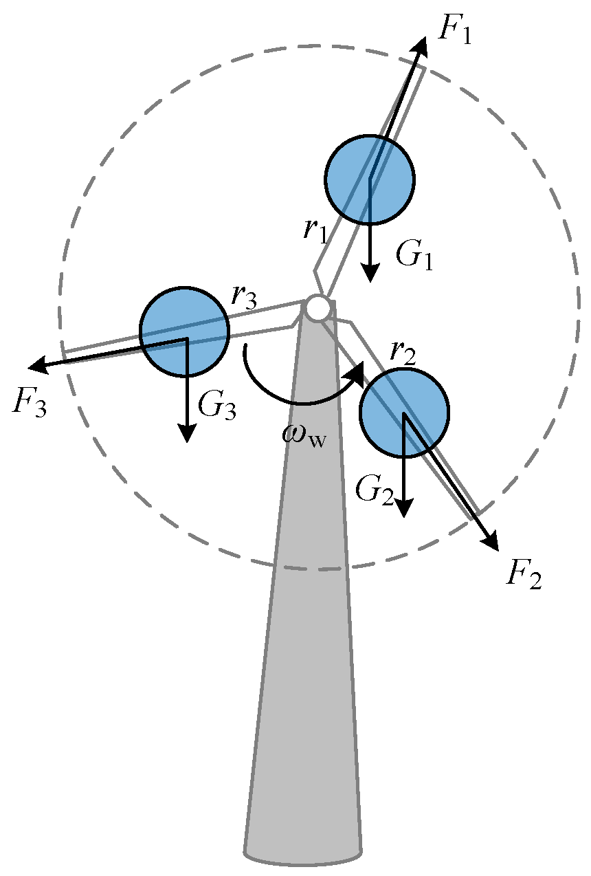
The research object of this paper is the 3-blade DFIG WT; Figure 1 is a schematic diagram of the 3-bladed WT. Each blade can be equivocated to a mass block with a distance of ri (i = 1, 2, 3) to the hub center and a mass of mi (i = 1, 2, 3). In Figure 1, Gi and Fi (i = 1, 2, 3) represent the gravity and centrifugal force of each blade, respectively. Under normal conditions, these three blades are equal in gravity and the centrifugal force. Since the centrifugal force intersects the axis of the hub center perpendicularly, the rotational torque of the rotor is not affected. The three blades have geometrical symmetry, so when the rotor rotates at angular velocity, , the torque generated by the gravity of the three blades is zero:
Under normal conditions, the torque of the drive transmission chain is completely derived from the aerodynamic torque. In this paper, the aerodynamic torque model is established by the WT characteristic curve in [11], as shown in Equation (2):
where is the torque of the rotor (N·m); is the air density (kg/m3); R is the rotor radius (m); is the wind speed at the height of the hub center (m/s); is the blade pitch angle (°); is the tip-speed ratio; is the rotor power coefficient; is the rotor angular velocity (rad/s). The presence of a trailing edge flap and the flapping angle may result in an aerodynamic torque imbalance, but its effect on torque is much less than the effect of mass imbalance on torque. In order to simplify the calculation process, their effect on torque is not considered when building the model.
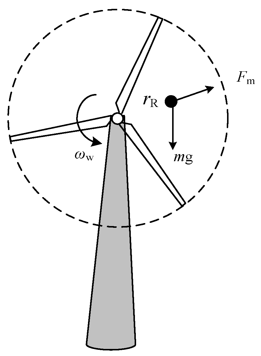
When the blade mass imbalance fault occurs, the mass of one or several blades increases, which can be equivalent to the presence of an unbalanced virtual mass block m [20] on the blade. The distance to the hub center is R; the block rotates together with the blade at an angular velocity, ; as shown in Figure 2, the force that the mass block is subjected to during the rotation mainly includes its gravity, mg, and centrifugal force, Fm. Under the action of gravity and centrifugal force, the WT transmission system will generate vibration along the main shaft. Because the tower has relatively high rigidity in the vertical direction, it will mainly cause periodic vibration of the blade and other structures in the horizontal direction. The vibration frequency is the base frequency of the rotor. The gravitational torque generated by the equivalent mass block affects the output rotor torque, Tw [21], and can be expressed as:
where ϕ is the initial position angle of the blade (rad).
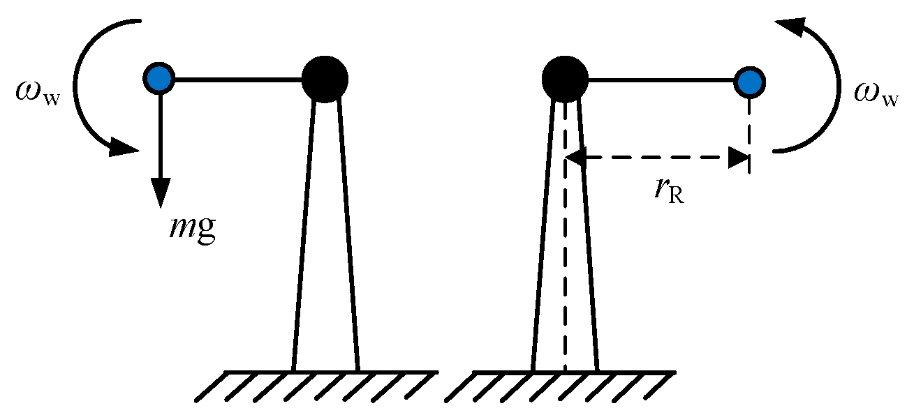
Figure 2 is a schematic diagram of the mass imbalance of a single blade of a WT. The equivalent mass block, m, rotates with the blade at a speed of , and the gravitational torque generated by it can cause fluctuations in the rotational speed of the main shaft. As shown in Figure 3, the mass imbalance will accelerate the rotational speed of the main shaft during the downward rotation from the top to the bottom and will decelerate the main shaft as the blade rotates from the bottom up to the top.
2.2. The Electromagnetic Power when Blade Mass Imbalance
In order to obtain the electromagnetic power signal under the blade mass imbalance fault state, it is necessary to establish the model of transmission chain and generator. Considering that the flexibility of the transmission chain of the WT will affect the electromagnetic power, this paper will equivalate the transmission chain of WT into two mass blocks: the rotor mass block and the gearbox and generator mass block. The elasticity and damping of the shaft between different mass blocks are considered.
The transmission system of a WT is generally composed of a blade rotor, hub, gearbox, and generator. Ignoring the damping and elasticity between the blade and hub of the WT and regarding them as one mass block; and regarding the generator and the gearbox as another mass block, equivalates the WT transmission system to a two-mass system while the elasticity and damping of the shaft between the two masses are considered.
The DFIG WT connects the rotor and the generator through the speed increasing gearbox, and the angular velocity of the generator rotor is equal to Nωw (N is the gearbox increase ratio). The increase and deceleration of the speed of the main shaft will be reflected according to the angular velocity of the generator rotor so that the generator rotor will have periodic fluctuations of speed increase and deceleration. The frequency is equal to the base frequency of rotor rotation. The two mass models can be expressed as:
where θs is the angle of torsion of the drive shaft (rad); ωe is the rotational speed of the generator (rad/s); Jw and Je are the rotational inertia of the rotor and the generator, respectively (kg·m2); Ks is the equivalent stiffness coefficient of the transmission chain; Bs is the damping coefficient; Tw is the aerodynamic torque of the rotor; Te is the electromagnetic torque of the generator.
where np is the pairs of poles; Lm is the mutual inductance between stator and rotor coaxial equivalent windings in d-q coordinate system; isd, isq, ird, and irq are the d and q axis components of the stator and rotor current.
According to the knowledge of electrical engineering and combined with Equation (5), the electromagnetic power of the generator obtained is:
where is the stator output rotational frequency.
So far, the DFIG model—including the rotor, the transmission chain, and the generator—has been established, and the torque generated by the blade mass imbalance has been introduced in the rotor part, so the response of the DFIG WT to the electromagnetic power under the fault can be simulated. Substituting these two equations into Equation (4) can establish the following relationship:
The simultaneous Equations (2), (3), (5), and (6) are available:
It can be known from Equation (8) that the introduction of blade mass imbalance causes the electromagnetic power to show the frequency of rotational frequency, and its amplitude should be .
3. Influence of Wind Shear and Tower Shadow Effect on Electromagnetic Power
In the WT fault diagnosis analysis, the wind speed model is calculated by the wind speed, VH, at the height of the hub center, and the change of the aerodynamic load on the blade does not be considered. In this paper, the equivalent wind speed model is used to simulate the influence of wind shear and tower shadow on mechanical torque by the wind speed fluctuation component; the equivalent wind speed model is proposed by Dale S.L.D. This model considers the wind shear effect and the tower shadow effect. The dynamic characteristics of the wind wheel are affected by the 3P pulsating component (3 is the number of blades, P is the rotor angular frequency) [16]. The wind speed in Equation (2) is replaced by the wind speed, VH, at the hub to the equivalent wind speed Veq, the equivalent wind speed, Veq, expression is [22,23]:
Vws is the wind shear component (m/s); Vis is the tower shadow effect component (m/s). They can be expressed as:
where R is the rotor radius (m); H is the height of the hub center (m); β is the blade azimuth angle (rad), βi (i = 1,2,3) is the blade azimuth angle of each blade (°); α is the wind shear exponent; A is the tower radius (m); and x is the distance from the blade origin to the tower midline (m).
Equation (10) is obtained by expanding the Taylor series; the deviation resulting from the expansion items increases rapidly when the length of blade is larger than 60 m. Generally, it will expand to the third item in the actual computing application, and the fourth item will be ignored. When the length of blade reaches 100 m, under the condition that the azimuth angle of the blade is π, the third term deviation is about −11.5%, and the fourth term deviation is about −4.6%. As shown in Figure 4, it can be seen that with the increase of R, the fourth term in the expansion of the Taylor series can no longer be ignored as high-order infinitesimal, so this paper expands to the fourth term when building the model.
Substituting Equations (10) and (11) into Equation (9), the equivalent wind speed obtained after simplification is:
According to Equation (14), the equivalent wind speed of three different types of WTs at the hub wind speed VH = 11 are plotted, and related parameters are shown in Table 1. As shown in Figure 5, these three curves clearly have a fixed fluctuate frequency.
Analyzing Equations (10), (11), and (14), the amplitudes of the wind shear and tower shadow component in the equivalent wind speed are related to the WT structural parameters and are proportional to the hub wind speed, VH; the base frequency is 3 times the wind rotor rotational speed, also known as the 3P (P is the wind rotor rotation frequency) frequencies f3p (Hz); the expression is:
where is the rotational speed of WT(r/min).
Replacing the wind speed at the hub center in Equation (2) with the equivalent wind speed including the wind speed at the hub, the wind shear component, and the tower shadow component, the aerodynamic torque of the WT under the equivalent wind speed is:
Combined with the influence of blade mass imbalance in Section 2, the influence of electromagnetic power with the blade mass imbalance under equivalent wind speed is obtained. It can be expressed as:
It can be seen from the foregoing analysis that, due to the existence of wind shear and tower shadow effect, the wind speed contains a sinusoidal component whose frequency is three times the frequency of the frequency, and the component can be replaced by ; the part other than this component can be represented by . Therefore, the equivalent wind speed can be rewritten as:
Substitute Equation (18) into Equation (17) can get:
Equation (17) shows that the fluctuation of electromagnetic torque and electromagnetic power caused by blade mass imbalance fault and equivalent wind speed—including wind shear and tower shadow effect—will appear at 1P, 3P, and 6P; The fluctuation at 1P is caused by the blade mass imbalance, and the fluctuations at 3P and 6P are caused by the equivalent wind speed.
4. Simulation Results and Analysis
4.1. Simulation Model and Parameters
In software FAST of NREL (The National Renewable Energy Laboratory), there are wind speed models which include wind shear and tower shadow effects. The interface of this software is simple, clear, and easy to operate, but it is not convenient for fault simulation [24]. In order to verify the correctness of the theoretical analysis described above, a 1.5 MW DFIG WT under the blade mass imbalance fault condition was built in the MATLAB/Simulink environment. This adds in the equivalent wind speed model, including wind shear and tower shadow effects; the model is shown in Figure 6. The parameters of the WTs simulated in this paper are shown in Table 2, and the simulation is carried out at a rated wind speed of 11 m/s.
The model mainly includes the equivalent wind speed model, the output torque model under blade mass imbalance, the transmission chain model, and the generator model. By changing the weight of the unbalanced mass block, it is possible to simulate the influence of different degrees of mass imbalance faults on the electromagnetic torque and electromagnetic power. The rotor side of the DFIG WT adopts the stator voltage directional vector control [25,26].
4.2. Fault Diagnosis Step
The blade mass imbalance fault diagnosis process of DFIG is shown in Figure 7 [27]. The choice of signal analysis method and diagnostic process are as follows:
- Step1. The electromagnetic torque and electromagnetic power under blade mass imbalance condition were measured, and then spectrum analysis on the signal by FFT was performed to obtain the characteristic frequency and its amplitude as the reference value;
- Step2. Electromagnetic torque and electromagnetic power were measured under the equivalent wind speed condition, blade mass imbalance condition, and then spectrum analysis was performed on the signal by FFT to obtain the characteristic frequency and its amplitude;
- Step3. Comparing the amplitude of the characteristic frequency when the signal only exists, the blade mass imbalance diagnosis, the amplitude of the characteristic frequency of the signal at the imbalance condition under the equivalent wind speed, and the fault characteristics and frequency were obtained;
- Step4. By comparing with the theoretical derivation results, the correctness of the conclusion in Section 3 was verified, and the fault characteristics summarized.
4.3. Fault Simulation Analysis
According to Section 2 and Section 3, the blade mass imbalance and the equivalent wind speed can cause fluctuation in the output torque of the drive chain, which is reflected in the Te and Pe at the generator. The correctness of the conclusions was verified through simulation and analysis. To quantitatively represent the degree of mass imbalance fault, the imbalance coefficient, b, was defined as:
To study the variation of the diagnosis characteristics under different degree of fault, b is set to 1%, 6%, and 10%, respectively. Figure 8 and Figure 9 show the time-domain plot of Te and Pe in normal conditions, only 10% mass imbalance, only the equivalent wind speed condition, and the equivalent wind speed, and 10% mass imbalance coexistence condition.
It can be seen from Figure 8 and Figure 9 that when the blade mass imbalance fault occurs, the Te and Pe show obvious periodic fluctuation; when the blade mass imbalance occurs under the equivalent wind speed, there are two kinds of different fluctuation periods (as shown in the circled part of Figure 8 and Figure 9). The longer period is roughly equivalent to the fluctuation period length of the equivalent wind speed; the shorter period is equivalent to the imbalance fluctuation period. Performing FFT processing on Te and Pe, the spectrum diagram can be obtained, as shown in Figure 10 and Figure 11.
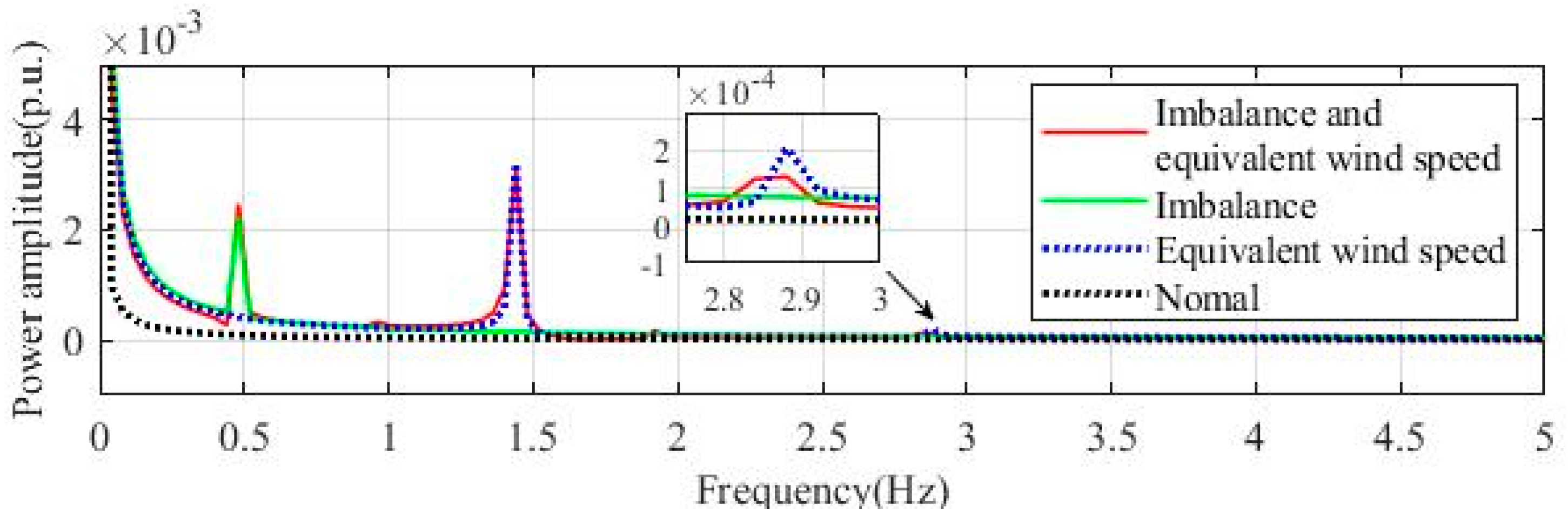
It can be found from the Te and Pe spectrum diagram that the Te and Pe signal of the imbalance fault has a sharp peak at f = 0.48 Hz, which corresponds to the frequency of the rotor rotation. When magnified, the spectrum can find a smaller peak at 2P; these conclusions are consistent with the conclusions in [11]. When the equivalent wind speed is added, it can be observed that, at 3P (f = 1.44 Hz), a sharp peak appears, and its amplitude is even slightly higher than 1P; after the figure is partially enlarged, it can be observed that there is also a much smaller peak at 6P (f = 2.88 Hz), which results from the equivalent wind speed. Therefore, in the actual fault diagnosis, when the amplitude at 3P is greater than 1P, it can also be judged that the blade mass imbalance fault has occurred.
Using the equation derived from the analysis, the calculation data of Pe at 6% imbalance condition under the equivalent wind speed was obtained, as was the spectrum curve. The spectrums obtained from the calculation data and the simulation data are drawn in the same figure, as shown in Figure 12. It can be seen that the two curves are very close, so it can be proven that the conclusions obtained by the simulation have a high reference value.
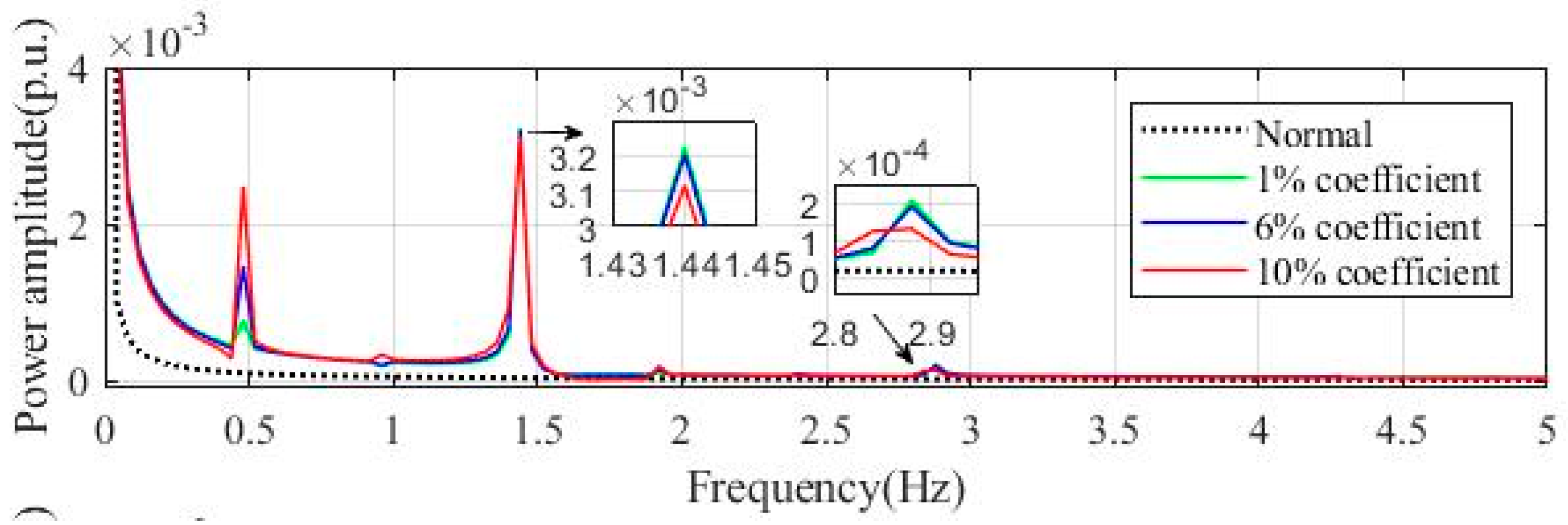
The electromagnetic power signals of the three different degrees of imbalance faults, at equivalent wind speed and the electromagnetic power signals and under normal conditions, are analyzed by FFT and plotted in the same figure. As shown in Figure 13, it can be seen that the greater the degree of fault is, the larger the amplitude at 1P, and the more obvious the fault characteristics. However, the amplitude at 3P and 6P does not change much with the increase of the degree of imbalance fault. Therefore, it is known that the faults at the 3P and 6P are mainly due to the existence of the equivalent wind speed, and this is the same as the conclusion drawn in the previous chapter.
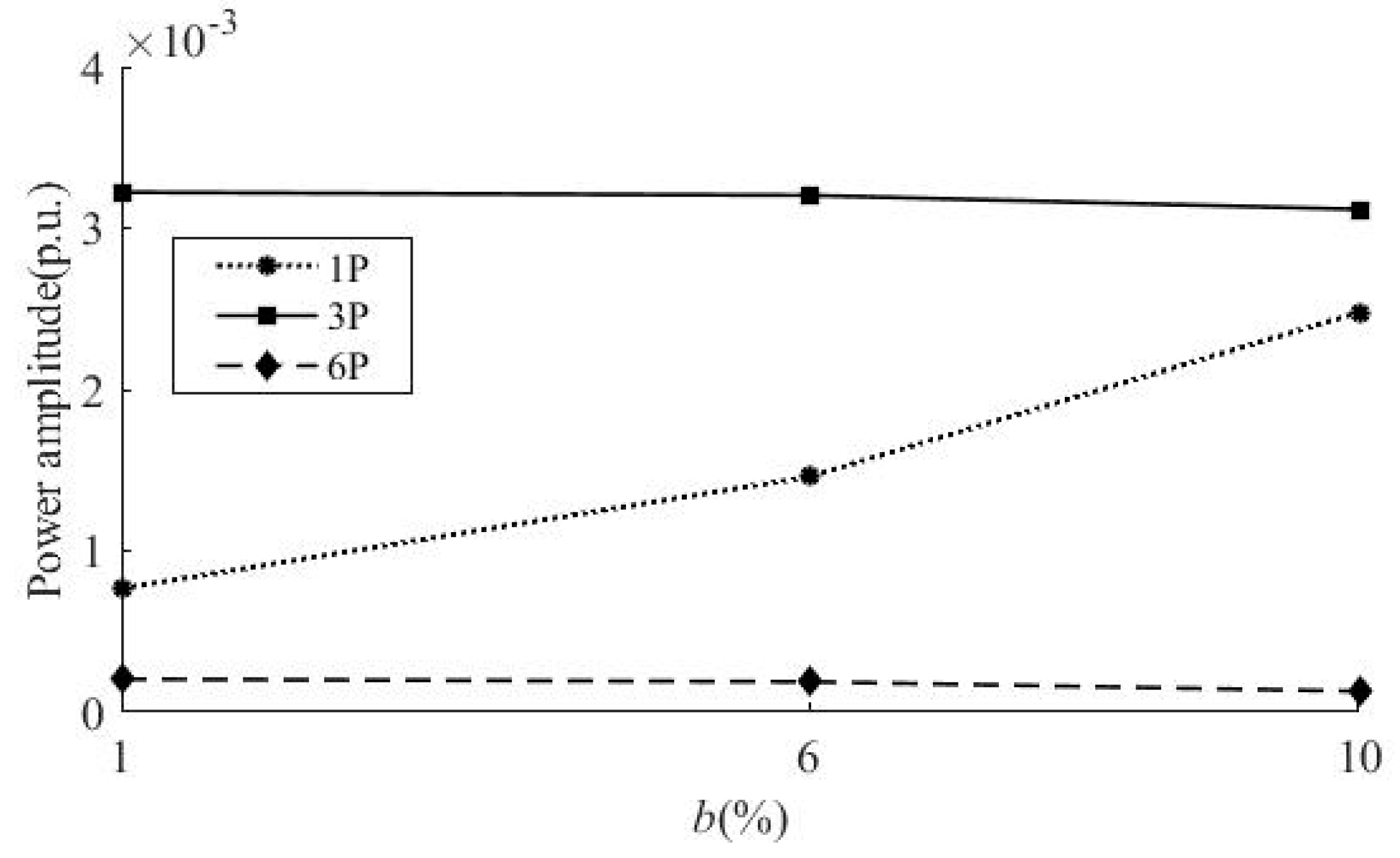
The corresponding amplitudes at 1P, 3P, and 6P under different fault levels are listed, as shown in Table 3, and drawn as a line graph, as shown in Figure 14. It can be seen that as the degree of imbalance increases, the amplitude at 1P increases significantly, while the amplitude at 3P and 6P changes little, consistent with the foregoing conclusions.
5. Conclusions
Based on the mechanism of blade mass imbalance, considering the spatiotemporal distribution of natural wind speed and the influence of wind shear and tower shadow effect, the equivalent wind speed model is established, and the electrical characteristics of the DFIG WT are analyzed. Via the theoretical and simulation analysis, the following conclusions were obtained:
- (1)
- The blade mass imbalance of the DFIG will cause fluctuations in the output torque of the wind rotor. The presence of wind shear and tower shadow effect will also cause fluctuations in the output torque and will pass through the transmission chain reflect in electromagnetic torque and electromagnetic power. So it is feasible to use an electrical signal to detect the fault.
- (2)
- Considering only the blade mass imbalance under the average wind speed at the hub will cause the electromagnetic torque and electromagnetic power to fluctuate at the 1P frequency.
- (3)
- Considering the spatiotemporal distribution of wind speed and the influence of wind shear and tower shadow effect, the blade mass imbalance fault will cause fluctuation at the frequency of 1P, 3P, and 6P on electromagnetic power, in which the fluctuation at 1P is caused by the mass imbalance fault while the fluctuation at 3P and 6P are caused by wind shear and tower shadow effect; the amplitude of the fluctuation at 1P is proportional to the degree of the imbalance fault.
Due to the introduction of the equivalent wind speed model based on the original blade mass imbalance fault diagnosis, the fault diagnosis method and process were improved, which provides a way for the diagnosis and identification of the blade mass imbalance fault in DFIG application. The signal is analyzed and processed by FFT in this paper. In future research, a variety of signal processing methods, such as wavelet transform, may be used to extract the fault characteristic frequency, and the extraction effect will be compared to find the most suitable signal processing method for blade mass imbalance fault diagnosis. In addition, this paper only discusses the failure situation of a single WT and does not consider other possible factors that may affect the wind speed in the wind farm, such as wake effects. In future research, these issues may be taken into consideration.
Author Contributions
Conceptualization, S.W. and K.C.; methodology, K.C.; software, K.C.; formal analysis, K.C.; investigation, K.C.; resources, X.S.; writing—original draft preparation, K.C.; writing—review and editing, K.C.; visualization, X.W.; supervision, X.S.; project administration, S.W.; funding acquisition, S.W.
Funding
This research was funded by the National Natural Science Foundation of China, grant number 51777075; the Fundamental Research Funds for the Central Universities, grant number 2018MS121; Natural Science Foundation of Hebei Province, grant number E2019502064. The authors are grateful for these supports.
Conflicts of Interest
The authors declare no conflict of interest.
Abbreviations
The following abbreviations are used in this manuscript:
| b | Imbalance coefficient |
| Bs | Damping coefficient |
| Cp (σ, λ) | Rotor power coefficient |
| DFIG | Doubly-fed induction generator |
| f1 | Stator output rotational frequency |
| Fi | Centrifugal force of each blade |
| Gi | Gravity force of each blade |
| ird | d axis components of the rotor current |
| irq | q axis components of the rotor current |
| isd | d axis components of the stator current |
| isq | q axis components of the stator current |
| Jw | Rotational inertia of the turbine |
| Je | Rotational inertia the generator respectively |
| Ks | Equivalent stiffness coefficient of the transmission chain |
| Lm | Mutual inductance |
| mi | Mass of the equivalent mass block |
| np | Pairs of poles |
| nω | Rotational speed |
| Pe | Electromagnetic power |
| ri | The distance between equivalent mass block to the hub center |
| R | Rotor radius |
| Te | Electromagnetic torque of the generator |
| Tw | Aerodynamic torque of the rotor |
| Torque of the rotor | |
| Veq | Equivalent wind speed |
| VH | Wind speed |
| Vts | Tower shadow effect component |
| Vws | Wind shear component |
| WT | Wind turbine |
| ωe | Rotational speed of the generator |
| ωw | Rotor angular velocity |
| λ | Tip-speed ratio |
| σ | Blade pitch angle |
| ρ | Air density |
| ϕ | Initial position angle of the blade |
| θs | Angle of torsion of the drive shaft |
References
- Cai, X.; Pan, P.; Zhu, J.; Gu, R.R. Blade of Wind Wurbines; China Water Power Press: Beijing, China, 2014. [Google Scholar]
- Rabanal, A.; Ulazia, A.; Ibarra-Berastegi, G.; Sáenz, J.; Elosegui, U. MIDAS: A Benchmarking Multi-Criteria Method for the Identification of Defective Anemometers in Wind Farms. Energies 2018, 12, 28. [Google Scholar] [CrossRef]
- Astolfi, D. A Study of the Impact of Pitch Misalignment on Wind Turbine Performance. Machines 2019, 7, 8. [Google Scholar] [CrossRef]
- Elosegui, U.; Egana, I.; Ulazia, A.; Ibarra-Berastegi, G. Pitch Angle Misalignment Correction Based on Benchmarking and Laser Scanner Measurement in Wind Farms. Energies 2018, 11, 3357. [Google Scholar] [CrossRef]
- Astolfi, D. Castellani Francesco. Wind Turbine Power Curve Upgrades: Part II. Energies 2019, 12, 1503. [Google Scholar] [CrossRef]
- Ramlau, R.; Niebsch, J. Imbalance Estimation without Test Asses for Wind Turbines. J. Sol. Energy Eng. 2009, 131, 011010. [Google Scholar] [CrossRef]
- Jiang, D.; Huang, Q.; Hong, L. Theoretical and Experimental Study on Wind Wheel Imbalance for a Wind Turbine. In Proceedings of the World Non-Grid-Connected Wind Power and Energy Conference, Nanjing, China, 24–26 September 2009; pp. 351–355. [Google Scholar]
- Zhao, M.; Jiang, D.; Li, S. Research on Fault Mechanism of Icing of Wind Turbine Blades. In Proceedings of the World Non-Grid-Connected Wind Power and Energy Conference, Nanjing, China, 24–26 September 2009; pp. 356–359. [Google Scholar]
- Gong, X.; Qiao, W. Simulation Investigation of Wind Turbine Imbalance Faults. In Proceedings of the International Conference on Power System Technology, Hangzhou, China, 24–28 October 2010; pp. 1–7. [Google Scholar]
- Caselitz, P.; Giebhardt, J. Rotor Condition Monitoring for Improved Operational Safety of Offshore Wind Energy Converters. J. Sol. Energy Eng. 2005, 127, 253–261. [Google Scholar] [CrossRef]
- Yang, T.; Ren, Y.; Liu, X.; Huang, S.; Gao, W. Research on the Modeling and Simulation of Wind Turbine Rotor Imbalance Fault. J. Mech.Eng. 2012, 48, 130–135. [Google Scholar] [CrossRef]
- Xiang, G.; Wei, Q. Imbalance Fault Detection of Direct-drive Wind Turbines Using Generator Current Signals. IEEE Tran. Energy Convers. 2012, 27, 468–476. [Google Scholar]
- Hang, J.; Zhang, J.Z.; Cheng, M.; Zhu, Y.; Zhang, B.F. Fault Diagnosis of Blade Imbalance and Winding Asymmetry of Direct-driven Wind Turbine with Permanent Magnet Synchronous Generator. Proc. CSEE 2014, 34, 1384–1391. [Google Scholar]
- Deng, X.; Pan, Q.; Gao, Q. Research on the Modeling and Simulation of Permanent Magnet Direct-driven Wind Turbine Rotor Imbalance Fault. Power Syst. Prot. Control 2018, 46, 35–40. [Google Scholar]
- Sheng, X.; Wan, S.; Li, Y.; Cheng, L. Characteristic Analysis of Doubly-Fed Induction Generator under Blade Mass Imbalance Fault. Acta Energy Sol. Sin. 2017, 38, 1324–1332. [Google Scholar]
- Dolan, D.S.L.; Lehn, P.W. Simulation model of wind turbine 3p torque oscillations due to wind shear and tower shadow(Article). IEEE Trans. Energy Convers. 2006, 21, 717–724. [Google Scholar] [CrossRef]
- Fadaeinedjad, R.; Moschopoulos, G.; Moallem, M. The Impact of Tower Shadow, Taw Error, and Wind Shears on Power Quality in a Wind–diesel System. IEEE Trans. Energy Convers. 2009, 24, 102–111. [Google Scholar] [CrossRef]
- McSwiggan, D.; Littler, T.; Morrow, D.J.; Kennedy, J. A Study of Tower Shadow Effect on Fixed-speed Wind Turbines. In Proceedings of the 43rd International Universities Power Engineering Conference, Padova, Italy, 1–4 September 2008; pp. 1–5. [Google Scholar]
- Wen, B.; Wei, S.; Wei, K.; Yang, W.; Peng, Z.; Chu, F. Influences of Wind Shear and Tower Shadow on the Power Output of Wind Turbine. J. Mech. Eng. 2018, 54, 124–132. [Google Scholar] [CrossRef]
- Slootweg, J.G.; Polinder, H. Dynamic Modeling of a Wind Turbine with Doubly Fed Induction Generator. In Proceedings of the 2001 IEEE Power Engineering Society Summer Meeting, Vancouver, BC, Canada, 15–19 July 2001; pp. 644–649. [Google Scholar]
- Jenny, N.; Ronny, R.; Thien, T.N. Mass and Aerodynamic Imbalance Estimates of Wind Turbines. Energies 2010, 3, 696–710. [Google Scholar] [Green Version]
- Elkinton, M.R.; Rogers, A.L.; McGowan, J.G. An Investigation of Wind-shear Models and Experimental Data Trends for Different Terrains. Wind Eng. 2006, 30, 341–350. [Google Scholar] [CrossRef]
- Rehman, S.; Al-Abbadi, N.M. Wind shear coefficients and their effect on energy production. Energy Convers. Manag. 2005, 46, 2578–2591. [Google Scholar] [CrossRef]
- NWTC Information Portal. Available online: https://nwtc.nrel.gov/FAST (accessed on 3 August 2019).
- Gardels, D.J.; Qiao, W.; Gong, X. Simulation Studies on Imbalance Faults of Wind Turbines. In Proceedings of the 2010 IEEE Power & Energy Society General Meeting, Providence, RI, USA, 25–29 July 2010; pp. 1–5. [Google Scholar]
- He, Y.; Hu, J.; Xu, L. Operation and Control of Grid Doubly-fed Induction Generator; China Electric Power Press: Beijing, China, 2011. [Google Scholar]
- Wan, S.; Cheng, L.; Sheng, X. Numerical Analysis of the Spatial Distribution of Equivalent Wind Speeds inLarge-scale Wind Turbines. J. Mech. Sci. Technol. 2017, 31, 965–974. [Google Scholar] [CrossRef]
Figure 1.
3-bladed wind turbine schematic diagram.

Figure 2.
Force analysis of the imbalanced mass block.

Figure 3.
Model of blade mass imbalance.

Figure 4.
Deviations of high order components of Taylor series expansion.

Figure 5.
Equivalent wind speed corresponding to different wind turbines.
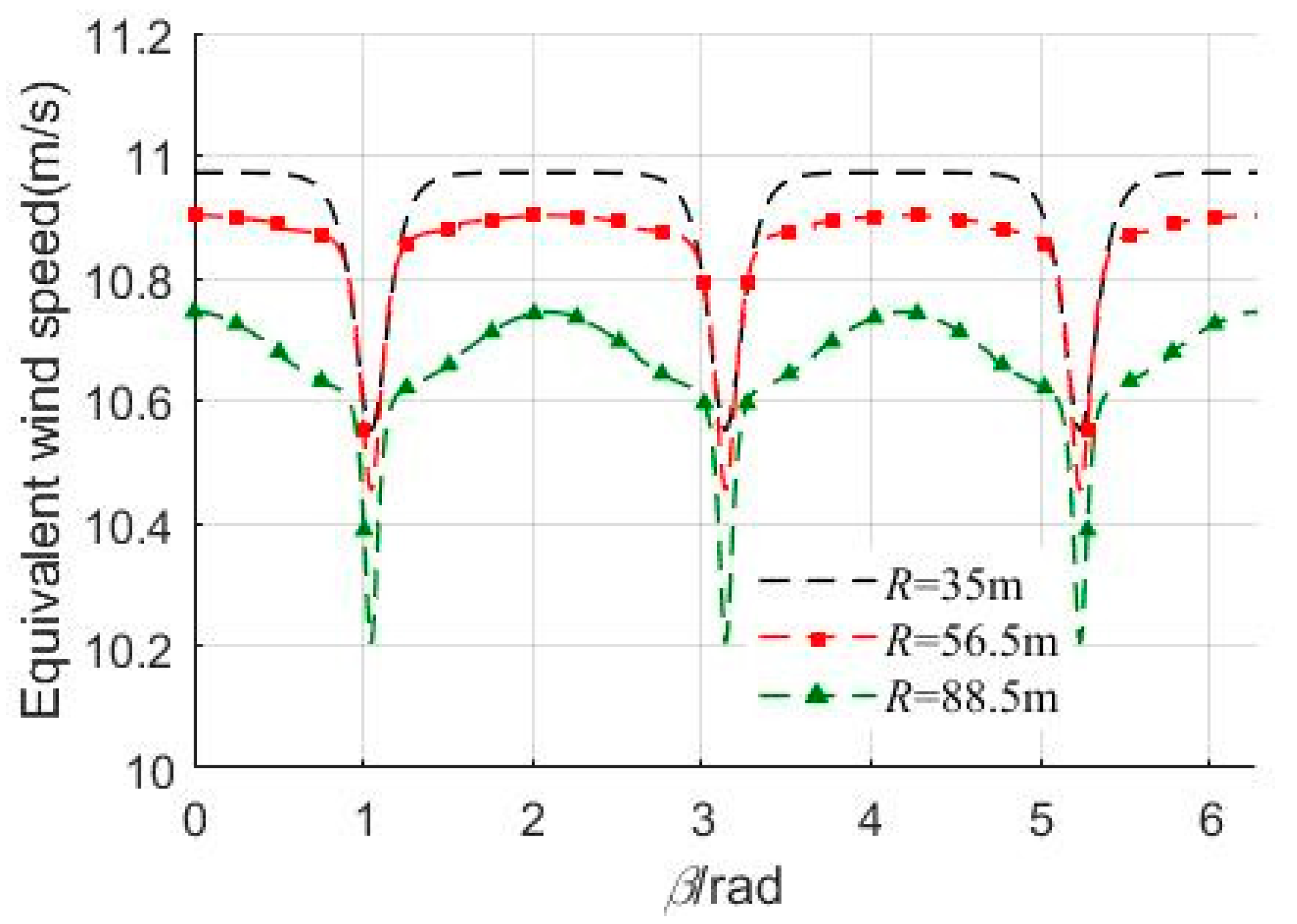
Figure 6.
Simulation platform.

Figure 7.
Flow diagram of fault diagnosis.

Figure 8.
Electromagnetic torque time-domain waveform.
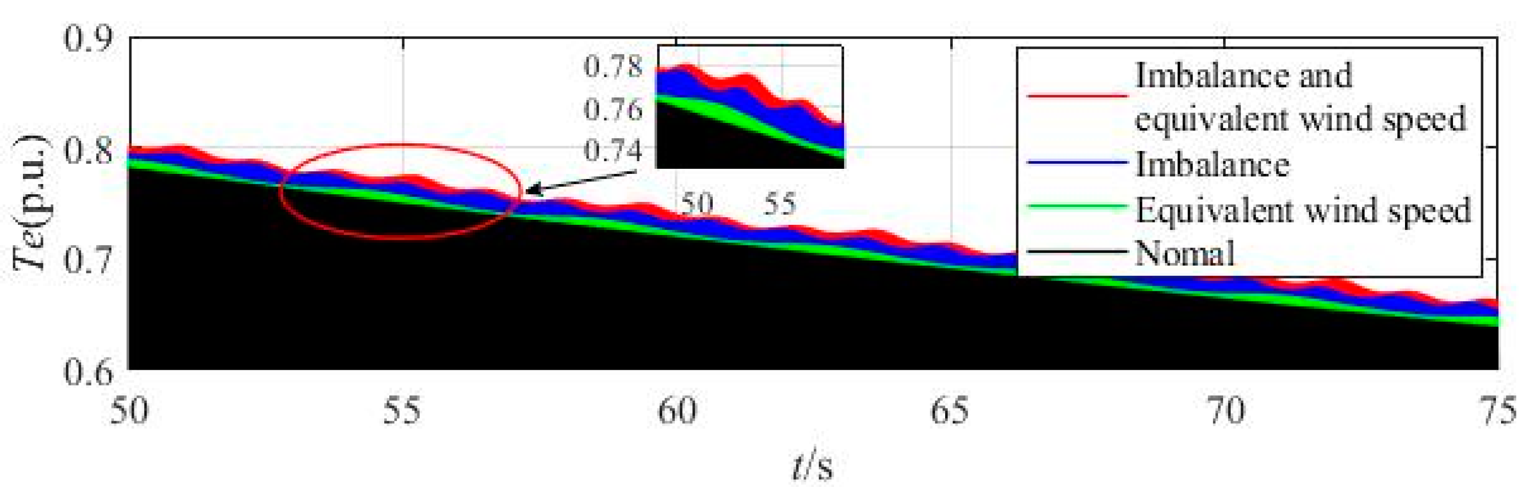
Figure 9.
Electromagnetic power time-domain waveform.

Figure 10.
Spectrum of electromagnetic torque.
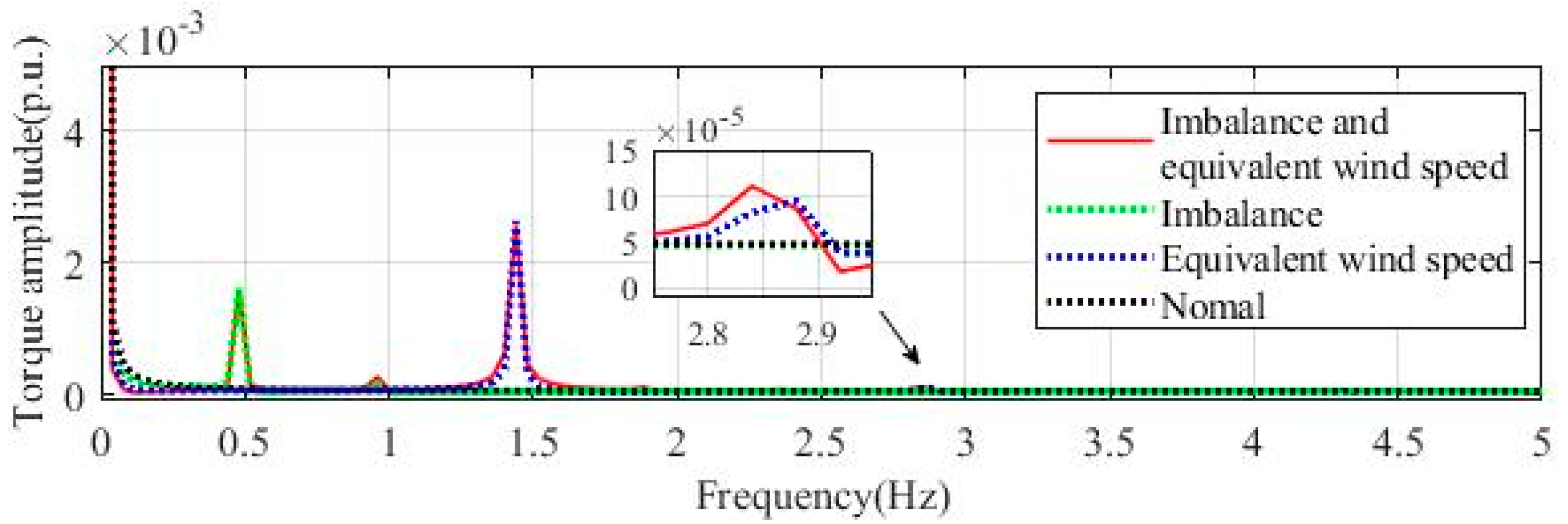
Figure 11.
Spectrum of electromagnetic power.

Figure 12.
Spectrums obtained from the calculation data and the simulation data.
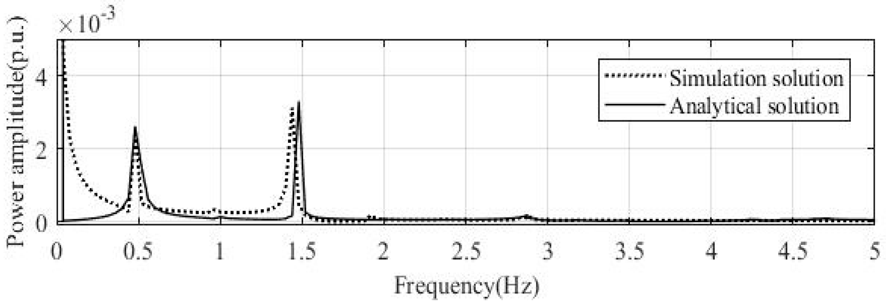
Figure 13.
Electromagnetic power spectrum under b = 1%, 6%, and 10% state.

Figure 14.
Amplitude of fault frequency for different degree of imbalance.

Table 1.
Parameter values of 3 different typical wind turbines.
| P (kW) | R (m) | H (m) | A (m) | x (m) |
|---|---|---|---|---|
| 1500 | 35 | 70 | 4.0/2.8 (3.4) | 4.5 |
| 2500 | 56.5 | 87 | 4.6/3.2 (3.9) | 5.2 |
| 8000 | 88.5 | 131 | 6.0/4.0 (5.0) | 7.5 |
Table 2.
Parameters of 1.5MW DFIG wind turbine.
| Parameters | Value | Parameters | Value |
|---|---|---|---|
| Rated power (MW) | 1.5 | Stator resistance (p.u.) | 0.023 |
| Rated speed (m/s) | 11 | Stator leakage inductance (p.u.) | 0.18 |
| Optimum tip speed ratio | 8.7 | Rotor resistance (p.u.) | 0.016 |
| Optimum rotor power coefficient | 0.38 | Rotor leakage inductance (p.u.) | 0.16 |
| Blade diameter (m) | 35 | Pairs of poles | 3 |
| Tower diameter (m) | 1.7 | Inertia constant (s) | 0.685 |
| Center height of the hub (m) | 70 | Air density (kg/m3) | 1.225 |
Table 3.
Amplitude of fault frequency for different degree of imbalance.
| Imbalance Fault Degrees | Frequency (Hz) | ||
|---|---|---|---|
| 0.48 Hz (f1P) | 1.44 Hz (f3P) | 2.88 Hz (f6P) | |
| 1% | 0.000767 | 0.003222 | 0.000205 |
| 6% | 0.001459 | 0.003203 | 0.000189 |
| 10% | 0.002478 | 0.003116 | 0.000130 |
© 2019 by the authors. Licensee MDPI, Basel, Switzerland. This article is an open access article distributed under the terms and conditions of the Creative Commons Attribution (CC BY) license (http://creativecommons.org/licenses/by/4.0/).
Share and Cite
MDPI and ACS Style
Wan, S.; Cheng, K.; Sheng, X.; Wang, X. Characteristic Analysis of DFIG Wind Turbine under Blade Mass Imbalance Fault in View of Wind Speed Spatiotemporal Distribution. Energies 2019, 12, 3178. https://doi.org/10.3390/en12163178
AMA Style
Wan S, Cheng K, Sheng X, Wang X. Characteristic Analysis of DFIG Wind Turbine under Blade Mass Imbalance Fault in View of Wind Speed Spatiotemporal Distribution. Energies. 2019; 12(16):3178. https://doi.org/10.3390/en12163178
Chicago/Turabian StyleWan, Shuting, Kanru Cheng, Xiaoling Sheng, and Xuan Wang. 2019. "Characteristic Analysis of DFIG Wind Turbine under Blade Mass Imbalance Fault in View of Wind Speed Spatiotemporal Distribution" Energies 12, no. 16: 3178. https://doi.org/10.3390/en12163178
Note that from the first issue of 2016, this journal uses article numbers instead of page numbers. See further details here.