Evaluation of Efficient Operation for Electromechanical Brake Using Maximum Torque per Ampere Control

Department of Next Generation Railroad Train Research Center, Korea Railroad Research Institute, 176, Cheoldo Bangmulgwan-ro, Uiwang-si, Gyeonggi-Do 437-757, Korea
*
Author to whom correspondence should be addressed.
Energies 2019, 12(10), 1869; https://doi.org/10.3390/en12101869
Submission received: 25 April 2019
/
Revised: 13 May 2019
/
Accepted: 14 May 2019
/
Published: 16 May 2019
Abstract
:This paper deals with efficient operation method for the electromechanical brake (EMB). A three-phase interior permanent magnet synchronous motor (IPMSM) is applied to the EMB operation. A current controller, speed controller, and position controller based on proportional-integral (PI) control are used to drive the IPMSM. Maximum torque per ampere (MTPA) control is applied to the current controller to perform efficient control. For MTPA control, the angle β is calculated from total input current, and the synchronous frame d–q axis current reference is determined by the angle β. The IPMSM is designed and analyzed with finite element analysis (FEA) software and current control is simulated by Matlab/Simulink using a motor model designed by FEA software. The simulation results were verified to compare with experimental results that are input current and clamping force of caliper. In addition, the experimental results showed that the energy consumption is reduced by MTPA.
1. Introduction
The electromechanical brake (EMB) uses the rotational motion of the motor to move the caliper to exert clamping force on the brake disc. The development of the initial EMB was actively carried out in the automotive field to replace the hydraulic brake [1,2].
Due to the development of the manufacturing technology of the motor and inverter, many researches are being carried out to improve the performance of EMB. EMB control methods have been studied: clamping force control by cascade connection of position, velocity, and current controller based on PID control [3,4]; clamping force control using sliding mode controller [5]; adaptive sliding mode control using neural network to estimate disturbance [6]; estimation of clamping force considering gear friction [7]; predictive control of clamping force by rotor position due to limitation of force sensor space [8]; and observer-based sensor-less robust force control method [9]. Despite the number of studies, improving energy saving using efficient control methods remains to be explored.
In the field of railroads, applying the EMB to the brake system has attracted attention as an alternative to the existing pneumatic braking system. The EMB minimizes the total volume of the brake system by up to 50%, eliminating unnecessary space-consuming equipment such as the air compressor, brake air container, pipeline for air, and valves, and can perform high-precision braking control and shorten the latency time by fast-response control. The brake system is considered as a safety device for train components. Even though the power supply is disconnected from external causes, the EMB must continue to be powered. Therefore, since the power input of inverter for EMB operation is connected to the battery system of the train, EMB requires efficient control to achieve energy savings. There are many studies that apply maximum torque per ampere (MTPA) control when the three-phase interior permanent magnet synchronous motor (IPMSM) is operating in normal rotation. However, experimental results on the motor stall condition have not been introduced. In this paper, three-phase IPMSM and a MTPA control scheme are suggested for EMB system. The experiment evaluation results, in terms of efficient driving when MTPA control is applied in the stall condition of IPMSM, are presented.
This research study includes simulation and experimental results of the EMB system. The IPMSM was designed and analyzed as electromechanical design software JMAG(Ver. 17.0, JSOL, Corporation, JAPAN). The IPMSM model was created in JMAG-RT and a cosimulation method was performed with the JMAG motor model using Matlab/Simulink(R2018a, MathWorks, Inc., Natick, MA, USA). This cosimulation method can consider harmonics from material, slot shape, magnet position etc., as well as motor torque output. In order to reduce the input current, the MTPA control method was applied to EMB operation. The simulation results were verified to compare with experimental results that are input current and clamping force of caliper. In addition, the experimental results showed that the energy consumption is reduced by the proposed control method.
2. Structure of EMB and IPMSM Specification
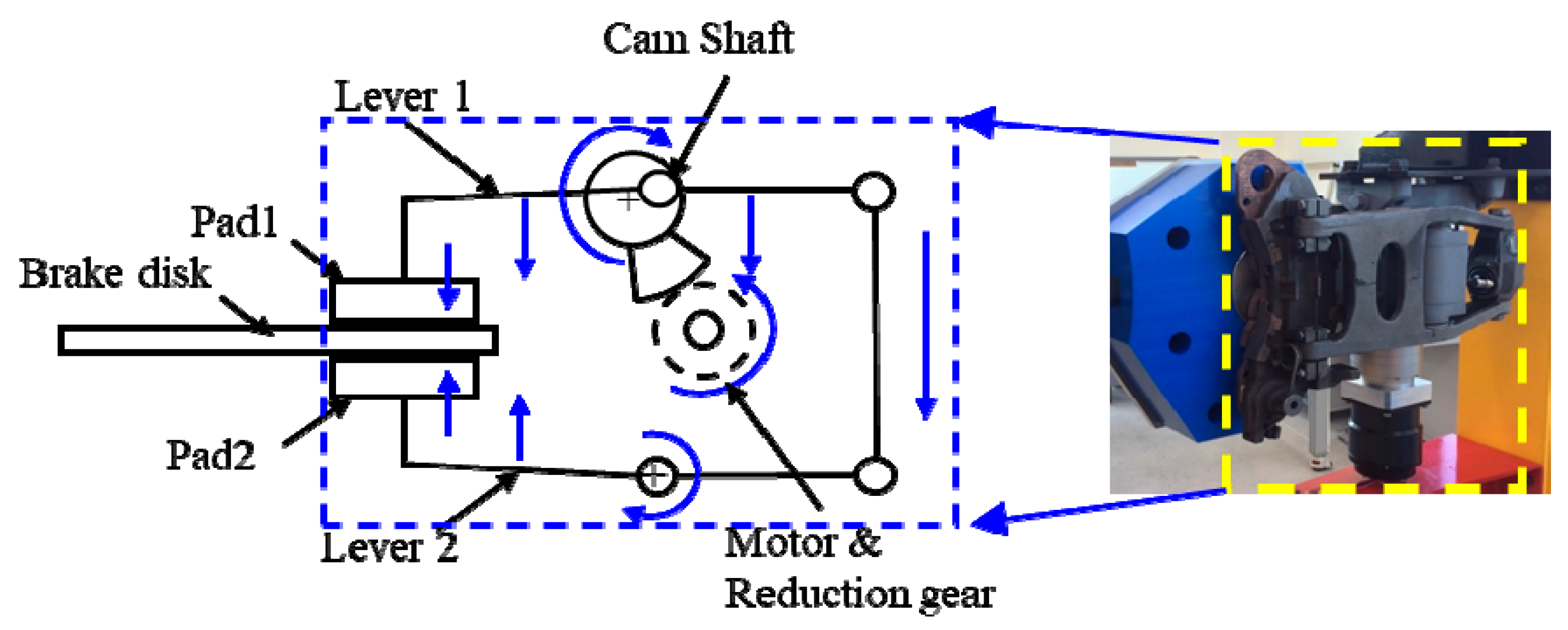
Figure 1 shows the EMB structure. When the brake is activated, the motor generates rotational torque that is transmitted to the camshaft at a reduction gear ratio. The rotational motion of the motor is changed from camshaft to linear motion and lever 1 and lever 2 pushed in the opposite direction. The disc pads connected to levers move toward the brake disc and clamping force are generated between the pads and brake disc. At this time, the motor is continuously stalled.
The motor type to rotate driving shaft that is applied is the IPMSM. Depending on the control method, the IPMSM can be used magnet torque and reluctance torque together because of the position of the permanent magnet installed in the rotor. The IPMSM provides a smaller volume and higher efficiency compared to the same size induction motor and SPMSM.
To design the IPMSM, the maximum clamping force target was selected 54 kN, which is the emergency braking reference of Korea’s high-speed train (HST). The reduction gear ratio of the motor shown in Figure 1 is ~290:1 and, in order to satisfy clamping force reference, the IPMSM output torque must be ~2 Nm. According to the EMB braking time specification, the camshaft rotational angular velocity should be 54 deg/s. At the reduction ratio, the angular velocity of motor is 263 rad/s. Therefore, the motor output needed to satisfy the clamping force reference value can be expressed as
where is the IPMSM power output, is torque output, and is angular velocity.
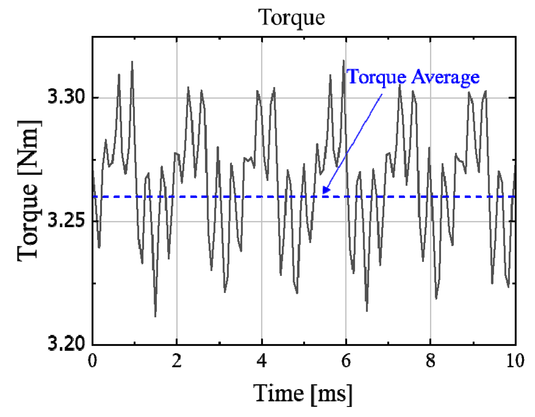
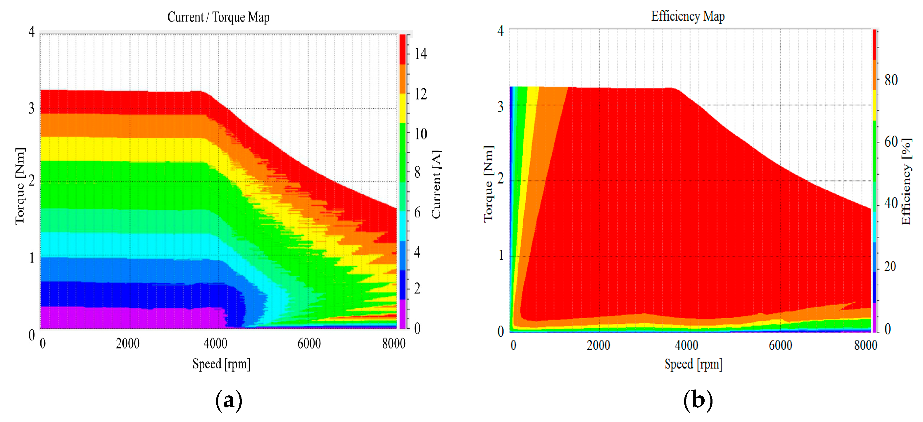
The purpose of the IPMSM design process is to create an IPMSM model block and show the results of cosimulation of MTPA control using a FEM tool and Matlab/Simulink. The IPMSM is designed with a distributed winding of four poles and 15 slots. The torque output is met within the allowable size of the IPMSM, and the permanent magnet width and angular position have been adjusted to improve torque ripple. Figure 2 and Figure 3 show the motor torque output, current, and an efficiency map of IPMSM according to the JMAG finite element analysis (FEA) results.
The torque output average is 3.27 Nm at 15 A input current. Compared to the 2 Nm mentioned above, the output torque margin is over 60% and the ripple rate is ± 0.03 Nm.
Figure 3 shows the motor torque output and efficiency map according to motor speed and input current. The end point speed of the constant torque is ~3600 rpm, and shows that the input current and output torque are linear in constant torque range. Since the output torque is required to be 2 Nm at 2500 rpm, as per Equation (1), the motor torque specification is satisfied with sufficient margin as shown in Figure 3a. Figure 3b shows the efficiency map according to the maximum power control on JMAG. The efficiency is greater than 95% near 2500 rpm. However since the EMB mainly operates in the low speed range when the brake is operated, the IPMSM operates in the low efficiency region. In addition, the efficiency of the reduction gear has to be considered. Therefore, it is necessary to design the IPMSM considering the sufficient output margin.
Table 1 shows the specifications of IPMSM mentioned in the above equation and design procedure. Compared to the calculation of Equation (1), the motor output power is ~1000 W, which is twice the minimum required motor power output.
3. Current Control of IPMSM
An IPMSM mathematical model is required for vector control. The voltage equation of the synchronous d–q axis frame for IPMSM can be expressed as [10]
where is angular velocity, is resistance of stator, and represent the d–q axis inductance of the stator, and are synchronous d–q axis current of stator, and is flux linkage.
From Equations (2) and (3) the output torque of IPMSM is expressed the sum of the magnet torque and the reluctance torque as
where is the number of poles.
Due to the insertion structure of the magnet, the inductance of the q-axis is larger than that of the d-axis. If IPMSM is controlled with , additional reluctance torque can be obtained from Equation (4).
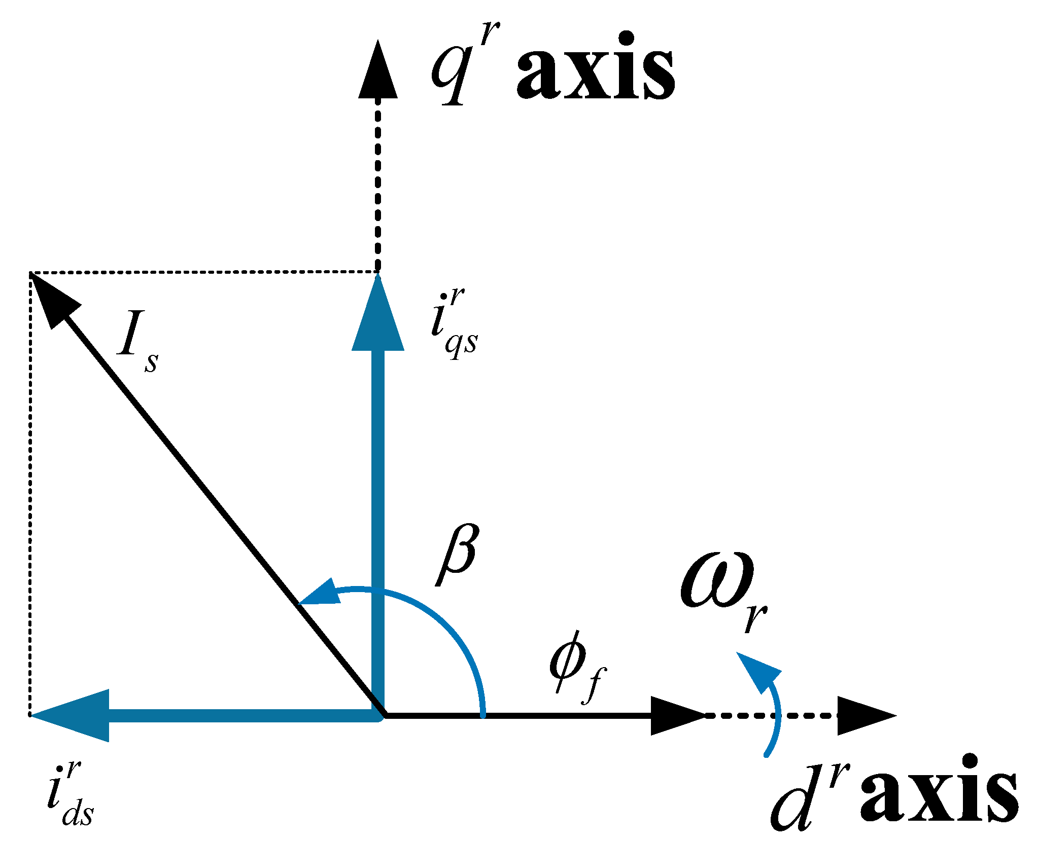
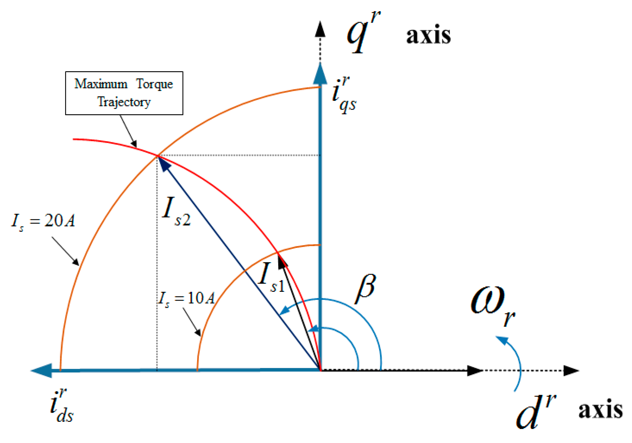
Figure 4 shows the angle relationship according to the control current of and . is the angle between and . The output torque of Equation (4) is expressed in terms of and as in Equation (5). Equation (6) is the derivative with respect to the angle of the Equation (5). The maximum torque point occurs when Equation (6) is zero. Therefore, the angle is expressed in terms of the input current as shown in Equation (7) [11].
From the relationship between and , as shown in Figure 4, the synchronous d–q axis current and of stator can be calculated for the MTPA control as follows
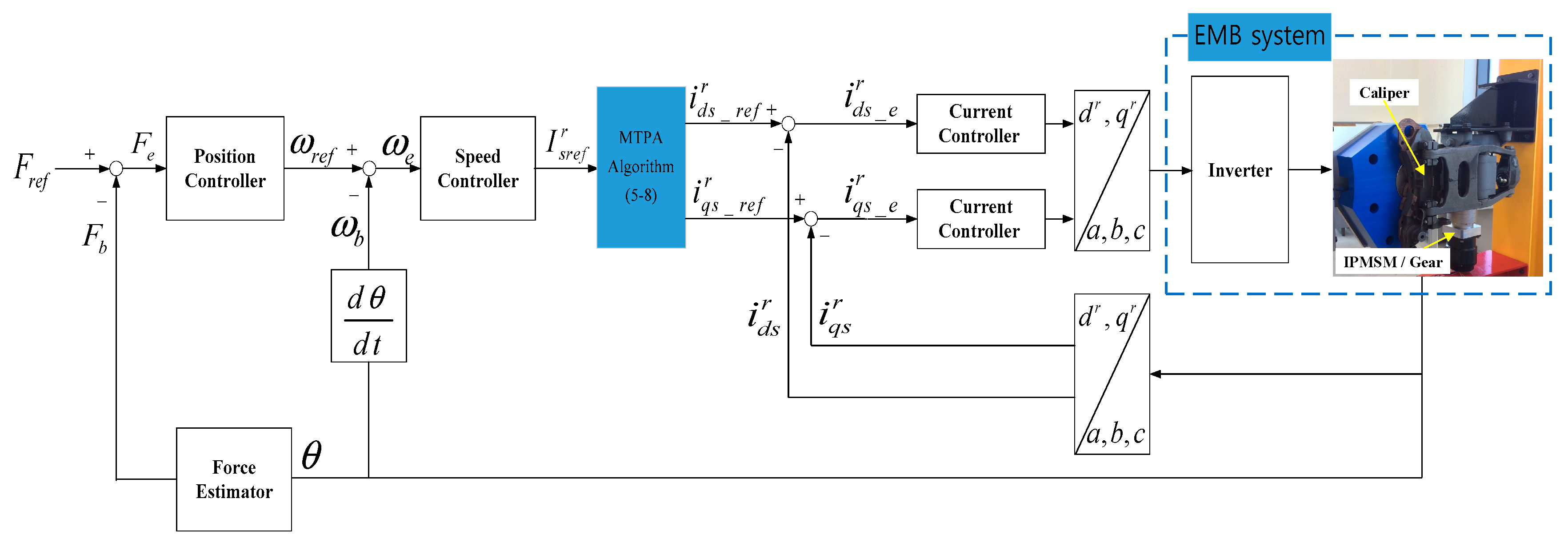
Figure 5 shows the IPMSM control scheme for the EMB. In this paper, the clamping force controller for EMB consists of three PI controllers, which are position, speed and current controllers. The three-phase current and angular displacement () can receive feedback from the IPMSM installed in the calipers. The synchronous frame d–q axis current can be calculated by the current output of IPMSM. Angular displacement from the resolver is converted to clamping force feedback () using a simple first-order equation force estimator. The MTPA algorithm block uses the total input reference current of the stator , which is the output of speed controller. According to Equations (5)–(8), and are calculated. The current controller gain can be selected generally as follows
where and are d–q axis proportional gain, is integral gain, and is bandwidth of controller. Based on the output voltage reference of the current controller, EMB system is generated at the MTPA output.
Figure 6 shows an example of the maximum torque trajectory based on synchronous frame d–q axis current reference. From the Table 1, when input stator current is 10 A and 20 A, the angle is calculated as ~114° and 122°. From Equations (7) and (8), according to the angle , the points can be produced and connected with one red color curve like as Figure 6. This curve can produce maximum torque depending on the input stator current [12].
4. Simulation Results of the Current Control for IPMSM
Simulation results were performed to verify the current control and output torque of the IPMSM according to MTPA. In this paper, the IPMSM model designed in the previous section was used instead of the Matlab/Simulink model to account for FEA results. In addition, Matlab/Simulink is used for current control of the MTPA algorithm. As mention above, the cosimulation method can consider loss and harmonics from material, slot shape, magnet position, etc., as well as motor torque output.
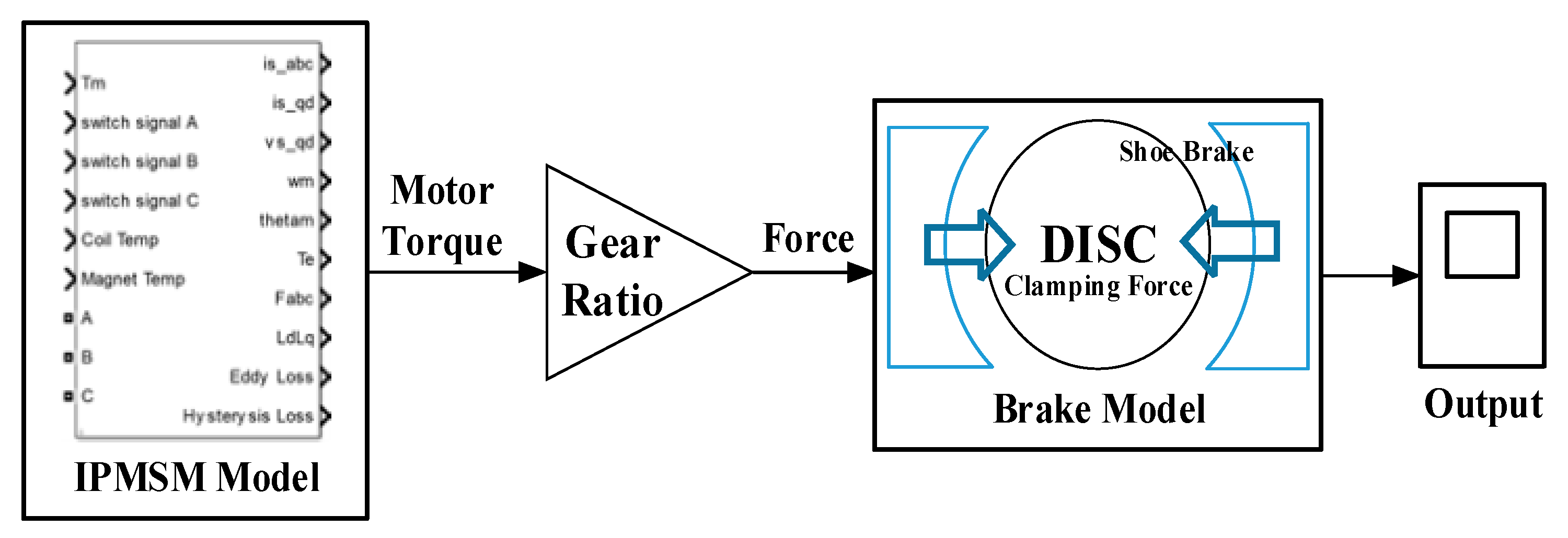
Figure 7 shows the IPMSM model and brake model for the Matlab/Simulink simulation. The IPMSM model is applied to three-phase voltage and generated output signals such as torque, stationary d–q axis current/voltage, and angular displacement.
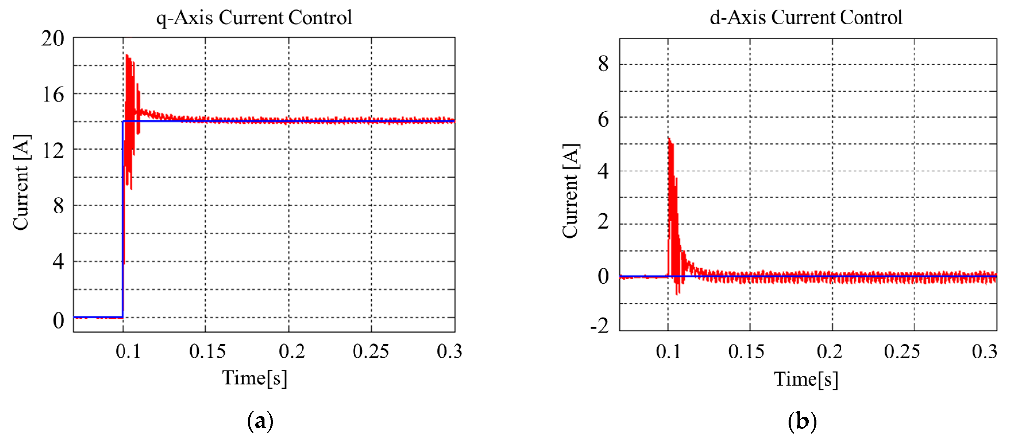
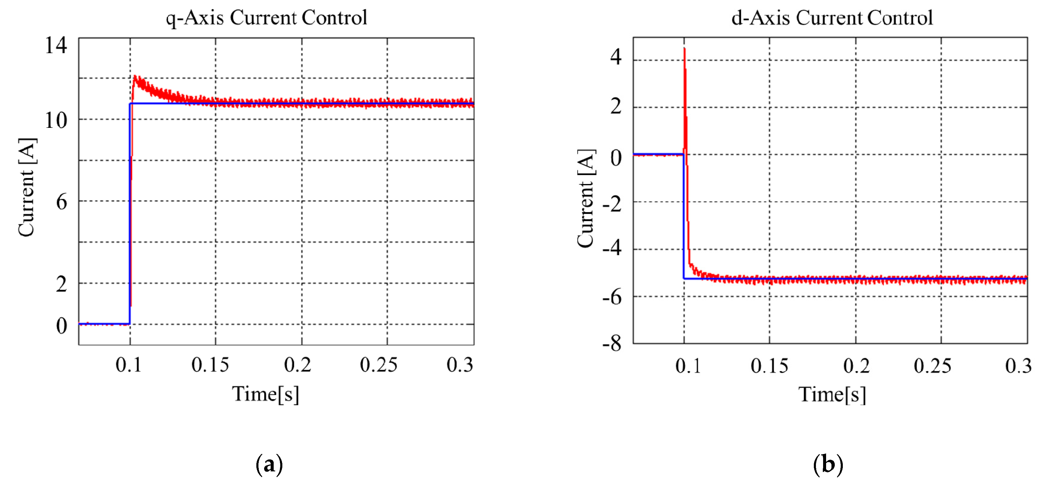
Figure 8 shows the simulation result of synchronous frame d–q axis current control without MTPA [13]. The bandwidth to calculate PI controller gain in Equation (9) is 2500 rad/s. To produce the target clamping force of ~54 kN, the d–q axis reference currents are commanded to be 0 A and 14 A, respectively. In the motor model of Figure 7, the q-axis current ripple occurred about ± 4 A and the d-axis current ripple occurred about 5 A in the transient response state. However the d–q axis current is settled within 50 ms.
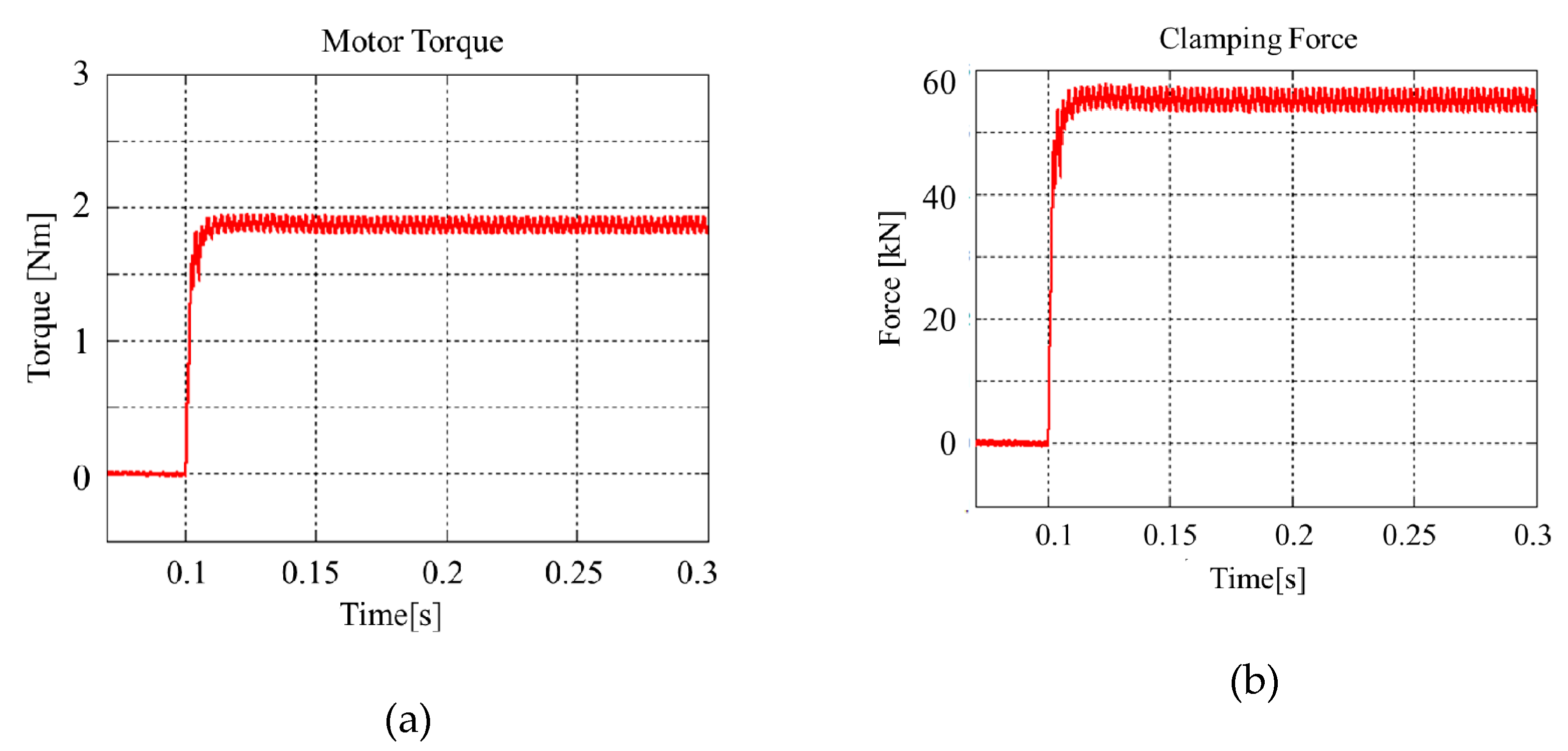
Figure 9 shows the simulation result of IPMSM torque and clamping force output with current control as shown in Figure 8. The overshoot of torque does not occur in the initial transient response and the torque ripple is ~0.15 Nm. Figure 9b shows the output of the clamping force through the reduction gear ratio and moving distance. Caliper clamping force can be calculated as follows
where, is caliper clamping force, is motor output torque, is gear ratio, and is caliper moving distance.
Figure 10 shows the simulation result of synchronous frame d–q axis current control with MTPA applied. To compare it with the current control result without MTPA, the d–q axis current control reference is commanded to be 10.77 A and −5.29 A, respectively, as shown in Table 2, and the same PI gain is applied to the current control. The d–q axis current ripple occurred at ~1.3 A and 4 A in the transient response state, respectively. As shown in Figure 8, the transient response has different types of waveform depending on the input reference current.
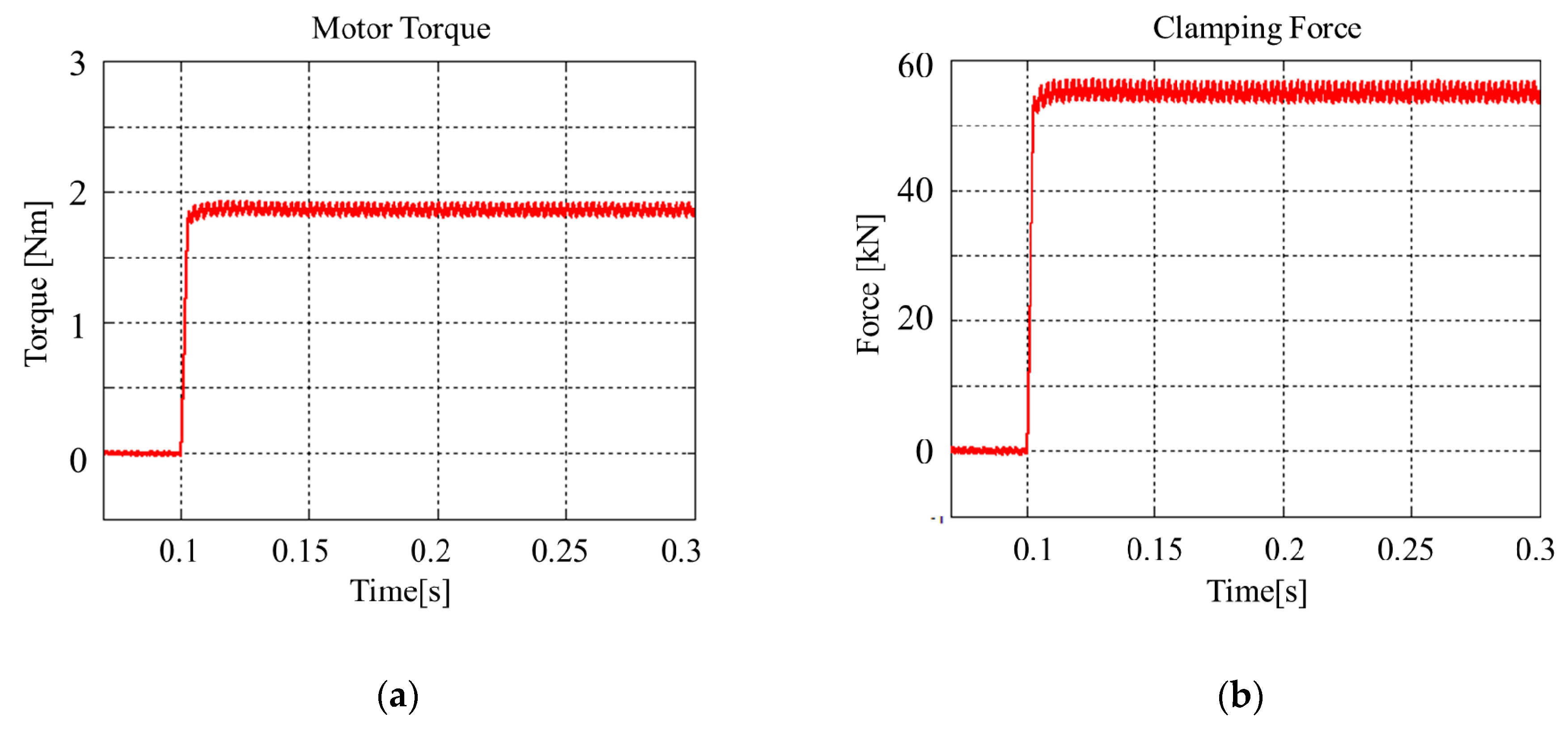
Figure 11 shows the simulation result of IPMSM torque and clamping force output according to the current control, as shown in Figure 10. Although torque output is obtained, the same value compared with Figure 9, the input current can be reduced about 2 A(14.3 %) when the MTPA control is applied.
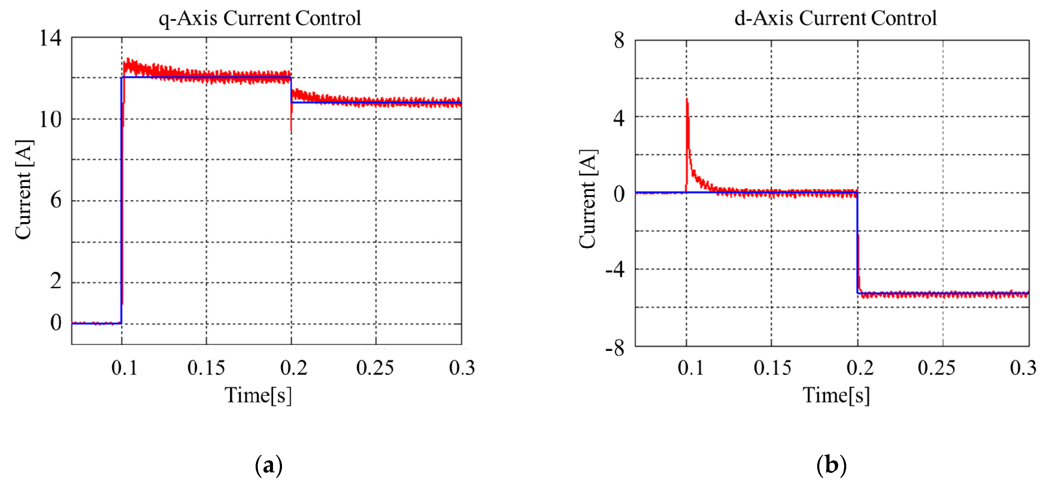
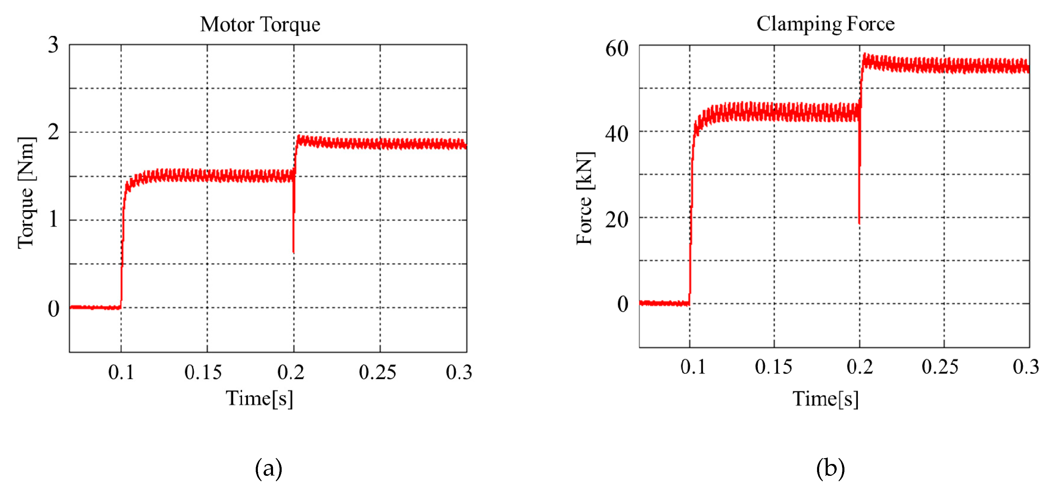
In order to compare torque changes when MTPA control is applied or not, the d axis reference current is commanded from 0A to −5.29 A at 0.2s and the q axis reference current is commanded from 12 A to 10.77 A at 0.2 s, as shown in Figure 12. The input current before and after 0.2 s is the same.
Figure 13 shows torque and clamping force results according to the current control shown in Figure 12. If d–q axis current is applied at 0 A and 12 A, respectively, IPMSM torque output is 1.5 Nm. However, when the same input current is applied with MTPA method, the IPMSM torque output is changed to 1.86 Nm and the clamping force output changes from 44.5 to 55 kN. Therefore, when the MTPA method is applied, the IPMSM torque output is improved by ~19%.
5. Experimental Results of the EMB System
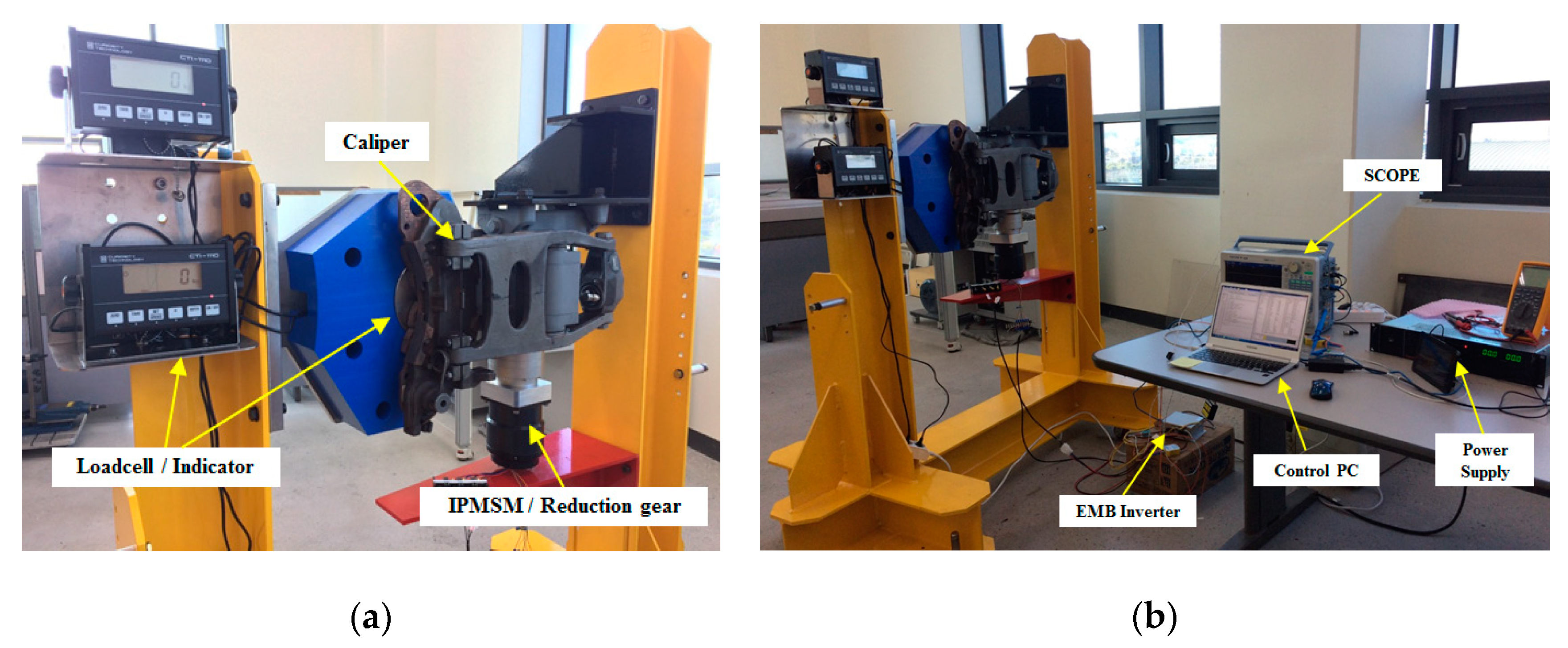
Figure 14 shows the EMB performance test rig with the same structure as a train installation. The sensor (Loadcell) is installed inside the brake disc unit to reduce the impact of caliper brake operation.
Figure 14b shows the setting to control the caliper clamping force. The microprocessor control unit (MCU) used is the TMS320F28062 and the PWM switching frequency is 10 kHz. The input voltage is applied 100 Vdc, which is the reference value of the battery voltage in the train.
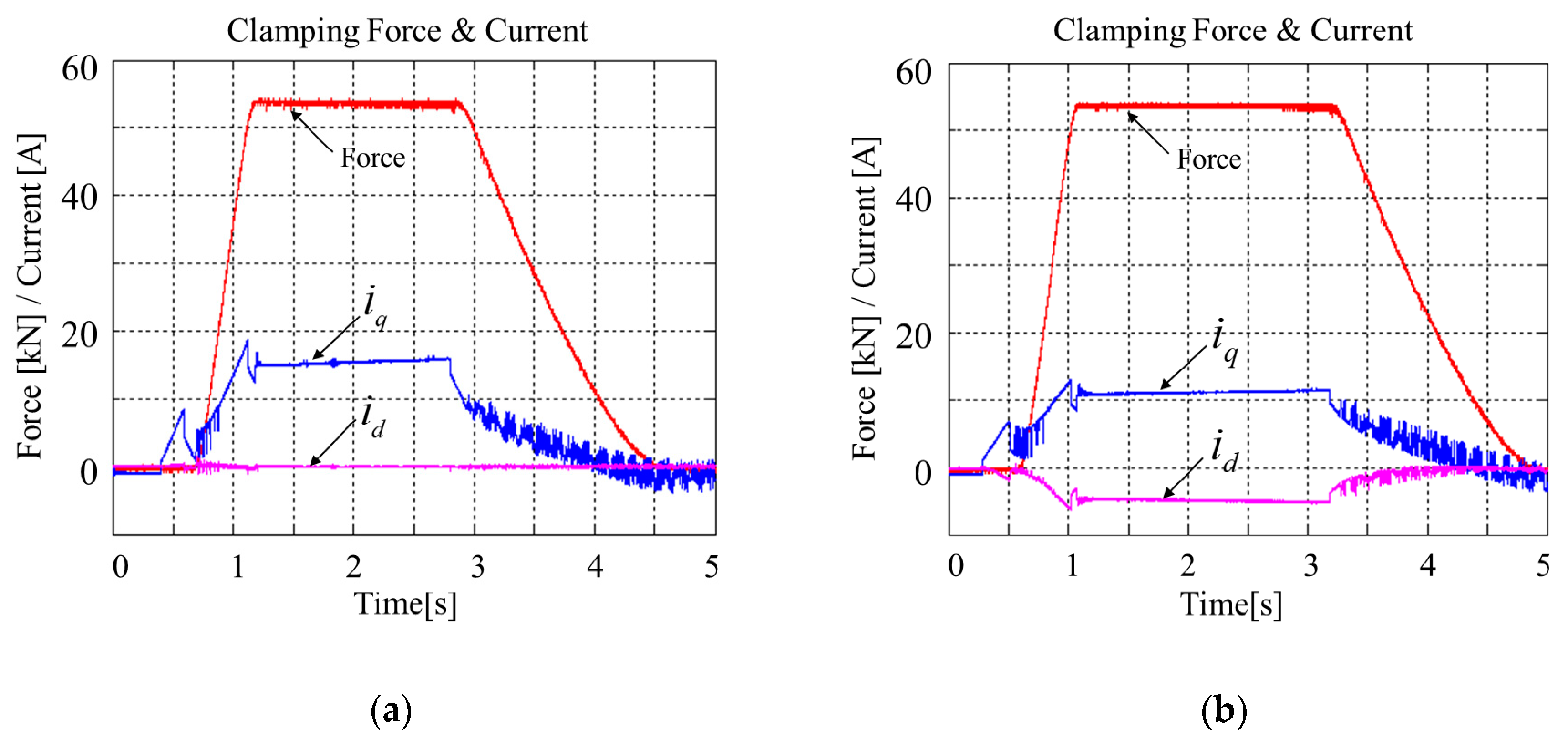
Figure 15 shows experimental results of the current controller block according to the control concept of Figure 5. The clamping force reference is 54 kN, which is the emergency brake reference of high speed train(HST) in Korea. Figure 15a shows only the q axis current and Figure 16b shows the d–q axis current commanded according to Equations (7) and (8). Two kind of control methods are satisfied for clamping force reference 54 ± 2 kN. However, when the MTPA method is not applied, input current is 15 A, and when the MTPA method is applied, input current is about 12 A.
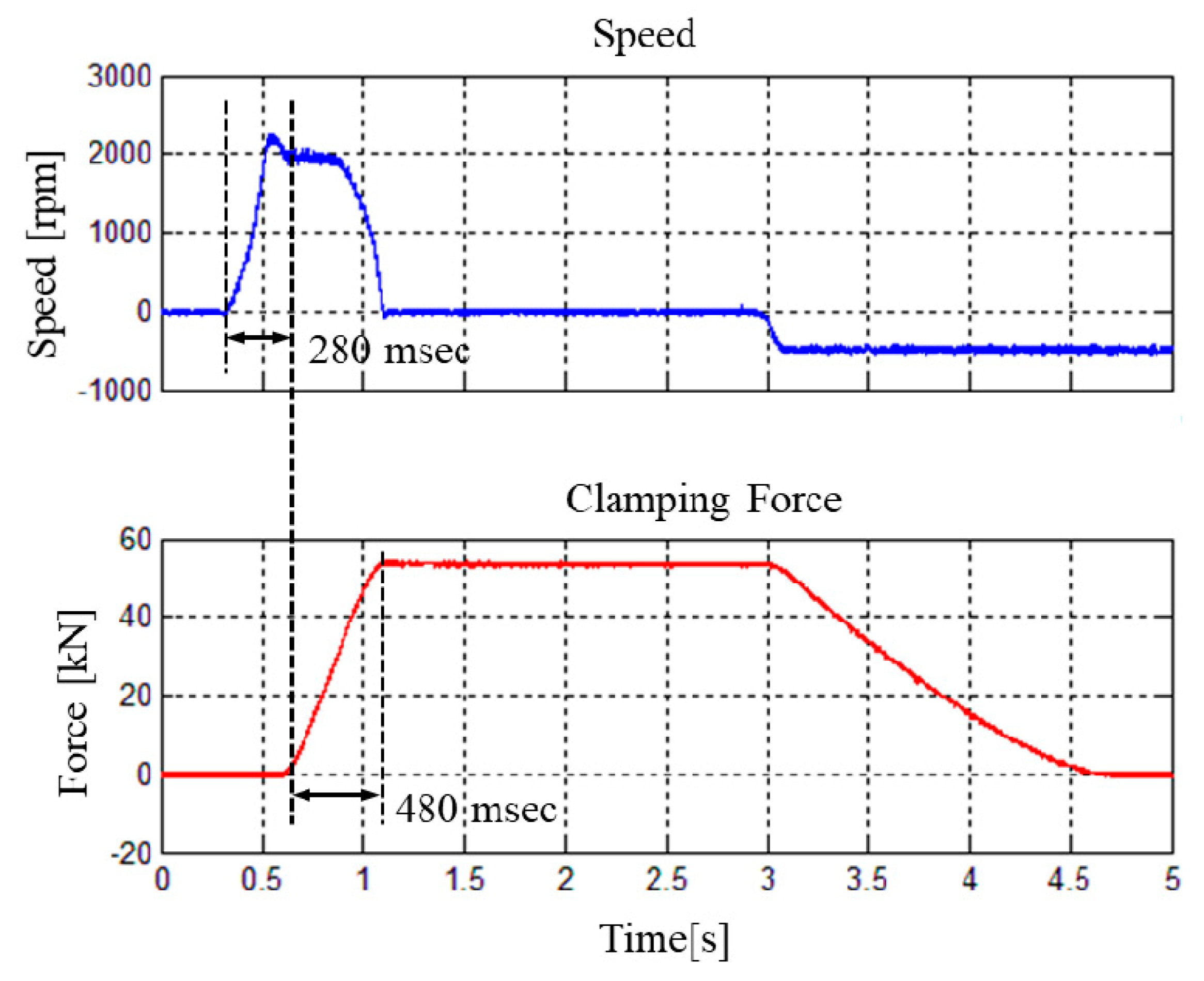
Figure 16 shows the experimental results of the speed controller block. The bandwidth to calculate the PI controller gain in Equation (9) is ~500 rad/s and inductance used the average values of and . When the EMB is braking, IPMSM is rotated within 0.28 s at a maximum speed of 2000 rpm. When the clamping force reaches 54 kN within 0.48 ms, IPMSM decelerates to 0 rpm and continues motor stall condition. The speed control result is same as whether MTPA method is applied or not.
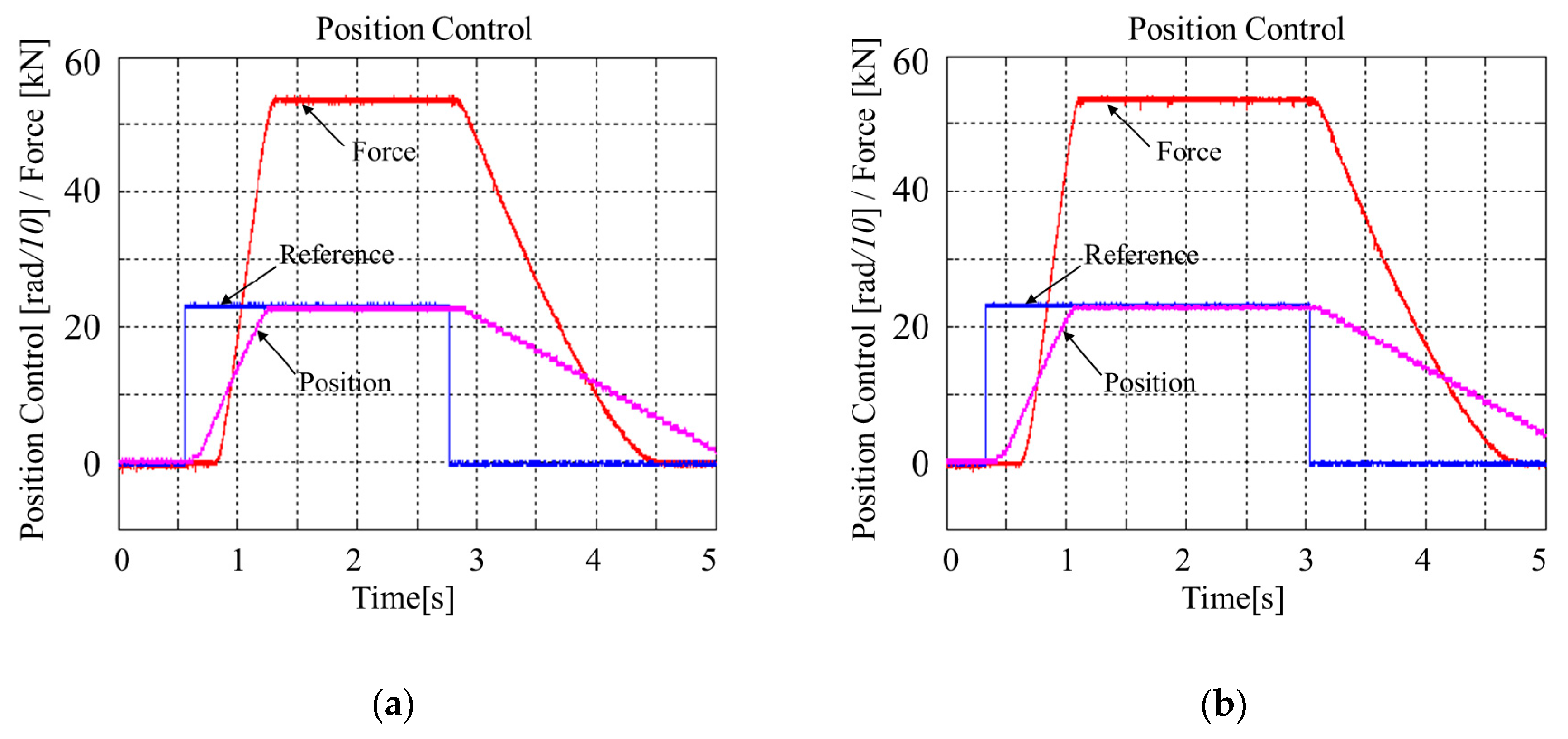
Figure 17 shows the experimental results of the position control block—the outermost controller in Figure 5. The bandwidth to calculate PI controller gain in Equation (9) is ~100 rad/s. To make the maximum clamping force of ~54 kN, the IPMSM moved ~230 radians. Regardless of whether MTPA method is applied or not, there is no difference in position control result.
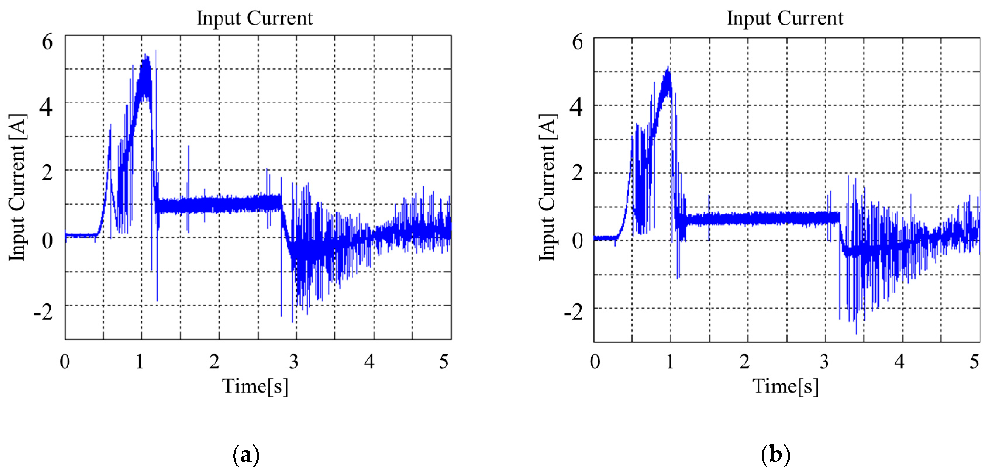
To verify the effectiveness of the MTPA control method, Figure 18 shows the DC input current waveform when the brake is activated with maximum clamping force. Maximum peak currents during the initial transient response are 5.5 A and 5 A, respectively. When the EMB reaches the motor stall condition, DC input currents are 1 A (100 W) and 0.6 A (60 W) at the maximum clamping force output, respectively. Therefore, when the MTPA scheme is applied, the EMB system reduces current consumption and the efficiency is improved ~40%.
6. Conclusions
This paper deals with efficient operation scheme for Electromechanical Brake (EMB). A current controller, speed controller, and position controller based on proportional integral control are used to drive the IPMSM. The angle , which is between the synchronous frame d–q axis currents and is calculated for MTPA control. The simulation results show that when the MTPA control is applied, the input current is reduced by 14.3% and, at the same time, the clamping force reference and clamping force are improved by 19% at the same input current. In addition, experimental results show that when the MTPA control is applied, the EMB system reduces current consumption and the total input power is reduced ~40% at the same clamping force. In future works, in order to preserve the compact, lightweight, and high reliability of the EMB system, optimal design of the EMB system is required and the losses of the driving system must be accurately measured under motor stall conditions.
Author Contributions
S.-W.K. conceived the conceptualization of this paper. J.-H.P. contributed funding acquisition. Y.-J.S. and H.-K.O. performed investigation and validation. S.-K.B. implemented the main research, performed the simulation and experiment, wrote the paper, and revised the manuscript as well. All authors have equally contributed to the simulation analysis, experiment and result discussions.
Funding
This research was supported by a grant from R&D Program (No. PK1903A1) of the Korea Railroad Research Institute, Republic of Korea.
Conflicts of Interest
The authors declare no conflict of interest.
References
- Bannatyne, R.T. Advances and challenges in electronic braking control technology. SAE Tech. Pap. 1998. [Google Scholar] [CrossRef]
- Sundar, M.; Plunkett, D. Brake-by-Wire, Motivation and Engineering-GM Sequel. SAE Tech. Pap. 2006. [Google Scholar] [CrossRef]
- Ahn, J.K.; Jung, K.H.; Kim, D.H.; Jin, H.B.; Kim, H.S.; Hwang, S.H. Analysis of a regenerative braking system for hybrid electric vehicles using an electro-mechanical brake. Int. J. Automot. Technol. 2009, 10, 229–234. [Google Scholar] [CrossRef]
- Ki, Y.H.; Lee, K.J.; Cheon, J.S.; Ahn, H.S. Design and implementation of a new clamping force estimator in electro-mechanical brake systems. Int. J. Automot. Technol. 2013, 14, 739–745. [Google Scholar] [CrossRef]
- Atia, M.R.A.; Haggag, S.A.; Kamal, A.M.M. Enhanced electromechanical brake-by-wire system using sliding mode controller. J. Dyn. Syst. Meas. Control 2016, 138, 041003. [Google Scholar] [CrossRef]
- Liang, B.; Zhu, Y.; Li, Y. Adaptive Nonsingular Fast Terminal Sliding Mode Control for Braking Systems with Electro-Mechanical Actuators Based on Radial Basis Function. Energies 2017, 10, 1637. [Google Scholar] [CrossRef]
- Jo, C.; Hwang, S.; Kim, H. Clamping-force control for electromechanical brake. IEEE Trans. Veh. Technol. 2010, 59, 3205–3212. [Google Scholar] [CrossRef]
- Lee, Y.O.; Jang, M.; Lee, W.; Lee, C.W.; Chung, C.C.; Son, Y.S. Novel clamping force control for electric parking brake systems. ELSEVIER Mechatron. 2011, 21, 1156–1162. [Google Scholar] [CrossRef]
- Eum, S.; Choi, J.; Park, S.S. Robust Clamping Force Control of an Electro-Mechanical Brake System for Application to Commercial City Buses. Energies 2017, 10, 220. [Google Scholar] [CrossRef]
- Rowan, T.M.; Kerhman, R.J. A new synchronous current regulator and an analysis of current-regulated PWM inverter. IEEE Trans. Ind. Appl. 1986, IA-22, 678–690. [Google Scholar] [CrossRef]
- Morimoto, S.; Hatanaka, K.; Tong, Y. Servo Drive System and Control Characteristics of Salient Pole Permanent Magnet Synchronous Motor. IEEE Trans. Ind. Appl. 1993, 29, 338–343. [Google Scholar] [CrossRef]
- Jahns, T.M.; Kliman, G.B.; Neumann, T.W. Interior Permanetn-Magnet Synchronous Motors for Adjustable-Speed Drives. IEEE Trans. Ind. Appl. 1986, IA-22, 738–747. [Google Scholar] [CrossRef]
- Baek, S.K.; Oh, H.K.; Kim, S.W.; Seo, S.I. A Clamping Force Performance Evaluation of the Electro Mechanical Brake Using PMSM. Energies 2018, 11, 2876. [Google Scholar] [CrossRef]
Figure 1.
Electromechanical brake (EMB) structure using the three-phase interior permanent magnet synchronous motor (IPMSM).
Figure 1.
Electromechanical brake (EMB) structure using the three-phase interior permanent magnet synchronous motor (IPMSM).

Figure 2.
Torque output of IPMSM.

Figure 3.
Torque output according to speed of IPMSM: (a) current map and (b) efficiency map.

Figure 4.
Relation of , , and for IPMSM.

Figure 5.
IPMSM control concept of EMB system.

Figure 6.
Example of d–q axis current control reference.

Figure 7.
IPMSM and brake model for Matlab/Simulink.

Figure 8.
Simulation result of current control without MTPA: (a) q-axis and (b) d-axis.

Figure 9.
Simulation result of mechanical output without maximum torque per ampere (MTPA): (a) motor torque and (b) clamping force.
Figure 9.
Simulation result of mechanical output without maximum torque per ampere (MTPA): (a) motor torque and (b) clamping force.

Figure 10.
Simulation result of current control output with MTPA: (a) q-axis and (b) d-axis.

Figure 11.
Simulation result of mechanical output with MTPA: (a) motor torque and (b) clamping force.
Figure 11.
Simulation result of mechanical output with MTPA: (a) motor torque and (b) clamping force.

Figure 12.
Input current reference between without MTPA and with MTPA: (a) q-axis and (b) d-axis.

Figure 13.
Motor torque and clamping force comparison between without MTPA and with MTPA: (a) motor torque and (b) clamping force.
Figure 13.
Motor torque and clamping force comparison between without MTPA and with MTPA: (a) motor torque and (b) clamping force.

Figure 14.
EMB performance test rig: (a) clamping force measurement and (b) EMB control setup.

Figure 15.
Experimental result of clamping force and d–q axis current control: (a) without MTPA and (b) with MTPA.
Figure 15.
Experimental result of clamping force and d–q axis current control: (a) without MTPA and (b) with MTPA.

Figure 16.
Experimental result of speed control.

Figure 17.
Experimental result of position control: (a) without MTPA and (b) with MTPA.

Figure 18.
Experimental result of input current: (a) without MTPA and (b) with MTPA.


Table 1.
IPMSM specifications.
| Motor Specification | |
|---|---|
| Output Power | 1000 W |
| Rated Speed | 3000 rpm |
| Resistance | 0.19492 Ω |
| Inductance | 2.8 mH |
| Inductance | 5.4 mH |
| Rated Current | 15 A |
| Rated Torque | 3.2 Nm |
| Number of Phase | 3 |
| Input Voltage | 100 V |
Table 2.
Maximum torque points according to the input stator current .
| (deg) | |||
|---|---|---|---|
| 5 | −1.30 | 4.84 | 105.0 |
| 7 | −2.31 | 6.61 | 109.3 |
| 10 | −4.05 | 9.14 | 113.9 |
| 12 | −5.29 | 10.77 | 116.2 |
| 14 | −6.58 | 12.36 | 118.0 |
| 16 | −7.90 | 13.91 | 119.6 |
| 18 | −9.23 | 15.45 | 120.9 |
| 20 | −10.59 | 16.97 | 122.0 |
© 2019 by the authors. Licensee MDPI, Basel, Switzerland. This article is an open access article distributed under the terms and conditions of the Creative Commons Attribution (CC BY) license (http://creativecommons.org/licenses/by/4.0/).
Share and Cite
MDPI and ACS Style
Baek, S.-K.; Oh, H.-K.; Park, J.-H.; Shin, Y.-J.; Kim, S.-W. Evaluation of Efficient Operation for Electromechanical Brake Using Maximum Torque per Ampere Control. Energies 2019, 12, 1869. https://doi.org/10.3390/en12101869
AMA Style
Baek S-K, Oh H-K, Park J-H, Shin Y-J, Kim S-W. Evaluation of Efficient Operation for Electromechanical Brake Using Maximum Torque per Ampere Control. Energies. 2019; 12(10):1869. https://doi.org/10.3390/en12101869
Chicago/Turabian StyleBaek, Seung-Koo, Hyuck-Keun Oh, Joon-Hyuk Park, Yu-Jeong Shin, and Seog-Won Kim. 2019. "Evaluation of Efficient Operation for Electromechanical Brake Using Maximum Torque per Ampere Control" Energies 12, no. 10: 1869. https://doi.org/10.3390/en12101869
Note that from the first issue of 2016, this journal uses article numbers instead of page numbers. See further details here.