A Compensation Control Scheme of Voltage Unbalance Using a Combined Three-Phase Inverter in an Islanded Microgrid


Department of Electronical Engineering, Xi’an University of Technology, Xi’an 710048, China
*
Author to whom correspondence should be addressed.
Energies 2018, 11(9), 2486; https://doi.org/10.3390/en11092486
Submission received: 14 August 2018
/
Revised: 16 September 2018
/
Accepted: 17 September 2018
/
Published: 18 September 2018
Abstract
:A large number of single-phase loads in an islanded microgrid have a bad influence on the alternating current (AC) bus voltage symmetry, which will further impact the power supply for the other loads. In this paper, the combined three-phase inverter is adopted as the distributed generation (DG) interface circuit for its independent control of each bridge. However, the combined three-phase inverter will generate an asymmetrical voltage with the traditional droop control. Moreover, the system impedance also effects the voltage symmetry. Therefore, the improved droop control method based on the self-adjusting P-f and Q-U droop curves and the system impedance voltage drop compensation are proposed. The system control scheme is also designed in detail. A simulation and an experiment under the conditions of the balanced, unbalanced loads are carried out, and the results verify the feasibility and effectiveness of the control strategy.
1. Introduction
In recent years, the development of the microgrid has attracted great attention in various countries across the world. A microgrid is a controllable system which is composed of multiple distributed generations (DGs), local loads, energy storage devices, and monitoring protection devices [1,2]. The system reliability increases when the intermittent renewable energies are combined with the storage devices in a microgrid with hybrid inverter-interfaced DG system [3]. The microgrid can operate not only in the grid-connected mode, but also in the islanded mode, providing more reliable power to critical loads [4,5]. In the islanded microgrid, most studies focus on parallel-inverter power sharing [6,7] and circulation restraint [8], power management for all kinds of DGs and types of energy storage [9,10], and compensation for voltage unbalance [3,11,12,13,14,15,16,17,18].
In the islanded mode, there are many single-phase and three-phase loads, and they lack voltage and frequency support from the power grid, so that the unbalanced loads will result in asymmetrical three-phase voltages. As a result, the power system may become less stable and the negative-sequence voltage components will exert bad impacts on the equipment, such as the transformer and induction motor. There are some works based on dynamic hybrid DG operation, and power system stability in faults [4,19,20]. Under a serious condition, when the microgrid distribution systems are under fault, the system becomes unstable. In [19], an asymmetrical faults analysis with hybrid compensation is proposed. When serious unbalanced faults occur, the stability and voltage compensation of the system can be realized by the static synchronous compensator (STATCOM) to effectively stabilize the network under unstable conditions [4]. In [20], the voltage and current unbalance definition is completed. The international electrotechnical commission (IEC) requires that the voltage unbalance should be maintained within 2% in electric systems.
On the other hand, voltage unbalance is caused by unbalanced loads. In order to solve the voltage problem, active power filters (APFs) are utilized to compensate for voltage unbalance [11]. However, under low voltages and in small-capacity microgrids, installation of the extra APF will bring high costs. Generally, the voltage unbalance compensation can be realized by the DG unit inverter itself when the DG capacity is within the compensation capacity range. In general, the circuit topology and its corresponding control strategy are key factors to solving the problem of three-phase voltage asymmetry. The most popular circuit topologies include the three-phase three-wire inverter, the three-phase four-leg inverter, and the combined three-phase inverter. For the three-phase three-wire inverter, a negative-sequence impedance controller with droop control is employed to effectively compensate for the negative-sequence currents of the unbalanced loads, and to regulate the load voltage and share the average power components among the DG units [12,13,14]. In [13], the central secondary controller is designed to manage the compensation of voltage unbalance and send the proper control signals to the local controllers. However, the DG units need an extra communication line to obtain the compensation signals from the central controller. In [14], the compensation of the voltage unbalance can be achieved by reducing the negative-sequence voltage to generate this compensation reference. However, the extraction of positive- and negative sequence components brings the complex calculation. The virtual impedance loop is modified to improve the compensation effect [15], which introduces the problem of voltage drop and performance degradation of voltage quality caused by the virtual impedance.
As for the three-phase four-bridge inverter, the front three bridge legs are used to adjust the positive- and negative-sequence voltages, and the fourth bridge leg is utilized to regulate the zero-sequence output voltage on the basis of the symmetrical component method [16,17,18]. For a three-phase four-leg inverter, the above methods need Clarke transformation, which is used to transform the variables of voltage and current between the abc and αβ frame. The extraction of positive- and negative- and zero-sequence components is necessary; the fundamental positive sequence active and reactive powers are needed for decoupling, and the system control algorithm is complex. Moreover, the unbalanced voltage drop across the system impedance is not considered, which leads to degraded performance by the output voltage.
The combined three-phase inverter consists of three same single-phase full-bridge inverters. This topology has the advantage of power decouple and the independent control of each bridge, and no complex extraction of positive- and negative- and zero-sequence components. Therefore, the combined three-phase inverter is chosen as the interface circuit to connect with the common AC bus in this paper. However, the independent droop control of each bridge will give rise to the reference voltage asymmetric, which will in further cause the AC bus voltage unbalanced. Hence, it is necessary to design a reasonable control strategy to supply the symmetry voltage for the islanded microgrid.
The original contributions of this paper are concluded as follows: (1) The combined three-phase inverter is adopted as the DG interface circuit to improve the voltage balance in a low voltage microgrid; (2) in order to obtain the symmetrical reference voltage, an improved droop control based on self-adjusting Q-U and P-f curves is proposed; (3) the influence of system impedance on the load voltage symmetry is analyzed in detail, and impedance voltage drop compensation is added to the symmetrical reference voltage to suppress the impact of system impedances on the voltage symmetry. Eventually, combining the improved droop control with the impedance voltage drop compensation control, it is confirmed to be right and feasible by the simulation and experimental results.
This structure of this paper is organized as follows. In the second section, the cause of the voltage unbalance with conventional droop control is analyzed. The symmetrical control strategy is analyzed in detail in the third section. The fourth section shows the simulation and experimental analysis. The conclusion is drawn in the last section.
2. Cause of Voltage Unbalance with Conventional Droop Control
2.1. Circuit Configuration and Operating Principle
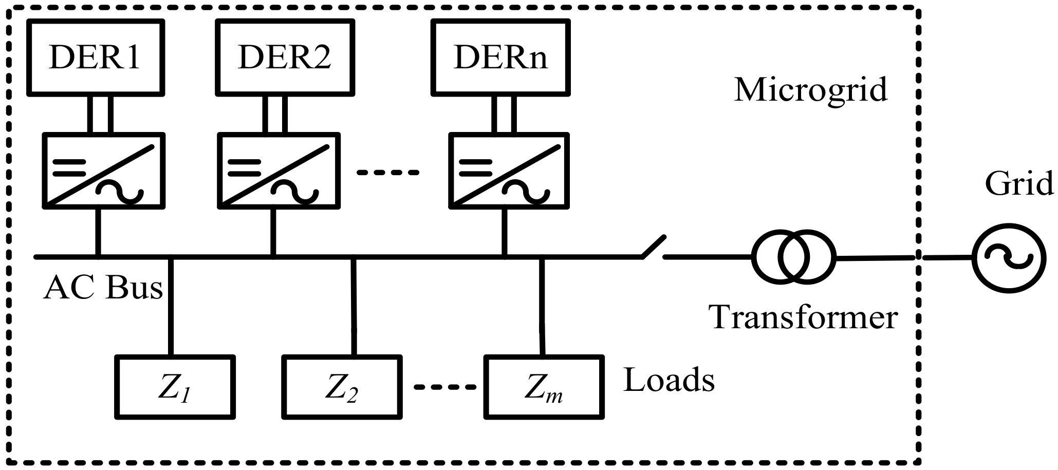
Figure 1 shows the simplified microgrid structure, which consists of multiple inverter-interfaced distributed energy sources (DERs) and local loads. The microgrid connects the grid by the step-up transformer.
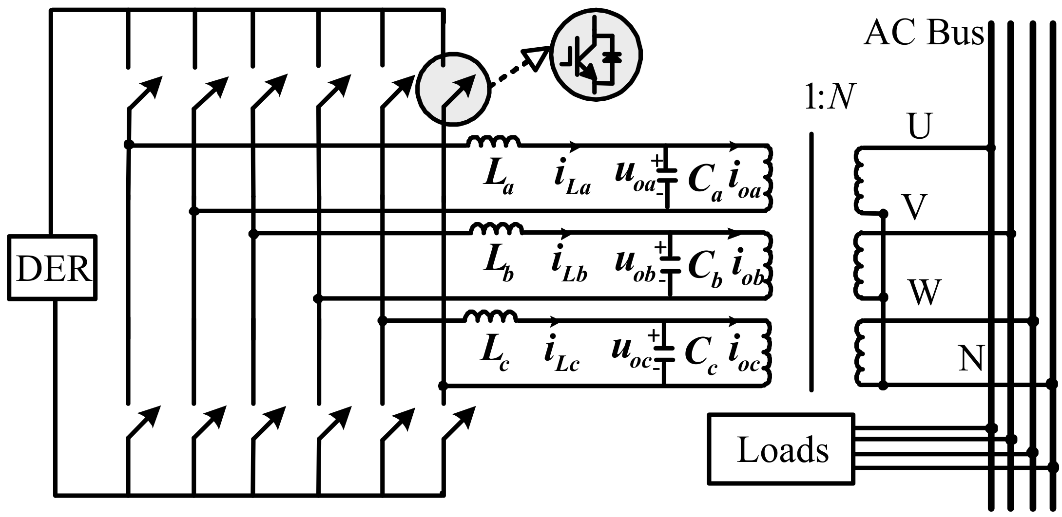
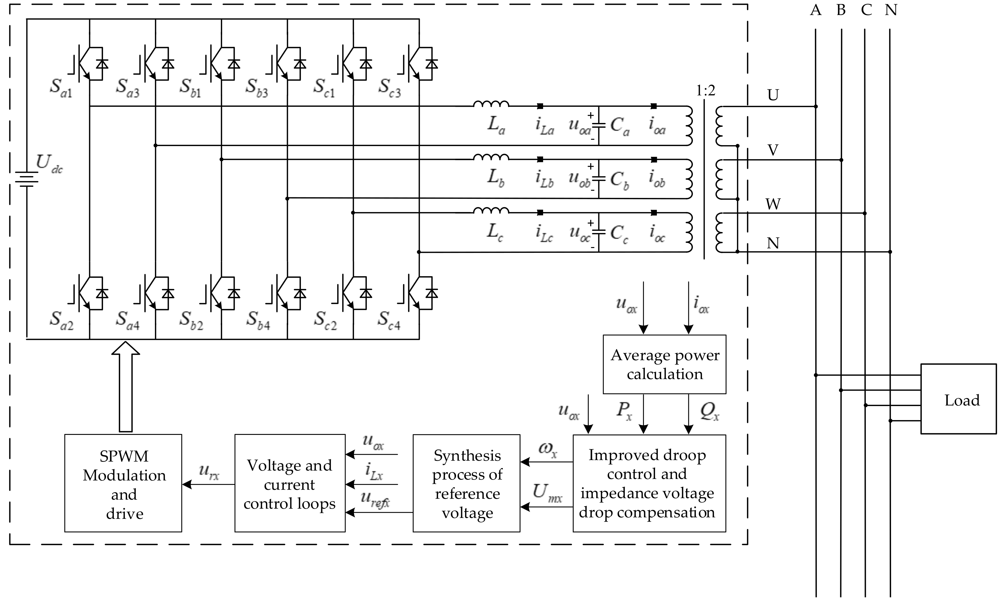
The combined three-phase inverter has good performance, with independent and flexible control and simple structure [21]. In this paper, this inverter was chosen as the DG interface circuit, which is shown in Figure 2. The three-phase combined inverter is comprised of three-phase H-bridge inverters connecting with a common AC bus. The output terminals of each H-bridge inverter were connected with a single-phase transformer for the required isolation and voltage boost.
When disconnected from the grid, the microgrid operates in the islanding mode. The parallel inverters should supply the quality voltage for loads, and they are usually controlled by the droop controller to achieve power sharing. The traditional active power-frequency (P-f) and reactive power-voltage (Q-U) droop control is used, which can be expressed by Equation (1) [22,23]:
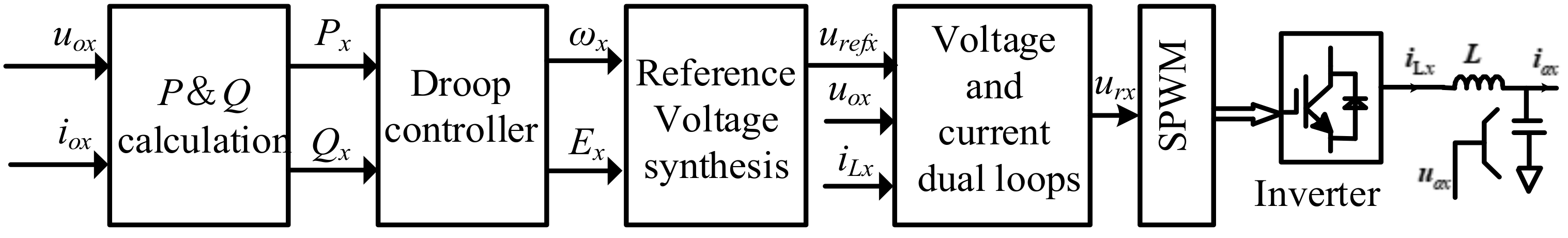
Along with the droop characteristics, the general block diagram of the control scheme for parallel inverters is shown in Figure 3.
In Figure 3, the average active power Px (x = a, b, c) and reactive power are calculated from the inverter output voltage uox and current . By using (1), the angle frequency ωx and amplitude Ex are evaluated from Px and Qx. ωx and Ex are synthesized to obtain the reference voltage urefx of the voltage controller. Finally, the modulation wave urx is obtained through the voltage and current dual loops and they are compared with the triangular carrier modulator signal, and then a sinusoidal pulse width modulation (SPWM) signal is obtained and amplified to drive the operation of the combined three-phase inverter.
Under the condition of balanced loads, the three-phase reference voltage frequencies/amplitudes based on the P-f/Q-U droop control are consistent. However, three-phase inverter output powers are different under the condition of unbalanced loads so that the independent droop control of each bridge will give rise to the asymmetric reference voltage, which will cause the unbalanced AC bus voltage.
2.2. Influence of Unbalanced Loads and System Impedances on Voltage Symmetry
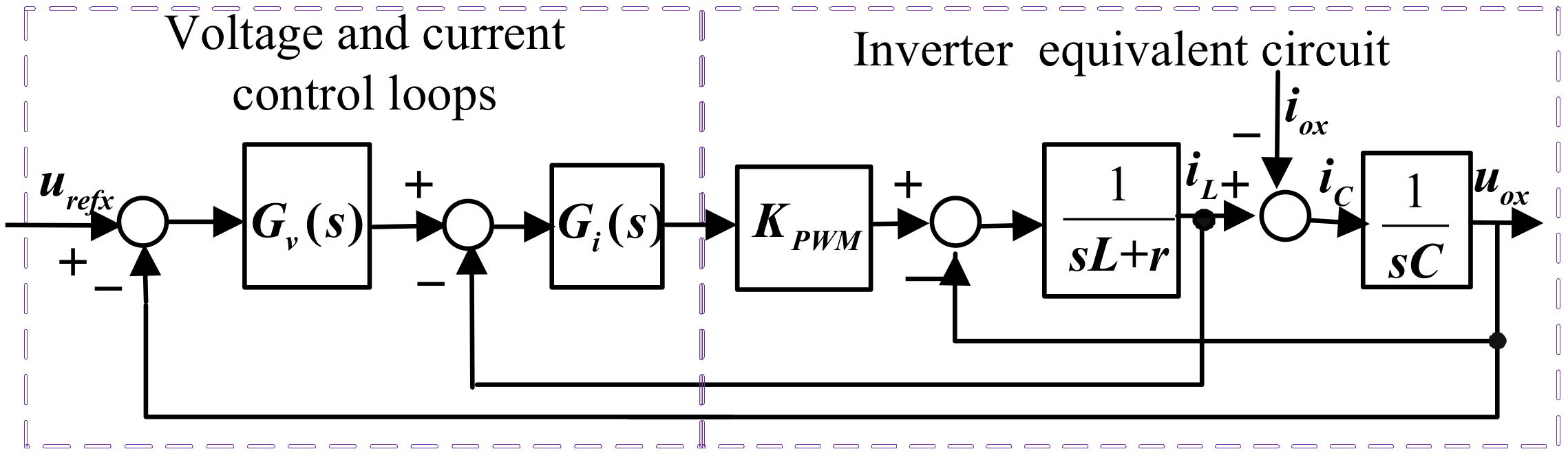
The block diagram of the voltage and current control loops are shown in Figure 4. L and C are inverter filter parameters, and r is the sum of parasitic resistance of the filter inductor and the equivalent resistance caused by the system dead zone. Gv(s) and Gi(s) are the voltage and current controller, respectively. Kpwm is the gain of the pulse width modulation. From Figure 4, the relationship between the three-phase output voltage uox and the three-phase reference voltage urefx can be expressed by (2) [13]:
In (2), Gx(s) is the gain of the system closed-loop transfer function, and Zox(s) is the system each-phase output impedance. They can be described by (3) and (4) respectively:
Based on (2), the output voltage symmetry is dependent on reference voltage urefx and inverter output impedance Zox. There are two influential factors in the output voltage symmetry, one of which is reference voltage urefx, which can be obtained by the synthesis of angle frequency ωx and amplitude Ex. Based on traditional droop control Equation (1), when three-phase loads become unbalanced, both Px and Qx for each phase are unequal. Therefore, ωx and Ex of each phase are inconsistent; that is, the reference voltages urefx of the three-phase inverter are inconsistent, which will lead to an asymmetrical load voltage. Hence, the traditional droop control cannot guarantee the symmetry of the three-phase reference voltages urefx for the combined three-phase inverter. The other factor is the system impedance Zox. Even if the three-phase reference voltage urefx is symmetrical, the output voltage uox may still be asymmetrical because Zox can be neglected, and the output current iox will have a certain voltage drop on the system impedance Zox.
3. Symmetrical Control Strategy of Three-Phase Voltages
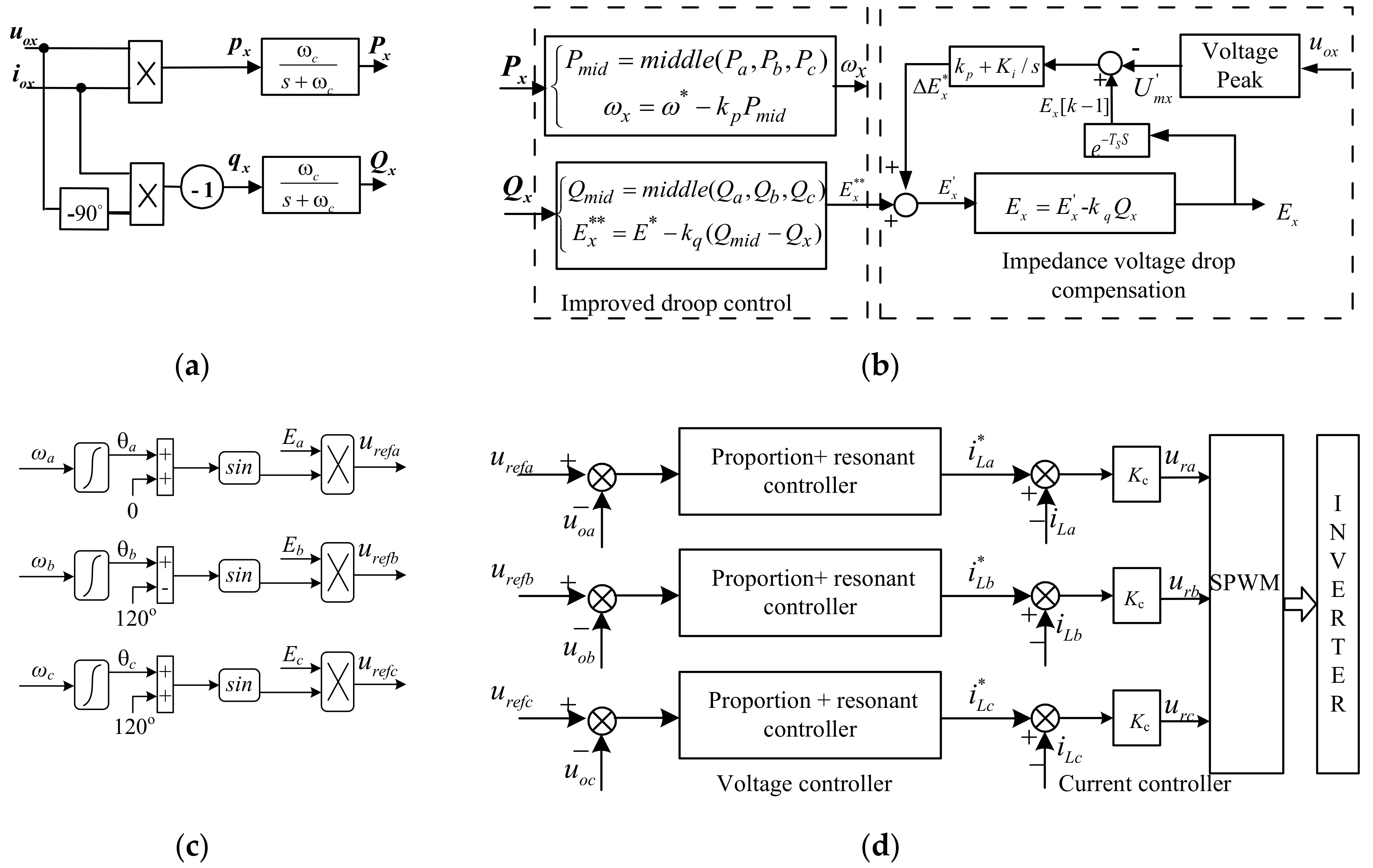
Figure 5 is the main circuit of the inverter system and its control scheme. The control scheme includes four parts; namely, the average power calculation, improved droop control, and impedance voltage drop compensation, reference voltage synthesis, and voltage and current controller. The detailed implementation of the control scheme is shown in Figure 6. Figure 7 is a flowchart for the description of the designed control scheme.
3.1. Calculation of Average Power
In Figure 6a, the inverter each-phase output voltages uox (x = a, b, c) and output currents are sampled respectively, and then the instantaneous active power px and reactive power qx are obtained by (5). The −90° phase shift in is required, and px, qx are filtered by low-pass filters (LPFs) to achieve the average active power Px and reactive power . The LPF is given by (6), where the cutoff angle frequency ωc is set to 314 rad/s.
3.2. Improved Droop Control Strategy and Impedance Voltage Drop Compensation
In Figure 6b, the improved droop controller based on the self-adjustment P-f droop curve can generate the equal angle frequency ωx and the self-adjustment Q-U droop curve can generate the new no-load voltage amplitude E**, which can ensure symmetrical reference voltage. Meanwhile, in view of the each-phase impedance voltage drop on the system impedance, the impedance voltage drop compensation ΔEx* is added to the no-load voltage amplitude , and the new no-load voltage can be acquired. Finally, the reference voltage amplitude Ex is regulated again with the Q-U droop control.
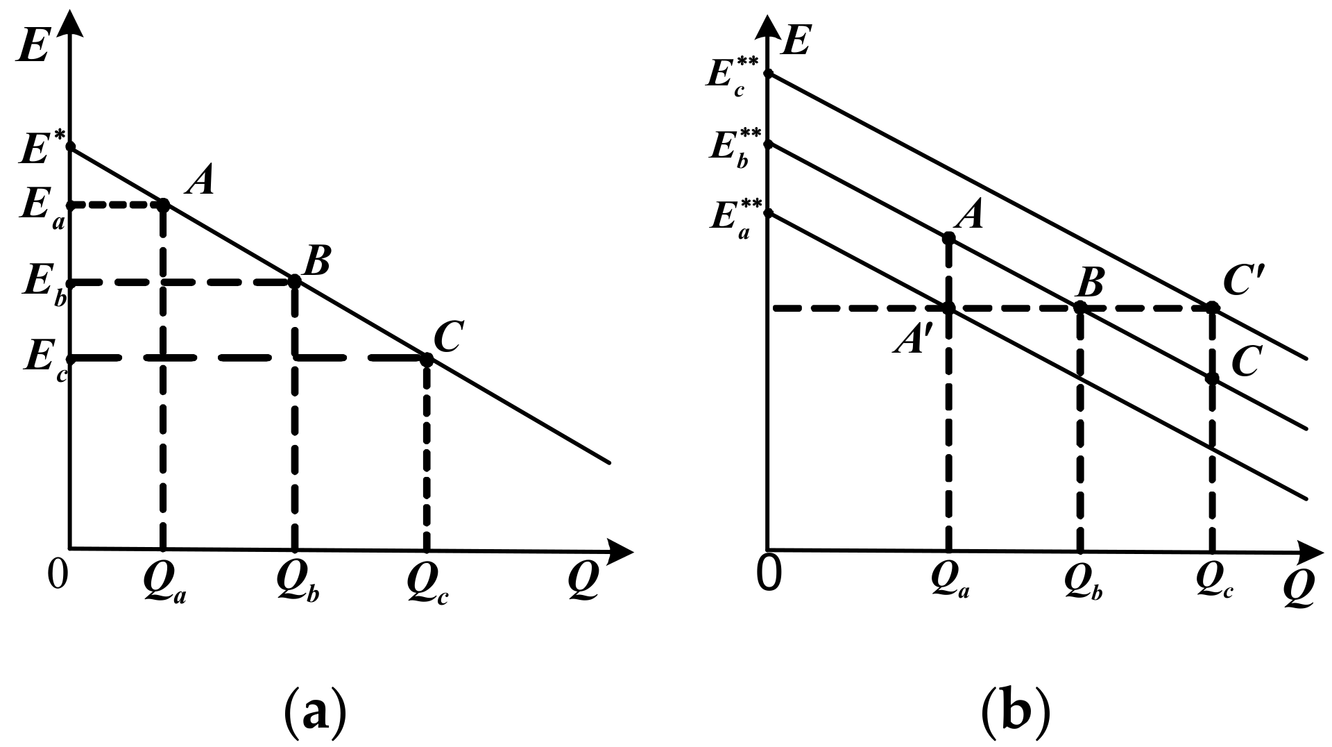
In Figure 8a, when three-phase reactive powers are different (for example, Qa < Qb < Qc), the phase inverters are working at points A, B, C respectively, and the amplitudes of the three-phase reference voltage are Ea, Eb, Ec, respectively, which can cause the asymmetrical three-phase output voltage. To solve this problem, a self-adjustment Q-U droop control strategy is proposed in Figure 7b. Three-phase load reactive powers are compared with each other, and then the middle output reactive power Qmid can be obtained (for example, Qmid = Qb). What is more, the other phases take the same droop coefficient, and the no-load point voltage is calculated using (7) to ensure that the voltage amplitudes for each phase are equal:
where (x = a, b, c) is the each-phase-adjusted voltage amplitude at no load with improved droop control, where middle function middle(Qa, Qb, Qc) means taking the intermediate value among the three-phase powers. The original operating points A and C shift to points A′ and C′. This means that the amplitudes of three-phase reference voltage are always equal, which can ensure that the three-phase reference voltage amplitudes are equal. The reference voltage amplitude Ex can be obtained by bringing the adjusted voltage amplitude at no load into (1), which can be deduced by (8), and it can ensure that the three-phase reference voltage amplitudes Ex for each phase are always equal, which can achieve the same three-phase reference voltage amplitude.
Figure 8b shows the self-adjustment Q-U droop curves based on (7). The original operating points A and C shift to points A′ and C′. Thus, the amplitudes of three-phase reference voltage are equal.
In order to avoid the output voltage amplitude exceeding the voltage operation range by the adjustment of the no-load voltage on the droop curve for each phase, the choice of the output voltage amplitude of the middle output power as a reference for the other phases should be reasonable. The output voltage amplitude for the heavy load is comparatively low, and the increment on the no-load voltage can raise the output voltage. Similarly, the output voltage amplitude for the light load is high, so that the reduction on the no-load voltage can reduce the output voltage. In addition, the droop coefficient is always unchangeable, and the load power can be shared for the parallel inverters.
Similarly, unbalanced three-phase loads can lead to the unequal three-phase frequencies. Therefore, in this paper, the P-f droop control curve is described as (9), where Pmid is the intermediate value among the three-phase active powers:
By (7) and (9), the symmetrical reference voltage can be derived. However, the inverter each-phase system impedance can bring about a non-negligible voltage drop, which will cause output voltage asymmetry. To reduce the influence of the each-phase impedance voltage drop on the voltage balance, the impedance voltage drop compensation component is added with the no-load voltage by the improved droop controller output, which is shown in Figure 6b. Each phase output voltage uox is sampled to acquire the peak value of output voltage . The difference between reference voltage amplitude Ex and can reveal the voltage drop on each phase impedance. The error between the last beat for the reference voltage amplitude and is regulated by the proportional-integral controller to obtain the no-load voltage amplitude regulator compensation , which is expressed by (10), where Ts is the sampling time. The no-load voltage on the improved droop control is added with to obtain the new no-load voltage amplitude , which can be revised by (11). Finally, the amplitude of the reference voltage Ex is adjusted by the droop control (12) to further improve the unbalanced degree of the three-phase output voltage.
3.3. Reference Voltage Synthesis
The angle frequency ωx and amplitude Ex are synthesized to obtain the reference voltage urefx of the voltage controller. The synthesis process is demonstrated in Figure 6c, where the angle frequency ωx is integrated to generate the phase angle θx.
3.4. The Voltage and Current Controller
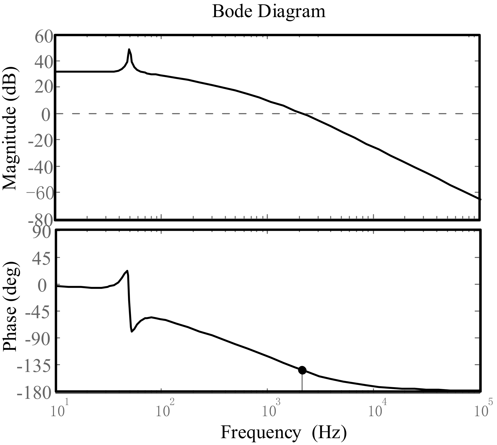
Figure 6d shows the block diagram of the voltage and current control loops. In order to enhance the current dynamic respond, the current controller adopts proportion regulator with a filter inductor current as the feedback signal. The proportional coefficient kc can be acquired by (13), where L is the filter inductor. In the voltage control loop, the filter capacitor voltage is used as the feedback signal, and the quasi proportion and resonant (QPR) controller is adopted which can enhance the gain at resonant angle frequency ωo and deliver good voltage performance. The transfer function Gv(s) is described by (14) [24], where kvp and kr are the proportion coefficient and the resonant coefficient, and ωh is the resonant bandwidth and is set to 5 rad/s. The coefficients kvp and kr are designed based on the system stability. Based on Figure 4, the system open-loop transfer function can be described by (15). Figure 9 shows the Bode plots of the system open-loop transfer function in light of (15). It is known that the system is stabile due to a high magnitude margin and phase margin:
4. Simulation and Experimental Verification
4.1. Simulation Verification
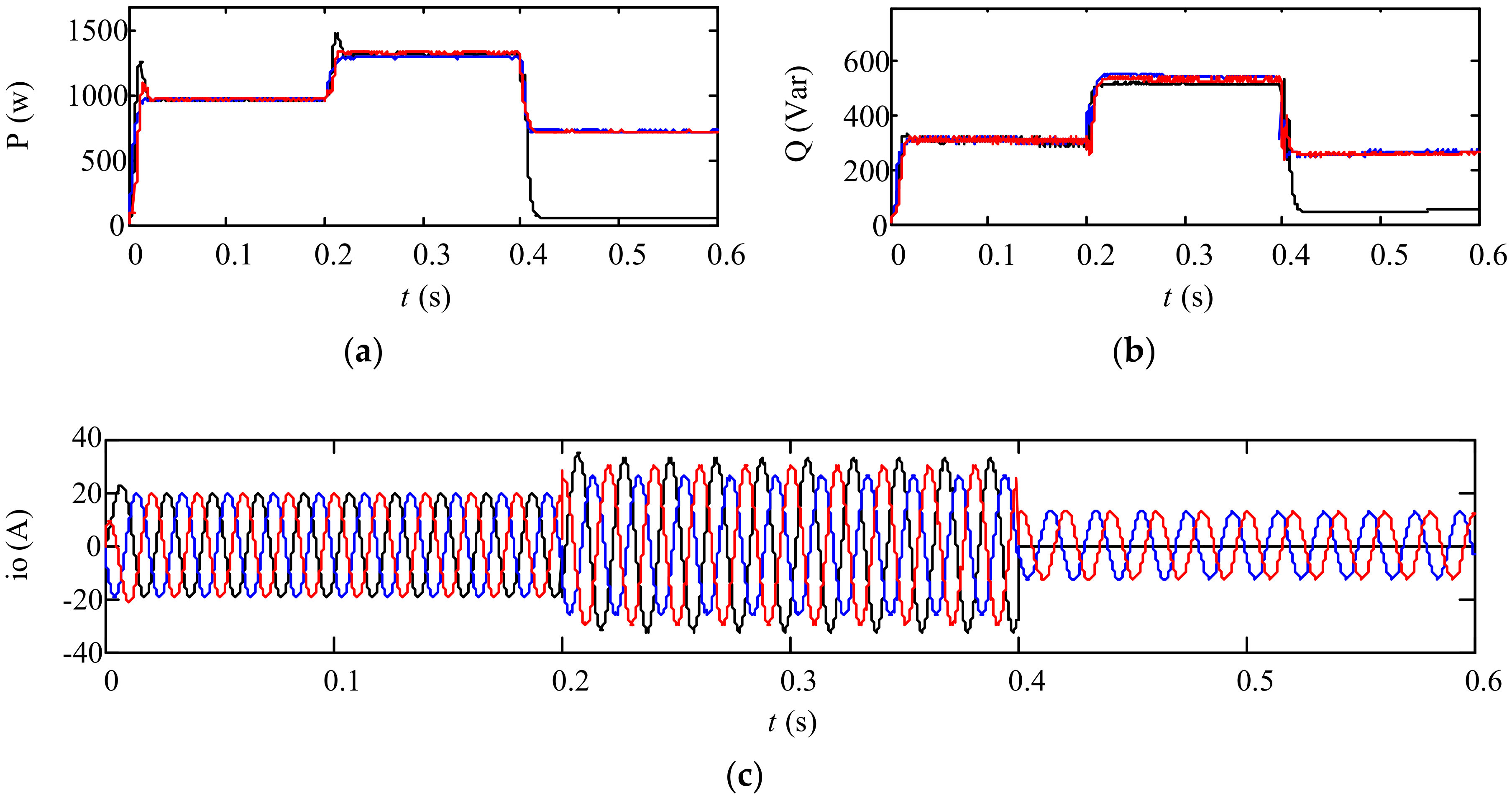
Figure 10 shows the three-phase load active powers, reactive powers, and load currents under various load conditions. In Figure 10, the three-phase loads condition is given as follows. During 0~0.2 s, three-phase loads are balanced. During 0.2~0.4 s, three-phase loads are slightly unbalanced. During 0.4~0.6 s, the three-phase loads become extremely unbalanced.
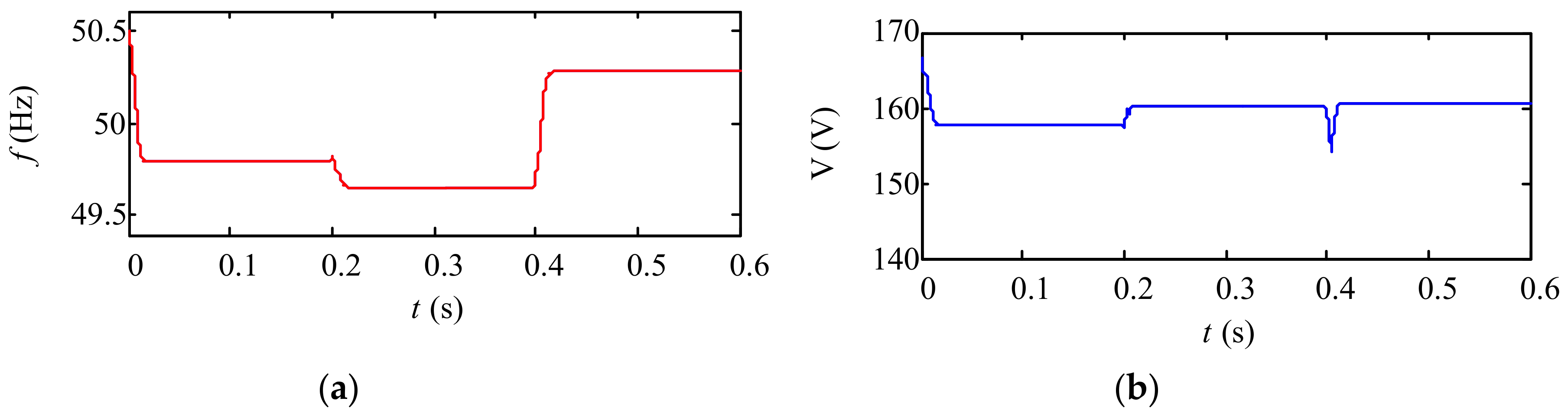
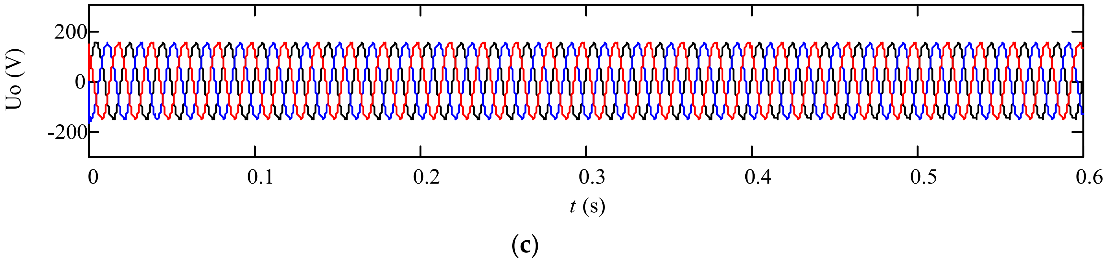
Under these conditions, Figure 11 and Figure 12 show the voltage waveforms with the traditional droop control and the proposed control method respectively.
In Figure 11, it can be shown that before 0.2 s, the system three-phase reference voltage amplitudes are consistent and the corresponding frequencies are the same too. Thus, the inverter output voltages are balanced when three-phase load powers are balanced. However, during 0.2~0.4 s, three-phase reference voltage amplitudes become inconsistent and the frequencies are also different. Hence, the inverter output voltage is unbalanced with the traditional droop control under the condition of unbalanced load. During 0.4~0.6 s, under the severe condition that one phase is no load, the unbalance degree of the output voltage is high. Therefore, it can be seen that the traditional droop control cannot ensure the voltage balance under various load conditions.
In Figure 12, with the proposed control method, the three-phase frequencies are adjusted to be equal, and the amplitudes are consistent too. Thus, the output voltage is balanced even under the serious unbalanced condition.
4.2. Experimental Verification
The experimental platform of the inverter with a rated active power PN = 1 kW is built. The system parameters and control parameters are listed in Table 1. The experimental results are shown in Figure 13, Figure 14, Figure 15, Figure 16, Figure 17 and Figure 18.
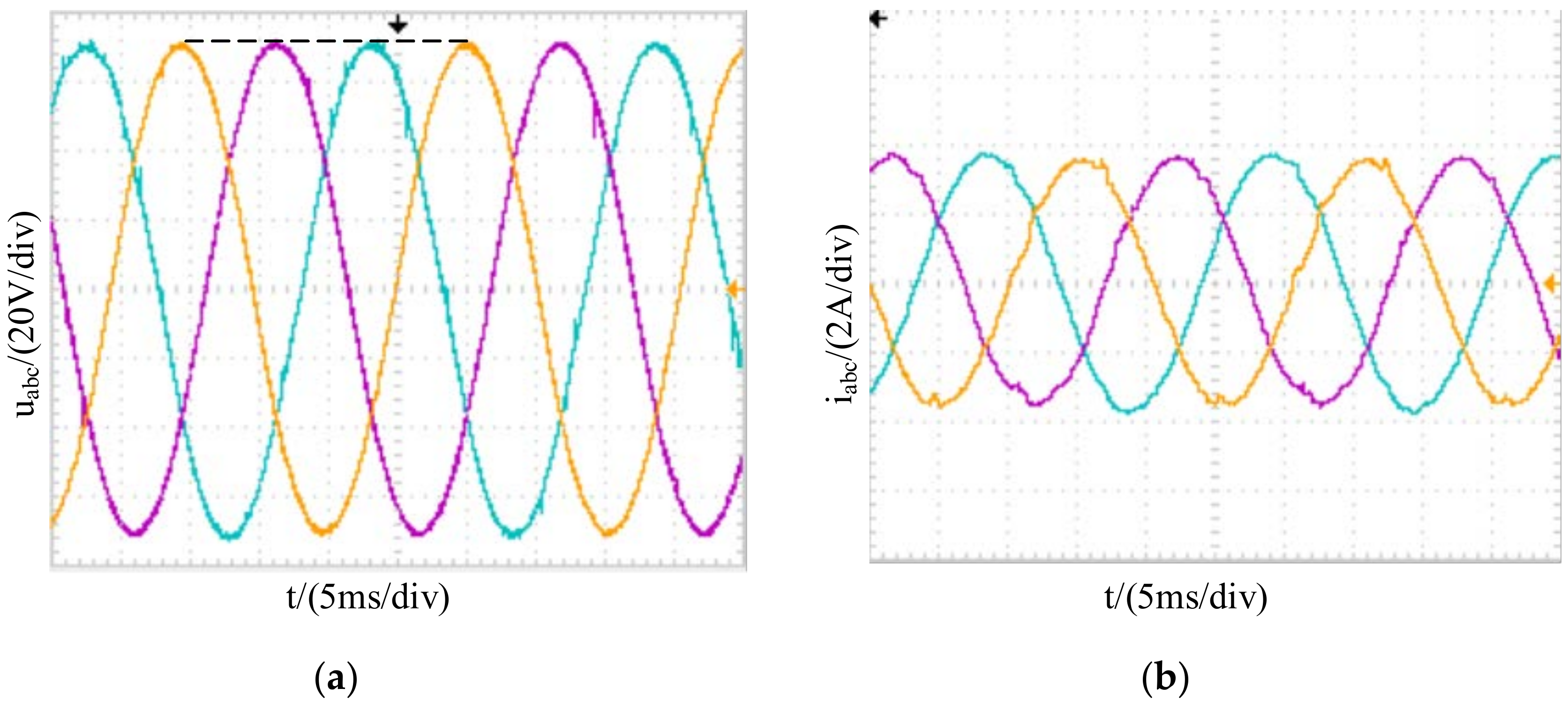
The experimental results with the traditional droop control under the conditions of the balanced load and the unbalanced load are shown in Figure 13 and Figure 14. It can be seen that three-phase output voltage is symmetrical with the conventional droop control strategy when the three-phase load is balanced. However, in the case of unbalanced three-phase load, the three-phase output voltage with the traditional droop control is obviously asymmetric.
Figure 15 shows the experimental results with improved droop control based on a self-adjusting P-f curve and Q-U curve in the case of unbalanced loads. It is known that the unbalanced degree of the three-phase output voltage becomes lower compared with that of Figure 14.
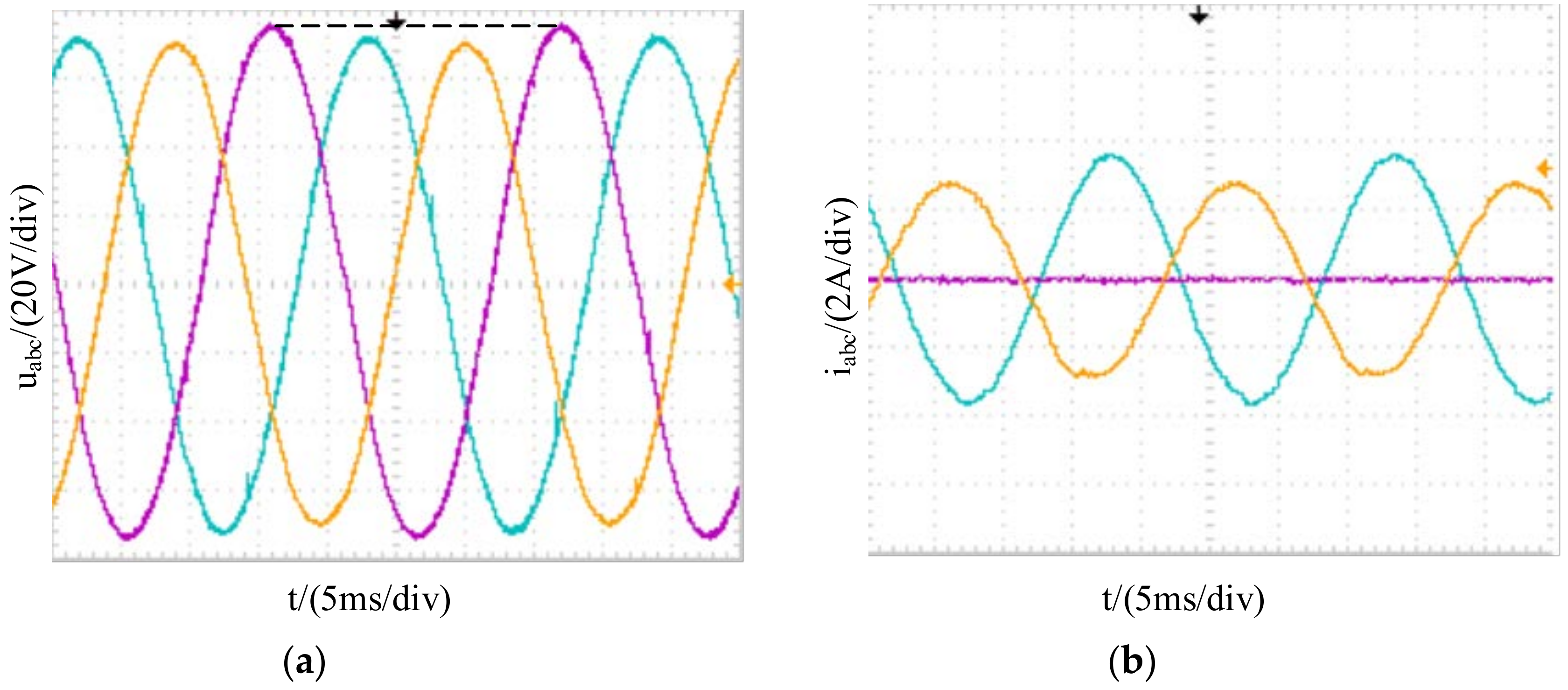
Figure 16 shows the experimental results with improved droop control and impedance voltage drop compensation control under the condition of unbalanced loads. It can be seen that, compared with the Figure 14, the output voltage symmetry can be improved by this comprehensive control strategy.
For the experimental results in Figure 14, Figure 15 and Figure 16, the asymmetrical degree of the three-phase voltage is calculated by MATLAB after the three-phase voltage dates are collected by a Tektronix TPS2024 oscilloscope. In Table 2, the unbalanced degree of the conventional droop control is up to 2.5%; the unbalanced degree of the three-phase output voltage only with the improved droop control is 0.55%; the unbalanced degree of the three-phase output voltage with the improved droop control and impedance voltage drop compensation control is only 0.25%.
5. Conclusions
There are a number of single-phase loads in the low voltage microgrid, and a combined three-phase inverter is adopted as the main circuit in this paper. The traditional droop controller will cause an asymmetry in the inverter output voltage when three-phase loads are unbalanced. An improved droop control strategy based on self-adjusting Q-U and P-f curves is proposed to adjust each phase droop curve in a real-time manner with the load variation and to get the symmetrical three-phase reference voltage signals. The influence of the inverter equivalent impedance on the output voltage symmetry is analyzed, and the impedance voltage drop compensation is added to the improved droop control to regulate the no-load voltage amplitude to ensure that the output voltage is symmetrical. Finally, a simulation and an experiment are carried out, and the results show that the unbalance degree is below 2% and meets the IEC require. The feasibility and effectiveness of the control strategy are verified. Compared with the control schemes for the three-phase three-line inverter and the three-phase four-leg inverter, the control scheme in this paper has the advantage of a simple control algorithm and minor calculations, due to no extractions of positive- and negative- and zero-sequence components and unnecessary power decoupling, its drawbacks are that there are four more power switches, and that the cost is slightly high.
Author Contributions
Conceptualization, B.R. and X.S.; methodology, B.R.; software, S.C.; validation, B.R., X.S., S.C. and H.L.; formal analysis, S.C.; investigation, H.L.; resources, X.S.; data curation, H.L.; writing—original draft preparation, B.R.; writing—review and editing, X.S.; visualization, X.S.; supervision, X.S.; project administration, X.S.; funding acquisition, B.R.
Funding
This research was funded by National Natural Science Foundation of China grant number 51477139 and Natural Science Foundation of Shaanxi Province grant number 2017JM5075.
Conflicts of Interest
The authors declare no conflict of interest.
Nomenclature
| X = a, b, c | Three-phase coordinate. |
| ω* | Angle frequency of voltage at no-load. |
| E* | Amplitude of voltage at no-load. |
| ωx | Angle frequency. |
| Ex | Voltage amplitude. |
| kp, kq | Droop coefficients of active power-frequency and reactive power-amplitude. |
| ox, | Inverter output voltage and output current. |
| Inverter filter inductance current. | |
| Px, Qx | Average active power and reactive power. |
| urefx, irefx | Reference voltage and reference current. |
| Zox | Inverter output impedance. |
| kvp, kr | Proportion coefficient and resonant coefficient of voltage controller. |
| ωh | Resonant bandwidth. |
| kc | Proportional coefficient of current controller. |
| Kpwm | Gain of pulse width modulation. |
| udc | DC link voltage. |
| L | Filter inductance. |
| Each-phase adjusted voltage amplitude at no load with improved droop control. | |
| ΔEx* | Impedance voltage drop compensation. |
| Peak value of AC bus voltage. | |
| Gv(s), Gi(s) | Transfer functions of voltage controller and current controller. |
| Gx(s) | System closed-loop transfer function. |
| Go(s) | System open-loop transfer function. |
| SPWM | Sinusoidal pulse width modulation. |
| VSC | Voltage source converter. |
| DER | Distributed energy sources. |
| APF | Active power filter. |
| STATCOM | Static synchronous compensator. |
| DG | Distributed generation. |
References
- Han, Y.; Shen, P.; Zhao, X.; Guerrero, J.M. Control Strategies for Islanded Microgrid Using Enhanced Hierarchical Control Structure with Multiple Current-Loop Damping Schemes. IEEE Trans. Smart Grid 2017, 8, 1139–1153. [Google Scholar] [CrossRef]
- Baghaee, H.R.; Mirsalim, M.; Gharehpetian, G.B. Three-phase AC/DC power-flow for balanced/unbalanced microgrids including wind/solar, droop-controlled and electronically-coupled distributed energy resources using radial basis function neural networks. IET Power Electron. 2017, 10, 313–328. [Google Scholar] [CrossRef]
- Dawoud, S.M.; Lin, X.; Okba, M.I. Hybrid renewable microgrid optimization techniques: A review. Renew. Sustain. Energy Rev. 2018, 82, 2039–2052. [Google Scholar] [CrossRef]
- Guerrero, J.M.; Loh, P.C.; Lee, T.L.; Chandorkar, M. Advanced control architectures for intelligent microgrids-part II: Power quality, energy storage, and AC/DC microgrids. IEEE Trans. Ind. Electron. 2013, 60, 1263–1270. [Google Scholar] [CrossRef]
- Ou, T.C.; Lu, K.H.; Huang, C.J. Improvement of Transient Stability in a Hybrid Power Multi-System Using a Designed NIDC. Energies 2017, 10, 488. [Google Scholar] [CrossRef]
- Lin, L.; Ma, H.; Bai, Z. An improved proportional load-sharing strategy for meshed parallel inverters system with complex impedances. IEEE Trans. Power Electron. 2017, 32, 7338–7351. [Google Scholar] [CrossRef]
- Marchiano, M.; David, M.J.; Rayworth, E.A. Power Generation Load Sharing Using Droop Control in an Island System. IEEE Trans. Ind. Appl. 2018, 54, 1890–1898. [Google Scholar] [CrossRef]
- Zhang, D.; Wang, F.F.; Burgos, R.; Boroyevich, D. Common-mode circulating current control of paralleled interleaved three-phase two-level voltage-source converters with discontinuous space-vector modulation. IEEE Trans. Power Electron. 2011, 26, 3925–3935. [Google Scholar] [CrossRef]
- Hosseinzadeh, M.; Farzad, R.S. Robust Optimal Power Management System for a Hybrid AC/DC Micro-Grid. IEEE Trans. Sustain. Energy 2015, 6, 675–687. [Google Scholar] [CrossRef]
- Hosseinzadeh, M.; Farzad, R.S. Power management of an isolated hybrid AC/DC micro-grid with fuzzy control of battery banks. IET Renew. Power Gener. 2015, 9, 484–493. [Google Scholar] [CrossRef]
- Leonardo, R.L.; Fabricio, B.; Calebe, H.O.L.; Marcelo, C.C. Reactive power and current harmonic control using a dual hybrid power filter for unbalanced non-linear loads. Energies 2018, 11, 1392. [Google Scholar]
- Han, Y.; Shen, P.; Zhao, X.; Josep, M.G. An enhanced power sharing scheme for voltage unbalance and harmonics compensation in an islanded ac microgrid. IEEE Trans. Energy Convers. 2016, 31, 1037–1050. [Google Scholar] [CrossRef]
- Mehdi, S.; Alireza, J.; Juan, C.V.; Josep, M.G. Secondary control scheme for voltage unbalance compensation in an islanded droop-controlled microgrid. IEEE Trans. Smart Grid 2012, 3, 797–807. [Google Scholar]
- Mehdi, S.; Alireza, J.; Juan, C.V. Autonomous Voltage Unbalance Compensation in an Islanded Droop-Controlled Microgrid. IEEE Trans. Ind. Electron. 2013, 60, 1390–1402. [Google Scholar] [Green Version]
- Liu, Q.; Tao, Y.; Liu, X.; Deng, Y.; He, X. Voltage unbalance and harmonics compensation for islanded microgrid inverters. IET Power Electron. 2014, 7, 1055–1063. [Google Scholar] [CrossRef]
- Vyawahare, D.; Chandorkar, M. Distributed generation system with hybrid inverter interfaces for unbalanced loads. In Proceedings of the 2015 IEEE 6th International Symposium on Power Electronics for Distributed Generation Systems, Aachen, Germany, 22–25 June 2015. [Google Scholar]
- Quentin, T.; Ionel, V.; Aitor, E. Hybrid Energy Storage System Microgrids Integration for Power Quality Improvement Using Four-Leg Three-Level NPC Inverter and Second-Order Sliding Mode Control. IEEE Trans. Ind. Electron. 2018, 65, 424–435. [Google Scholar]
- Ruben, L.; Juan, M.M.; Antonio, G.E.; Mehdi, S.; Josep, M.G. Grid-forming VSC control in four-wire systems with unbalanced nonlinear loads. Electr. Power Syst. Res. 2017, 152, 249–256. [Google Scholar] [Green Version]
- Ou, T.C. A novel unsymmetrical faults analysis for microgrid distribution systems. Int. J. Electr. Power Energy Syst. 2012, 43, 1017–1024. [Google Scholar] [CrossRef]
- Bina, M.T.; Kashefi, A. Three-phase unbalance of distribution systems: Complementary analysis and experimental case study. Int. J. Electr. Power Energy Syst. 2011, 33, 817–826. [Google Scholar] [CrossRef]
- Ritwik, M.; Balarko, C.; Arindam, G.; Rajat, M.; Gerard, L.; Firuz, Z. Improvement of stability and load sharing in an autonomous microgrid using supplementary droop control loop. IEEE Trans. Power Syst. 2010, 25, 796–808. [Google Scholar]
- Qobad, S.; Josep, M.G.; Juan, C.V. Distributed secondary control for islanded microgrids-a novel approach. IEEE Trans. Power Electron. 2014, 29, 1018–1031. [Google Scholar]
- Han, Y.; Li, H.; Shen, P.; Ernane, A.A.C.; Josep, M.G. Review of active and reactive power sharing strategies in hierarchical controlled microgrids. IEEE Trans. Power Electron. 2017, 32, 2427–2451. [Google Scholar] [CrossRef]
- He, J.; Li, Y.; Frede, B. An enhanced islanding microgrid reactive power, imbalance power, and harmonic power sharing scheme. IEEE Trans. Power Electron. 2015, 30, 3389–3401. [Google Scholar] [CrossRef]
Figure 1.
Simplified microgrid structure.

Figure 2.
Structure architecture of the combined three-phase inverter.

Figure 3.
General block diagram of the control scheme for the parallel inverters.

Figure 4.
Block diagram of the voltage and current control loops.

Figure 5.
Main circuit and the control scheme.

Figure 6.
Block diagram of the control scheme. (a) Average power calculation; (b) Improved droop control and impedance voltage drop compensation; (c) Synthesis process of the reference voltage; (d) Voltage and current control loops.
Figure 6.
Block diagram of the control scheme. (a) Average power calculation; (b) Improved droop control and impedance voltage drop compensation; (c) Synthesis process of the reference voltage; (d) Voltage and current control loops.

Figure 7.
Flowchart of the designed control scheme.
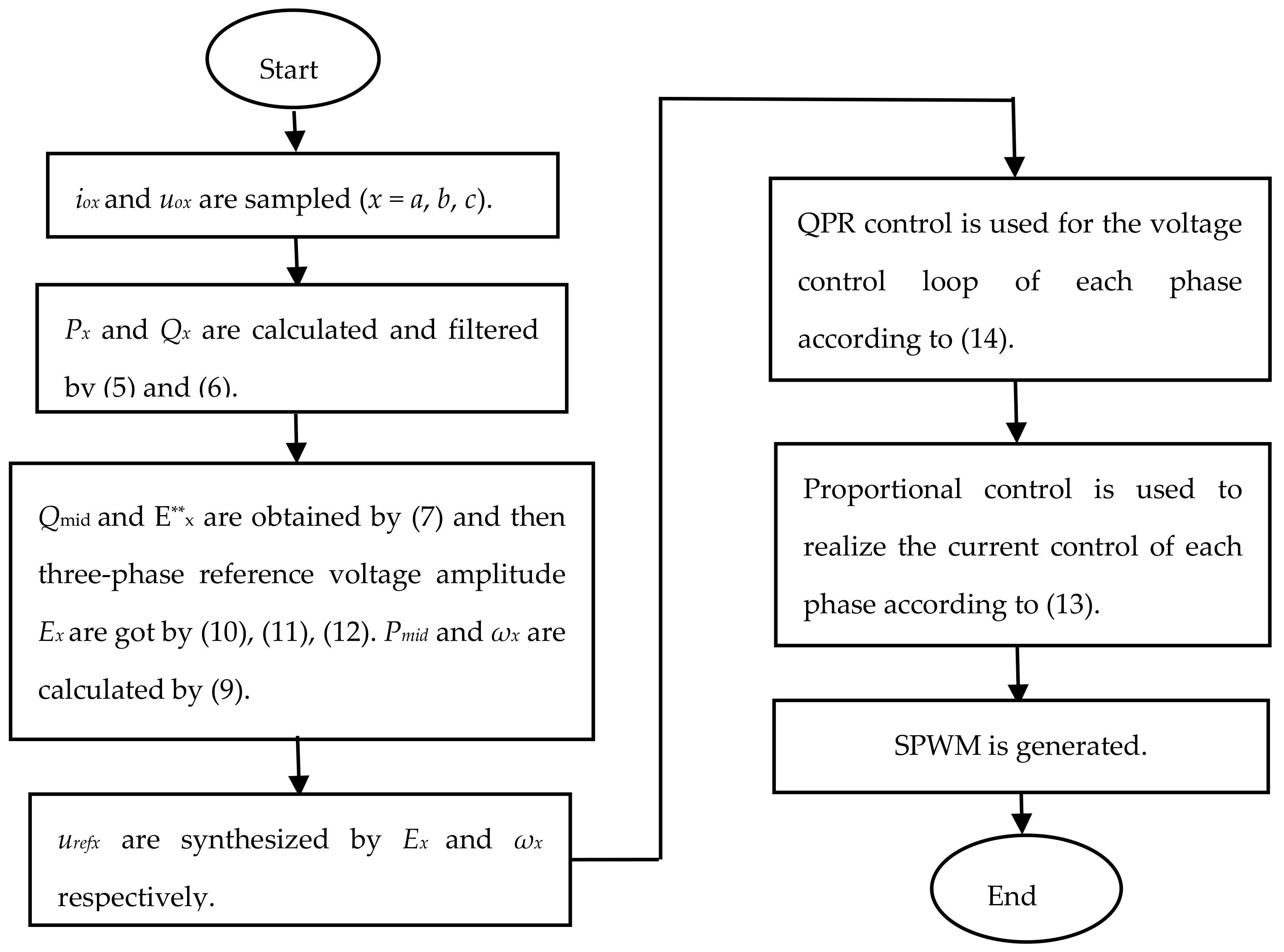
Figure 8.
Q-U droop curves. (a) Traditional Q-U droop curve; (b) Improved Q-U droop curve.

Figure 9.
Bode diagram of the system open-loop transfer function.

Figure 10.
Simulation waveforms under various load conditions. (a) Three-phase load active powers; (b) Three-phase load reactive powers; (c) load currents.
Figure 10.
Simulation waveforms under various load conditions. (a) Three-phase load active powers; (b) Three-phase load reactive powers; (c) load currents.

Figure 11.
Voltage waveforms with the traditional droop control. (a) Frequencies of the three-phase reference voltage; (b) amplitudes of the three-phase reference voltage; (c) instantaneous output voltage.
Figure 11.
Voltage waveforms with the traditional droop control. (a) Frequencies of the three-phase reference voltage; (b) amplitudes of the three-phase reference voltage; (c) instantaneous output voltage.
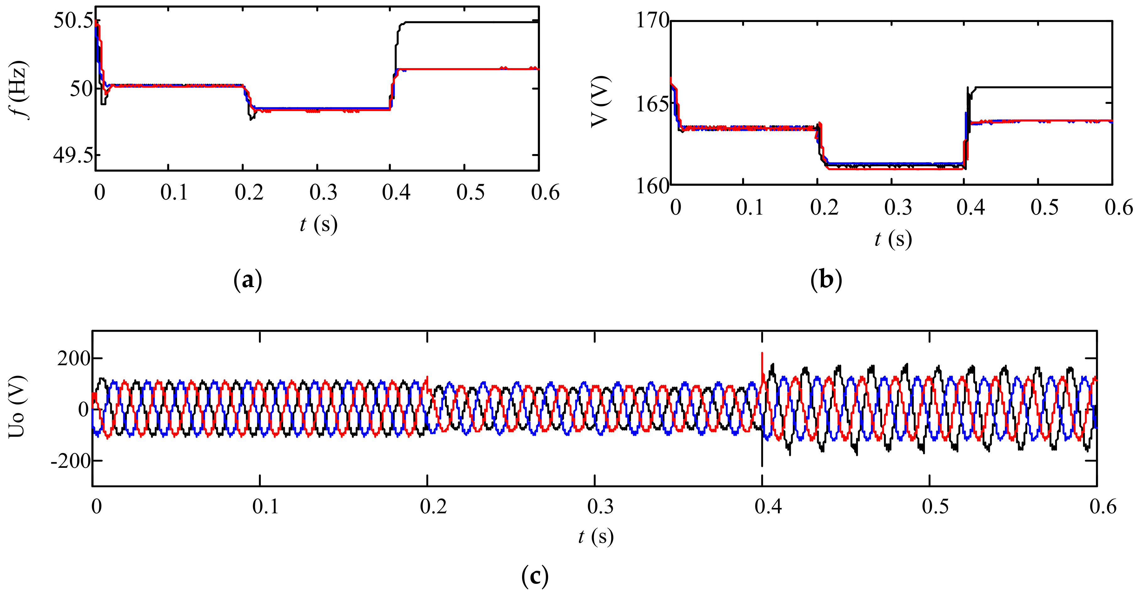
Figure 12.
Voltage waveforms with the proposed control method. (a) frequencies of the three-phase reference voltage; (b) amplitudes of the three-phase reference voltage; (c) instantaneous output voltage.
Figure 12.
Voltage waveforms with the proposed control method. (a) frequencies of the three-phase reference voltage; (b) amplitudes of the three-phase reference voltage; (c) instantaneous output voltage.


Figure 13.
Experimental waveforms of three-phase output voltages and currents with traditional droop control in the case of a balanced load. (a) Voltage waveforms; (b) Current waveforms.
Figure 13.
Experimental waveforms of three-phase output voltages and currents with traditional droop control in the case of a balanced load. (a) Voltage waveforms; (b) Current waveforms.

Figure 14.
Experimental waveforms of three-phase output voltages and currents with traditional droop control in the case of an unbalanced load. (a) Voltage waveforms; (b) Current waveforms.
Figure 14.
Experimental waveforms of three-phase output voltages and currents with traditional droop control in the case of an unbalanced load. (a) Voltage waveforms; (b) Current waveforms.

Figure 15.
Three-phase output voltages and currents only with the improved droop control in the case of an unbalanced load. (a) Voltage waveforms; (b) Current waveforms.
Figure 15.
Three-phase output voltages and currents only with the improved droop control in the case of an unbalanced load. (a) Voltage waveforms; (b) Current waveforms.
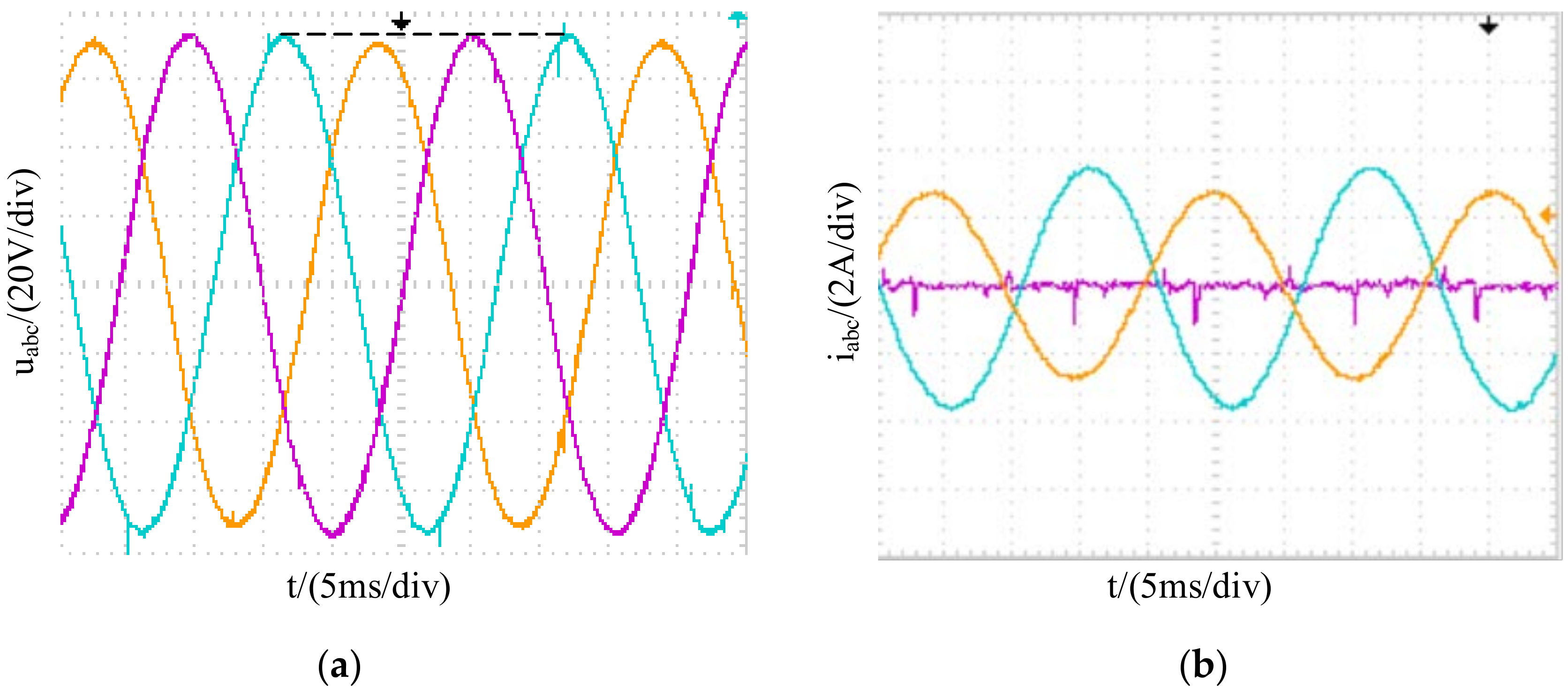
Figure 16.
Three-phase output voltages and currents with improved droop control and impedance-drop compensation control in the case of an unbalanced load. (a) Voltage waveforms; (b) Current waveforms.
Figure 16.
Three-phase output voltages and currents with improved droop control and impedance-drop compensation control in the case of an unbalanced load. (a) Voltage waveforms; (b) Current waveforms.
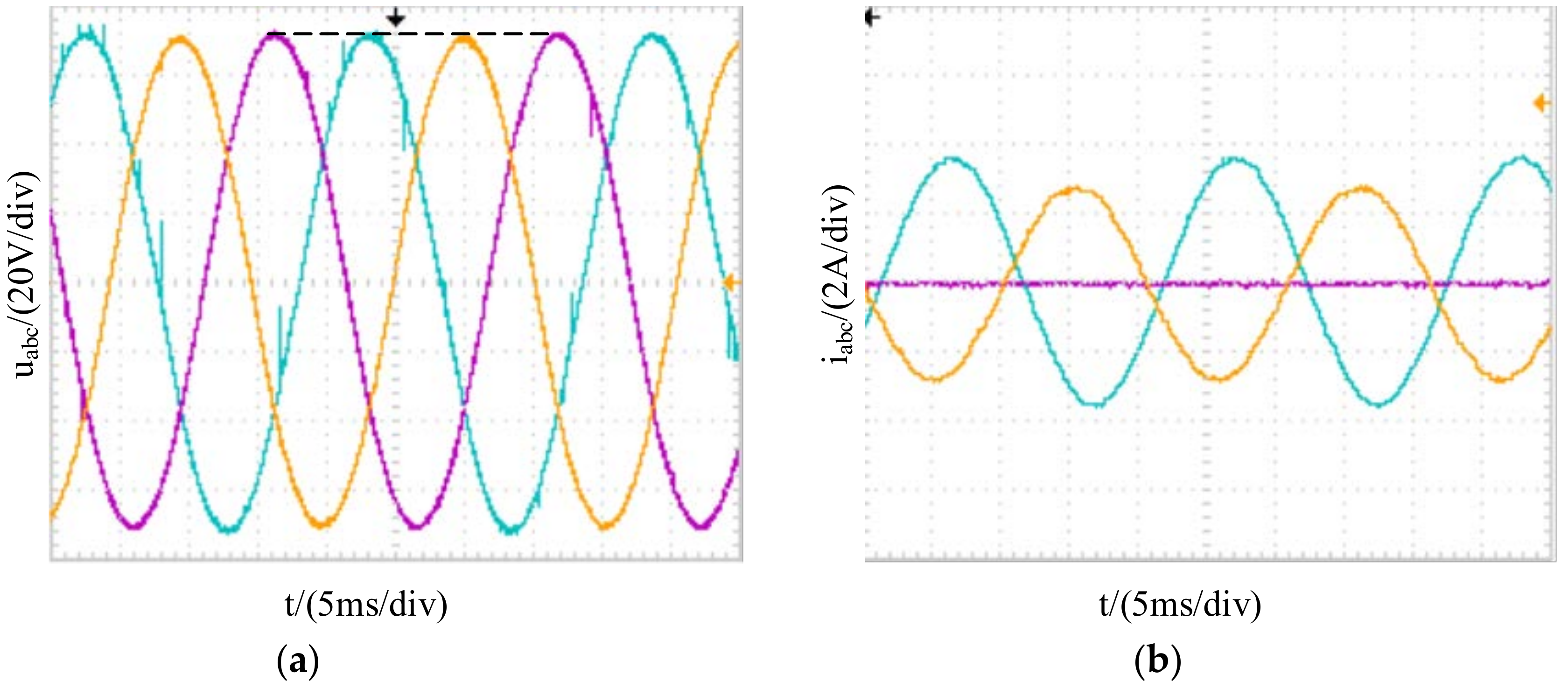
Figure 17.
Three-phase output voltages and c-phase current of switching from unbalanced load to balanced load.
Figure 17.
Three-phase output voltages and c-phase current of switching from unbalanced load to balanced load.
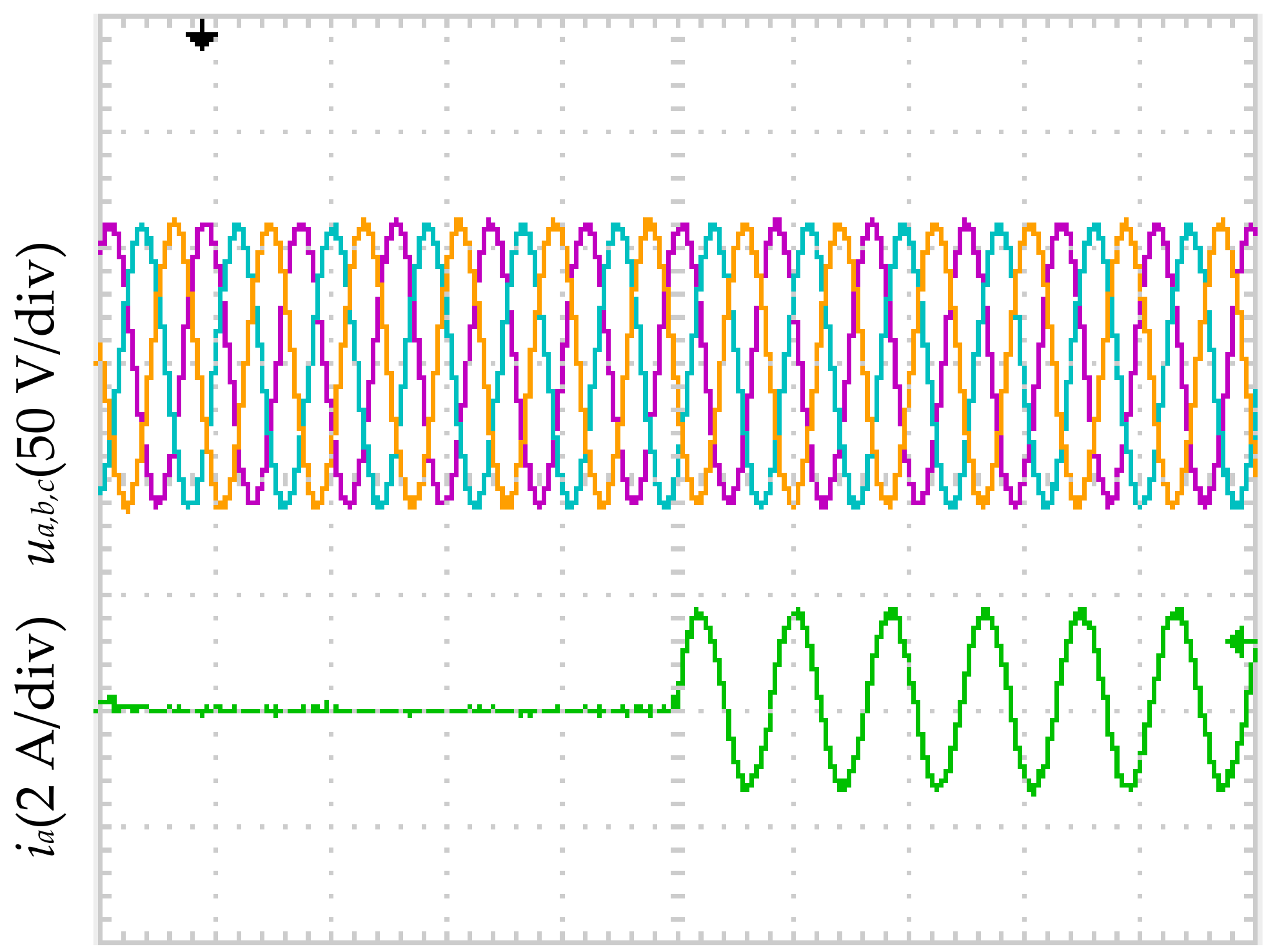
Figure 18.
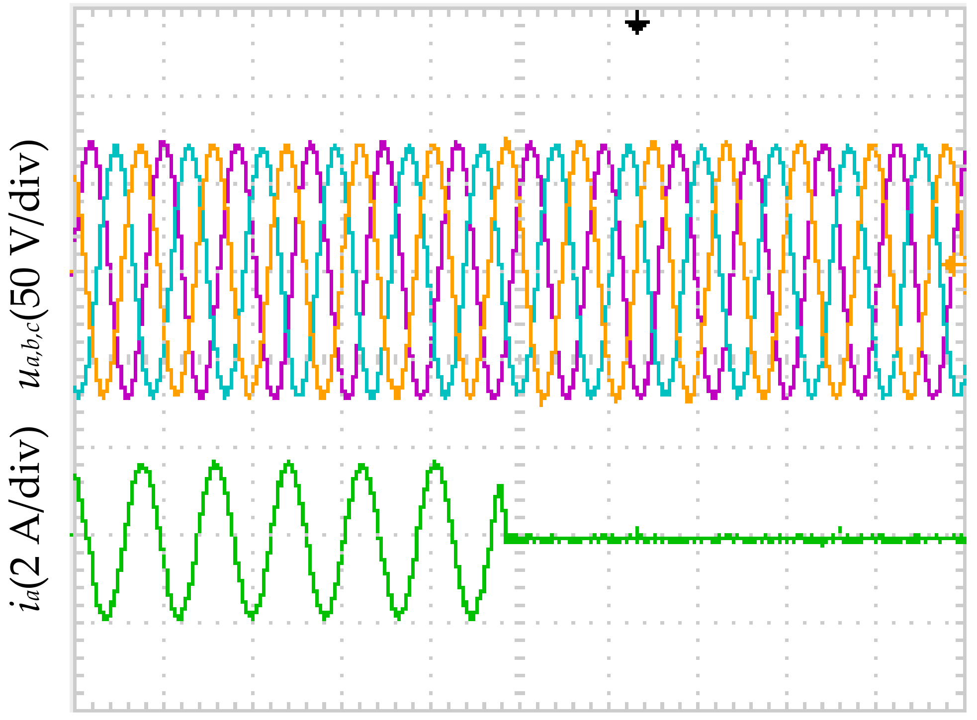
Three-phase output voltages and c-phase current of switching from balanced load to unbalanced load.
Figure 18.
Three-phase output voltages and c-phase current of switching from balanced load to unbalanced load.

Table 1.
System parameters.
| Parameters | Value |
|---|---|
| Filter inductor La, Lb, Lc (mH) | 0.85 |
| Filter capactior Ca, Cb, Cc (uF) | 30, 30, 30 |
| Direct current bus voltage Udc (V) | 100 |
| Balanced three-phase load Ra, Rb, Rc | 40 Ω |
| Unbalanced three-phase load Za, Zb, Zc | 40 Ω + 80 mh, 80 Ω + 40 mh, 0 |
| Switching frequency (Hz) | 10 k |
| Droop coefficient kp, kq | 8.5 × 10⁻⁵, 1 × 10⁻⁴ |
| Voltage controller kvp and kr | 10.113, 0.18 |
| Current controller kc | 9.8814 |
| Impedance voltage drop compensation kup, kui | 0.3, 7 |
| Kpwm | 1 |
Table 2.
Unbalanced degree of three-phase voltage for three strategies with unbalanced loads.
| Control Strategy | Unbalanced Degree/% |
|---|---|
| Traditional droop control | 2.5 |
| Improved droop control | 0.55 |
| Improved droop control and impedance Voltage drop compensation | 0.25 |
© 2018 by the authors. Licensee MDPI, Basel, Switzerland. This article is an open access article distributed under the terms and conditions of the Creative Commons Attribution (CC BY) license (http://creativecommons.org/licenses/by/4.0/).
Share and Cite
MDPI and ACS Style
Ren, B.; Sun, X.; Chen, S.; Liu, H. A Compensation Control Scheme of Voltage Unbalance Using a Combined Three-Phase Inverter in an Islanded Microgrid. Energies 2018, 11, 2486. https://doi.org/10.3390/en11092486
AMA Style
Ren B, Sun X, Chen S, Liu H. A Compensation Control Scheme of Voltage Unbalance Using a Combined Three-Phase Inverter in an Islanded Microgrid. Energies. 2018; 11(9):2486. https://doi.org/10.3390/en11092486
Chicago/Turabian StyleRen, Biying, Xiangdong Sun, Shasha Chen, and Huan Liu. 2018. "A Compensation Control Scheme of Voltage Unbalance Using a Combined Three-Phase Inverter in an Islanded Microgrid" Energies 11, no. 9: 2486. https://doi.org/10.3390/en11092486
Note that from the first issue of 2016, this journal uses article numbers instead of page numbers. See further details here.