Locating Fault on Transmission Line with Static Var Compensator Based on Phasor Measurement Unit


Faculty of Engineering and Technology, Quy Nhon University, Binh Dinh 820000, Vietnam
*
Author to whom correspondence should be addressed.
Energies 2018, 11(9), 2380; https://doi.org/10.3390/en11092380
Submission received: 23 August 2018
/
Revised: 5 September 2018
/
Accepted: 7 September 2018
/
Published: 9 September 2018
(This article belongs to the Section F: Electrical Engineering)
Abstract
:The flexible alternating current transmission systems (FACTS) have been widely used in modern power systems. Because of the presence of the FACTS devices, distance relays in transmission lines may inaccurately locate fault locations. Therefore, it is significant to find a mechanism for locating fault in transmission lines connected to FACTS in which a static var compensator (SVC) is investigated in this work. Based on the development of a phasor measurement unit (PMU) with global positioning system (GPS), this paper proposes a new method for calculating apparent impedance seen by the distance relay location while a short-circuit fault occurs in a transmission line connected the SVC to the midpoint of the line. According to the method, sampled voltage and current measurement at the relay and SVC locations are synchronized using PMUs and the synchronized measurements are then used to calculate a new apparent impedance and to locate the fault location in the line. The method in this paper has the capability for fast calculation and it also has the robustness for identifying different fault types in power systems. Matlab/Simulink software is applied to simulate the study results and to evaluate the correctness of the modeling and effectiveness of the proposed method for locating fault in this paper.
1. Introduction
Distance protection relays are widely used as the main protection scheme for transmission lines in power systems. A digital distance relay operates based on the measured impedance calculated from sampled voltage and current data at the relay locations at substations. The setting of distance relays’ operating zones is obtained from the line impedance protected by the relay. During a short-circuit fault, the apparent impedance trajectory falls inside the operating zones and as a consequence of the trip signal will be sent to the associated circuit breaker to disconnect the faulty line in order to maintain the normal operating mode of the power system [1,2]. Recently, the flexible alternating current transmission systems (FACTS) controllers in power systems have been used to improve power transfer capability and enhance controllability and stability of the power system [3,4]. However, the FACTS devices may also cause the transmission line to lead to deterioration of distance relay operation resulting in inaccurate estimation of short-circuit fault location in transmission lines such as over-reach and under-reach for different cases [5,6,7]. The improper working of distance relay can lead to incorrect tripping and it not only decreases the reliability and security of the power system but also can institute the cascade tripping and blackouts in the system [8].
There exists literature on the performance of distance protection relay in transmission lines with the presence of the shunt FACTS devices [5,9,10,11,12]. The work in [5] presented the performance of the distance protection relay of transmission lines with the shunt FACTS devices. The performance of the distance relay was evaluated for the shunt FACTS devices applied for midpoint voltage control. The impact of two types of shunt FACTS controllers including the static var compensator (SVC) and the static synchronous compensator (STATCOM) on the distance protection relay were studied for different fault types, fault locations and system conditions in power systems. The results in the paper showed the adverse effects of the midpoint shunt FACTS compensation of transmission line on both non-pilot and directional comparison blocking distance protection schemes. The authors Singh and Rajiv in [9] also considered the performance of the distance protection relays which were applied to protect the shunt FACTS compensated transmission lines. The shunt FACTS devices were assumed for connecting to the midpoint of the line and the study was carried out in three stages including analyzing analytically the errors introduced in the impedance measurement due to the presence of the shunt FACTS devices on the line, using transient simulation software, EMTDC to simulate the response of these devices for different fault conditions and system conditions, and confirming the findings by testing the commercial relay validate the analytical and simulation studies. The measured impedance at the relaying point in the presence of SVC was studied in [10]. In the paper, the measured impedance at the relaying point was calculated due to the effective parameters to confirm that the presence of SVC on a transmission line had a great influence on the tripping characteristic of the distance relays in power systems. In addition, its controlling parameters as well as its installation location also affected the tripping characteristic of the distance protection relay. In [11], Albasri et al. made a comparative study of the performance of distance protection relays for transmission lines compensated by shunt FACTS controllers/devices including SVC and STATCOM also applied for midpoint voltage control. The impact of these devices was studied to evaluate their influence on the performance of various the distance protection schemes on transmission lines for different fault types, fault locations, and system conditions. The work published in [12] analyzed the impact of STATCOM on the apparent impedance seen by the conventional distance relay protecting a transmission line. Analytical and simulation results were carried out in the paper to confirm that the implication of applying STATCOM on the distance relay was highly dependent on the sophisticated modeling of STATCOM especially its control system considering practical constraints. Moreover, different power system operating conditions, STATCOM control system settings and fault scenarios investigated showed the STATCOM effects on the distance relay tripping characteristics dramatically.
For mitigating the influence of shunt FACTS devices on distance protection relay and making adaptive distance protection relay tripping characteristics in power systems, there are many published works recently [13,14,15,16,17,18,19,20]. In [13], the influence of SVC at the midpoint of transmission line on distance relay operation was analyzed. It made a result in inaccurate estimation of faults locations i.e., over-reach or under reach for the different cases. The paper proposed a new algorithm that utilized synchronized phasor measurements to improve the operation of adaptive distance protection zone in many aspects. The authors of the paper [14] also proposed an adaptive distance protection scheme for improving the performance of the conventional distance protection scheme for shunt FACTS compensated line connecting farm. The adaptive tripping characteristics for high resistance line-to-ground fault with the shunt-FACTS devices considering appropriate operating conditions was addressed in the paper. The work in [15] proposed an adaptive distance relay algorithm for the shunt compensated transmission line. The STATCOM was the shunt device studied in the paper to investigate its impact on the performance of the distance protection relay on the line. An adaptive zone setting for distance relay tripping characteristics was proposed and evaluated for different types of faults different types of fault, different fault resistances, and load angles. The wavelet approach for transient current based multi terminal transmission system protection scheme in the presence of SVC was studied and proposed in [16]. The work carried out the most important problem of the distance protection was severe under reaching, which was caused by current injection at the point of connection to the system. Then, the paper proposed an efficient method based on wavelet transform, which was used for finding the detailed coefficients of the signals utilized to calculate fault index. The method was evaluated for the detection, classification, and location of the fault on transmission line connected to a SVC. The work presented in [17] studied practical solutions for mitigating the adverse impacts on the distance protection schemes used to protect transmission lines that were compensated by FACTS controllers/devices including SVC and STATCOM. The modifications were proposed for mitigating these impacts and implementing in commercial relays under various faults and varying operating conditions. In addition, application of an adaptive neuro-fuzzy inference system (ANFIS), high-frequency voltage standing-wave ratio-based grounding electrode line fault supervision and transient fault current sensor based on the Rogowski coil were researched in [18,19,20] for modeling the distance protection relay, identifying the transient current faults, and mitigating the effects of FACTS on the distance protection relay in power systems.
A PMU is a device that is used to measure the phasor values of current and voltage on an electricity grid using a common time source for synchronization. Time synchronization allows synchronized real-time measurements of multiple remote measurement points on the grid. PMUs are considered to be one of the most important measuring devices in the future of power systems [21,22]. For protection relay in power systems, PMUs were studied for purpose of locating fault in transmission line [23,24,25]. In [23], the fault location techniques for transmission lines based on PMU data were presented. The two-ended data were assumed to be measured by PMUs to identify the fault location on transmission lines. The work presented in [24] proposed an algorithm for distance protection and fault location based on PMU. The algorithm was applied for series-compensated transmission lines and utilized the PMU to develop a distance protection and fault location scheme using synchronized voltage and current measurements from both local and remote end substations. Moreover, for fault location and isolation for redundant inertial measurement unit under quantization, the authors in [25] proposed a method using the three-channel filters to detect the soft fault and conducts theoretical implementation and the Monte Carlo simulation was carried out in order to verify the validity of the fault detection and isolation with redundant strap down inertial measurement unit. The work in [26] designed an adaptive fault-tolerant control (FTC) scheme using the hybrid of the dynamic surface control technique and adaptive first-order filters to reduce significantly the computational burden and improve further the control performance. Al-Mohammed et al. reported a comprehensive survey of fault location based on synchronized measurements [27]. The paper addressed the advantages and disadvantages of the existing methods for locating fault based on PMU and also highlighted the area for future research.
To address the aforementioned problems, this paper developed a simple power system modeling including a transmission line connected a SVC at the midpoint of the transmission line and single-phase faults are established to research the problems. A new method uses PMUs’ measurements at the distance protection relay and SVC locations for calculating the apparent impedance seen by the relay on the line and then it was used for locating fault location on the line connected SVC at the midpoint location. The rest of this paper is structured as follows. Section 2 presents the background of the proposed method for locating the fault in transmission line connected to a SVC at the midpoint of the line. Section 3 establishes the simulation modeling in Matlab/Simulink software (R2011b.) and analyzes the simulation results to evaluate the proposed method. Finally, the paper is concluded with Section 4.
2. Materials and Methods
2.1. The Study Power System
The one-line diagram of the study power system developed in this paper is shown in Figure 1. The system comprises a 220 kV transmission line with the length of 200 km and two substations connected to two ends of the line. In addition, a SVC is connected to the midpoint of the line. The current transformers (CTs) and voltage transformers (VTs) are placed at two ends and the midpoint of the line to measure currents and voltages at the locations. The feasible and simple method is proposed in this paper in which the currents and voltages are measured at the relay and SVC locations with the support of PMUs. Using high-speed optical fiber data communication, these signals are then transmitted to the relay location to calculate apparent impedance and locate the fault in the line.
2.2. Phasor Measurement Unit (PMU)
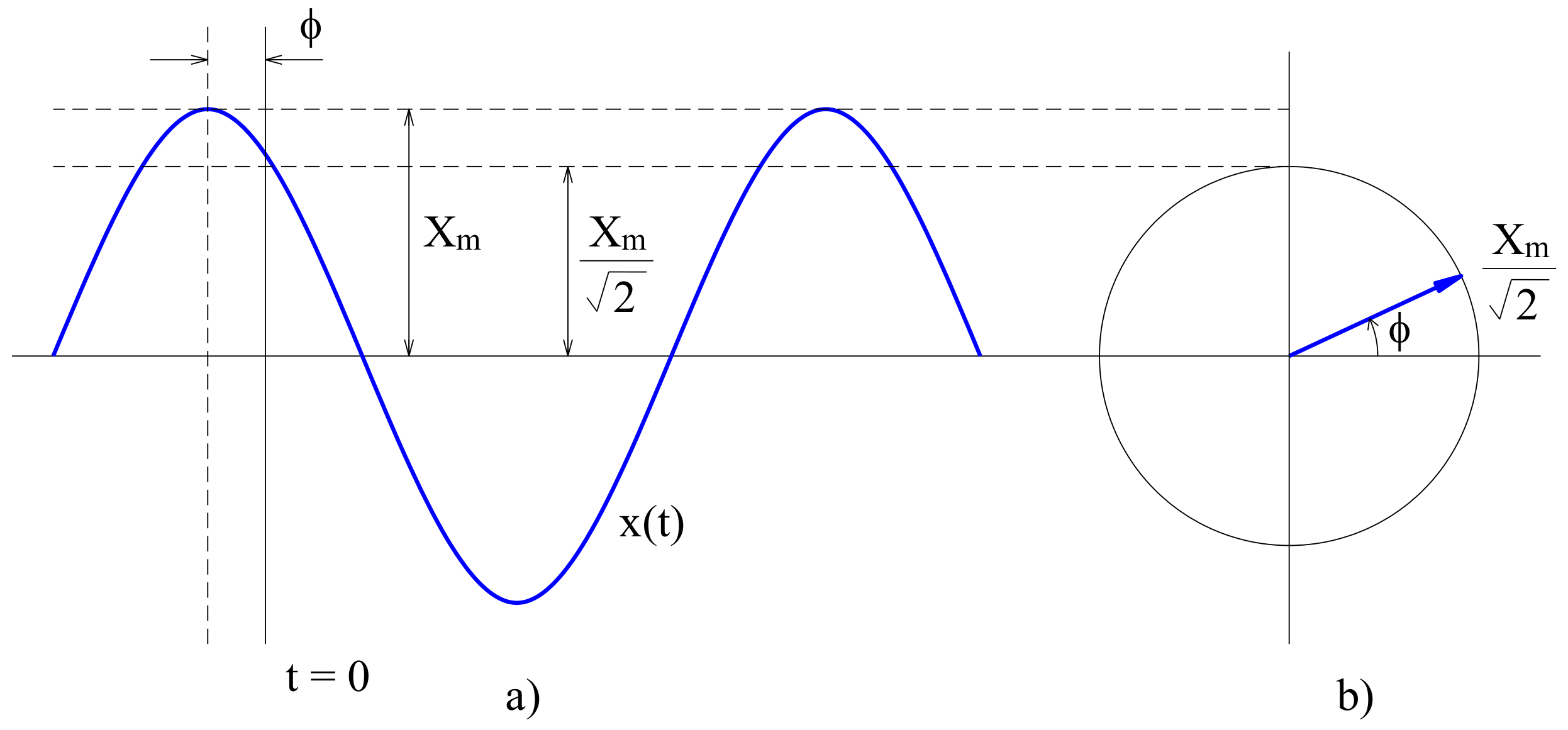
The PMU is used in power systems to provide real-time synchronized measurements with better than one microsecond synchronization accuracy, which is obtained by GPS signals. The PMU technology establishes both the magnitude and phase angle of phasor information in real time. An advantage of referring phase angle to global reference time is useful for capturing a wide area snapshot of power systems [24]. Effective application of this technology is helpful for mitigating blackouts and learning real-time behavior of power system. A phasor is a complex number that represents both the magnitude and phase angle of the sine waveform found in alternating current system. The waveform can be represented as follows:
where is the magnitude of the sinusoidal waveform; is the instantaneous frequency of the signal in radians per second; and is the phase angle. In phasor notation, it can be represented as follows:
where is the root mean square (RMS) value of the sinusoidal waveform.
From the real axis, positive phase angles are calculated in a counterclockwise direction. Because the frequency of the sinusoidal is inherent in the phasor definition, it is clear that all phasors involved a single phasor diagram must have the same frequency [27]. Phasor representation of the sinusoidal waveform means that the signal maintains stationary at all times, leading to a constant phasor representation as shown in Figure 2. These concepts must be modified when practical phasor measurements are to be carried out for the input signals are not constant, and their frequency may be a variable. Currents and voltages obtained from the secondary winding of CTs and VTs located in substations are the analog inputs to the PMU. All three phase currents and voltages are used to carry out the positive sequence measurement. The current and voltage signals are converted to voltages with appropriate shunts or instrument transformers to match with the requirements of the analog-to-digital (A/D) converters.
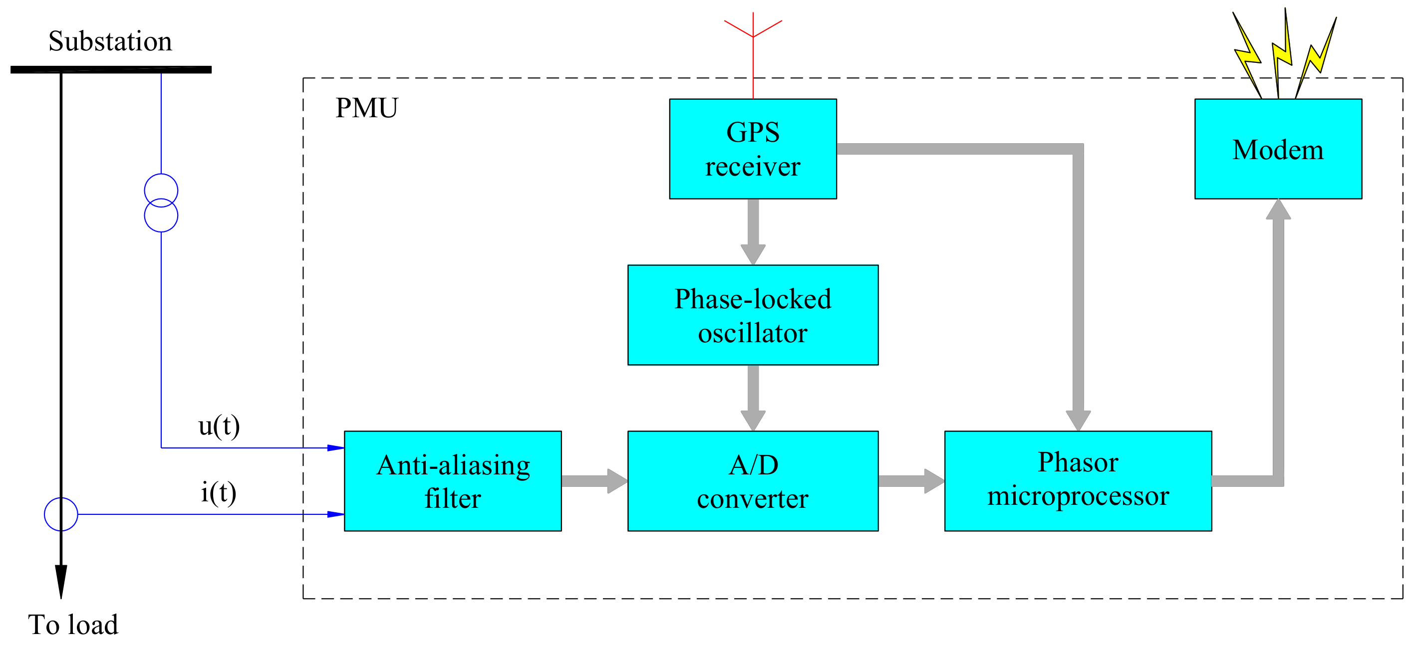
Figure 3 shows a block diagram representation of PMU. In Figure 3, the anti-aliasing filter restricts bandwidth of signal to satisfy a sampling theorem, the A/C converter converts the analog input signal to digital output signal, the GPS receiver provides a time stamp for the signal, the phase-locked oscillator keeps frequency of the reference and measured signal equal, the phasor microprocessor measures the phasor values of current and voltage and the modem is used to transfer the phasor values to other position in power system.
2.3. The Proposed Algorithm
Synchrophasors are time-synchronized numbers that represent both the magnitude and phase angle of the sine waves found in electricity and are time-synchronized for accuracy. They are measured by PMUs and are also used to improve power system operation such as relays and stabilizers. The method in this paper uses PMUs mentioned in Section 2.2 to measure the required current and voltage data at different placements and send them to the power system control centers. Then, these data can be used for generating proper control signals and improving the power system operation. In this method, optical fibers are used as the communication channels for transmitting the data. Because the data is transmitted from different locations on the power system with different time delays, GPS is used for synchronizing and making them time stamped [28]. Based on the method, sampled voltage and current measurement at the relay and SVC locations are synchronized using PMUs. The synchronized measurement is then used to calculate a new apparent impedance and locate the fault location on the line in which the SVC is located at the midpoint. To evaluate the proposed method, the distance protection relay A is considered for analyzing the simulation results in this paper. In Figure 4, the sequence networks of the study system are shown. The new expression of apparent impedance at the relay A is derived using sequence components of synchronized voltage and current measurement based on PMUs at relay and SVC locations.
When an SVC is connected at the midpoint of the line and a short-circuit fault (F) occurs on the segment line between the SVC and the substation B as shown in Figure 1, the sequence components of current and voltage at the relay A are expressed as follows:
where , , and are positive, negative and zero sequence currents at the relay A, respectively; , , and are positive, negative and zero sequence currents at the SVC, respectively; , , and are positive, negative and zero sequence currents on the line segment between the SVC and the fault locations, respectively; , , and are positive, negative and zero sequence fault currents, respectively; , , and are positive, negative and zero sequence voltages at the relay A, respectively; , , and are positive, negative and zero sequence line impedance, respectively; is fault resistance; and x is the length of the segment from the relay A to the fault location in per unit. The phase-a voltage at the relay A is which can be determined from the sequence components as follows:
In fact, the zero-sequence current component of the SVC () can be eliminated because of delta connection at one side of the coupling transformer which is used to connect the SVC to the system. In addition, we consider that therefore Equation (9) can be rewritten as follows:
The expression of apparent impedance () at the relay A which is defined by the conventional method is expressed as follows:
where K is the compensation factor and given by
The distance protection algorithm proposed for the main purpose of this paper is to make distance protection algorithm for locating fault when SVC is connected at the midpoint of the transmission line. The apparent impedance seen by the relay A can be determined by the segment line impedance from the relay A to SVC and the segment line impedance from SVC to fault location. Therefore, based on the approach for calculating apparent impedance at the distance relay [1], the proposed algorithm in this paper uses voltage and current measurement both of the SVC and the relay A location to determine the new expression of apparent impedance at the relay A as follows:
where , and are the voltages at the relay A and SVC locations, respectively.
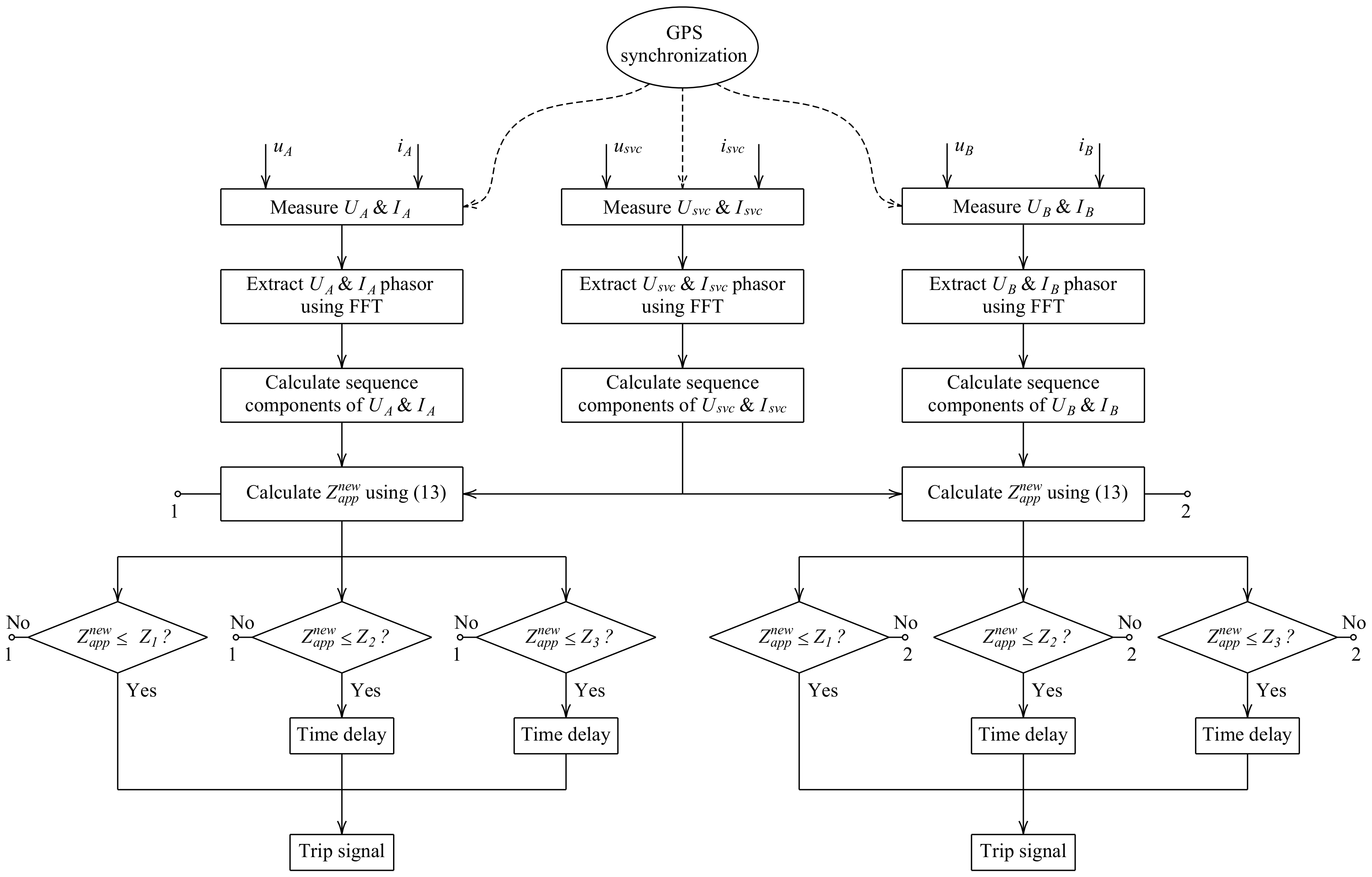
From Equation (13), we can see clearly that the apparent impedance at the relay A is a function of voltage and current at the relay A location (, ), voltage and current at the SVC location (, ). The digital distance relay A takes the voltage and current samples from instrument transformers at the relay A and SVC locations. In order to calculate phasor (fundamental only), the voltage and current samples are pre-processed using fast Fourier transform (FFT). The symmetrical voltages and currents are used to calculate the apparent impedance () at the relay A location. Finally, it is compared with the setting zones of the Mho characteristic to make trip signal as shown in Figure 5. In power systems, distance relay acts as the main protection for faults within zone 1, while, for zone 2 and zone 3, it acts as a backup protection for the adjacent line. Zone 1 reach is normally set only up to 80–90% of the protected line. For ensuring full coverage of the protected line, zone 2 is set at minimum of the protected line. For faults within zone 2 reach, tripping signal will be sent at a delayed time where the relay acts as the backup protection for the main protection at the adjacent line. The tripping time for zone 2 is normally set at several hundred miliseconds. Backup protection for entire adjacent line is covered by zone 3 reach. It is normally set at least 2.25 times the impedance of protected adjacent line. The set tripping time for zone 3 reach is typically several seconds. The relay setting with three setting zones of first zone (), second zone () and third zone () of a distance relay [13] which are , , and of the line from the substation A to the substation B respectively is expressed as follows:
where is the positive sequence impedance of the line from the substation A to the substation B.
The proposed algorithm in Figure 5 is comprised of the following steps:
- Step 1.
- Analog-to-digital converter is used to convert the analog input voltage and current signals at relays and SVC locations which are synchronized using PMUs with GPS to digital signals.
- Step 2.
- The voltage and current phasors (fundamental only) at relays and SVC locations are extracted by using Fast Fourier Transform (FFT).
- Step 3.
- The method of symmetrical components is applied to calculate sequence components of voltage and current measurement at relays and SVC locations.
- Step 4.
- The new expression of apparent impedance at the distance relays is applied to calculate using (13), which is proposed in this paper.
- Step 5.
- The new apparent impedance () is compared with the setting zones (, , and ) of the Mho characteristic.
- Step 6.
- Time delay function of relay is initiated.
- Step 7.
- Finally, trip signal is transferred to the circuit breaker.
3. Results and Discussion
The study power system as shown in Figure 1 comprises a transmission line with 200 km length from substation A to substation B. A SVC is located at the midpoint of the line and two distance relays at the ends of the line. The detailed model of the SVC is used to model in here and the power system parameters have been provided in Appendix A. Matlab/Simulink software is used to model and simulate the system. In order to verify and evaluate the proposed method, different study cases are taken into account in this section as follows:
Case 1: Without SVC,,
Case 2: With SVC operating at +100 Mvar capacitive mode,,
Case 3: With SVC operating at −100 Mvar inductive mode.
In all of the cases, a single-phase to ground fault 150 km away from relay A is assumed to occur at 0.2 s and total time of simulation is 0.6 s. Then, the voltage and current signals at the relay and SVC locations are acquired to calculate apparent impedance at the relay A using both of the conventional and proposed methods. The simulation results for each case are presented in detail as follows:
Case 1: Without SVC.
The simulation results of Case 1 “without SVC” are shown in Figure 6. At the period of time from 0 s to 0.2 s, the system is normal operating mode; therefore, all measurements in this period are also normal as shown in Figure 6a–d. However, it is noted that the current of SVC is zero because there is no SVC connected to the line in this case as shown in Figure 6b.
A single-phase to ground fault 150 km away from relay A occurs at 0.2 s. Because of the fault, the voltages at the relay A and SVC locations are reduced as shown in Figure 6a, the current at the relay A location is increased, but the current at SVC is still zero because there is no SVC in this case as shown in Figure 6b. The apparent impedances at the relay A using both the conventional and proposed methods are similar and they are dramatically reduced when the fault occurs at 0.2 s. In Figure 6c, the solid line represents the conventional method and the dashed line represents the proposed method. Finally, the simulation result for locating fault is presented in Figure 6d. In this case, the results of fault location using the conventional and proposed method are similar because no SVC is connected to the line. The result of the fault location is determined by length in per unit of the line away from the relay A and the length result as shown in Figure 6d is 0.75 pu, which is 150 km away from the relay A.
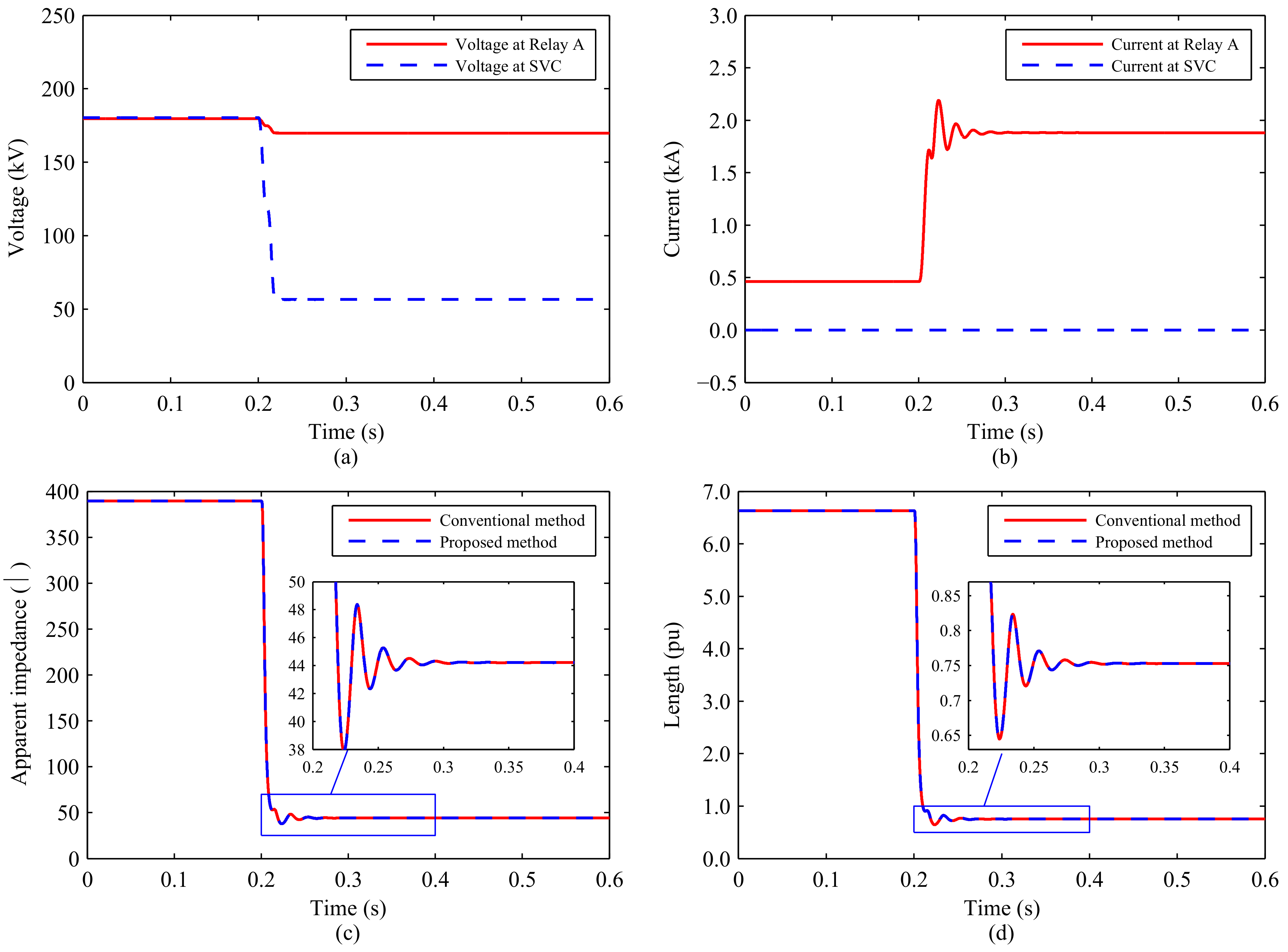
Case 2: With SVC operating at +100 Mvar Capacitive Mode..
The simulation results of Case 2 “With SVC operating at +100 Mvar capacitive mode” are shown in Figure 7. At the period of time from 0 s to 0.2 s, the system is at steady state; therefore, all measurements in this period are also normal as shown in Figure 7a–d. The simulation results in the period of Case 2 are different from Case 1. Because of the SVC operating at +100 Mvar capacitive mode, the voltage at SVC location is higher than the voltage at relay A as shown in Figure 7a. In addition, the current at SVC is about 400 A as shown in Figure 7b. The apparent impedance and fault location at the relay A in this period are shown in Figure 7c and Figure 7d, respectively.
Because the single-phase to ground fault in 150 km away from the relay A occurs at 0.2 s, the voltages at the relay A and SVC locations are reduced as shown in Figure 7a. The current at the relay A location is increased but the current at SVC is decreased as shown in Figure 7b. The apparent impedances at the relay A using both the conventional method and proposed methods are dramatically reduced when the fault occurs at 0.2 s as shown in Figure 7c. The magnification of the apparent impedance at the relay A in the period of time from 0.2 s to 0.4 s is also shown in Figure 7c. In Figure 7c, it is clear that the simulation results of the conventional and proposed method are different because the SVC is operating +100 Mvar capacitive mode. Finally, the simulation result of fault location in Figure 7d shows that the proposed method locates the fault accurately than the conventional method.
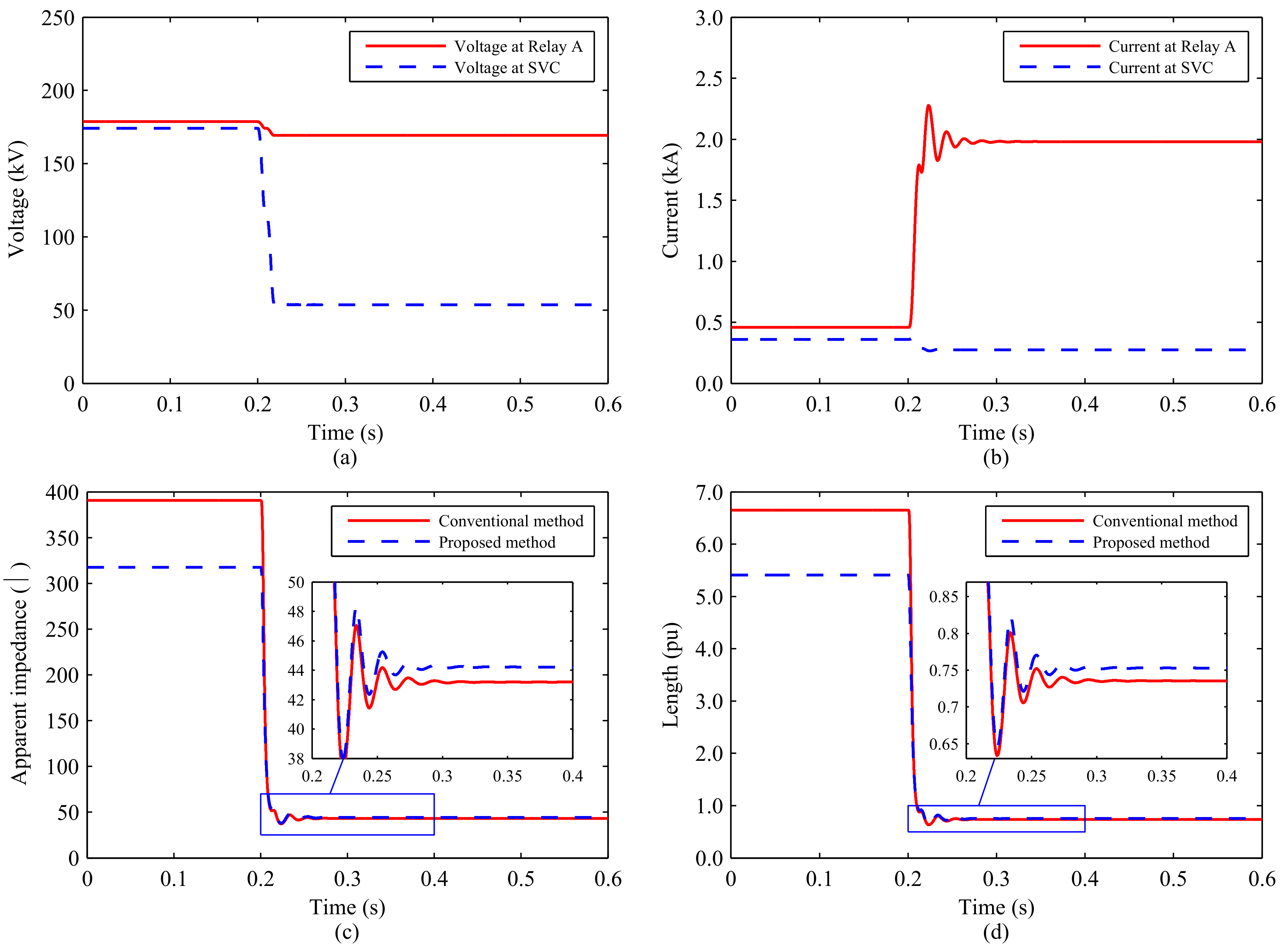
Case 3: With SVC operating at −100 Mvar inductive mode.
Figure 8 shows the simulation results of Case 3 “With SVC operating at −100 Mvar inductive mode”. At the period of time from 0 s to 0.2 s, the system is at steady state (pre-fault); therefore, all measurements in this period are also normal as shown in Figure 8a–d. It is clear that the simulation result in this period of Case 3 is also different from Case 1 and Case 2. The voltage at SVC location is lower than the voltage at the relay A as shown in Figure 8a because of the SVC operating at −100 Mvar inductive mode. Moreover, the current at SVC is about 400 A as shown in Figure 8b. The apparent impedance and fault location at the relay A in this period are shown in Figure 8c and Figure 8d, respectively.
When the single-phase to ground fault in 150 km away from the relay A occurs at 0.2 s, the voltages at the relay A and SVC locations are reduced as shown in Figure 8a, the current at the relay A location is increased but the current at SVC is decreased as shown in Figure 8b. The apparent impedances at the relay A using both the conventional method and proposed methods are dramatically reduced when the fault occurs at 0.2 s as shown in Figure 8c. The magnification of apparent impedance at the relay A in the period of time from 0.25 s to 0.6 s is also shown in Figure 8c. In Figure 8c, it is clear that the simulation results of the conventional and proposed methods are different because the SVC is operating −100 Mvar inductive mode. Finally, the simulation result of fault location in Figure 8d shows that the proposed method locates the fault accurately than the conventional method.
4. Conclusions
Based on the synchronized voltage and current measurements at the distance protection relay and SVC locations using PMUs, the proposed method in this paper has been considered as a useful approach to calculate the apparent impedance at the relay while a fault occurs in the transmission line connecting a SVC to the midpoint. The voltage and current measurements are synchronized using PMUs with GPS and are used to extract their sequence components using FFT. The new expression is used to calculate the apparent impedance at the distance relay based on the components. The simulation results show that the distance relay determines fault location and makes relay trip decisions accurately by using the proposed method. To evaluate the proposed method, the effectiveness of the fault location of the proposed method has been compared to the effectiveness of the conventional method through the simulation results. The proposed method is simple to implement for distance protection relay of transmission lines in which SVC is connected to the midpoint and operated with different modes. Finally, the main contribution of this paper is to propose a feasible method: (i) to determine the apparent impedance seen by the distance relay that only uses the voltage and current measurements synchronized using PMUs at the relay and SVC locations in the transmission line; and (ii) to make a simple method for locating faults in the power systems and improving the fault location accuracy of the conventional method.
Author Contributions
N.M.K. and D.D.T. proposed the idea and then performed the simulation in Matlab/Simulink software. N.M.K. analyzed the simulation results and wrote the paper. Finally, all the authors read and confirmed the final manuscript.
Funding
This research received no external funding.
Acknowledgments
This research was supported by Quy Nhon University, the code number of the project: T2018.569.18.
Conflicts of Interest
The authors declare no conflict of interest.
Appendix A
The Power System Parameters in Figure 1:
| Voltage source A: | |
| Nominal voltage | 220 kV |
| Phase angle | |
| Fundamental frequency | 50 Hz |
| Positive-sequence impedance | 0.8929 + j5.2088 |
| Zero-sequence impedance | 0.8929 + j5.2088 |
| Voltage source B: | |
| Nominal voltage | 220 kV |
| Phase angle | 0 |
| Fundamental frequency | 50 Hz |
| Positive-sequence impedance | 0.8929 + j5.2088 |
| Zero-sequence impedance | 0.8929 + j5.2088 |
| Transmission Line: | |
| Length | 200 km |
| positive-sequence resistance | 0.01273 /km |
| zero-sequence resistance | 0.3864 /km |
| positive-sequence inductance | 0.0009337 H/km |
| zero-sequence inductance | 0.0041264 H/km |
| SVC: | |
| Rating capacitive | ±100 Mvar |
References
- Ismail, M.M.; Hassan, M.A.M. Distance Relay Protection for Short and Long Transmission Line. In Proceedings of the 2013 5th International Conference on Modelling, Identification and Control (ICMIC), Cairo, Egypt, 31 August–2 Sepetember 2013. [Google Scholar]
- Zalitis, I.; Dolgicers, A.; Kozadajevs, J. A distance protection based on the estimation of system model parameters. In Proceedings of the IEEE Manchester PowerTech, Manchester, UK, 18–22 June 2017. [Google Scholar]
- Wydra, M. Performance and Accuracy Investigation of the Two-Step Algorithm for Power System State and Line Temperature Estimation. Energies 2018, 11, 1005. [Google Scholar] [CrossRef]
- Dai, L.V.; Tung, D.D.; Dong, T.L.T.; Quyen, L.C. Improving Power System Stability with Gramian Matrix-Based Optimal Setting of a Single Series FACTS Device: Feasibility Study in Vietnamese Power System. Complexity 2017, 2017. [Google Scholar] [CrossRef]
- Albasri, F.A.; Sidhu, T.S.; Varma, R.K. Impact of Shunt-FACTS on Distance Protection of Transmission Lines. In Proceedings of the Power Systems Conference: Advanced Metering, Protection, Control, Communication, and Distributed Resources, Clemson, SC, USA, 14–17 March 2006. [Google Scholar]
- Ghorbani, A.; Mozafari, B.; Khederzadeh, M. Impact of SVC on the protection of transmission lines. Int. J. Electr. Power Energy Syst. 2012, 42, 702–709. [Google Scholar] [CrossRef]
- Khoa, N.M.; Hieu, N.H.; Viet, D.T. A Study of SVC’s Impact Simulation and Analysis for Distance Protection Relay on Transmission Lines. Int. J. Electr. Comput. Eng. 2017, 7, 1686–1695. [Google Scholar] [CrossRef]
- Henna, M.Y.E.; Nagy, S.A. Prevention of Cascaded Events of Distance Relay Zone Three Using Logic Controls, In Proceedings of the International Conference on Electrical and Computer Engineering, Benghazi, Libya, 26–28 March 2013.
- Singh, S.T.; Rajiv, K.V. Performance of distance relays on shunt-FACTS compensated transmission lines. IEEE Trans. Power Deliv. 2005, 20, 1837–1845. [Google Scholar] [CrossRef]
- Kazemi, A.; Jamali, S.; Shateri, H. Measured Impedance by Distance Relay in Presence of SVC on Transmission Line. Int. Rev. Electr. Eng. 2006, 5, 2214–2219. [Google Scholar] [CrossRef]
- Albasri, F.A.; Sidhu, T.S.; Varma, R.K. Performance comparison of distance protection schemes for shunt-FACTS compensated transmission lines. IEEE Trans. Power Deliv. 2007, 22, 2116–2125. [Google Scholar] [CrossRef]
- Khederzadeh, M.; Ghorbani, A. STATCOM modeling impacts on performance evaluation of distance protection of transmission lines. Eur. Trans. Electr. Power 2011, 21, 2063–2079. [Google Scholar] [CrossRef]
- Thakre, M.P.; Kale, V.S. An adaptive approach for three zone operation of digital distance relay with static var compensator using PMU. Int. J. Electr. Power Energy Syst. 2016, 77, 327–336. [Google Scholar] [CrossRef]
- Dubey, R.; Samantaray, S.R.; Panigrahi, B.K. Adaptive distance protection scheme for shunt-FACTS compensated line connecting wind farm. IET Gener. Trans. Distrib. 2016, 10, 247–256. [Google Scholar] [CrossRef]
- Biswal, S.; Biswal, M. Adaptive distance relay algorithm for shunt compensated transmission line. In Proceedings of the International Conference on Electrical Power and Energy Systems (ICEPES), Bhopal, India, 14–16 December 2016. [Google Scholar]
- Sree, Y.M.; Kumar, G.R.; Vaidehi, M.; Priya, G.V. Wavelet approach for transient current based multi terminal transmission system protection scheme in the presence of SVC. In Proceedings of the International Conference on Electrical, Electronics, and Optimization Techniques, Chennai, India, 3–5 March 2016. [Google Scholar]
- Albasri, F.A.; Sidhu, T.S.; Varma, R.K. Mitigation of Adverse Effects of Midpoint Shunt-FACTS Compensated Transmission Lines on Distance Protection Schemes. In Proceedings of the Power Engineering Society General Meeting, Tampa, FL, USA, 24–28 June 2007. [Google Scholar]
- Azriyenni, A.; Mustafa, M.W. Application of ANFIS for Distance Relay Protection in Transmission Line. Int. J. Electr. Comput. Eng. 2015, 5, 1311–1318. [Google Scholar] [CrossRef]
- Teng, Y.; Li, X.; Huang, Q.; Wang, Y.; Jing, S.; Jiang, Z.; Zhen, W. A Novel High-Frequency Voltage Standing-Wave Ratio-Based Grounding Electrode Line Fault Supervision in Ultra-High Voltage DC Transmission Systems. Energies 2017, 10, 309. [Google Scholar] [CrossRef]
- Liu, Y.; Xie, X.; Hu, Y.; Qian, Y.; Sheng, G.; Jiang, X. A Novel Transient Fault Current Sensor Based on the PCB Rogowski Coil for Overhead Transmission Lines. Sensors 2016, 16, 742. [Google Scholar] [CrossRef] [PubMed]
- Mandava, S.; Vanishree, J.; Ramesh, V. A Spanning Tree Approach in Placing Multi-channel and Minimum Channel PMU’s for Power System Observability. Int. J. Electr. Comput. Eng. 2015, 5, 518–524. [Google Scholar] [CrossRef]
- Ghorbani, A.; Soleymani, S.; Mozafari, B. A PMU-based LOE protection of synchronous generator in the presence of GIPFC. IEEE Trans. Power Deliv. 2016, 31, 551–558. [Google Scholar] [CrossRef]
- Yin, H.; Fan, L. PMU Data-Based Fault Location Techniques. In Proceedings of the North American Power Symposium, Arlington, TX, USA, 26–28 September 2010. [Google Scholar]
- Zeinhom, A.N. Phasor measurement unit-based distance protection and fault location algorithm for series-compensated transmission lines. In Proceedings of the Saudi Arabia Smart Grid Conference (SASG), Jeddah, Saudi Arabia, 14–17 December 2014. [Google Scholar]
- Zhang, T.; Wang, F.; Fu, W. Fault Detection and Isolation for Redundant Inertial Measurement Unit under Quantization. Appl. Sci. 2018, 8, 865. [Google Scholar] [CrossRef]
- Khebbache, H.; Labiod, S.; Tadjine, M. Adaptive sensor fault-tolerant control for a class of multi-input multi-output nonlinear systems: Adaptive first-order filter-based dynamic surface control approach. ISA Transac. 2018. [Google Scholar] [CrossRef] [PubMed]
- Al-Mohammed, A.H.; Abido, M.A. Fault Location Based on Synchronized Measurements: A Comprehensive Survey. Sci. World J. 2014, 2014. [Google Scholar] [CrossRef] [PubMed]
- Ghorbani, A.; Ebrahimi, S.Y.; Ghorbani, M. Active power based distance protection scheme in the presence of series compensators. Prot. Control Modern Power Syst. 2017, 2. [Google Scholar] [CrossRef]
Figure 1.
The one-line diagram of the study power system.
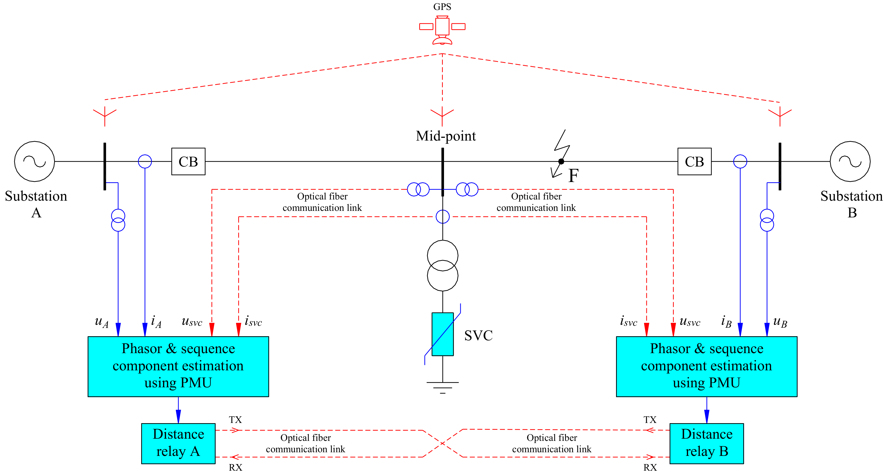
Figure 2.
(a) sinusoidal waveform; (b) phasor representation.

Figure 3.
Schematic diagram of a phasor measurement unit (PMU) connected to the power system.

Figure 4.
The sequence networks. (a) the positive sequence network; (b) the negative sequence network; (c) the zero sequence network.
Figure 4.
The sequence networks. (a) the positive sequence network; (b) the negative sequence network; (c) the zero sequence network.
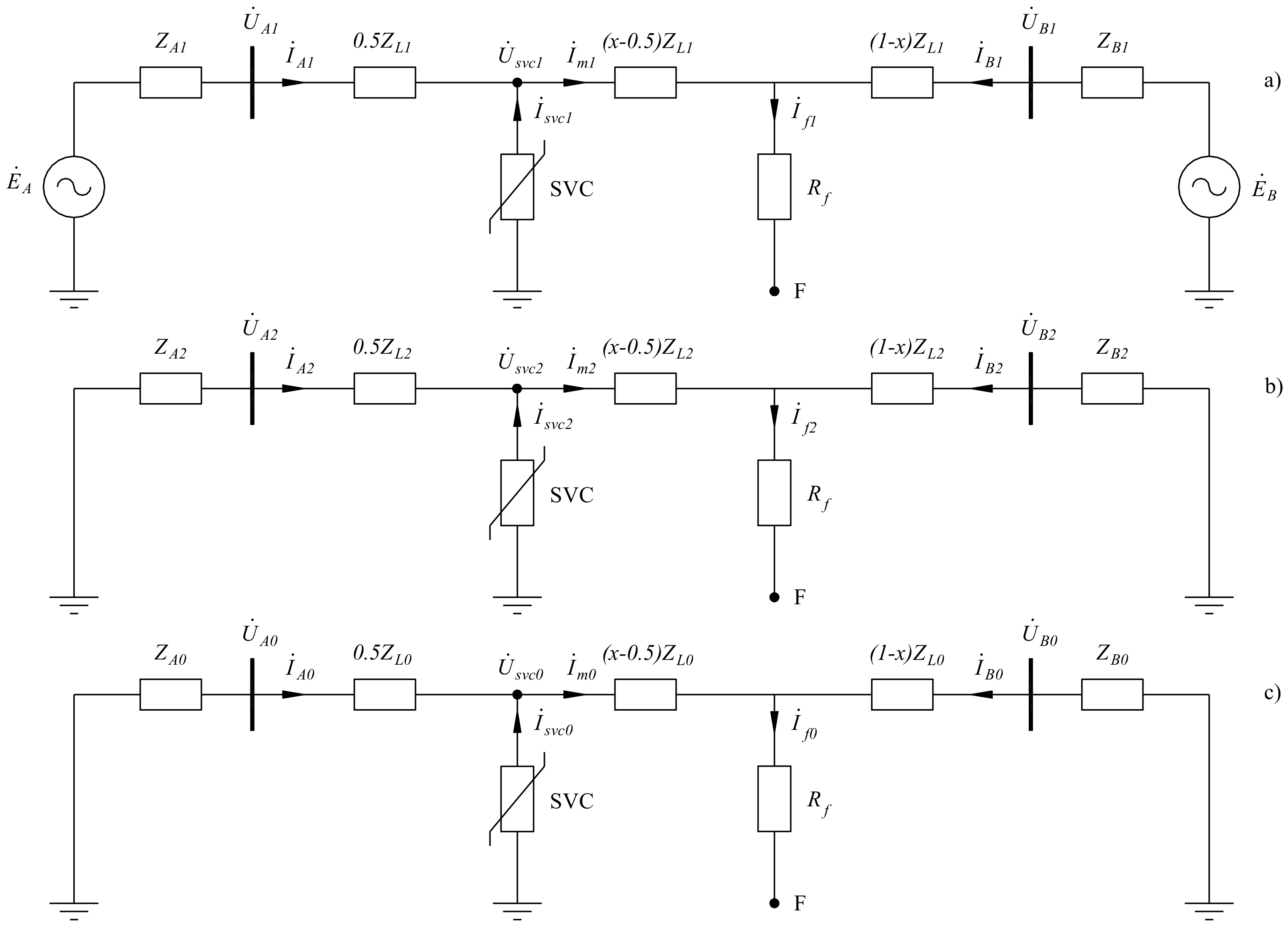
Figure 5.
The proposed algorithm for locating fault in transmission line with a SVC.

Figure 6.
The simulation results of Case 1. (a) voltage measurement; (b) current measurement; (c) apparent impedance at relay A; (d) fault location.
Figure 6.
The simulation results of Case 1. (a) voltage measurement; (b) current measurement; (c) apparent impedance at relay A; (d) fault location.

Figure 7.
The simulation results of Case 2. (a) voltage measurement; (b) current measurement; (c) apparent impedance at relay A; (d) fault location.
Figure 7.
The simulation results of Case 2. (a) voltage measurement; (b) current measurement; (c) apparent impedance at relay A; (d) fault location.
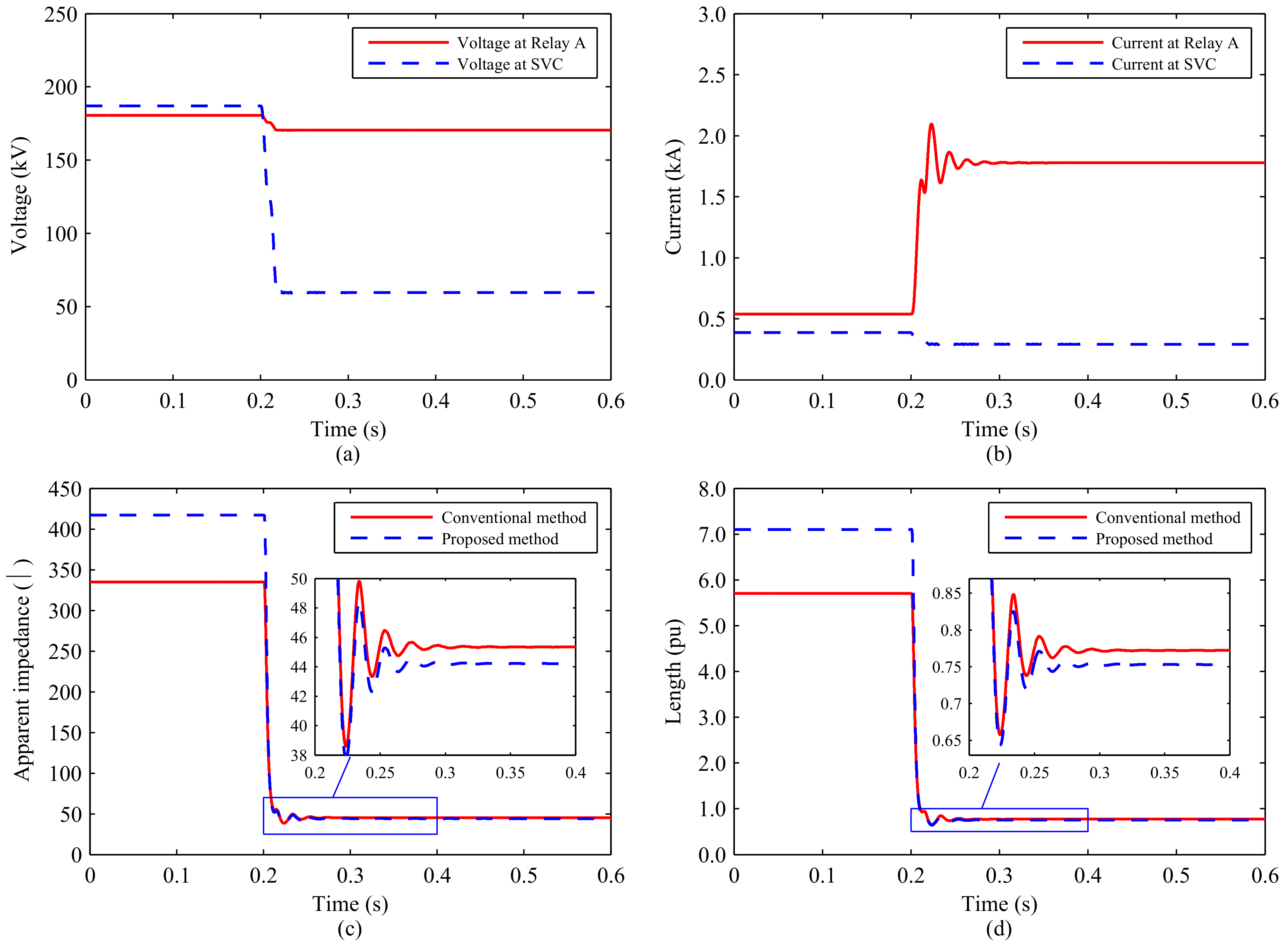
Figure 8.
The simulation results of Case 2. (a) voltage measurement; (b) current measurement; (c) apparent impedance at relay A; (d) fault location.
Figure 8.
The simulation results of Case 2. (a) voltage measurement; (b) current measurement; (c) apparent impedance at relay A; (d) fault location.
© 2018 by the authors. Licensee MDPI, Basel, Switzerland. This article is an open access article distributed under the terms and conditions of the Creative Commons Attribution (CC BY) license (http://creativecommons.org/licenses/by/4.0/).
Share and Cite
MDPI and ACS Style
Khoa, N.M.; Tung, D.D. Locating Fault on Transmission Line with Static Var Compensator Based on Phasor Measurement Unit. Energies 2018, 11, 2380. https://doi.org/10.3390/en11092380
AMA Style
Khoa NM, Tung DD. Locating Fault on Transmission Line with Static Var Compensator Based on Phasor Measurement Unit. Energies. 2018; 11(9):2380. https://doi.org/10.3390/en11092380
Chicago/Turabian StyleKhoa, Ngo Minh, and Doan Duc Tung. 2018. "Locating Fault on Transmission Line with Static Var Compensator Based on Phasor Measurement Unit" Energies 11, no. 9: 2380. https://doi.org/10.3390/en11092380
Note that from the first issue of 2016, this journal uses article numbers instead of page numbers. See further details here.