Theoretical and Experimental Contributions on the Use of Smart Composite Materials in the Construction of Civil Buildings with Low Energy Consumption


1
Faculty of Engineering and Management of Technological Systems, Politehnica University of Bucharest, 060042 Bucharest, Romania
2
Faculty of Engineering, Lucian Blaga University of Sibiu, 550024 Sibiu, Romania
*
Author to whom correspondence should be addressed.
Energies 2018, 11(9), 2310; https://doi.org/10.3390/en11092310
Submission received: 24 July 2018
/
Revised: 17 August 2018
/
Accepted: 30 August 2018
/
Published: 2 September 2018
(This article belongs to the Special Issue Building Energy Use: Modeling and Analysis)
Abstract
:The paper presents the theoretical and experimental studies undertaken for the realization of an intelligent composite material with phase shift that has optimal characteristics in the thermal energy storage process and an experimental method for integrating the material with phase change in a possible efficient system to be used in the construction of a dwelling. It analyzes the main factors in designing such systems (the temperature limits between which the system must operate, the melting/solidification temperature of the Phase Change Material (PCM), the latent heat of the PCM, the degree of thermal loading, the bed configuration of PCM capsules and a PCM-RB01 material is set. A micro-encapsulation method was chosen and a “solar wall” is made where the incident solar radiation is absorbed by the PCM embedded in the wall, so the stored heat is used for heating and ventilation of a home. Experimental research has shown that developed PCM allows a maximum room temperature reduction of about 4 °C during the day and can reduce the night-time heating load. Also, despite the lower thermal energy absorption capacity, the developed PCM-RB01 material provides a superior physical stability compared to the classical types of integration.
1. Introduction
With the onset of the global energy crisis, energy consumption has become a vital issue and its conservation has become of paramount importance. Thus, reducing the energy consumption of dwellings by improving their manufacturing technology became a particularly important opportunity. Of all forms of energy consumed in a home, most is allocated to heating or cooling indoor air. Thus, energy consumption can be substantially reduced if passive energy storage technologies are incorporated at the design stage of the dwelling. This concept of passive storage of energy in order to obtain thermal comfort is of real interest worldwide with the main purpose of reducing energy consumption [1,2,3,4].
Direct energy gains are direct energy consumption and are typically attributed to heating needs. Indirect gains that are absorbed and stored in the buffer area are used to reduce temperature differences between the inner and outer environments. Three general types of problems can occur in solar energy storage systems: insufficient storage temperature mass, considerable temperature changes in the storage environment, and issues related to the phase-out between energy gain and demand periods. These problems can be solved or attenuated by modifying the thermal properties of the building material using latent heat as an energy storage mode. In the field of passive (classical) technologies, the calorific capacity of building elements is one of the most important features. Such traditional storage systems that exclusively use the calorific capacity of materials give rise to several problems: high cost, excessive mass and undesirable temperature fluctuations. Therefore, the research, carried out in this paper, addresses these problems with the proposed use of traditional building materials in combination with phase change materials (latent phase change heat). With these materials, the additional latent heat is used to increase the capacity of thermal elements of the building elements. In addition, the phase change is isothermal, providing an excellent means of temperature control [5,6,7,8].
Considering the importance of reducing the costs of acclimatization of buildings, the researches included in this paper have proposed to achieve the following objectives [9,10,11]: determining the phase change materials with an optimal applicability in the storage of thermal energy; determining an experimental method of integration of materials with phase change in the realization of a smart composite material; characterizing the process of material integration with phase change in the final composite material.
Characteristics of phase change materials (PCM) enable optimal storage of thermic energy in the use of latent heat. Specialty literature highlights several types of phase-change materials, but the most studied are organic PCMs and inorganic PCMs. The thermal energy absorption process at the level of building walls causes PCM to melt, and when the ambient temperature decreases, a recrystallization is achieved to achieve a stabilization of the building's interior temperature. Thus, the use of PCMs ensures temperature stabilization inside buildings, and this is possible through reversible and repeatable phase changes [11,12].
Conservation of energy in buildings and cars is favored by the storage of thermal energy that can be achieved by using PCMs with polymers in pairs of immiscible mixtures, favored by the miscibility of the mixture, which can exert a positive influence on the energy efficiency of buildings [13,14]. Phase changes of PCMs in the process of transformation from solid to liquid (when energy is absorbed) and liquid-to-solid crystallization (when energy is released) provide stabilization of the interior temperature of buildings. The practical use of these types of materials is limited by the leakage of PCMs [15]
Spills can be reduced by applying different techniques between macro and micro-encapsulation, immersion and direct incorporation. Research to date has revealed the possibility of using skeletal materials with higher melting temperature compared to PCMs. Thus, polyethylene (PE) can be used as a sealant to reduce paraffin leakage [16]. The use of solvent baths is a rigorous test to determine the interconnectivity of the paraffin phase [17]. Paraffin spills were found to be significantly influenced by PEG molecular weight, fiber volume fraction, PCM surface energy except wood flour treatment. Also, by decreasing the volume fraction of fibers and increasing PCM viscosity, a significant reduction in leakage reduction can be achieved. Research by using a ternary composite and a binary composite with the same amount of paraffin showed that the binary composite exhibited a faster leakage than the ternary composite [18].
PCMs could play an important role in the efficient and economical use of thermal energy in the industrial sector (e.g., waste heat recovery, storage and reuse) as well as in electricity generation based on new techniques conversion (e.g., co-generation) and renewable energy (e.g., solar concentrating technologies). Moreover, PCM integration in buildings is expected to be a useful and good way to reduce indoor temperature variations and reduce global warming by reducing energy consumption of climate control. The most important property of PCM is their ability to store or release heat in a small temperature range as well as the presence of a latent heat of 100 ... 1000 kJ/kg for solid-liquid or liquid-solid transformation [19,20].
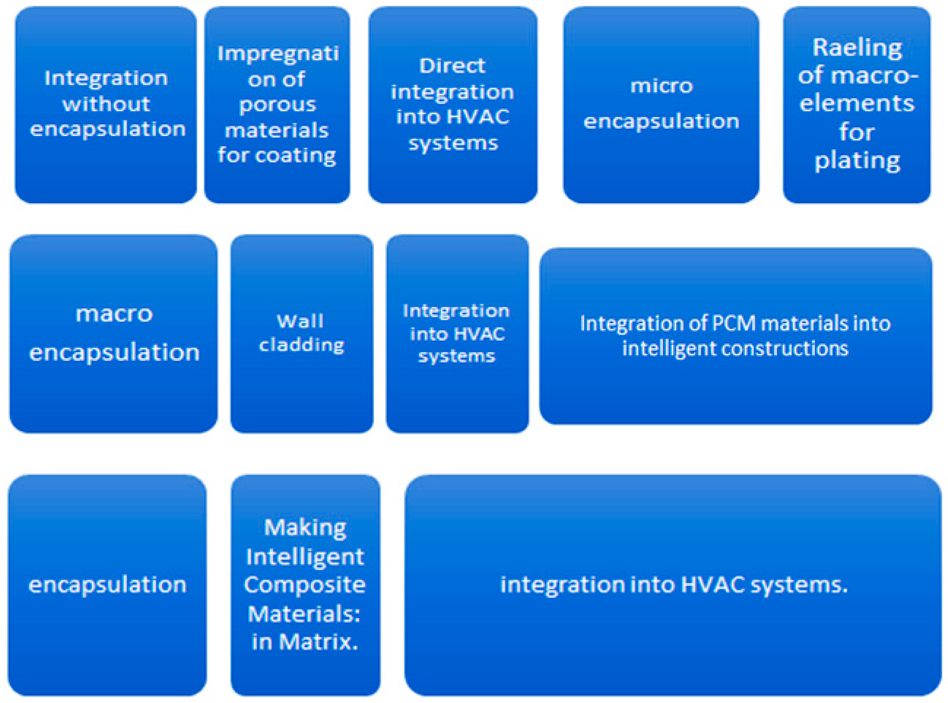
Thus, a method of storing energy in walls, ceilings and floors of a building can be obtained by encapsulating phase-shifting materials to capture direct solar energy and increase human comfort by decreasing the internal temperature variation of the air, keeping the temperature closer to the desired value for a longer period of time [21,22,23,24]. Such an ideal PCM material has to meet a number of criteria: have high value of latent heat due to phase change, good thermal conductivity, high calorific value, and low volume change, and be non-corrosive, non-toxic, and cyclic over time. A classification of the main integration methods developed so far is presented in Figure 1.
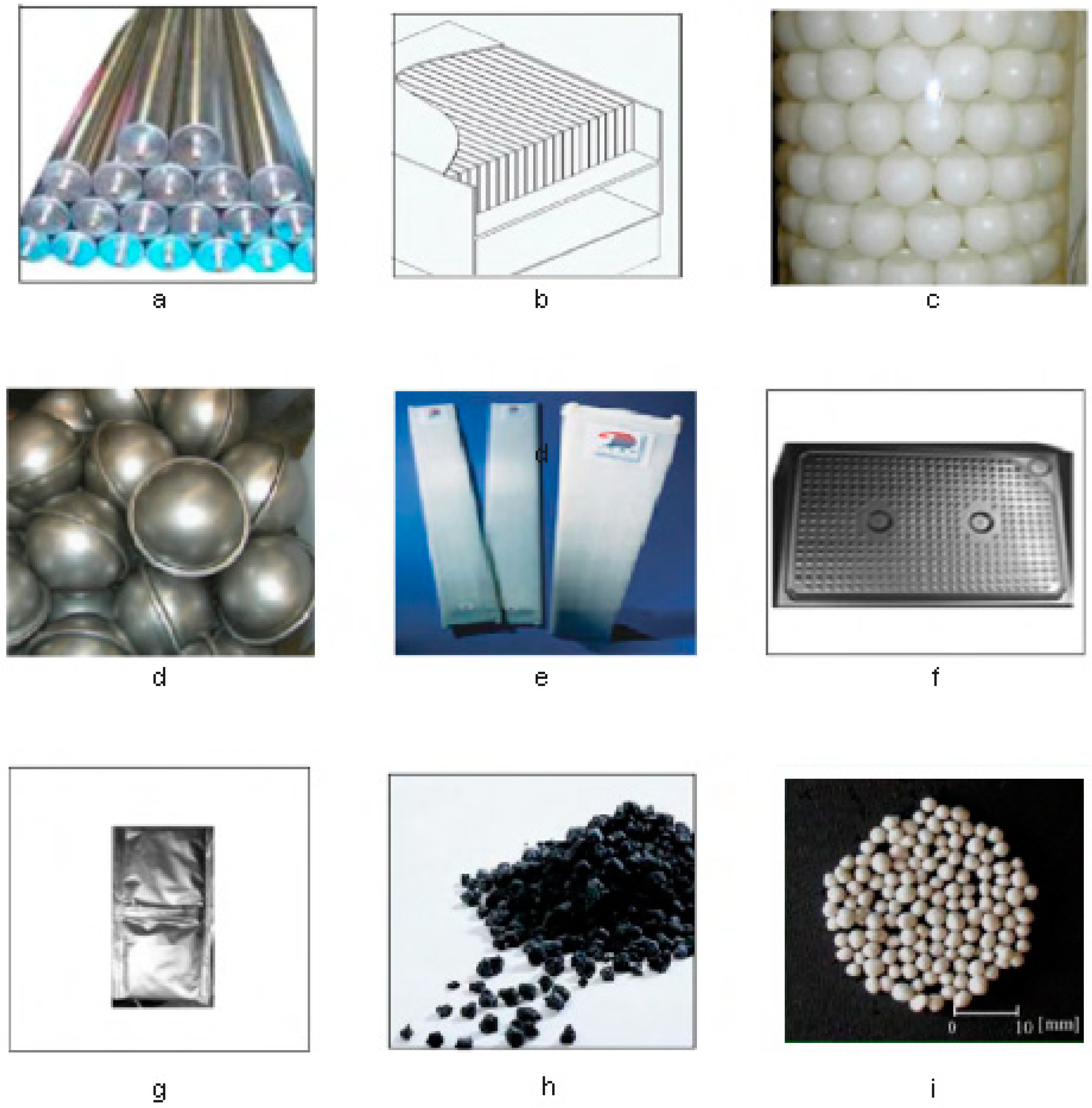
Due to the two states, the liquid state and the solid state, the use of phase change materials requires a retention method in the construction. The most developed method of retaining is that of encapsulation distinguishing two main variants: micro-and macro-encapsulation. In micro-encapsulation, small particles of spherical or rod shaped PCM are encapsulated in a thin film. The resulting particles can then be incorporated into any matrix that is compatible with the encapsulation film. One of the main conditions of this encapsulation method is the PCM compatibility—the capsule material—the final composite matrix. Macro-encapsulation represents the inclusion of the PCM in some type of package (tubes, bags, spheres, panels or other containers) as shown in Figure 2. These “containers” can serve directly as heat exchangers or can be incorporated into construction products [25,26,27,28].
In the case of a civil construction, thermal transfer through the walls is achieved by thermal conduction. The exterior and interior heat transfer process is carried by convection and radiation. A general representation of the transfer phenomena is shown in Figure 3.
The use of PCM materials ensures a reduction of indoor fluctuations by heat storage in the form of phase change and brings a maximum benefit when applied to lightweight buildings because they have an intrinsically low storage capacity, and achieve a high tier of efficiency due to:
- a small energy exchange with the exterior, ensured by thermal insulation;
- the use of renewable energy sources;
- reducing energy requirements by using phase change materials.
In practice, several energy storage systems TES (Thermal energy storage) are used, but the most technically important is the LHTES (latent heat thermal energy storage). In case of LHTES heat storage there are two more technical problems, namely the lower thermal conductivity of the phase-change materials and the corrosion manifested in the material of the storage vessel. A possible technical solution that can be applied to solve these problems is Macro-encapsulation that maximizes the heat transfer area as well as reducing contact between PCMs and storage vessels. However, a difficult problem is to identify a Macro-encapsulation technique that would allow the two aspects to be addressed [29].
Although in practice there are several techniques to achieve integrated heat storage systems, they all rely on the energy storage capacity. Under these conditions, phase changing materials (PCMs) allow the storage of heat that can be used later on depending on energy consumption [30].
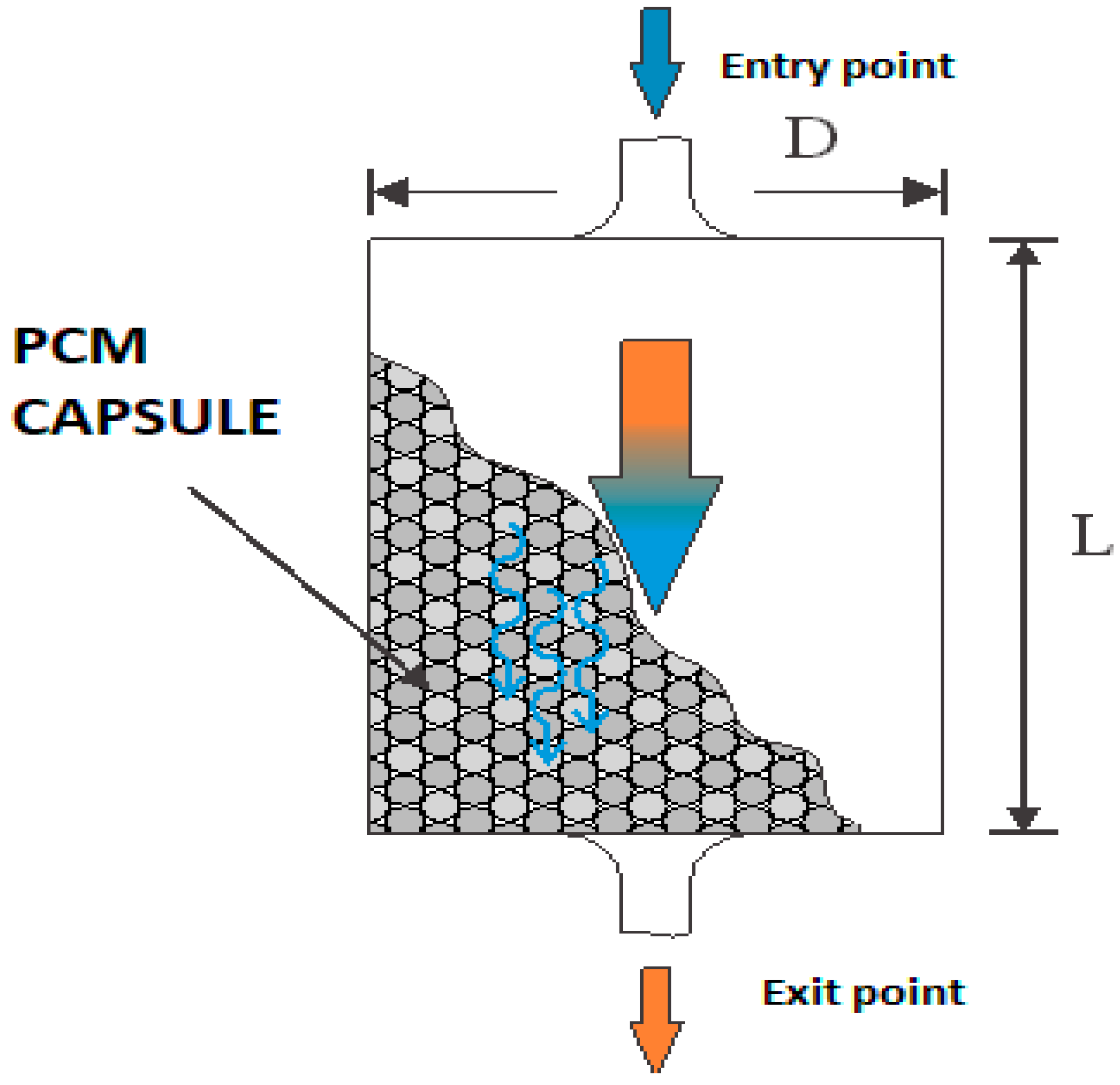
Research in the field has shown the feasibility of integrating PCM macro-capsules into acclimatization systems. Such systems use the ability of PCM to store energy by changing the phase for storage of thermal energy. The scheme of the thermal energy storage system with PCM macro-capsules is shown in Figure 4. The main factors to consider in designing such systems are: the temperature limits in which the system must work; the melting/solidification temperature of the PCM material; the latent heat of PCM material; the degree of thermal loading; and the PCM capsule bed configuration [31,32,33].
Considering the importance of reducing the costs related to ensuring the energy efficiency of buildings, the researches included in this paper have aimed to achieve the following objectives:
- -
- determination of new materials with phase change, that can be used in thermal insulation of buildings to increase the energy efficiency of them;
- -
- identifying a technologies of integration of materials with phase change in order to achieve an intelligent composite material;
- -
- establishing the energy efficiency offered by intelligent composite material.
The research carried out mainly focused both a mathematical modeling of the heat transfer phenomenon as well as an experimental part which aims to establish some technologies of obtaining composite materials with phase change. It is also very important to establish the conditions in which emulsification is performed to obtain butyl stearate particles as efficient as possible.
Thus, in a first phase, a series of experimental researches were carried out, by which the technological process of obtaining the composite material with phase transformation was optimized. In order to obtain a thermally as efficient as possible intelligent composite material, a thermal analysis of the microcapsules, as well as of the matrix composites with cement respectively gypsum, in which the microcapsules are incorporated, was performed.
2. Materials and Methods
2.1. Experimental Realization of Intelligent Composite Material with Phase Change
The research contained in this paper came from the desire to create a smart composite material with the ability to improve the thermal properties of buildings. Phase change materials have been identified as being the best candidates for making a composite material capable of meeting the thermal needs. From the multitude of PCM materials, we chose butyl stearate because it best responds to the required parameters: 19 °C melting/solidification temperature, appropriate to the climate in Romania; its abundance and low cost; and the large amount of energy stored at the change of phase.
Butyl stearate, MMA and allyl-MMA were obtained from Sigma Aldrich via REDOX S.R.L. (Taufkirchn, Germany). Azobisisobutyronitrile (AZDN) as polymerization initiator was obtained from ARKEMA Inc. (King of Prusia, PA, USA), and the Pluronic PE6200 surfactant was obtained from BASF. Iron sulphate (FeSO4-7H2O), ammonium persulfate, and sodium thiosulfate (NaS2O7) were obtained from various Romanian producers and were used without further purification. For the use of butyl stearate to be successful, developing a method of retaining butyl stearate in the intelligent composite material was necessary. Thus the microencapsulation process by complex coacervation of methyl butyrate stearate in the methyl polymethacrylate membrane was developed. Butyl microcapsules stearate-PMMA were prepared using a polymerization emulsion with the complex coacervation process. Additionally, tests were performed to determine the rheological properties of the emulsions in order to determine their stability over time as well as to determine the experimental reproducibility of the characteristics.
The preparation of butyl stearate/PMMA microcapsules was performed using a mini-emulsion apparatus. In the reaction vessel, the following substances were mixed for half an hour to obtain the first EM1 emulsion: 100 mL of deionized water, 25 g of butyl stearate and 2 g of Pluronic PE6200 (Surfactant). The above mixture was made at a temperature of 30 °C, above the melting point of butyl stearate. Then 25 mL of MMA, 2.5 g of allyl-MMA, 1 mL of freshly prepared solution of FeSO4-7H2O (0.3 g of FeSO4-7H2O in 200 mL of water) and 0.25 g of persulfate of ammonium were added. The addition of allyl-MMA as a reticular agent during polymerization prevented the formation of secondary particles, thereby producing microcapsules of equal size and shape. Also, the addition of a secondary initiator during the polymerization produced uniform microcapsules and gives a high yield without a subsequent process. The resulting solution was vigorously mixed at 2000 rpm for 30 min, thereby obtaining the emulsion. In the last step 0.25 g of Na2S2O7 and 1.00 g of AZDN were added and the mixing process was continued for one hour. At the end of the mixing, a white precipitate was obtained representing the butyl-PMMA stearate microcapsules. After a relaxation time of 30 min, the precipitate was separated from water and subsequently dried under vacuum at ambient temperature for 24 h. The steps and times required for making butyl stearate microcapsules are shown in Table 1.
In order to determine the rheological properties, a large number of experiments were carried out to determine both the stability of the emulsions and the repeatability of the obtained results.
For the determination of rheological properties, a Physica MCR 301 rheometer manufactured by Anton Paar (Ashland, VA, USA) was used. The MCR 301 rheometer is a high-complexity device that meets the most demanding measurement requirements.
Rheological testing was performed on the intermediate emulsions of the microencapsulation process of butyl stearate. Thus, during the experiments, samples were taken from the key steps presented in Table 1, and the tests were performed at angular speeds of ω = 1 rad/s respectively, ω = 10 rad/s.
From the researches conducted, it was observed that the first emulsification (Table 1—Water, Butyl Stearate, Pluronic PE6200), which lasts 30 min, has of the highest importance for obtaining the best microcapsules of butyl stearate. The determination of the rheological properties of this emulsion time was aimed at determining the dynamic viscosity n*, the elastic modulus G' and the viscous modulus G''. The determination of the rheological properties was done for a period of 70 min at 24 h after the emulsification.
For each determination, similar results as shown in Figure 5 were obtained, where it is observed that for the same emulsion, the elastic modulus is higher than the viscous modulus throughout the measurement. There is a significant increase in the elastic and viscous module and in the complex viscosity at about one hour from the start of the measurement. Testing for butyl stearate shows a complex viscosity nine times greater than that of water, the viscous module being 10 times greater than the elastic modulus, and all three dimensions are approximately constant during the measurement.
It is also evident from Figure 5 that for the same emulsion, the elastic modulus is higher than the viscous modulus throughout the measurement. This change is due to the 24 h of rest and therefore due to the completion of the polymerization process.
After the three emulsificatios and vacuum drying, a material in a white powder form, with a grain size of 0.5–3 mm was formed, and the constituent granules presented a high friability (Figure 6).
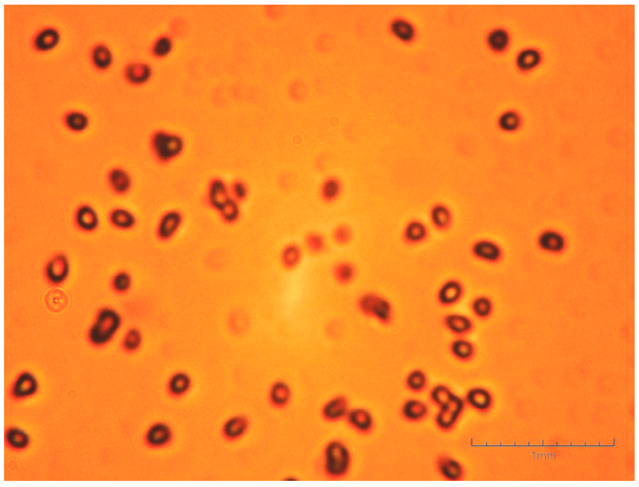
Microscopic images of PMMA-stearate microcapsules, 100× magnification are shown in Figure 7.
2.2. The Theoretical Contributions on the Mathematical Model of Heat Transfer through the Proposed Composite Intelligent Composite Material to Be Achieved
The mathematically analyzed composite material is matrix-spherical particle type. The idealized model is an isotropic matrix with thermal transfer coefficients, density and constant caloric capacity.
This initial hypothesis on the isotropy of the properties of matrix composite material was made in order to achieve a mathematical modeling of the heat transfer process through the phase-change composite material. In practice, the isotropy of the properties of the matrix material composite is almost impossible, but the mathematical model obtained in the case of the ideal matrix is just a starting point for analyzing the matrix properties of composite material. Thus, the difference between the real material properties determined experimentally and those of the ideal isotropic material determined by mathematical modeling, gives us important information regarding the isotropy of the real material. Under these conditions, obtaining a mathematical model of heat transfer through the phase shift intelligent composite material is of particular importance both in the experimental research phase as well as in the analysis stage of the real material properties.
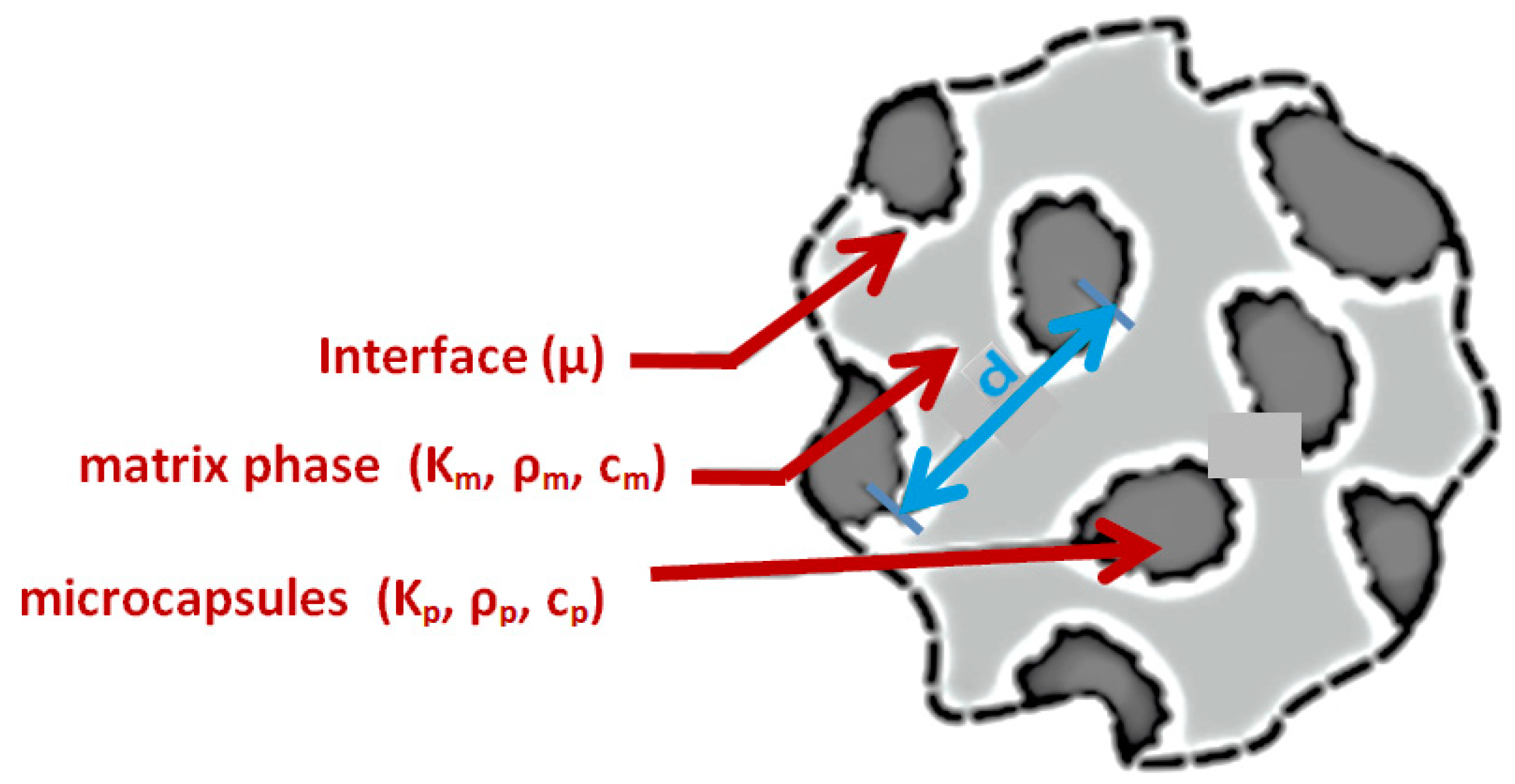
Particles embedded in the matrix are also considered to have thermal transfer coefficients, density and constant calorific capacity. The derivation of the mathematical model involves defining conductivity at the μ interface. The contact surface and conductivity at this interface is what separates the spherical particle from the surrounding matrix. A section of the composite material made, type PCM-RB01, is shown in Figure 8.
To define conductivity at the interface, the Fourier law is applied to model the normal component of the heat flux across the interface so that heat flux is proportional to the temperature difference between the two media. If it is assumed that each particle is completely covered by the matrix phase, then the heat flux to the particle in the radial direction can be described by Equation (1) [14]:
where: is the thermal conductivity at the surface; Tm—matrix temperature in °K; Tp—the temperature of the microcapsule in °K.
In order to make subsequent calculations, the following assumptions are made:
where: is the total volume of the composite; —particle volume; Vm—matrix volume; vp—the volume of a particle; np—number of particles.
The constitutive equations of the heat transfer are given the system of equations:
Starting from the general equation of energy given by the relationship:
which by simplification leads to the expression:
or to an even simpler expression of the form:
For the next step the notations are made: Q is the thermal energy entering the composite particles, ap—the surface of the particle sphere and qm is the flow of thermal energy entering the pail. By multiplying Q with the total number of composite particles, is obtained the total energy transfer rate at the matrix exit through contact at the surface of the spheres is indicated by Sc. By introducing Equations (9) to (11) is the result Equation (12). For the next step, an element is defined in a Cartesian coordinate system with the dimensions Δx, Δy and Δz. Thus, the integral of Equation (1) is represented by Equation (13). The evaluation of integers is presented in Equation (15):
For the continuation of the calculations, the following approximation is made: at the intersection of a plane with the volume of the composite, the area represented by the matrix phase is equal to the fraction in the total area of the intersection. After this approximation the equality (16) is reached and after rearrangement leads to (16), respectively to Equation (17). Equation (17) is rewritten in a more compact way resulting in Equation (18):
Equation (18) is further written in a simpler way:
By substituting (17) and (9) into (11) there is obtained (18) and by (2) substitution in (18) obtaining (19). Dividing (19) with (4) and applying the expression limit when Vm→∞ is obtained (20). The relation between the area and the volume of a sphere is given by (24). Introducing this expression into (22) results (24). Using the relations (4)–(6), the expression (24) can be simplified (25). By grouping all constants, conductivity, density, calorific capacity in a single constant , the expression can be simplified (26). Substituting (5) into (26) is finally obtained (28):
The resulting equation is called the thermal diffusivity of the matrix according to two variables Tp (R) and Tm for space x and time t [34,35].
Also, for measuring the thermal properties of the intelligent composite material it is necessary to establish a procedure for their calculation. This procedure has the role of eliminating the need for similar calculation sections by testing methods, begging possible to obtain a series of calculation formulas that will represent the standard as a reference. The properties of the thermal transmission described include: thermal conductivity, thermal resistance, apparent thermal conductivity apparent thermal resistivity. This procedure also provides a method for obtaining the apparent thermal conductivity depending on the temperature for the material measured for different temperature differences. So, the apparent thermal conductivity was defined by the relationship:
and apparent thermal resistivity ra, given by the relationship:
where: is apparent thermal resistivity, in K m/K; L—the thickness of a board in the direction of the heat transfer, in m; Tc—air temperature in the weighted area of cold surface model, in degrees °K; Th—air temperature in the weighted area of the warm surface model, in degrees °K; Q—the amount of energy input into the system, in W; A—the surface aria, in m2.
The apparent thermal resistivity and the corresponding thermal conductivity are reciprocal, and these terms apply to the specific materials tested between two isothermal surfaces specified. For this method, the materials are considered to be homogeneous when the value and thermal conductivity or thermal resistivity are not significantly affected by variations in thickness or the area of the sample, in the used interval normally by these variables.
Thermal resistance at the cold surface interface Rc and thermal resistance at the warm surface interface Rh represents the amount of heat determined by the temperature difference in the state of equilibrium between an isothermal surface and the air around it, and they provide information on the heat flow per unit of the surface. Usually, this parameter includes the combined effects by conduction, convection, and radiation. Thermal resistance at the warm surface interface Rh is calculated with the relationship:
Thermal resistance at the interface with cold surface Rc is calculated with the relationship:
where: T1 is the air temperature in the warm zone; T2—air temperature in the cold zone.
The heat transfer coefficient at the interface the with warm surface hh is calculated with the relationship:
The heat transfer coefficient at the interface the with cold surface hc is calculated with the relationship:
The heat transfer coefficients at interface with warm and cold surface and the resistance of the cold or warm thermal surface are reciprocal. All these properties are set for a specific set of environmental conditions.
Thus, the total thermal resistance Rt was defined as:
The thermal conductivity λ, is given by the relation:
where: ΔT is the average of the temperature difference between the two interfaces.
All these Equations (29)–(36) can be used efficiently for the theoretical calculation of the thermal properties of the intelligent composite material and the comparison of the results with those obtained in the experimental research.
3. Results and Discussion
The experimental researches focused on the thermal behavior of phase shift intelligent composite materials, which have in the structure microcapsules of butyl stearate. For making composite material, cement and gypsum were used as matrix. The choice of the two materials was made considering that they are used very often at the building the walls of the buildings.
3.1. Characterization of Thermal Behavior of Composite Material Made of Cement Matrix and PCM-RB01 Butyl Stearate Microcapsules
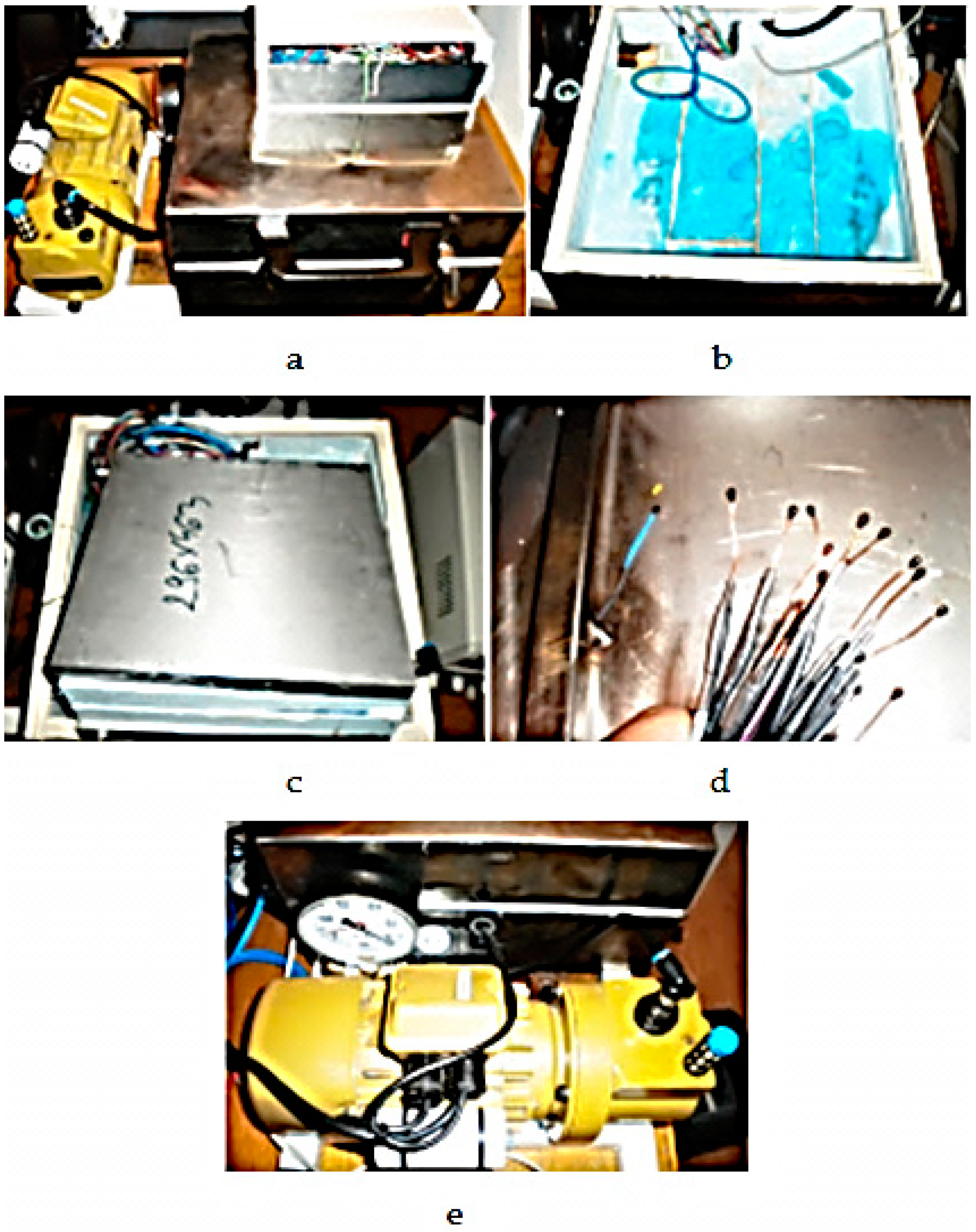
In order to establish thermal properties a GHP-RB01 experimental model stand has been designed and built (Figure 9a), which consists of a measuring enclosure (Figure 9b), a vacuum pump (Figure 9e) and two programmable current sources. The measuring enclosure was 90 × 350 × 350 mm in size and was made of 308L stainless steel with a 2 mm sheet wall thickness. It has an insulating wall with a thickness of 40 mm. To minimize the errors caused by the heat loss of the specimen by convection, it was chosen that the measurements be made under vacuum. The pressure used during the experiments was 10 torr (0.013 bar abs), the enclosure being able to maintain this pressure for about 3–4 h without the vacuum pump intervention. Maintaining low pressure was possible by using an insulating gasket and using an electrovalve (Figure 9e).
To carry out the thermal conductivity measurement experiments with the experimental stand GHP-RB01, an experimental procedure was developed consisting of the following steps:
- -
- positioning of temperature sensors at the interface between the sample-cold plate and the sample-warm plate:
- -
- three thermistors in the center of resistance zone, the upper part;
- -
- three thermistors in the center of resistance zone, the lower part;
- -
- one thermistor in the protection slot area, the upper part;
- -
- one thermistor in the area of the protection slot, the lower part;
- -
- three thermistors in the resistance protection area, the upper part;
- -
- three thermistors in the resistance protection area, the lower part;
- -
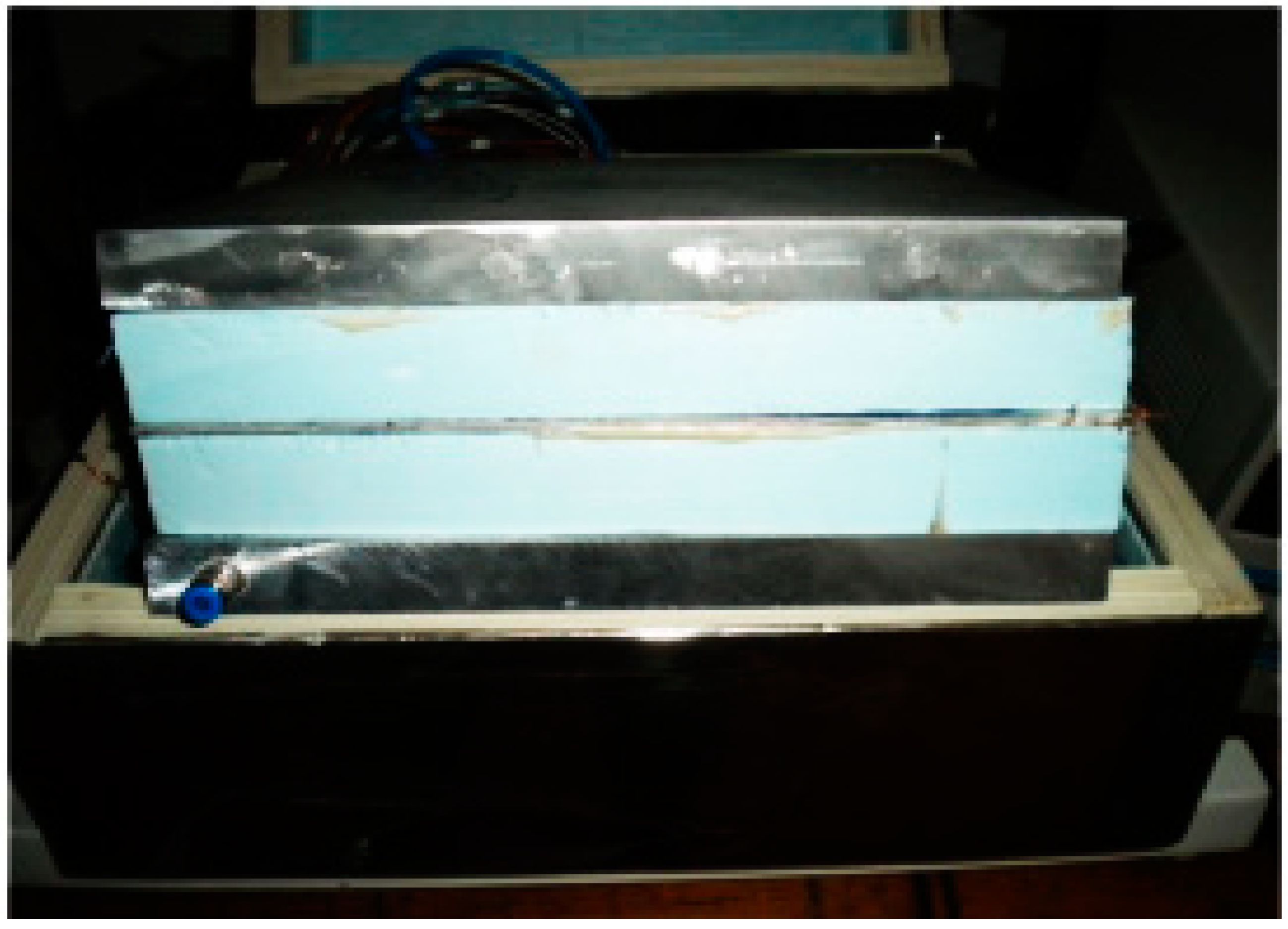
- insertion of the assembly into the measuring enclosure (Figure 10);
- -
- connecting the cold plates to the water;
- -
- starting the power sources and connecting the hot plate to them;
- -
- adjusting the heating/heating current of the centerline resistance;
- -
- connecting to the PC the purchase plate and starting the data acquisition program;
- -
- setting the operating range of the vacuum pump and starting it in the “automatic” mode of the program interface;
- -
- initial temperature stabilization (2 ... 3 h);
- -
- adjusting the voltage/heating current of resistance protection area to obtain a maximum temperature difference of 0.4 °C between it and the central measuring zone;
- -
- secondary temperature stabilization (4 ... 6 h);
- -
- collecting data.
The composite material made and analyzed is made up of PCM-RB01 butyl stearate microcapsules representing the reinforcement phase and Portland cement representing the matrix phase. The mixing ratio achieved was 60% of the total mass represented by the matrix phase and 40% of the total mass represented by the PCM microcapsules. For experiments, some 250 × 250 × 50 mm specimens with an individual mass of 5.31 kg were used, of which 3.18 kg representing the matrix phase and 2.2 kg representing PCM microcapsules. The known encapsulation ratio of 37.5% results in a total mass of PCM material of 825 g per specimen.
The test method and the thermal conductivity test apparatus were determined according to standard ASTM C177, standard for measurement of stationary heat flow measurement by flat and homogeneous specimens whose surfaces are maintained in direct contact with the constant temperature plates. The temperature gradient obtained from the measurements is shown in Figure 11.
3.2. Characterization of Thermal Behavior of PCM-RB01 Microcapsules
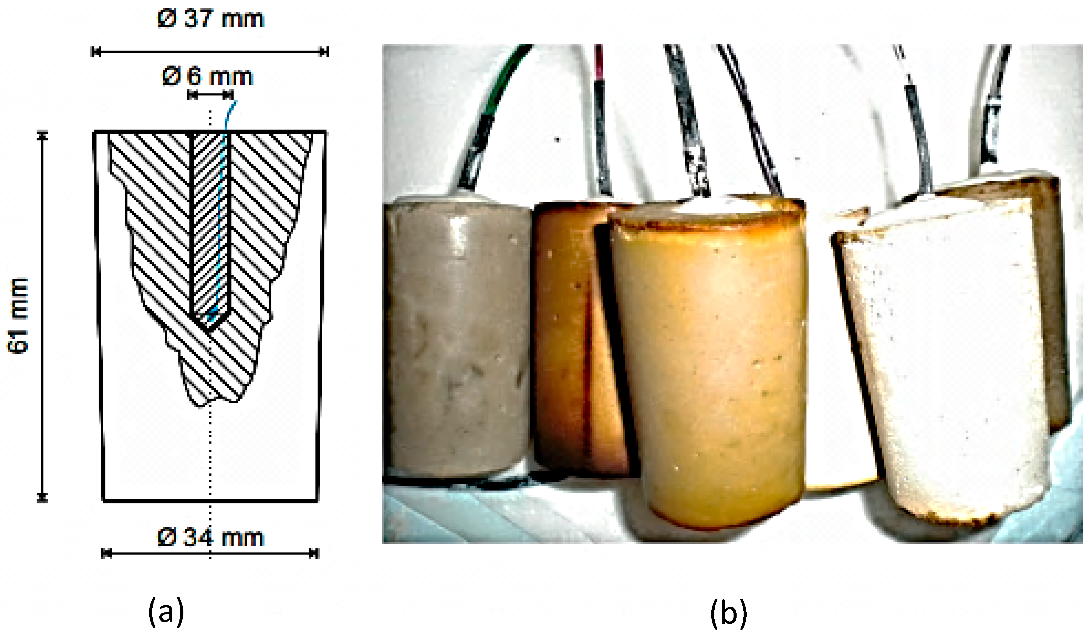
In order to determine the thermal behavior in a cyclic type charge of the developed butyl stearate microcapsules, an experiment was developed to observe this behavior. In the experiment, seven specimens were developed, four of which had integrated butyl stearate and two additional specimens without butyl stearate. The specimens were made by casting the plaster in a permanent form, their geometry being shown in Figure 12. After casting, a temperature sensor was placed in the center of each specimen through Ø 6 mm, reaming, the free space being subsequently filled with plaster. Of the seven specimens, three specimens were made without butyl stearate to determine the thermal behavior characterized only by the sensible heat of the material. Three specimens were made by incorporating butyl stearate under vacuum into the plaster matrix. A sample was made by mixing the developed microcapsules PCM-RB01-butyl stearate in plaster matrices.
The main characteristics of the tested specimens are presented in Table 2.
To determine the thermal behavior of the specimens, a 9106 thermostatic bath produced by PolyScience (Niles, IL, USA) was used. The bath is capable of reproducing temperatures in the range of−20 °C .... +150 °C. For the experiments performed, the temperatures of 20 °C as solidification temperature and 25 °C as the melting temperature of the PCM material were used.
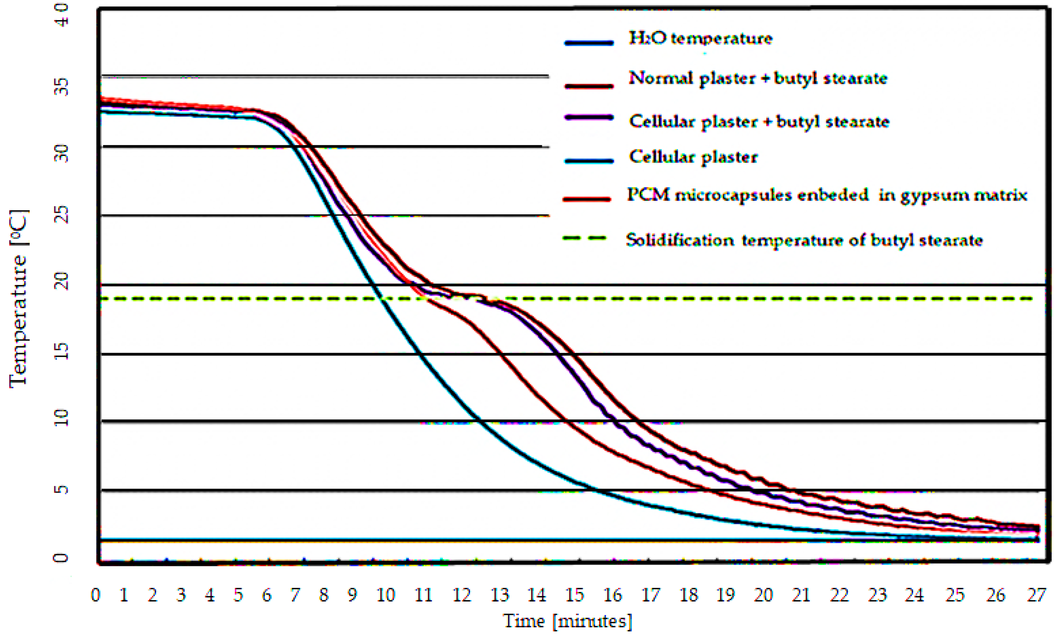
To determine the thermal behavior in a cyclic type loading of the butyl stearate microcapsules, an experiment was developed which tested seven specimens, four of which were incorporated into their butyl stearate composition and three additional samples without butyl stearate. The hypotheses were introduced concomitantly into the thermostatic bath and subjected to 50 melting-solidification cycles to stabilize them. After sample stabilization, individual heat behavior measurements were taken for each sample. Following experiments, the temperature variation graphs of the specimens, shown in Figure 13 and Figure 14, were obtained. The experimental results indicated a characteristic “S” type of the temperature variation graph (Figure 13) for the samples containing butyl stearate. This form is explained by the heat absorption at the phase change of the PCM material. The PCM-containing materials have not exhibited this characteristic shape, the temperature of the specimen being characterized only by the sensible heat of the material.
The temperature variation graph shown in Figure 14 indicates a lower thermal energy absorption capacity for the PCM-RB01 containing sample compared to the vacuum-filled butyl stearate specimen. This is explained by the lower packing factor (20.7% vs. 36%) for the PCM-RB01 microcapsule sample. Despite the lower thermal energy absorption capacity, the developed PCM-RB01 material provides a superior physical stability to the specimen compared to classical integration types.
4. Conclusions
- (1)
- Any building with a high thermal efficiency needs a wall with a high degree of thermal insulation that ensures minimal energy consumption. From this point of view, the storage of thermal energy in the wall is a key factor;
- (2)
- Inside the building, the heat transfer process between walls and applicators is mainly achieved by free air convection upon contact with various surfaces and IR short wave radiation;
- (3)
- Use of PCMs ensures a reduction of thermal fluctuations on the inside by heat storage in the form of phase change;
- (4)
- The main factors in designing such systems are: the temperature limits between which the system must operate; the melting/solidification temperature of the PCM; latent heat of the PCM; degree of thermal loading; configuration of the PCM capsule bed;
- (5)
- Use of PCM micro-capsules can also be done by creating a “Solar Wall” where the incident solar radiation is absorbed by the PCM embedded in the wall, so the stored heat is used for heating and ventilating a house;
- (6)
- The obtained butyl stearate microparticles are in the form of a white powder with a grain size of 0.5–3 mm and the constituent granules exhibit a high friability;
- (7)
- Testing for butyl stearate has a complex viscosity 9 times greater than that of water; the viscous module being greater than the elastic modulus 10 times and all three sizes are approximately constant during the measurement;
- (8)
- Experimental results indicated a characteristic “S” type in the temperature variation plot for the butyl stearate-containing specimens, this form is explained through heat absorption at the phase change of the PCM material;
- (9)
- Although the thermal energy absorption capacity is lower for the developed material, it provides a net superior physical stability to the specimen compared to the classical types of integration;
- (10)
- Experimental research has shown that PCM developed material allows a maximum room temperature reduction of about 4 °C during the day and can reduce the night-time heating load;
- (11)
- Of the temperature variation graphs, a lesser thermal energy absorption capacity was observed for the PCM-RB01 containing sample compared to the vacuum-sucked butyl stearate specimen. This is explained by the lower packing factor (20.7% vs. 36%) for the PCM-RB01 microcapsule sample;
- (12)
- PCM material-free specimens did not exhibit a characteristic S-shape, the temperature of the specimen being characterized only by the sensible heat of the material;
- (13)
- The use of the PCM-RB01 material created in the thermal insulation of the buildings leads to a substantial reduction in energy consumption in both heating and cooling;
- (14)
- Despite the lower thermal energy absorption capacity, the developed PCM-RB01 material provides a superior physical stability to the specimen compared to the classical types of integration.
Author Contributions
The paper is the joint efforts of the authors, their individual contributions being equally given on conceptualization, methodology, analysis, investigation, resources, writing review & editing.
Funding
This research received no external funding.
Conflicts of Interest
The authors declare no conflict of interest.
References
- Kenisarin, M.; Mahkamov, K. Solar energy storage using phase change materials. Renew. Sustain. Energy Rev. 2007, 11, 1913–1965. [Google Scholar] [CrossRef]
- Ahmet, S.; Cemil, A.; Ali, K.; Orhan, U. Microencapsulated n-octacosane as a phase change material for thermal energy storage. Sol. Energy 2009, 83, 1757–1763. [Google Scholar]
- Bland, A.; Khzouz, M.; Statheros, T.; Gkanas, E.I. PCMs for Residential Building Applications: A Short Review Focused on Disadvantages and Proposals for Future Development. Buildings 2017, 7, 78. [Google Scholar] [CrossRef]
- Branko, Š. Smart Crack Control in Concrete through Use of Phase Change Materials (PCMs): A Review. Materials 2018, 11, 654. [Google Scholar] [Green Version]
- Alawadhi, E.M. Thermal analysis of building brick containing phase change material. Energy Build. 2008, 40, 351–357. [Google Scholar] [CrossRef]
- Chung, M.H.; Park, J.C. An Experimental Study on the Thermal Performance of Phase-Change Material and Wood-Plastic Composites for Building Roofs. Energies 2017, 10, 195. [Google Scholar] [CrossRef]
- Bendic, R.; Amza, G. Encapsulation of butyl stearate as a phase change material for thermal energy storage in intelligent building walls. In Proceedings of the 4th International Conference on Structural Analysis of Advanced Materials, ICSAAM, Sinaia, Romania, 7–11 September 2011. [Google Scholar]
- Schossig, P.; Henning, H.-M.; Gschwander, S.; Haussmann, T. Micro-encapsulated phase-change materials integrated into building materials. Sol. Energy Mater. Sol. Cells 2005, 89, 297–306. [Google Scholar] [CrossRef]
- Tyagi, V.V.; Buddhi, D. PCM thermal storage in buildings: A state of art. Renew. Sustain. Energy Rev. 2007, 11, 1146–1166. [Google Scholar] [CrossRef]
- Amza, G.; Milica, A.; Bendic, R. Contributions on the use of ultrasonic remaking process of printing plates. In Proceedings of the Annual Symposium of the Institute of Solid Mechanics SISOM 2010 and Session of the Commission of Acoustics, Bucharest, Romania, 27–28 May 2010. [Google Scholar]
- Zhang, Y.; Zhou, G.; Lin, K.; Zhang, Q.; Di, H. Application of latent thermal energy storage in buildings: State-of-the-art and outlook. Build. Environ. 2007, 42, 2197–2209. [Google Scholar] [CrossRef]
- Chen, F. Leakage Control and Characterization of Form Stable Phase Change Materials: Polymer (Matrix)/Polymer (PCM) Binary Blends and Natural Fiber/Polymer(Matrix)/Polymer (PCM) Ternary Composites; Washington State University: Pullman, WA, USA, 2013; Volume 131. [Google Scholar]
- Chen, F.; Wolcott, M.P. Miscibility studies of paraffin/polyethylene blends as form-stable phase change materials. Eur. Polym. J. 2014, 52, 44–52. [Google Scholar] [CrossRef]
- Khudhair, A.M.; Farid, M.M. A review on energy conservation in building applications with thermal storage by latent heat using phase change materials. Energy Convers. Manag. 2004, 45, 263–275. [Google Scholar] [CrossRef]
- Chen, F.; Wolcott, M.P. Polyethylene/paraffin binary composites for phase change material energy storage in building: A morphology, thermal properties, and paraffin leakage study. Sol. Energy Mater. Sol. Cells 2015, 137, 79–85. [Google Scholar] [CrossRef]
- Rufuss, D.D.W.; Suganthi, L.; Iniyan, S.; Davies, P.A. Effects of nanoparticle-enhanced phase change material (NPCM) on solar still productivity. J. Clean. Prod. 2018, 192, 9–29. [Google Scholar] [CrossRef]
- Beginn, U. Applicability of frozen gels from ultrahigh molecular weight polyethylene and paraffin waxes as shape persistent solid/liquid phase change materials. Macromol. Mater. Eng. 2003, 288, 245–251. [Google Scholar] [CrossRef]
- Zhou, D.; Zhao, C.Y.; Tian, Y. Review on thermal energy storage with phase change materials (PCMs) in building applications. Appl. Energy 2012, 92, 593–605. [Google Scholar] [CrossRef] [Green Version]
- Johan, H.; Chris, B.; Viktoria, M. Combining thermal energy storage with buildings—A review. Renew. Sustain. Energy Rev. 2015, 42, 1305–1325. [Google Scholar]
- Gracia, A.; Cabeza, L. Phase change materials and thermal energy storage for buildings. Energy Build. 2015, 103, 414–419. [Google Scholar] [CrossRef]
- Ye, R.; Fang, X.; Zhang, Z.; Gao, X. Preparation, Mechanical and Thermal Properties of Cement Board with Expanded Perlite Based Composite Phase Change Material for Improving Buildings Thermal Behavior. Materials 2015, 8, 7702–7713. [Google Scholar] [CrossRef] [PubMed] [Green Version]
- Konuklu, Y.; Ostry, M.; Paksoy, O.H.; Charvat, P. Review on using microencapsulated phase change materials (PCM) in building applications. Energy Build. 2015, 106, 134–155. [Google Scholar] [CrossRef]
- Vyas, G.S.; Jha, K.N. Benchmarking green building attributes to achieve cost effectiveness using a data envelopment analysis. Sustain. Cities Soc. 2017, 28, 127–134. [Google Scholar] [CrossRef]
- Rwei, S.P.; Tuan, H.N.; Chiang, W.Y.; Way, T.F. Synthesis and Characterization of pH and Thermo Dual-Responsive Hydrogels with a Semi-IPN Structure Based on N-Isopropylacrylamide and Itaconamic Acid. Materials 2018, 11, 696. [Google Scholar] [CrossRef] [PubMed]
- Aguilar, M.R.; Roman, J.S. Smart Polymers and Their Applications; Elsevier: Amsterdam, The Netherlands, 2014. [Google Scholar]
- Kumar, A.; Srivastava, A.; Galaev, I.Y.; Mattiasson, B. Smart polymers: Physical forms and bioengineering applications. Prog. Polym. Sci. 2007, 32, 1203–1237. [Google Scholar] [CrossRef]
- Guillame-Gentil, O.; Semeno, O.; Roca, A.S.; Groth, T.; Zahn, R.; Voros, J.; Zenobi Wong, M. Engineering the extracellular environment: Strategies for building 2D and 3D cellular structures. Adv. Mater. 2010, 22, 5443–5462. [Google Scholar] [CrossRef] [PubMed]
- Alam, T.E. Experimental Investigation of Encapsulated Phase Change Materials for Thermal Energy Storage. Ph.D. Thesis, University of South Florida, Tampa, FL, USA, 2015. [Google Scholar]
- Guarino, F.; Longo, S.; Ceilura, M.; Mistreta, M.; La Rocca, V. Phase Change Materials Applications to Optimize Cooling Performance of Buildings in the Mediterranean Area: A Parametric Analysis. Energy Procedia 2015, 78, 1708–1713. [Google Scholar] [CrossRef]
- Memon, S.A.; Liao, W.; Yang, S.; Cui, H.; Shah, S.F.A. Development of Composite PCMs by Incorporation of Paraffin into Various Building Materials. Materials 2015, 8, 499–518. [Google Scholar] [CrossRef] [PubMed]
- Farnam, Y.; Krafc, M.; Liston, L.; Washington, T.; Erk, K.; Tao, B.; Weiss, W.J. Evaluating the use of phase change materials in concrete pavement to melt ice and snow. J. Mater. Civ. Eng. 2015, 28, 04015161. [Google Scholar] [CrossRef]
- Yang, H.; Memon, S.A.; Bao, X.; Cui, H.; Li, D. Design and Preparation of Carbon Based Composite Phase Change Material for Energy Piles. Materials 2017, 10, 391. [Google Scholar] [CrossRef] [PubMed]
- Amza, G.; Bendic, R. Utilization of ultrasound emulsion in complex coacervation of polymeric microcapsules. In Proceedings of the Annual Symposium of the Institute of Solid Mechanics SISOM 2011 and Session of the Commission of Acoustics, Bucharest, Romania, 25–26 May 2011. [Google Scholar]
- Aguayo, M.; Das, S.; Castro, C.; Kabay, N.; Sant, G.; Neithalath, N. Porous inclusions as hosts for phase change materials in cementitious composites: Characterization, thermal performance, and analytical models. Constr. Build. Mater. 2017, 134, 574–584. [Google Scholar] [CrossRef]
- Norvell, C.; Sailor, D.J.; Dusicka, P. The effect of microencapsulated phase-change material on the compressive strength of structural concrete. J. Green Build. 2013, 8, 116–124. [Google Scholar] [CrossRef]
Figure 1.
Methods of integration of PCM materials in to intelligent constructions.

Figure 2.
Different macro-encapsulation methods. (a) tubing encapsulation; (b) plate encapsulation; (c) encapsulation in the form of HDPE spheres; (d) encapsulation in the form of metal spheres; (e) encapsulation in PCV panels; (f) encapsulation in aluminum panels; (g) encapsulation in aluminum bags; (h) graphite-PCM compound; (i) encapsulation in granular form.

Figure 3.
Schematic representation of heat transfer phenomena within a building.
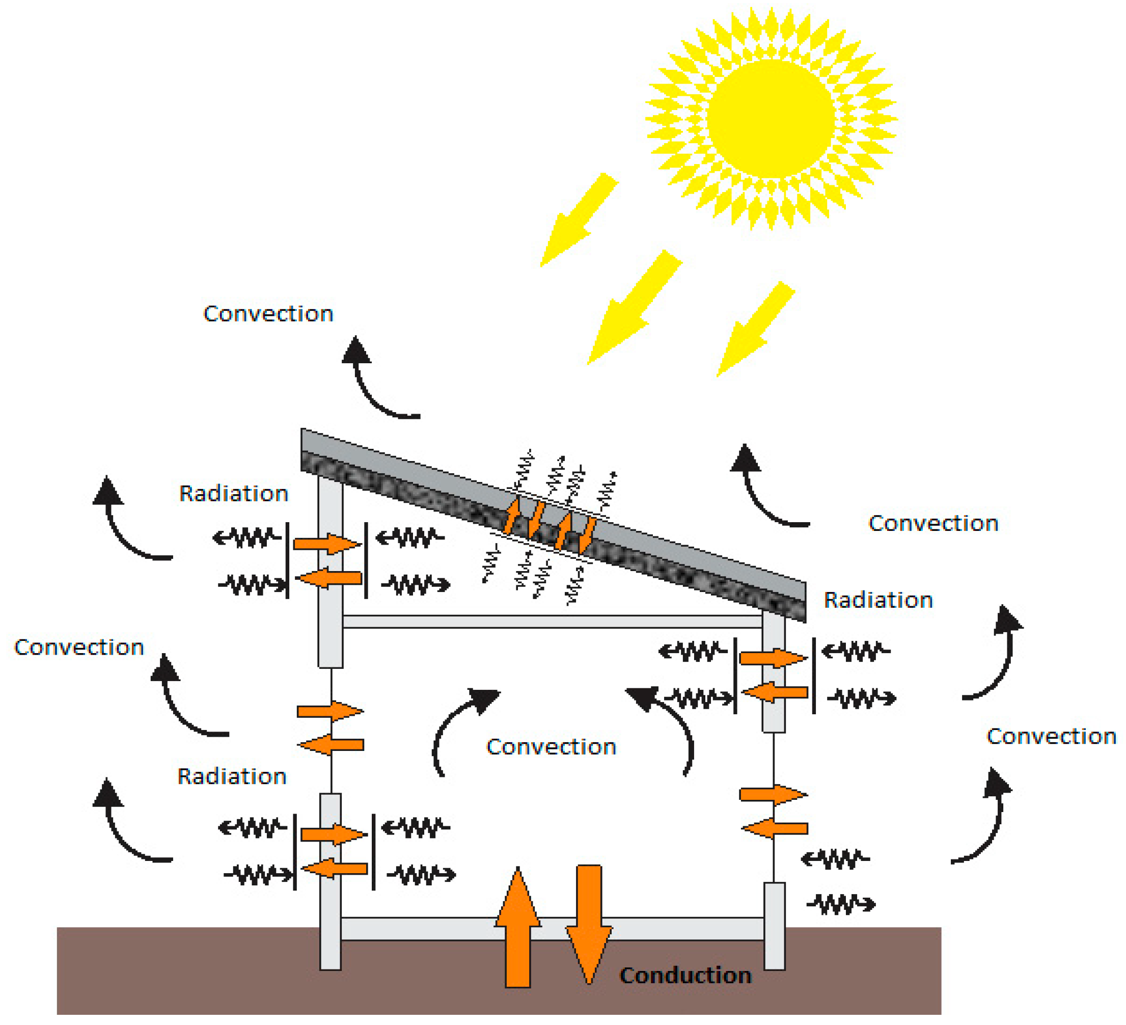
Figure 4.
Thermal energy storage system with PCM macro capsules.

Figure 5.
Elastic modulus, viscous module and complex viscosity for first emulsification, measured at 24 h from emulsion production.
Figure 5.
Elastic modulus, viscous module and complex viscosity for first emulsification, measured at 24 h from emulsion production.
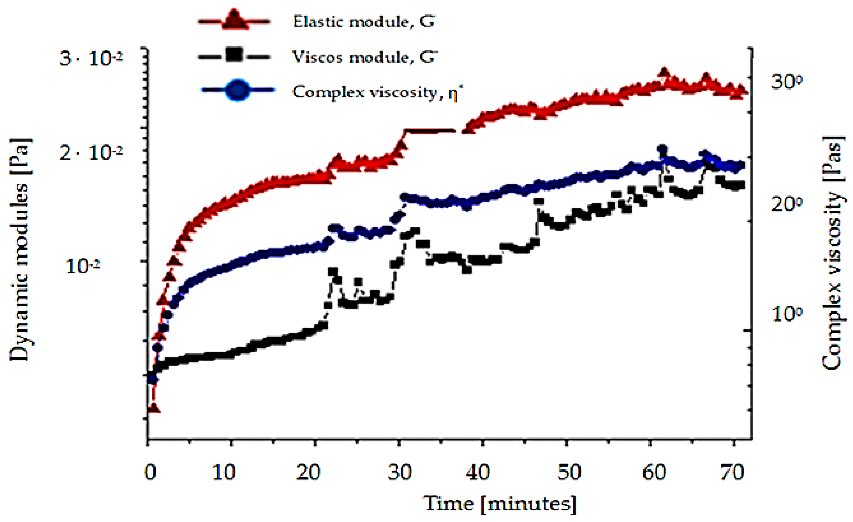
Figure 6.
Polymerization result for butyl stearate microcapsules.

Figure 7.
Images obtained by optical microscopy of PMMA-butyl stearate microcapsules, 100× magnification.
Figure 7.
Images obtained by optical microscopy of PMMA-butyl stearate microcapsules, 100× magnification.

Figure 8.
Section through designed and made composite material, type PCM-RB01.

Figure 9.
Stand used for experimentation: (a,b) measuring chamber and vacuum pump; (c) warm plate, specimen and two cold plates; (d) temperature sensors; (e) vacuum pump and separate electrovalve.
Figure 9.
Stand used for experimentation: (a,b) measuring chamber and vacuum pump; (c) warm plate, specimen and two cold plates; (d) temperature sensors; (e) vacuum pump and separate electrovalve.

Figure 10.
The assembly hot plate-specimen-cold plates.

Figure 11.
Grafic of the temperatures obtained during the experiments.
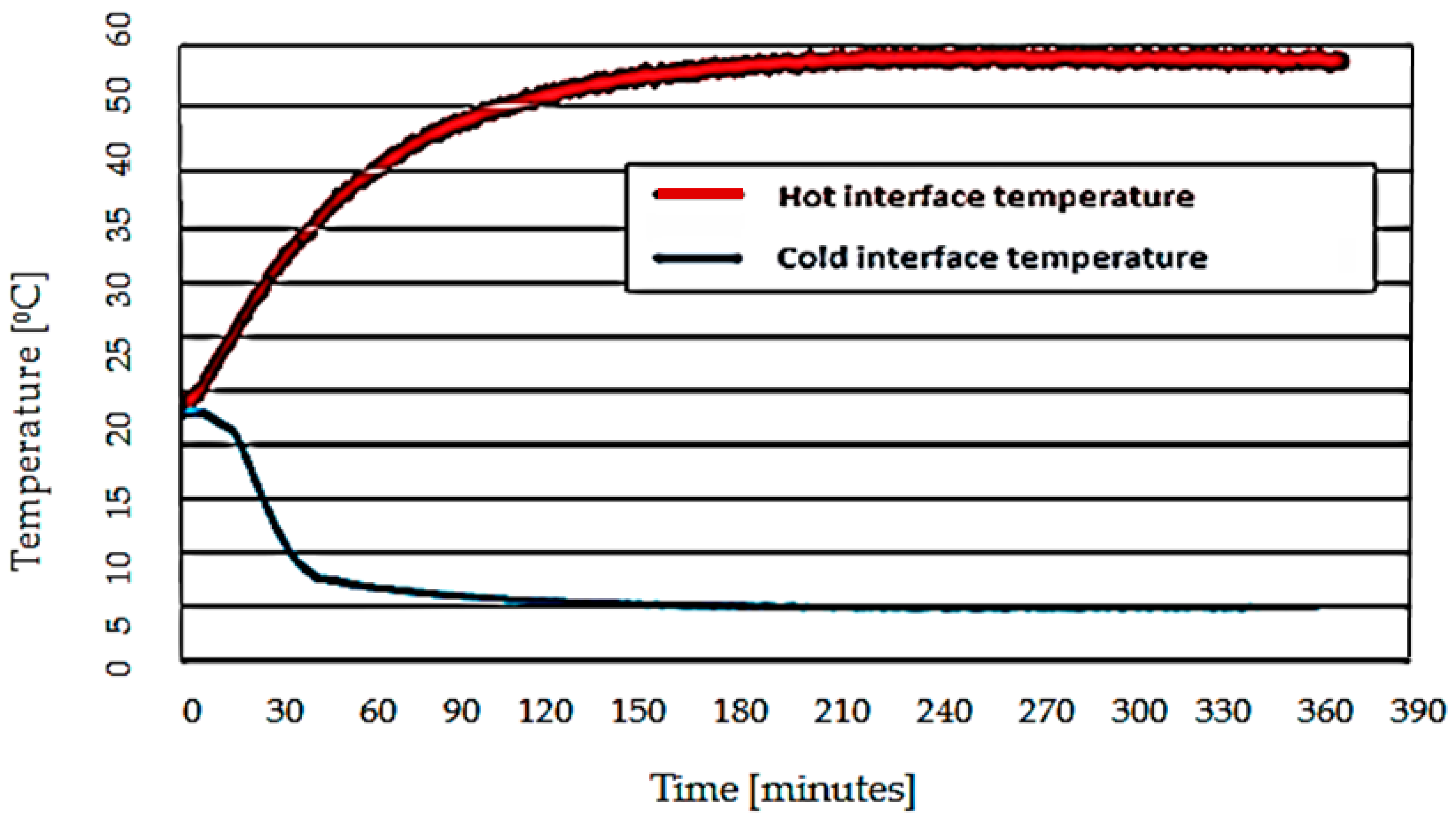
Figure 12.
Test specimens used in the experiment: (a) the specimen geometry; (b) the obtained specimens.
Figure 12.
Test specimens used in the experiment: (a) the specimen geometry; (b) the obtained specimens.

Figure 13.
Measured temperature graph for the seven specimens at the solidification stage. a—characteristic shape “S” corresponding to latent heat of solidification of PCM material; b—the normal characteristic shape, corresponding to sensitive heat.
Figure 13.
Measured temperature graph for the seven specimens at the solidification stage. a—characteristic shape “S” corresponding to latent heat of solidification of PCM material; b—the normal characteristic shape, corresponding to sensitive heat.
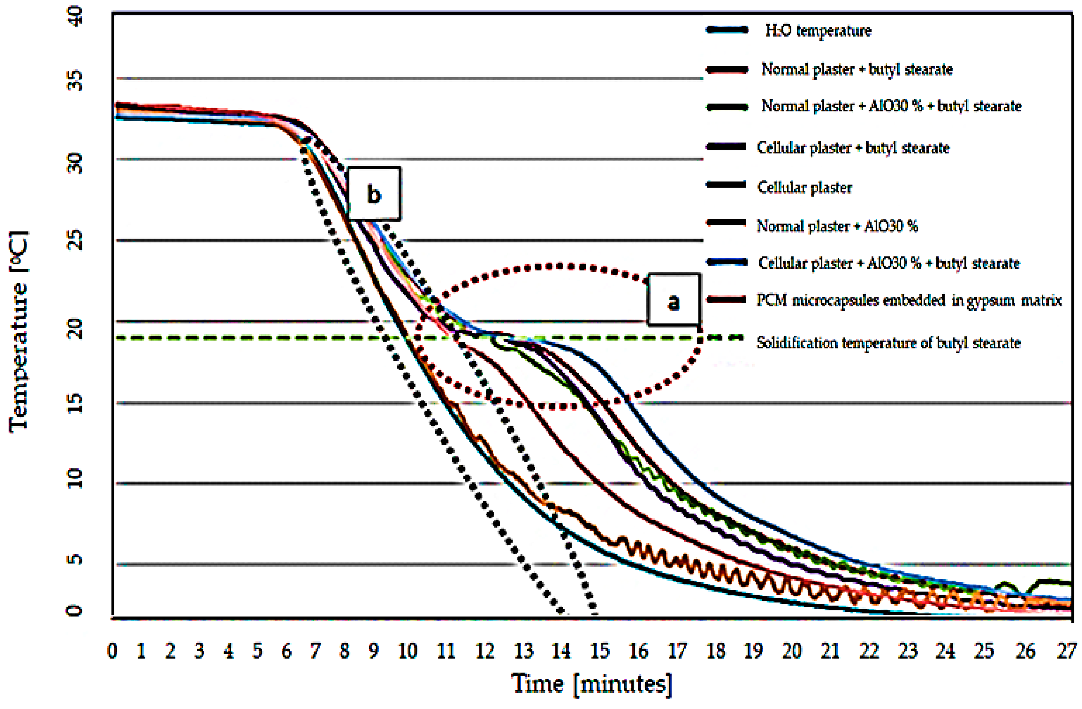
Figure 14.
Measured temperature graph for PCM and test specimens specimen made of cellular plaster at the solidification stage.
Figure 14.
Measured temperature graph for PCM and test specimens specimen made of cellular plaster at the solidification stage.

Table 1.
The details of the micro-encapsulation experiment.
| The Phases of Micro-Encapsulation Process | Time | Components | Quantity |
|---|---|---|---|
| Emulsification I | 30 min | Water | 100 mL |
| Butyl stearate | 25 g | ||
| Pluronic PE6200 | 2 g | ||
| Emulsification II | 30 min | EM1 | - |
| PMMA | 25 g | ||
| alil-MMA | 2.5 g | ||
| Sol. FeSO4-7H2O | 1 mL | ||
| Ammonium persulphate | 0.25 g | ||
| Emulsification III | 1 h | EM2 | - |
| Na2S2O7 | 0.25 g | ||
| AZDN | 1 g | ||
| Precipitation | 6–8 h | - | - |
| Dry precipitation | 24–36 h | - | - |
Table 2.
The main characteristics of the tested samples.
| No. Sample | Sample | Method of Integrating PCM Material | Mass of Sample before Insertion of PCM Material [g] | Mass of Specimen after Insertion of PCM Material [g] | Packaging Report |
|---|---|---|---|---|---|
| 1 | Expanded plaster | n.a. | 68.2 | 68.2 | 0.0% |
| 2 | Expanded plaster + Butyl stearate | Soaking under vacuum | 67.8 | 90.7 | 33.8% |
| 3 | Expanded plaster + AlO 30% | n.a. | 73.2 | 73.2 | 0.0% |
| 4 | Expanded plaster+ AlO 30% + Butyl stearate | n.a. | 79.2 | 97.2 | 22.7% |
| 5 | Plaster + Butyl stearate | Soaking under vacuum | 70.8 | 96.3 | 36.0% |
| 6 | Plaster + AlO 30% + Butyl stearate | Soaking under vacuum | 73.6 | 97.6 | 32.6% |
| 7 | PMMA microcapsules embedded in plaster | Microcapsule blend before casting | 61.1 | 95.42 | 13.3% |
© 2018 by the authors. Licensee MDPI, Basel, Switzerland. This article is an open access article distributed under the terms and conditions of the Creative Commons Attribution (CC BY) license (http://creativecommons.org/licenses/by/4.0/).
Share and Cite
MDPI and ACS Style
Bendic, V.; Dobrotă, D. Theoretical and Experimental Contributions on the Use of Smart Composite Materials in the Construction of Civil Buildings with Low Energy Consumption. Energies 2018, 11, 2310. https://doi.org/10.3390/en11092310
AMA Style
Bendic V, Dobrotă D. Theoretical and Experimental Contributions on the Use of Smart Composite Materials in the Construction of Civil Buildings with Low Energy Consumption. Energies. 2018; 11(9):2310. https://doi.org/10.3390/en11092310
Chicago/Turabian StyleBendic, Vasile, and Dan Dobrotă. 2018. "Theoretical and Experimental Contributions on the Use of Smart Composite Materials in the Construction of Civil Buildings with Low Energy Consumption" Energies 11, no. 9: 2310. https://doi.org/10.3390/en11092310
Note that from the first issue of 2016, this journal uses article numbers instead of page numbers. See further details here.