Design, Analysis of the Location and Materials of Neodymium Magnets on the Torque and Power of In-Wheel External Rotor PMSM for Electric Vehicles


Department of Ship Automation, Gdynia Maritime University, 81-225 Gdynia, Poland
Energies 2018, 11(9), 2293; https://doi.org/10.3390/en11092293
Submission received: 24 July 2018
/
Revised: 26 August 2018
/
Accepted: 28 August 2018
/
Published: 31 August 2018
(This article belongs to the Section F: Electrical Engineering)
Abstract
:The technology of mounting electric direct drive motors into vehicle wheels has become one of the trends in the field of electric vehicle drive systems. The article presents suggestions for answering the question: How should magnets be mounted on the External Rotor Permanent Magnet Synchronous Machine (ERPMSM) with three phase concentrated windings, to ensure optimal operation of the electric machine in all climatic and weather conditions? The ERPMSM design methodology is discussed. Step by step, a method related to the implementation of subsequent stages of design works and tools (calculation methods) used in this type of work are presented. By means of FEM 2D software, various ERPMSM designs were analyzed in terms of power, torque, rotational speed, cogging torque and torque ripple. The results of numerical calculations related to variations in geometric sizes and application of different base materials for each of ERPMSM machine components are presented. The final parameters of the motor designed for mounting inside the wheel of the vehicle are presented (Power = 53 kW, Torque = 347 Nm; Base speed = 1550 RPM), which correspond to the adopted initial assumptions.
1. Introduction
The reduction of energy consumption from fossil fuels is an inspiration for many designers in undertaking the effort of designing new structures used in electric vehicles. One of the trends in the field of electric drive systems is the possibility of using electric machines mounted directly in the wheel of a driven vehicle, according to the invention of Wellington Adams from 1884 (US Patent 300827). Designing an electric motor mounted inside the wheel is a challenge for designers, because the developed design should be characterized by high durability and energy efficiency while having low weight. In this type of electric machines, the rotor is located on the outside of a stationary centrally mounted stator (PMSM (Permanent Magnet Synchronous Machine), ERPMSM (External Rotor PMSM), and ORPMSM (Outer Rotor PMSM)), unlike in classic synchronous motors with permanent magnets (IRPMSM (Internal Rotor PMSM)). One of the aspects to which attention is paid during designing an in-wheel electric machine is the method of attaching the magnets used in the electromagnetic circuit to the rotor.
The purpose of this paper is to analyze the possibilities of changing the geometrical dimensions of an electrical machine, in particular the method of magnets assembly and the materials used for its manufacture. This is a significant issue, giving the answer to the question: At what geometrical dimensions and materials used will we obtain the most power, torque and efficiency from a given volume of the electric machine as well as the smallest cogging torque and torque pulsations? The right choice of materials and geometric dimensions of the machine can contribute to reduction of electric energy consumption of the vehicle. Less energy consumed for vehicle movement directly translates into the parameters obtained by it, i.e., the achieved range and the total efficiency of the entire electric drive system.
The main reason for using electric motors for in-wheel drive is the possibility of reducing the space occupied by the motors onboard the vehicle and complete elimination of the intermediary mechanisms between the drive unit and the vehicle wheels. Thanks to this, an additional space for mounting the battery pack or a luggage compartment appears in the vehicle. The lack of a drive transmission system also promotes greater efficiency of energy recovery during the regenerative braking process. In addition, the user does not have to worry about the maintenance and servicing of the drive train, and the access to the motors in case of necessary service is very quick and simple. The design with motors built into the wheels causes that the motors have a large diameter while maintaining a small thickness. The effect of geometric dimensions of such an electric machine, in which the rotor is located on the outside, is a large torque. In addition, synchronous motors built into the wheel are characterized by high dynamics and the ability to generate very high accelerations. Lack of gears and other wearing out components allow them to operate in a wide range of temperatures while maintaining high efficiency, long life and generating less noise. Another reason for using torque motors is the high efficiency of the entire drive system, compared to systems equipped with a central motor and gears, characterized by efficiency at the level of 0.97–0.99. In addition to the benefits mentioned above, electric motors mounted in the vehicle wheels increase its maneuverability and stability of driving [1,2,3], especially in systems with 4 × 4 or 6 × 6 drive [4,5,6,7,8]. Application of in-wheel motors allows taking advantage of possibilities presented by electric drive, such as fully controlled regenerative braking [9,10].
Unfortunately, the technology associated with the mounting of electric motors in vehicle wheels also has disadvantages. The main engineering problem is to endure the operating conditions in which this type of electric machine must work. Continuous exposure to vibration and shocks, along with cyclic changes in ambient temperatures and humidity are stimulating research, with main focus on the optimization of dimensions and the selection of materials used to manufacture motors, so that they are reliable. The dimensions of the motors and the materials used affect their mass. Increasing the unsprung mass of the propulsion system of the vehicle (electric motor with a wheel and suspension elements not firmly attached to the vehicle body) adversely affects the traction properties. The problem of developing optimal technology of vehicle wheel hub electric motors is the subject of research by many scientific centers and companies, which include: Brabus, Elaphe, ECOmove, Fischer Elektromotoren GmbH, Haiyinciman, Micro Motor, MAGNAX, NTN, Printed Motor, Protean Electric, TM4, and Ziehl-Abegg. These companies are mainly located in Europe, North America, Southeast Asia and Japan.
Contemporary designs of electric motors that are used in the wheels of a vehicle base their principle on the structure of such electrical machine types as: DC motors [11,12,13], asynchronous (induction), reluctance [14,15,16,17,18] and synchronous [19,20]. Due to high efficiency, torque and generated power, the most common are permanent magnet synchronous motors and BLDC motors. The design and analysis of the BLDC motor properties for operation in the wheel hub have been presented in [21], while synchronous motor design process is presented in [22,23,24,25,26,27,28,29]. An important aspect related to motor design is to obtain as much torque and power as possible from its volume [30], while limiting the cogging torque and torque pulsations [31]. For the wheel mounted electric machine to achieve the optimal traction properties, research was performed concerning the following aspects: a hybrid pole–slot combination that can provide decoupling of torque and power characteristics at different speed ranges [32]; application of permanent magnets of various geometric shapes and composition [33,34,35,36]; design procedures [37,38,39,40]; or the methods of controlling the electrical machine [41,42,43,44]. Different ways of mounting magnets on motor rotors (External Rotor PMSM or Outer Rotor PMSM) that can be installed in the wheel can be found in the patent literature [45,46,47,48,49,50].
An important issue in the design of PMSM motors is the way the magnets are arranged on the rotor and their mountings. The materials from which the magnets, stator and rotor are made are also significant. Every fraction of a percent of overall motor efficiency that is possible to gain while designing the components of the electromagnetic circuit later affects the energy savings and increases the range of the electric vehicle.
The main purpose of this article is to analyze the method of mounting the magnets on the ERPMSM rotor embedded in the wheel hub of the vehicle (Figure 1). The correct selection of the shape of the magnets and the way they are assembled, as well as the materials used, will allow optimal use of space in the wheel to obtain maximum power, torque and efficiency, while maintaining a minimum value of torque pulsations and cogging torque value. Against the background of the cited literature, this article presents new unique solutions in the field of the design of magnet assembly methods, affecting the quality of parameters obtained by an electric motor.
2. Motor Design Considerations
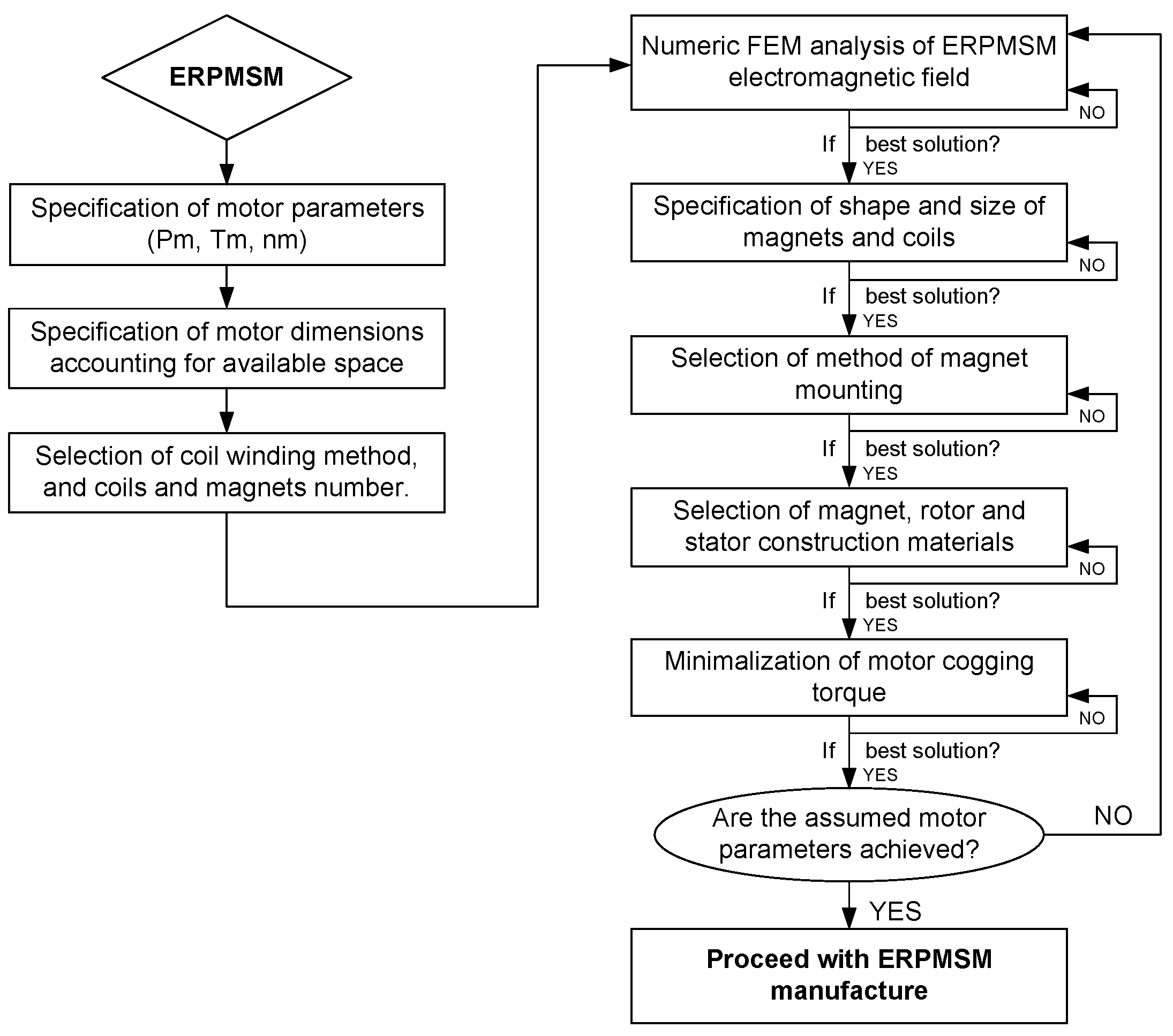
The selection of optimal parameters when designing an electric machine is a multidimensional and multimodal optimization problem, which additionally requires the use of high-performance computers. Moreover, the design process of an electric machine requires calculation of several parameters whose values are mutually dependent, which tends to complicate the optimization calculations [23,37,51,52,53,54,55,56]. The methodology for the design and analysis of ERPMSM parameters has been implemented based on the diagram presented in Figure 2.
The proposed ERPMSM design methodology has been divided into three stages. In the first stage, the target parameters of the motor, specifically the power, torque and rotational speed values. are defined. The geometric dimensions of the motor as well as the number of magnets and coils together with the winding schematic are also defined. Then, in the second stage, for the adopted motor parameters and specific constraints mainly related to the geometric constraints and restrictions caused by the materials used to build the ERPMSM, the input variables of the analytical model are defined. The results of simulation tests for specific combinations of geometrical dimension, adopted specification of power, torque and rotational speed of the electrical machine, as well as the maximum efficiency value and losses occurring, constitute the basis for developing the base motor configuration (refer to Figure 2 [Numeric FEM analysis of ERPMSM electromagnetic field]). With the base motor specification complete, the influence of geometric changes on the adopted assumptions in the first part is analyzed. The results are analyzed considering the costs of implementing a particular solution and feasibility of manufacturing such a configuration, mass of the structure and environmental working conditions. The main problems of this stage concern: determination of the shapes and dimensions of magnets and coils; determining the method of fixing magnets; selection of materials for permanent magnets, rotor and stator; and minimizing the latching torque by twisting the stator or rotor. The last, third stage of the postulated ERPMSM design methodology concerns the selection of a solution recognized as the optimal construction solution, for the adopted assumptions and limitations.
2.1. Identification of Vehicle Parameters
To design an electric motor which will operate in the wheel hub of the vehicle, it is necessary to know the available space inside the wheel rim. Another point of interest is the knowledge of the assumed performance figures of the vehicle in which the motor is to be mounted, the vehicle weight (in this particular case, about 1400 kg), acceleration (about 1.5 m/s2), and top speed (about 130 km/h). With the given parameters available, the demand for power and torque generated by the motor can be determined by considering the forces acting on the vehicle during operation (Figure 3).
The basic forces include the aerodynamic resistance, the rolling resistance, the sliding resistance, the inertia resistance and resistances from the mechanisms of the drivetrain. For the vehicle to be able to move by itself, the sum of occurring resistance forces must be less than the force generated by the propulsion system. Forces acting on the vehicle can be expressed based on classical dependencies:
where FR is the total resistance of the vehicle (), FAD is the total aerodynamic drag force (), FRR is the total rolling resistance (), FS is the total sliding force (), FTD is the force acting on the moving vehicle as a result of friction in the transmission system (), and FIN is the force inertia of the vehicle and trailer system ().
The forces of aerodynamic drag of vehicle were determined from the following dependence:
where Cd is the vehicle drag coefficient , A is the frontal area of the vehicle , ρ is the ambient air density , and V is the vehicle speed
The rolling resistance of a vehicle can be determined based on:
where m is the vehicle mass , g is standard gravity , μRR is the vehicle wheels rolling resistance coefficient , R is the vehicle wheel radius , and α is the road inclination .
The sliding forces acting on the vehicle are based on equation:
The resistance forces of the transmission system resulting from the vehicle’s motion, for a system which would employ a planetary gear in the wheel, were determined based on:
wherein:
where TPG is the torque at planetary gear output shaft at rated speed ωnPG , ωPG is the planetary gear output shaft rotation speed , ωnPG is the nominal rotational speed of the planetary gear output , TDS is the torque at drive shafts at rated speed ωnDS , ωDS is the average speed of wheel drive shafts , ωnDS is the nominal rotational speed of wheel drive shafts, and nPG is the final drive (planetary gear) ratio .
It should be noted that, for a direct drive system, i.e., without a geared transmission, the drag force of the drive train will equal zero, .
Inertia resistance forces arising from the acceleration and braking of the vehicle were determined based on:
where m is the vehicle mass and a is the vehicle acceleration
The source of the traction force is traction torque () generated by an electric motor placed in the wheel hub.
The traction power available on the wheels of the vehicle is equal to the product of the vehicle linear velocity V and traction force FM
The power of the electric drive motor is equal to the total drive power on the wheels divided by the number of wheels equipped with motors. In most designs, there are two or four drive motors.
For a synchronous motor, the power is equal to the product of the motor torque and its rotational speed ():
Taking into account the assumed values—vehicle weight approximately 1400 kg; acceleration approximately 1.5 ; and top speed approximately 130 km/h—and assuming a drive system consisting of four motors with one in each wheel, the demand for motor power would be about 50 kW, the required torque would be 350 Nm and rotational speed would be about 1500 RPM.
2.2. Analysis and Selection of Windings for ERPMSM
With the predicted motor parameters (torque, power and rotational speed), one can proceed with the design of the electromagnetic circuit, determining the number of phases, the number of coils (teeth) and magnets [19,57,58]. The value defining the relationship between the number of concentrated coils and the number of magnets is called the winding factor of the motor, and it can take the maximum value of 1. Motors with the best properties related to the torque they develop have this value close to unity. To make the winding factor optimal, fundamental and secondary assumptions, about the amount and scheme of winding the coils as well as the number of magnets, should be met. The fundamental assumptions are: the number of magnets divisible by 2; the number of concentrated coils divisible by 3; the number of magnets different from the number of concentrated coils; the fulfillment of equality determining the relationship between the multiplicity of the number of phases and the quotient between the number of concentrated coils; and the largest common divisor of the number of concentrated coil and the double of pole pairs number.
The additional assumption is the rejection of winding schemes in which there is an asymmetry of forces acting between the stator and the rotor. This can be achieved by checking whether the largest common divisor of the number of coils and magnets is greater than 2. The method for determining the value of the winding factor kW is shown in [58].
Figure 4 shows the value of the motor winding coefficient kW depending on the various combinations of number of coils and magnets. Non-shaded fields denote the configuration for highly efficient motors. Fields shaded in red represent the configuration for motors that do not meet the basic design requirements. The value of the winding coefficient is shown in the upper part of the cell corresponding to column with specified number of coils and row with specified number of magnets. In the lower part of the cell, the leftmost section displays the number of coil layers possible to be wound with specific magnet and coil combination. The middle section displays cogging steps per rotation for given combination while the rightmost section shows the number of fundamental winding pattern repetitions.
It is assumed that motors with coils with a winding coefficient kW less than 0.5 are ineffective, because they inefficiently use the capabilities of the electric machine in terms of the torque developed by it. It results from the following dependence found in [59].
where T is the Motor torque , kw is the winding factor, Ns is the Number of motor slots, Nt is the number of turns, Nl is the number of winding layers (1 or 2), Bσmax is the peak value of air gap magnetic flux density in , Sσ is the area of air gap, Ip is the phase current peak value, and θ is the advance angle.
Motors with kW in the range from 0.5 to 0.86 have medium efficiency, and electric machines with kW greater than 0.86 are highly efficient. When making the final decision about choosing a given configuration, the number of coils and magnets should be considered, as well as whether the chosen arrangement will be physically possible to manufacture, for example, whether the windings fit in a given space. When designing a motor, parameters such as speed at which it will rotate and what power it will be able to produce should be taken into account. The speed of rotation is dependent on the number of layers and turns on the winding at a given supply voltage, while some of the parameters responsible for the amount of generated power are the number and diameter of copper wires used to wind the motor, and the current density of the stator windings. Bearing in mind the above assumptions, the numerical calculations were based on a motor consisting of 12 coils and 14 magnets, which has the winding coefficient kW of 0.933.
2.3. Selection of ERPMSM Geometric Dimensions
Available space for motor is mainly constrained to the volume inside the wheel rim. Typical wheel sizes used in the vehicles of A and B segments (defined by the European Commission) have rim sizes of 13–14 inches. Considering the way of joining the motor to the suspension, requirements of suspension geometry, including scrub radius and camber (necessitating placement of supports at exact locations) as well as the available space inside the rim (cylindrical space with diameter of 300 mm and width of 140 mm), the dimensions of the electromagnetic circuit of the motor of 280 mm in diameter and 80 mm in thickness were proposed (Figure 5).
2.4. Selection of the Shape and Geometric Dimensions of Magnets
Having accepted the value of the number of coils and magnets, it is proposed that the next step in the design of the ERPMSM electric machine is to determine the shapes and geometric dimensions of the magnets used for the rotor. Four types of magnet shapes (Figure 6) were adopted for the analysis.
The choice of the shape and geometric dimensions of the magnets affects not only the properties of the electromagnetic circuit, but also the cost of motor manufacture.
Figure 7 presents the principle of determination of the length of the magnet measured in electrical degrees in relation to the rotor pole pitch of the electrical machine. The size of the magnet expressed in mechanical degrees is defined by:
where is the angular measure of the magnet expressed in mechanical degrees, is the angular measure of the magnet expressed in electrical degrees, and is the number of magnets (rotor poles).
Magnets used in electromagnetic circuits of electrical machines are one of the most expensive motor components. At the same time, they allow exciting the electromagnetic circuit while maintaining low mass and volume of the motor in relation to other electrical machines. The least expensive ones are rectangular prismatic magnets, arc shaped magnets are more expensive and the most expensive are lenticular ones. Thanks to the appropriate arrangement of magnets on the rotor, e.g. arranged into the Halbach array, it is possible to obtain the effect of strengthening the magnetic flux on the rotor’s side facing the air gap and weakening the flux on the rotor iron side.
2.5. Analysis and Selection of Magnet Fixings on the Rotor
The method of mounting magnets on the ERPMSM rotor is a very important aspect related to the correct operation of this electric machine.
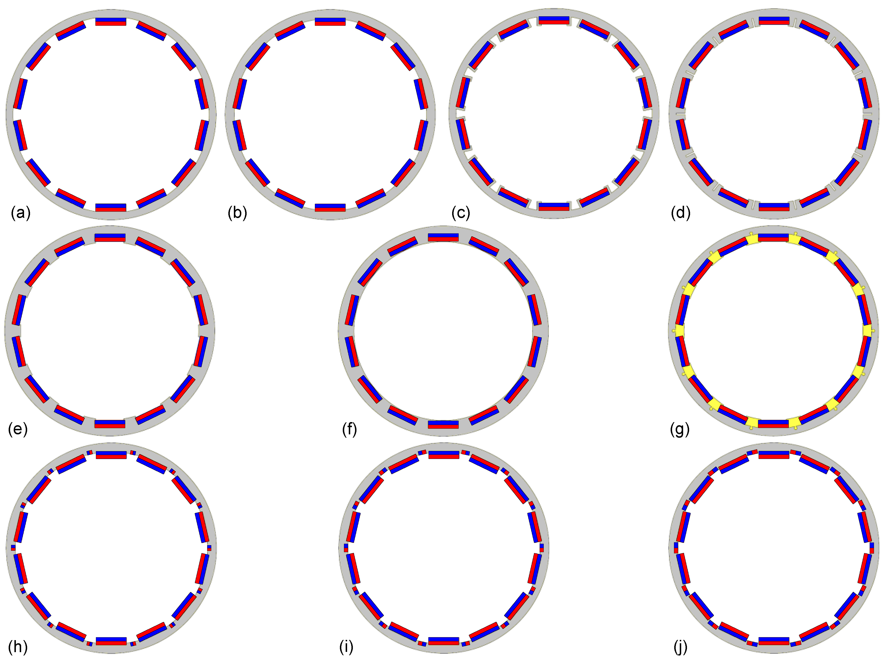
The purpose of ERPMSM is to directly drive the wheel of a vehicle that travels on different surfaces such as asphalt, pavement, gravel, stones, sand, mud, snow, ice, etc., with different rotational speeds, in the presence of different temperature conditions (hot, cold, and frost) and varying degrees of humidity (including periodic partial, or total immersion in water or mud). Road surface irregularities cause the wheel mounted motor to experience shocks and vibration. In addition, the magnets mounted on the rotor are subjected to forces caused by action of the coils in the electromagnetic circuit. Very high values of current in the stator circuit, along with extra harmonic content introduced from the inverter circuit can cause heating of magnets, and in extreme cases demagnetization, following their detachment from the rotor surface and permanent damage [60]. The method of mounting magnets on the ERPMSM rotor is to ensure optimal use of their magnetic properties, without compromising the developed parameters of the motor, and regardless of the environmental conditions in which they are used. In this work, various methods of mounting neodymium magnets on the rotor were analyzed (Figure 8): flat on the rotor surface, in milled recesses, through hooks with varying spans of air gaps, in pockets buried beneath the surface of the rotor, and flat on the rotor surface mounted using paramagnetic fixtures. Additional effect of introducing extra magnets, arranged into Halbach array, was also taken into consideration.
3. Motor Modeling
Many programs on the market allow modeling various designs of electrical machines, including those that allow comprehensively modeling and testing the parameters of an ERPMSM. The most known software packages are: ANSYS Maxwell, RMXPRT (ANSOFT), SolidWorks (Magnetostatic Analysis), Motor (CAD), JMAG (Designer), MotorSolve, Flux Motor, and MotorAnalysis [61], the last of which was used for experimental validation of ERPMSM. The solution of permanent magnet electric machine electromagnetic circuit was implemented using a two-dimensional approximation, which is based on the assumption that the magnetic field does not depend on the Z coordinate (Z-axis—parallel to the axis of the rotor shaft). Thanks to this, the electromagnetic circuit was considered in the plane of the machine’s cross-section (x–y plane). Thanks to this, in a simplified two-dimensional approach, the current density and the vector of the magnetic field will have only Z components. Thus, they can be expressed in the following way:
where μr is the relative permeability of material, A is the magnetic vector potential, J is the electric current density, σe is the electrical conductivity (S/m), U is the voltage in the region of calculation, and l is the length in the Z-axis.
To solve the simplified two-dimensional circuit defined by Equations (14) and (15), two methods were used. The magnetostatic method using finite elements method (FEM) was used for magnetostatic analysis. However, for Dynamic Finite Element Analysis, a transient finite element method is used. An iterative time procedure was used for both adopted methods, aimed at finding parameters of the electromagnetic circuit, whose parameters change over time.
Basing on the Maxwell stress tensor method, electromagnetic torque can be calculated as follows:
where lm is the motor lamination stack length, Dr is the rotor diameter, dσ is the length of air gap, μ0 is the magnetic permeability of vacuum, Bn is the magnetic flux density in normal direction, and Bt is the magnetic flux density in tangential direction.
The value of electromagnetic force can be determined based on the known value of the magnetic flux coming from magnets placed on the rotor that move between the starting point and the target point:
where is the change in the magnetic field between the starting point and the target point, and is the value of the linear shift.
The torque value is determined in a similar way:
where ∂φ is the value of the angular offset.
In practice, the torque and power generated by a three-phase electric machine depend mainly on its geometrical dimensions, the materials used and design features [14,30,57,62,63,64,65,66,67,68,69] These parameters are determined by the internal apparent power Pi of the machine and the associated internal electromagnetic torque of the machine:
where is the effective voltage value, is the effective current value, K is the geometric coefficient of the motor, and mechanical angular velocity.
where is the voltage pulsation , is the frequency, and p is the number of pole pairs.
where is the shape factor of the excitation field, is the shape factor of induced voltage, is the winding factor, is the linear current density, and is the maximum value of magnetic induction.
where is the shape factor of the excitation field, is the average value of the magnetic induction, and is the maximum value of the magnetic induction.
where is the shape factor of induced voltage, is the effective value of induced voltage, and average value of induced voltage.
The electromagnetic internal torque of the machine can be determined based on:
4. Results of Simulation Research
The space available for an electromagnetic motor circuit is 280 mm in diameter and 80 mm in thickness, and the assumed motor parameters were: base motor speed at 1500 RPM, peak power at 50 kW and torque about 300 Nm.
Table 1 presents the preliminary results of calculations for the electromagnetic circuit with flat magnets, lenticular magnets, arc shaped magnets and the Halbach array magnets. The following values were assumed: the number of coils was 16, the wire cross sectional area (CSA) was 13.4 mm2, the effective current supplying one phase was 150 A, the inverter DC supply voltage was 400 V, and the angular measure of the magnets was 120 °E. The first column of the table shows the method of fixing magnets on the rotor, as explained in Figure 6, and the percent fill of the available angular measure (180° = 100%) of the rotor pole pitch with the permanent magnetic material. The consecutive columns in the following tables contain the values of: maximum possible RMS supply voltage per phase U ; RMS phase voltage URMS ; base rotational speed n0 ; torque T ; cogging torque TP ; maximum efficiency ηmax ; mechanical power PM ; stator copper losses PCu ; and motor iron losses PFe .
Because the assumed rotational speed of the electrical machine at 1500 (RPM) is lower than the values obtained in the tests (Table 1), the number of turns has been increased to 17 with a simultaneous reduction of the wire cross section to 12.8 [mm2]. Table 2 presents the results of simulation tests for the corrected winding.
The obtained base speed value n0 is now consistent with the assumed value. Further tests of the electromagnetic circuit of the electric machine were carried out based on the methodology presented in Figure 2. The results of simulation tests are included in the following tables.
Table 3 shows the influence of changes in the length of arc shaped magnets (Figure 6a) on the value of parameters obtained by ERPMSM.
Table 4 shows the effect of changes in the radius of curvature of the air gap facing surface of the lenticular magnets (Figure 6b) on the value of parameters obtained by ERPMSM. With the increase of the radius curvature of the magnet surface, the thickness of the magnet increases up to the value when the magnet takes the form of flat (prismatic shaped) magnet.
Table 5 and Table 6 present the influence of length and thickness of prismatic magnets (Figure 6c) on the value of parameters obtained by ERPMSM.
Based on the obtained results, it was found that the optimal solution (cost of magnets relative to obtained performance figures of ERPMSM) for the construction of ERPMSM requires the selection of prismatic (flat) magnets. For this reason, this type of magnets was chosen for further analysis.
Table 7 presents the effect of fixing flat magnets on the performance obtained by ERPMSM. The description in the first details how the magnets are attached to the rotor, as shown in Figure 7.
Table 8 shows the impact of the use of various ferromagnetic material grades for construction of the stator on the parameters obtained by ERPMSM. Similarly, Table 9 demonstrates the effect of using various ferromagnetic materials for the construction of the rotor on the performance obtained by ERPMSM. Table 10 presents the outcome of changing the grade of permanent magnet material on the calculated ERPMSM parameters.
Table 10 shows the effect of using magnets made of various magnetic materials on the value of parameters obtained by ERPMSM.
Table 11 shows the effect of skewing the rotor magnets along the shaft axis by the amount of mechanical degrees on the value of parameters obtained by ERPMSM. Similarly, Table 12 shows the effect of twisting the stator coils in the same manner on the obtained ERPMSM parameters.
Figure 10 presents the parameters obtained by ERPMSM using a different way of mounting magnets on the rotor. Methods of assembling magnets on the rotor were analyzed in accordance with the proposals presented in Figure 8: (a) flat on the rotor surface; (b) in milled recesses; (c) by hooks with large spacing; (d) by hooks with small spacing; (e) by hooks with no spacing; (f) in cavities buried beneath the rotor surface; and (g) flat on the rotor surface using paramagnetic holders.
5. Discussion
This section discusses the influence of various methods of attaching neodymium magnets on the rotor to the quality of the obtained ERPMSM parameters. The research was aimed at selecting the method of mounting magnets on the surface of the rotor, which would guarantee stable maintenance of magnets in various operating conditions, while ensuring the assumed torque and power.
Four variants of magnets used in ERPMSM electric machine were proposed for initial testing (Figure 6): arc shaped, lenticular, rectangular prismatic (flat) and flat arranged in the Halbach array. Considering the road conditions influence on the motor installed in the wheel of the vehicle, in which the motor is to be operated, it would seem optimal to use rectangular prismatic shaped magnets. The choice of flat magnets for further analysis was mainly influenced by the reduced cost of manufacture of flat magnets in relation to other magnet types, and the method of their assembly, ensuring resistance to temperature changes as well as vibrations and shocks during operation.
Looking back at the assumed ERPMSM target parameters related to the vehicle power demand, which requires the motor power of about 50 (kW), 340 (Nm) of torque and a rotational speed of 1500 (RPM), and taking into account the manufacture costs of magnets with specific shape, and the method of their attachment to the rotor, rectangular prismatic magnets mounted on the rotor by means of paramagnetic holders (Figure 7g) were chosen as the optimal solution for the adopted dimensions and assumptions. In addition to the magnets’ shape, it is proposed to select the N38UH permanent magnet material, the M235–35A non grain oriented electrical steel material for the stator, and the ARMCO pure iron material for the rotor. The length of rectangular prismatic magnets was assumed at 66.7% of the total available space for the magnet, which equals 120 electrical degrees. For reduction of the cogging torque, the optimal results were obtained for skewing the magnets on the rotor by 3.75°. Table 13 presents the optimal results of the tests obtained during computer simulations for the construction assumptions and materials presented above.
Table 1, Table 2, Table 3, Table 4, Table 5, Table 6, Table 7, Table 8, Table 9, Table 10, Table 11, Table 12 and Table 13 present the largest loss values associated with the operation of an electric machine, i.e. theoretical losses in copper loss and core loss. The theoretical values of the maximum efficiency of ERPMSM given in Table 1,Table 2, Table 3, Table 4, Table 5, Table 6, Table 7, Table 8, Table 9, Table 10, Table 11, Table 12 and Table 13 will in fact be reduced by many other types of losses, of which the most common are bearing losses, winding losses, hysteresis losses, cross-slot losses, stray losses, dielectric losses and other losses. Even if we were able to precisely model all kinds of listed losses, the maximum efficiency parameter is used as a reference parameter, based on which we evaluate properties in the same way for all modeled structures.
Thanks to the adopted methodology of motor design, a high mass power to weight ratio was obtained in ERPMSM at the level of 2.29 kW/kg, with a total active weight of the electric machine components at 25.03 kg, of which individual masses are: rotor at 5.98 kg; stator at 9.29 kg; windings at 6.32 kg; and magnets at 3.44 kg.
Figure 11 presents the waveforms of the obtained parameters by numerical simulations of such quantities as: motor power, torque, efficiency, RMS phase voltage, torque ripple and cogging torque.
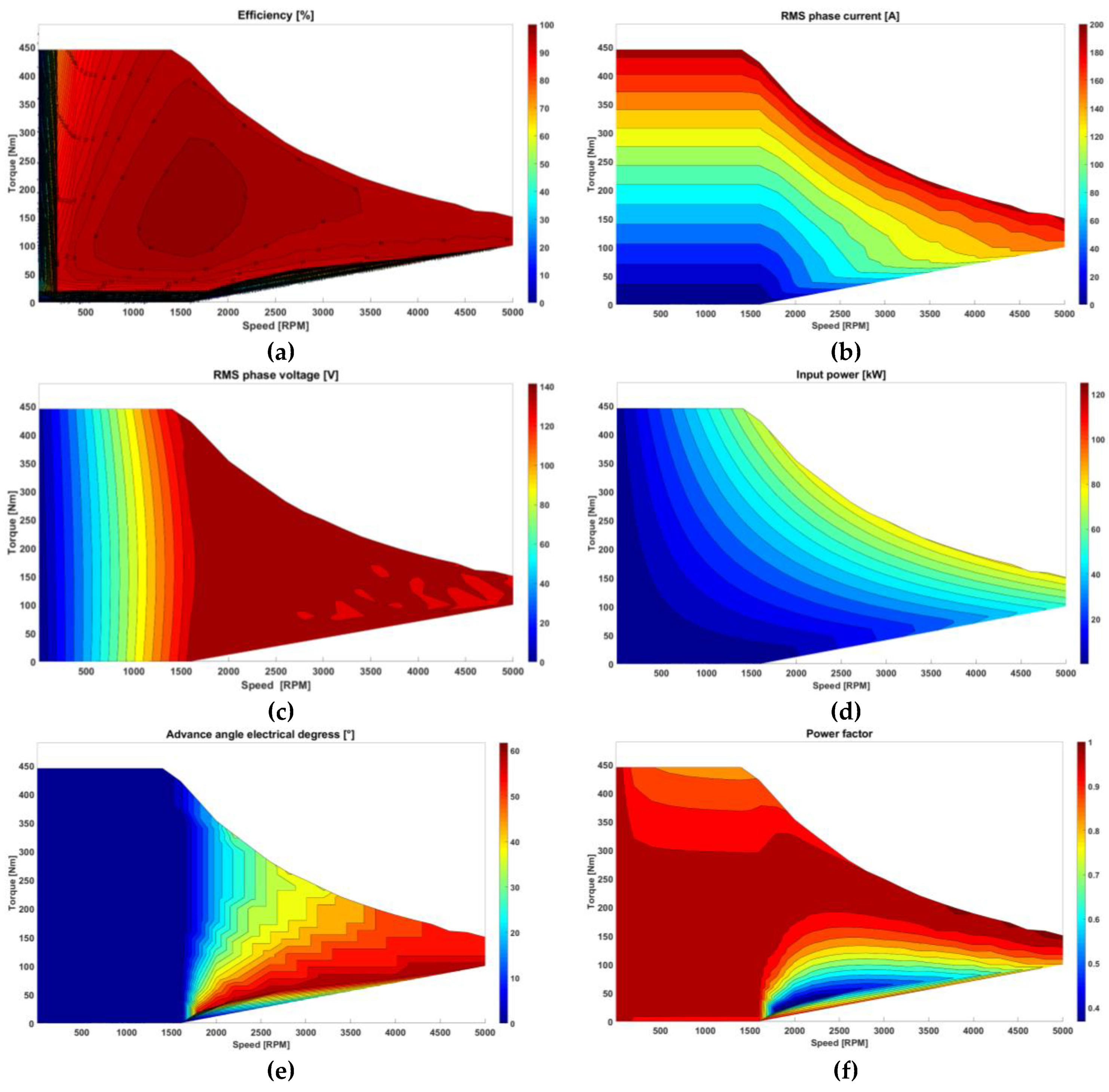
Figure 12 shows the performance maps of the designed External Rotor Permanent Magnet Synchronous Machine (ERPMSM).
Based on the conducted research, it is not possible to clearly indicate a specific dependence (e.g., the ratio of arc fill of the rotor with magnets), the observance of which would guarantee obtaining optimal parameters regardless of the dimensions of a given electric machine.
Designing an electric machine requires special care and considering all motor parameters, especially when the dimensions change. The conducted research confirmed the convergence of the obtained results with other works on similar topics presented in the Introduction [11,12,35,36,38,39,40,43,44]. In the scope of changes in geometric dimensions, shapes and construction of magnets and coils, and the application of materials with different magnetic properties, very similar results were obtained. In the presented works, the subject of verification, in terms of the electromechanical parameters obtained, were geometrical dimensions, machine mass, and materials from which magnets were made. The construction solutions regarding the method of fixing magnets of the same type and shape have not been investigated in any way.
No information was found in the literature related to the effect of magnet assembly and fixing methods on the performance obtained by the electric motor. Against the background of the presented publications, this article presents new unique solutions that affect the quality of parameters obtained by the designed electric machine.
To properly design an electrical machine with the desired parameters, several criteria should be considered to obtain synergistic effect.
6. Conclusions
In this paper, various methods of mounting neodymium magnets for External Rotor Permanent Magnet Synchronous Machine have been presented and analyzed.
The motor design methodology for in-wheel direct drive motors using the FEM 2D method was presented, thanks to which the shape of neodymium magnets and their assembly method were correctly selected.
Thanks to the demonstrated methodology, considering the method of mounting magnets on the rotor, environmental working conditions, materials for magnets, rotor and stator were also selected, which allowed for the optimize the use of space inside the wheel to obtain maximum power, torque and efficiency, while maintaining the minimum value of cogging torque and torque ripple.
The proposed design methodology External Rotor Permanent Magnet Synchronous Machine\provides for reduced mass, reduced leakage flux, and high flux densities to improve performance of the parameters achieved.
ERPMSM machine design is a multicriteria and multistage task, aimed at determining the optimal dimensions and materials used for motor construction, including their production costs and manufacturing possibilities.
Thanks to the presented design methodology, External Rotor Permanent Magnet Synchronous Machine obtained a synergistic effect of cooperation of all electrical machine elements expressed by a high coefficient of developed maximum power from a mass unit of 2.29 [kW/kg].
Funding
This research received no external funding.
Acknowledgments
This research received no external support.
Conflicts of Interest
The author declare no conflict of interest.
References
- Ren, B.; Chen, H.; Zhao, H.; Yuan, L. MPC-based yaw stability control in in-wheel-motored EV via active front steering and motor torque distribution. Mechatronics 2016, 38, 103–114. [Google Scholar] [CrossRef]
- Cao, Y.; Zhai, L.; Sun, T.; Gu, H. Straight Running Stability Control Based on Optimal Torque Distribution for a Four in-wheel Motor Drive Electric Vehicle. Energy Procedia 2017, 105, 2825–2830. [Google Scholar] [CrossRef]
- Liu, M.; Huang, J.; Chao, M. Multi-states Combination Nonlinear Control of In-wheel-motor-drive Vehicle Dynamics Stability. Energy Procedia 2017, 105, 2746–2752. [Google Scholar] [CrossRef]
- Zhang, H.; Zhao, W. Decoupling control of steering and driving system for in-wheel-motor-drive electric vehicle. Mech. Syst. Signal Process. 2018, 101, 389–404. [Google Scholar] [CrossRef]
- Mihály, A.; Gáspár, P.; Németh, B. Multiple fault-tolerant in-wheel vehicle control based on high-level control reconfiguration. IFAC-PapersOnLine 2017, 50, 8606–8611. [Google Scholar] [CrossRef]
- Zeng, X.; Li, G.; Yin, G.; Song, D.; Li, S.; Yang, N. Model predictive control-based dynamic coordinate strategy for hydraulic hub-motor auxiliary system of a heavy commercial vehicle. Mech. Syst. Signal Process. 2018, 101, 97–120. [Google Scholar] [CrossRef]
- Wang, Z.; Wang, Y.; Gao, Z.; Guo, J. Torque Distribution Control Strategy based on Dynamic Axle Load for 8 In-Wheel Motor Drive Vehicle. Energy Procedia 2016, 104, 550–555. [Google Scholar]
- Bauer, P.; Kazmierkowski, M.P.; Strzelecki, R. Multilevel Converters. Bull. Pol. Acad. Sci. Tech. Sci. 2017, 65, 563–565. [Google Scholar] [CrossRef] [Green Version]
- Wang, B.; Huang, X.; Wang, J.; Guo, X.; Zhu, X. A robust wheel slip control design for in-wheel-motor-driven electric vehicles with hydraulic and regenerative braking systems. In Proceedings of the American Control Conference (ACC), Portland, OR, USA, 4–6 June 2014; pp. 3225–3230. [Google Scholar]
- Le Solliec, G.; Chasse, A.; Geamanu, M. Regenerative braking optimization and wheel slip control for a vehicle with in-wheel motors. IFAC Proc. Vol. 2013, 30, 542–547. [Google Scholar] [CrossRef]
- Rahim, N.; Ping, H.; Tadjuddin, M. Design of an in-wheel axial flux brushless dc motor for electric vehicle. In Proceedings of the 2006 International Forum on Strategic Technology, Ulsan, Korea, 18–20 October 2006; pp. 16–19. [Google Scholar]
- Shin, P.S.; Kim, H.D.; Chung, G.B.; Yoon, H.S.; Park, G.S.; Koh, C.S. Shape Optimization of a Large-Scale BLDC Motor Using an Adaptive RSM Utilizing Design Sensitivity Analysis. IEEE Trans. Magn. 2007, 43, 1653–1656. [Google Scholar] [CrossRef]
- Seo, I.M.; Kim, H.K.; Hur, J. Design and analysis of modified spoke type BLDC motor using a ferrite permanent-magnet. In Proceedings of the 17th International Conference on Electrical Machines and Systems (ICEMS), Hangzhou, China, 22–25 October 2014; pp. 1701–1705. [Google Scholar]
- Zhu, J.; Cheng, K.E.; Xue, X.; Zou, Y. Design of a novel high-torque-density in-wheel switched reluctance motor for electric vehicles. In Proceedings of the 2017 IEEE International Magnetics Conference (INTERMAG), Dublin, Ireland, 24–28 April 2017; pp. 1–2. [Google Scholar]
- Oksuztepe, E. In-Wheel Switched Reluctance Motor Design for Electric Vehicles by Using a Pareto-Based Multiobjective Differential Evolution Algorithm. IEEE Trans. Veh. Technol. 2017, 66, 4706–4715. [Google Scholar] [CrossRef]
- Artetxe, G.; Paredes, J.; Prieto, B.; Martinez-Iturralde, M.; Elosegui, I. Optimal pole number and winding designs for low speed–high torque synchronous reluctance machines. Energies 2018, 11, 128. [Google Scholar] [CrossRef]
- Song, J.H.; Kim, K.H. A Practical Approach to Localize Simultaneous Triple Open-Switches for a PWM Inverter-Fed Permanent Magnet Synchronous Machine Drive System. Energies 2018, 11, 101. [Google Scholar] [CrossRef]
- Zhu, X.; Shu, Z.; Quan, L.; Xiang, Z.; Pan, X. Design and Multicondition Comparison of Two Outer-Rotor Flux-Switching Permanent-Magnet Motors for In-Wheel Traction Applications. IEEE Trans. Ind. Electron. 2017, 64, 6137–6148. [Google Scholar] [CrossRef]
- Jerome, C.; Philippe, V. Synthesis of high performance PM motors with concentrated windings. IEEE Trans. Energy Convers. 2002, 17, 248–253. [Google Scholar]
- Cote, O.; Chebak, A.; Methot, J.F. Design and Optimization of a high torque in-wheel surface-mounted PM synchronous motor using concentrated winding. In Proceedings of the IEEE International Electric Machines & Drives Conference (IEMDC), Chicago, IL, USA, 12–15 May 2013; pp. 863–870. [Google Scholar]
- Uygun, D.; Bal, G.; Solmaz, S. Design, Analysis and Prototyping of a 6 kW High Torque In-wheel On-drum BLDC Electric Motor for Automotive Applications. In Proceedings of the 3rd International Conference on Information Processing and Electrical Engineering (ICIPEE 2014), Tebessa, Algeria, 16–24 November 2014. [Google Scholar]
- Yang, Y.; Shih, G. Optimal design of an axial-flux permanent-magnet motor for an electric vehicle based on driving scenarios. Energies 2016, 9, 285. [Google Scholar] [CrossRef]
- Hejra, M.; Mansouri, A.; Trabeisi, H. Optimal design of a permanent magnet synchronous motor: Application of in-wheel motor. In Proceedings of the 5th International Renewable Energy Congress (IREC), Hammamet, Tunisia, 25–27 March 2014; pp. 1–5. [Google Scholar]
- Barré, O.; Napame, B. Concentrated windings in compact permanent magnet synchronous generators: managing efficiency. Machines 2016, 4, 2. [Google Scholar] [CrossRef]
- Szeląg, W.; Jędryczka, C. Analysis of multiphase synchronous machines with fractional slot concentrated windings. Comput. Appl. Electr. Eng. 2016, 14, 231–244. [Google Scholar]
- Guo, Q.; Zhang, C.; Li, L.; Gerada, D.; Zhang, J.; Wang, M. Design and implementation of a loss optimization control for electric vehicle in-wheel permanent-magnet synchronous motor direct drive system. Appl. Energy 2017, 204, 1317–1332. [Google Scholar] [CrossRef] [Green Version]
- Rechkemmer, S.K.; Zhang, W.; Sawodny, O. Modeling of a Permanent Magnet Synchronous Motor of an E-Scooter for Simulation with Battery Aging Model. IFAC-PapersOnLine 2017, 50, 4769–4774. [Google Scholar] [CrossRef]
- Guo, Q.; Zhang, C.; Li, L.; Zhang, J.; Wang, M. Design and Implementation of a Loss Optimization Control for Electric Vehicle In-Wheel Permanent-Magnet Synchronous Motor Direct Drive System. Energy Procedia 2017, 105, 2253–2259. [Google Scholar] [CrossRef]
- Zhang, C.; Guo, Q.; Li, L.; Wang, M.; Wang, T. System Efficiency Improvement for Electric Vehicles Adopting a Permanent Magnet Synchronous Motor Direct Drive System. Energies 2017, 10, 2030. [Google Scholar] [CrossRef]
- Gao, P.; Gu, Y.; Wang, X. The Design of a Permanent Magnet In-Wheel Motor with Dual-Stator and Dual-Field-Excitation Used in Electric Vehicles. Energies 2018, 11, 424. [Google Scholar] [CrossRef]
- Liu, C.; Lu, J.; Wang, Y.; Lei, G.; Zhu, J.; Guo, Y. Techniques for Reduction of the Cogging Torque in Claw Pole Machines with SMC Cores. Energies 2017, 10, 1541. [Google Scholar] [CrossRef]
- Peng, M.-T.; Flack, T.J. Design and analysis of an in-wheel motor with hybrid pole–slot combinations. IEEE Trans. Magn. 2016, 52, 1–8. [Google Scholar] [CrossRef]
- Sone, K.; Takemoto, M.; Ogasawara, S.; Takezaki, K.; Akiyama, H. A ferrite PM in-wheel motor without rare earth materials for electric city commuters. IEEE Trans. Magn. 2012, 48, 2961–2964. [Google Scholar] [CrossRef]
- Anvari, B.; Toliyat, H.A.; Fahimi, B. simultaneous optimization of geometry and firing angles for in-wheel switched reluctance motor drive. IEEE Trans. Transp. Electrific. 2018, 4, 322–329. [Google Scholar] [CrossRef]
- Lovatt, H.C.; Elton, D.; Cahill, L.; Huynh, D.H.; Stumpf, A.; Kulkarni, A.; Kapoor, A.; Ektesabi, M.; Mazumder, H.; Dittmar, T.; et al. Design procedure for low cost, low mass, direct drive, in-wheel motor drivetrains for electric and hybrid vehicles. In Proceedings of the 37th Annual Conference of the IEEE Industrial Electronics Society, Crown Conference Centre, Melbourne, Australia, 7–10 November 2011; pp. 4558–4562. [Google Scholar]
- Winter, O.; Ucsnik, S.; Rudolph, M.; Kral, C.; Schmidt, E. Ironless in-wheel hub motor design by using multi-domain finite element analyses. In Proceedings of the International Symposium on Power Electronics, Electrical Drives, Automation and Motion (SPEEDAM), Sorrento, Italy, 20–22 June 2012; pp. 1474–1478. [Google Scholar]
- Yoo, C.-H.; Lim, D.-K.; Woo, D.-K.; Choi, J.-H.; Ro, J.-S.; Jung, H.-K. A New Multimodal Optimization Algorithm for the Design of In-Wheel Motors. IEEE Trans. Magn. 2015, 51, 1–4. [Google Scholar]
- Mai, H.C.M.; Dubas, F.; Chamagne, D.; Espanet, C. Optimal design of a surface mounted permanent magnet in-wheel motor for an urban hybrid vehicle. In Proceedings of the 2009 IEEE Vehicle Power and Propulsion Conference (VPPC), Dearborn, MI, USA, 7–10 October 2009; pp. 481–485. [Google Scholar]
- Shin, D.J.; Kwon, B.J. Multi-objective optimal design for in-wheel permanent magnet synchronous motor. In Proceedings of the ICEMS 2009, The 12th International Conference on Electrical Machines and Systems, Tokyo, Japan, 15–18 November 2009; pp. 1–5. [Google Scholar]
- Li, Z.; Miotto, A. Concentrated-winding fractional-slot synchronous surface PM motor design based on efficiency map for in-wheel application of electric vehicle. In Proceedings of the Vehicle Power and Propulsion Conference (VPPC), Chicago, IL, USA, 6–9 September 2011; pp. 1–8. [Google Scholar]
- Fan, Y.; Zhang, L.; Huang, J.; Han, X. Design, Analysis, and Sensorless Control of a Self-Decelerating Permanent-Magnet In-Wheel Motor. IEEE Trans. Ind. Electron. 2014, 61, 5788–5797. [Google Scholar]
- Tang, Y.; Paulides, J.J.H.; Lomonova, E.A. Automated Design of DC-Excited Flux-Switching In-Wheel Motor Using Magnetic Equivalent Circuits. IEEE Trans. Magn. 2015, 51, 1–11. [Google Scholar] [CrossRef]
- Wang, J.; Zhang, X.; Kang, D. Parameters design and speed control of a solar race car with in-wheel motor. In Proceedings of the IEEE Transportation Electrification Conference and Expo (ITEC), Dearborn, MI, USA, 15–18 June 2014; pp. 1–6. [Google Scholar]
- Song, L.; Li, Z.; Cui, Z.; Yang, G. Efficiency map calculation for surface-mounted permanent-magnet in-wheel motor based on design parameters and control strategy. In Proceedings of the 2014 IEEE Conference and Expo Transportation Electrification Asia-Pacific (ITEC Asia-Pacific), Beijing, China, 31 August–3 September 2014; pp. 1–6. [Google Scholar]
- Kie, Y.J.; Sung, K.K. Method for Fixing Permanent Magnets of Rotor. U.S. Patent 9,917,493B2, 13 March 2018. [Google Scholar]
- Kim, K.; Cho, H.; Moon, S.; Shik, J.; Chae, C.W. Rotor Fixing Unit for Drive Motor. U.S. Patent 9,356,482B2, 31 May 2016. [Google Scholar]
- Wang, J.; Yang, S.; Ye, D. External-Rotor Permanent Magnet Synchronous Motor. C.N. Patent 201,520,094,372, 10 February 2015. [Google Scholar]
- Marchitto, L.; Re, N. Permanent Magnet Rotor. U.S. Patent 8,593,027B2, 26 November 2013. [Google Scholar]
- Shig, T.; Hattori, M. Rotor for Permanent Magnet Motor of Outer Rotor Type. U.S. Patent 20,060,103,253A1, 18 May 2006. [Google Scholar]
- Cleveland, A.M. Electric Motor with Halbach Arrays. U.S. Patent 7,598,646B2, 6 October 2009. [Google Scholar]
- Beniakar, M.E.; Kakosimos, P.E.; Kladas, A.G. Strength pareto evolutionary optimization of an in-wheel pm motor with unequal teeth for electric traction. IEEE Trans. Magn. 2015, 51, 1–4. [Google Scholar] [CrossRef]
- Friedrich, L.A.J.; Bastiaens, K.; Gysen, B.L.J.; Krop, D.C.J.; Lomonova, E.A. Design of an axial-flux permanent magnet machine for a solar-powered electric vehicle. In Proceedings of the 2018 Thirteenth International Conference on Ecological Vehicles and Renewable Energies (EVER), Monte-Carlo, Morocco, 10–12 April 2018; pp. 1–5. [Google Scholar]
- Lassaad, Z.; Ali, M.; Hafedh, T. PSO-based optimal design of in-wheel permanent magnet motor. In Proceedings of the 2017 International Conference on Internet of Things, Embedded Systems and Communications (IINTEC), Gafsa, Tunisia, 20–22 October 2017; pp. 189–194. [Google Scholar]
- Lassaad, Z.; Ali, M.; Hafedh, T. Particle swarm-based optimization of an in wheel permanent magnet motor. In Proceedings of the 2017 14th International Multi-Conference on Systems, Signals & Devices (SSD), Marrakech, Morocco, 28–31 March 2017; pp. 138–144. [Google Scholar]
- Anvari, B.; Toliyat, H.A. Simultaneous optimization of geometry and firing angles of in-wheel switched reluctance motor. In Proceedings of the ECCE 2017, IEEE Energy Conversion Congress & Expo, Cincinnati, OH, USA, 1–5 October 2017; pp. 760–767. [Google Scholar]
- Msaddek, H.; Mansouri, A.; Brisset, S.; Trabelsi, H. Design and optimization of PMSM with outer rotor for electric vehicle. In Proceedings of the International Multi-Conference on Systems, Signals and Devices 2015, Mahdia, Tunisia, 16–19 March 2015; pp. 1–6. [Google Scholar]
- Hong, D.K.; Hwang, W.; Lee, J.Y.; Woo, B.C. Design, Analysis, and Experimental Validation of a Permanent Magnet Synchronous Motor for Articulated Robot Applications. IEEE Trans. Magn. 2018, 54, 1–4. [Google Scholar] [CrossRef]
- Skaar, S.E.; Krøvel, Ø.; Nilssen, R. Distribution, coil-span and winding factors for pm machines with concentrated windings. In Proceedings of the 17th Conference on Electrical Machines (ICEM), Chania, Greece, 2–5 September 2006. [Google Scholar]
- Magnussen, F.; Sadarangani, C. Winding factors and Joule losses of permanent magnet machines with concentrated windings. In Proceedings of the IEMDC 03. International Electric Machines & Drives Conference, Madison, WI, USA, 1–4 June 2003; pp. 333–339. [Google Scholar]
- Łebkowski, A. A way of neodymium-iron-boron magnets regeneration in surface-mounted PMSM used in electric vehicles. Bull. Pol. Acad. Sci. Tech. Sci. 2017, 65, 751–758. [Google Scholar] [CrossRef] [Green Version]
- Kuptsov, V. MotorAnalysis––PM Design and analysis of Permanent Magnet Machines. Available online: http://motoranalysis.com/ (accessed on 2 June 2018).
- Grzesiak, L.; Ufnalski, B.; Kaszewski, A. Control of Electric Drives: Analysis, Modeling, Design; Polish Scientific Publishers PWN: Warsaw, Poland, 2016; ISBN 978-83-01-18318-9. [Google Scholar]
- Koczara, W. Introduction to the Electric Drive; Warsaw University of Technology Publishing House; Warsaw University of Technology: Warsaw, Poland, 2012. [Google Scholar]
- Karyś, S. Advanced control and design methods of the auxiliary resonant commutated pole inverter. Bull. Pol. Acad. Sci. Tech. Sci. 2015, 63, 489–494. [Google Scholar] [CrossRef] [Green Version]
- Huang, Y.; Zhu, Z.; Guo, B.; Lin, H.; Fang, S. Design and thermal analysis on high torque low speed fractional-slot concentrated windings in-wheel traction motor. In Proceedings of the 2016 XXII International Conference on Electrical Machines (ICEM), SwissTech Convention Center, Lausanne, Switzerland, 4–7 September 2016; pp. 1487–1492. [Google Scholar]
- Kim, B. Investigation on Slot–Pole Combinations of a PM Vernier Motor with Fractional-Slot Concentrated Winding Configurations. Energies 2017, 10, 1310. [Google Scholar] [CrossRef]
- Lu, J.; Hu, Y.; Zhang, X.; Wang, Z.; Liu, J.; Gan, C. High-frequency voltage injection sensorless control technique for ipmsms fed by a three-phase four-switch inverter with a single current sensor. IEEE/ASME Trans. Mechatron. 2018, 23, 758–768. [Google Scholar] [CrossRef]
- Lu, J.; Zhang, X.; Hu, Y.; Liu, J.; Gan, C.; Wang, Z. Independent phase current reconstruction strategy for ipmsm sensorless control without using null switching states. IEEE Trans. Ind. Electron. 2018, 65, 4492–4502. [Google Scholar] [CrossRef]
- Wang, Z.; Wang, X.; Cheng, M.; Hu, Y. Comprehensive investigation on remedial operation of switch faults for dual three-phase PMSM drives fed by T-3L inverters. IEEE Trans. Ind. Electron. 2018, 65, 4574–4587. [Google Scholar] [CrossRef]
Figure 1.
Overview of ERPMSM construction: 1, rotor; 2, permanent magnets; 3, concentrated winding; 4, stator.
Figure 1.
Overview of ERPMSM construction: 1, rotor; 2, permanent magnets; 3, concentrated winding; 4, stator.
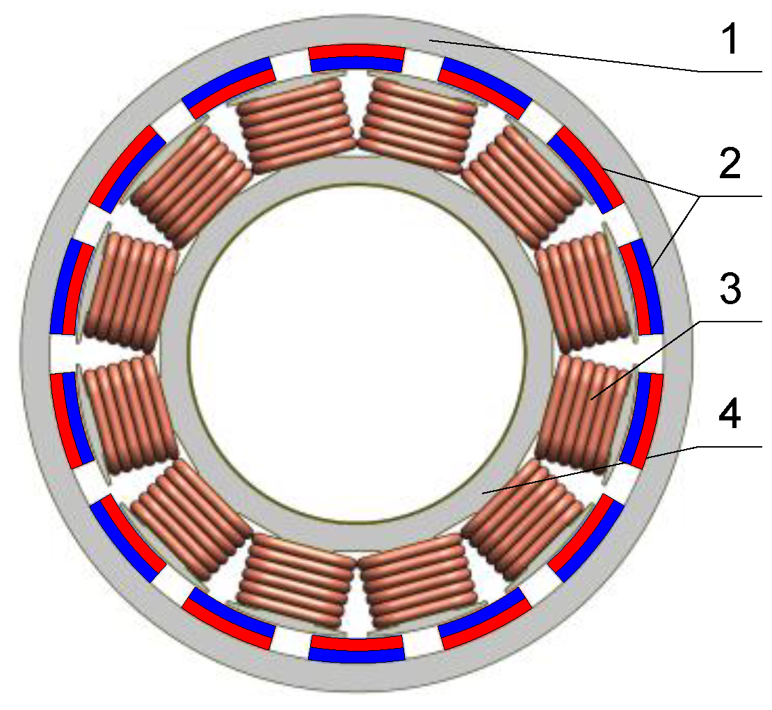
Figure 2.
Methodology of the ERPMSM design.

Figure 3.
Forces acting on a moving vehicle: FAD, total aerodynamic drag force; FT, traction force acting on the vehicle; FS, total sliding force; FTD, the force acting on the moving vehicle as a result of friction in the transmission system; FRR, rolling resistance forces; FM, traction force; FGR, weight of the vehicle; FN, normal force of the vehicle; TM, traction torque; α, road inclination.
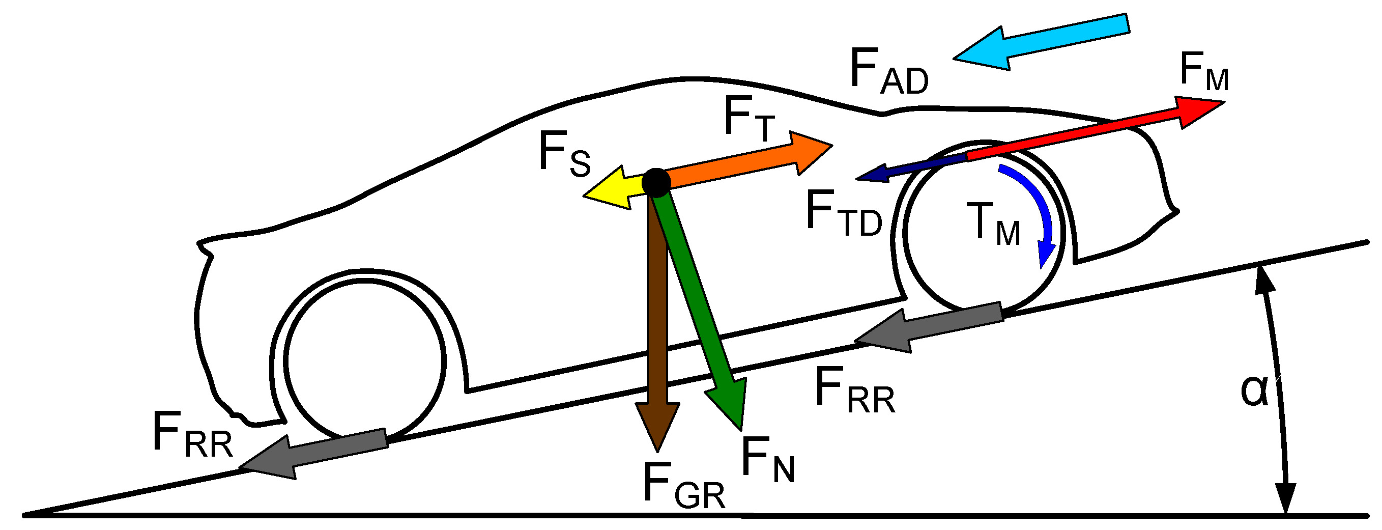
Figure 4.
Value of winding factor kW in relation to the combination of number of concentrated winding and number of magnets on the rotor.
Figure 4.
Value of winding factor kW in relation to the combination of number of concentrated winding and number of magnets on the rotor.
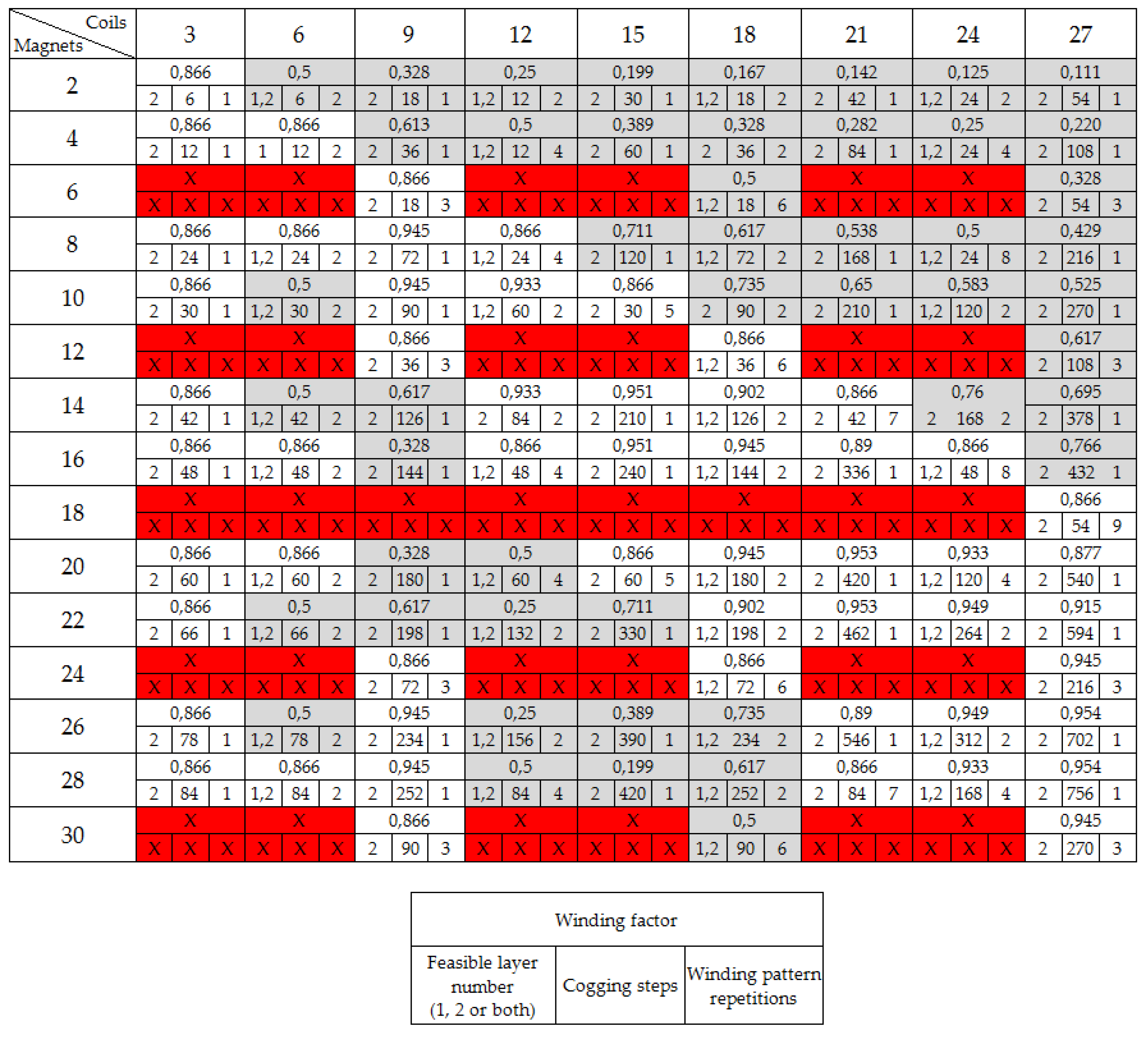
Figure 5.
View of ERPMSM with chosen geometric dimensions of the electromagnetic circuit.
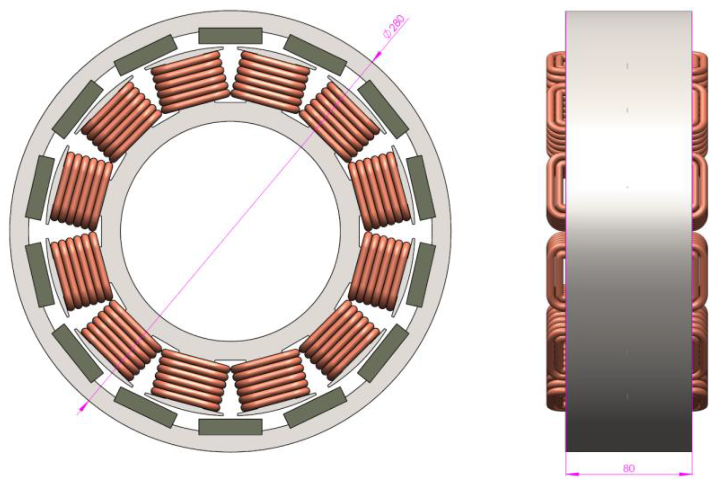
Figure 6.
Proposed shapes of magnets for the ERPMSM electric machine: (a) with arc magnets; (b) with lenticular magnets; (c) with prismatic rectangular magnets; and (d) with prismatic magnets with reinforcement by Halbach array.
Figure 6.
Proposed shapes of magnets for the ERPMSM electric machine: (a) with arc magnets; (b) with lenticular magnets; (c) with prismatic rectangular magnets; and (d) with prismatic magnets with reinforcement by Halbach array.
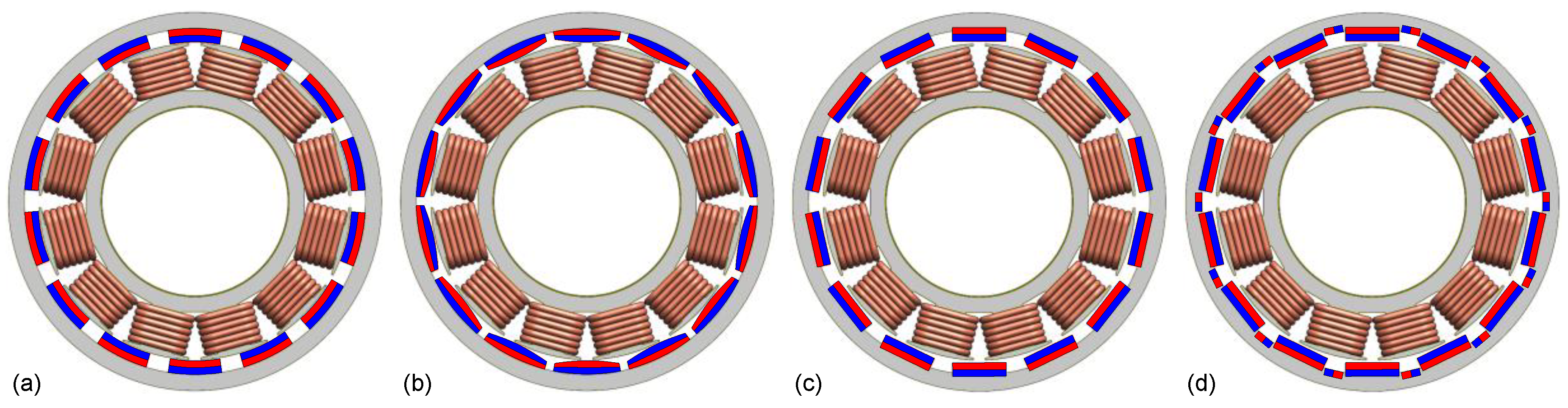
Figure 7.
Determination of the magnet length in relation to its angular measure in electrical degrees.
Figure 7.
Determination of the magnet length in relation to its angular measure in electrical degrees.
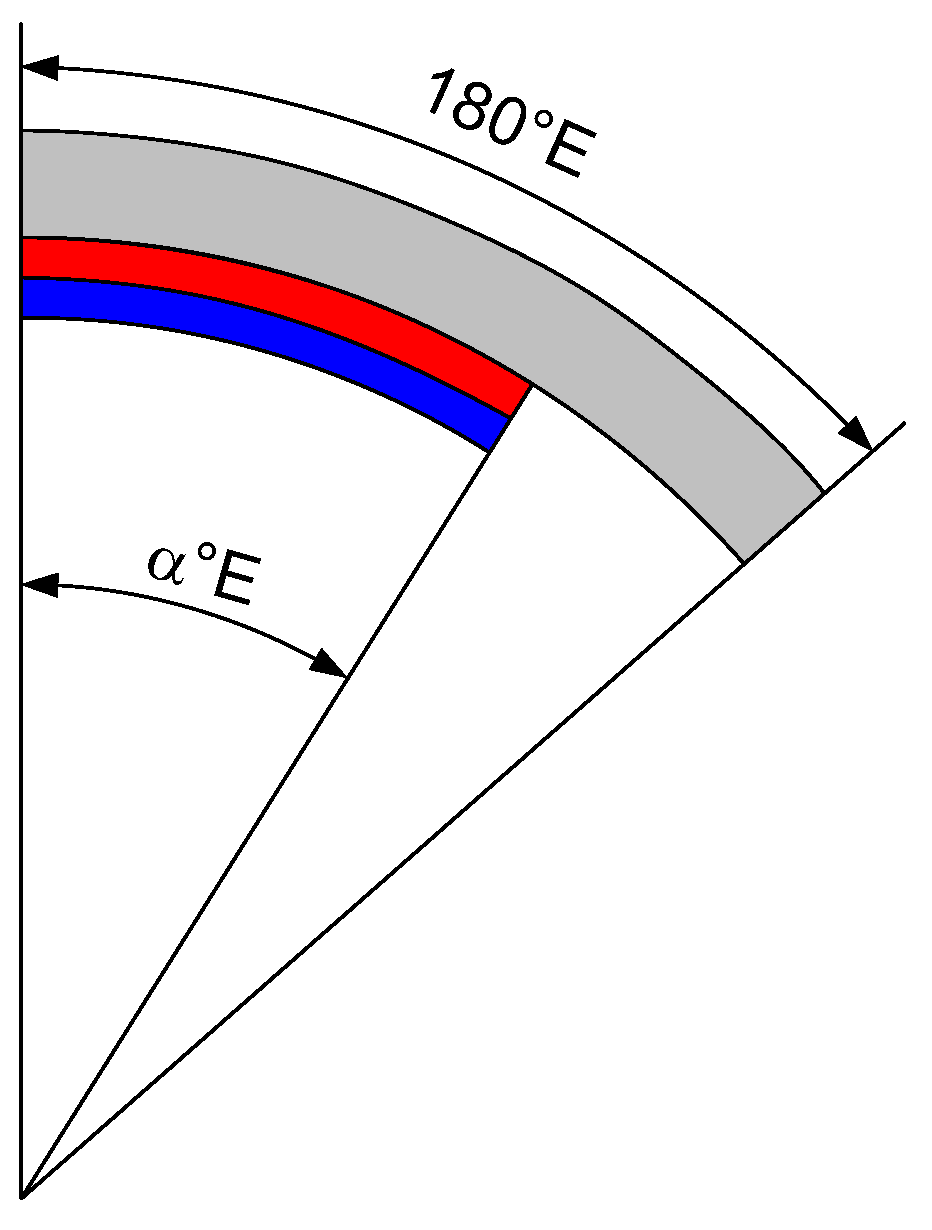
Figure 8.
The method of attaching flat magnets to the ERPMSM rotor: (a) flat on the rotor surface; (b) in milled recesses; (c) by hooks with large spacing; (d) by hooks with small spacing; (e) by hooks with no spacing; (f) in cavities buried beneath the rotor surface; (g) flat on the rotor surface using paramagnetic holders; (h) in milled recesses with reinforcement by Halbach array (short magnets); (i) in milled recesses with reinforcement by Halbach array (medium length magnets); and (j) in milled recesses with reinforcement by Halbach array (long magnets).

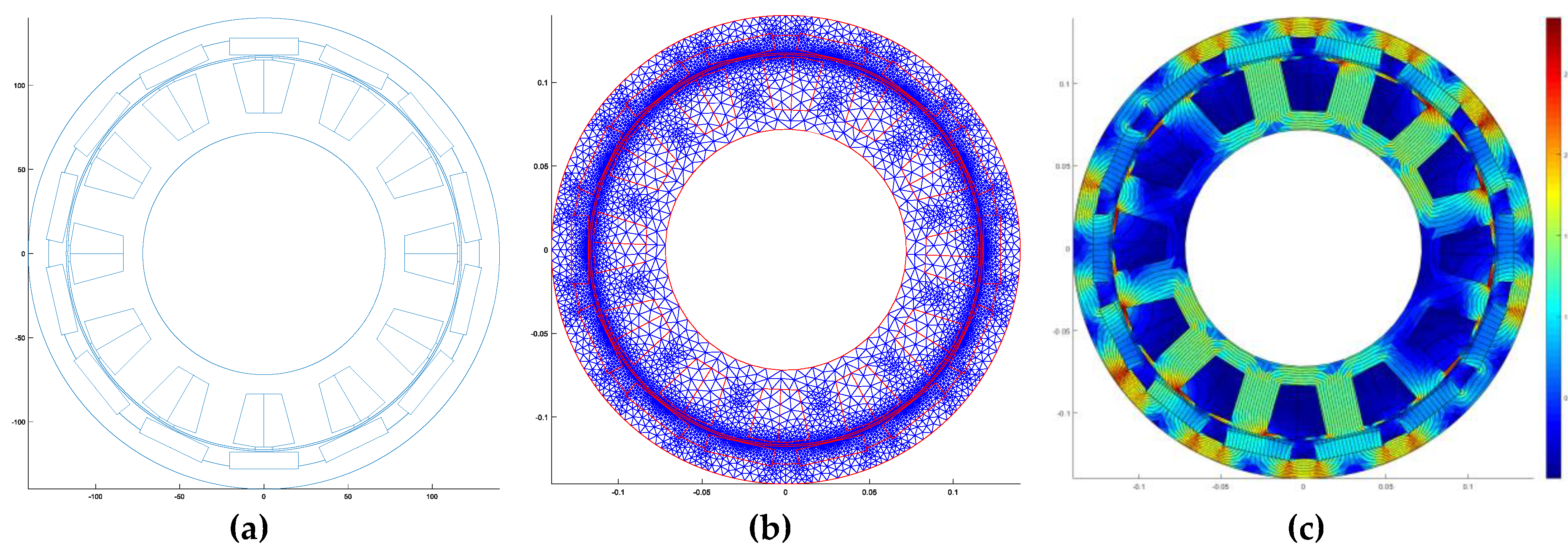
Figure 9.
An example view of ERPMSM with 12 concentrated coils and 14 magnets: (a) view of ERPMSM construction; (b) FEM triangle grid for motor calculations; and (c) magnetic field strength map B in the motor at a stator current of 150 A RMS.
Figure 9.
An example view of ERPMSM with 12 concentrated coils and 14 magnets: (a) view of ERPMSM construction; (b) FEM triangle grid for motor calculations; and (c) magnetic field strength map B in the motor at a stator current of 150 A RMS.

Figure 10.
A comparison of rotational speeds, torque and power developed by the motor depending on the method of mounting the magnets.
Figure 10.
A comparison of rotational speeds, torque and power developed by the motor depending on the method of mounting the magnets.
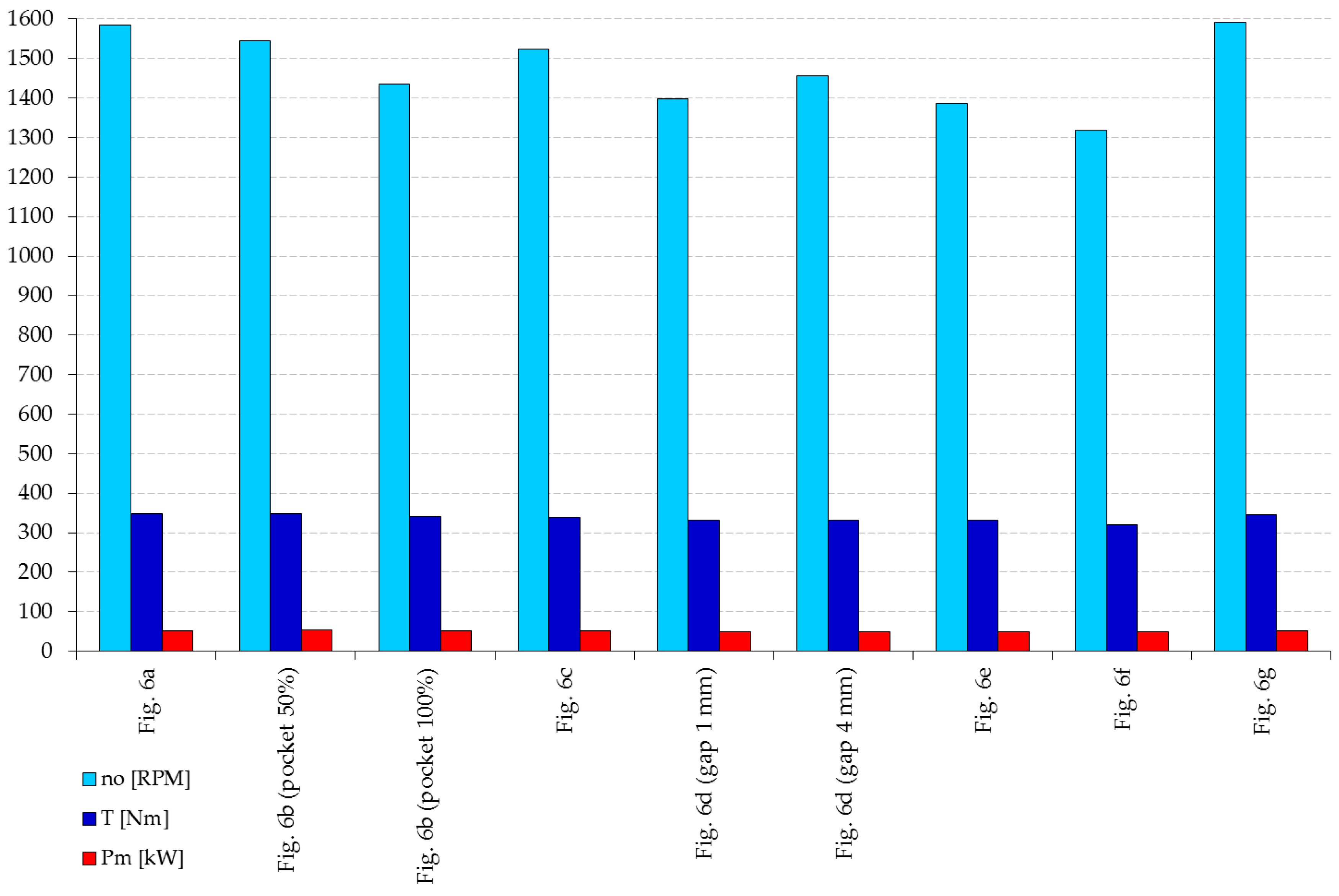
Figure 11.
Results obtained from performance calculations: (a) motor power; (b) shaft torque; (c) efficiency; (d) effective phase voltage; (e) cogging torque; and (f) torque ripple.
Figure 11.
Results obtained from performance calculations: (a) motor power; (b) shaft torque; (c) efficiency; (d) effective phase voltage; (e) cogging torque; and (f) torque ripple.
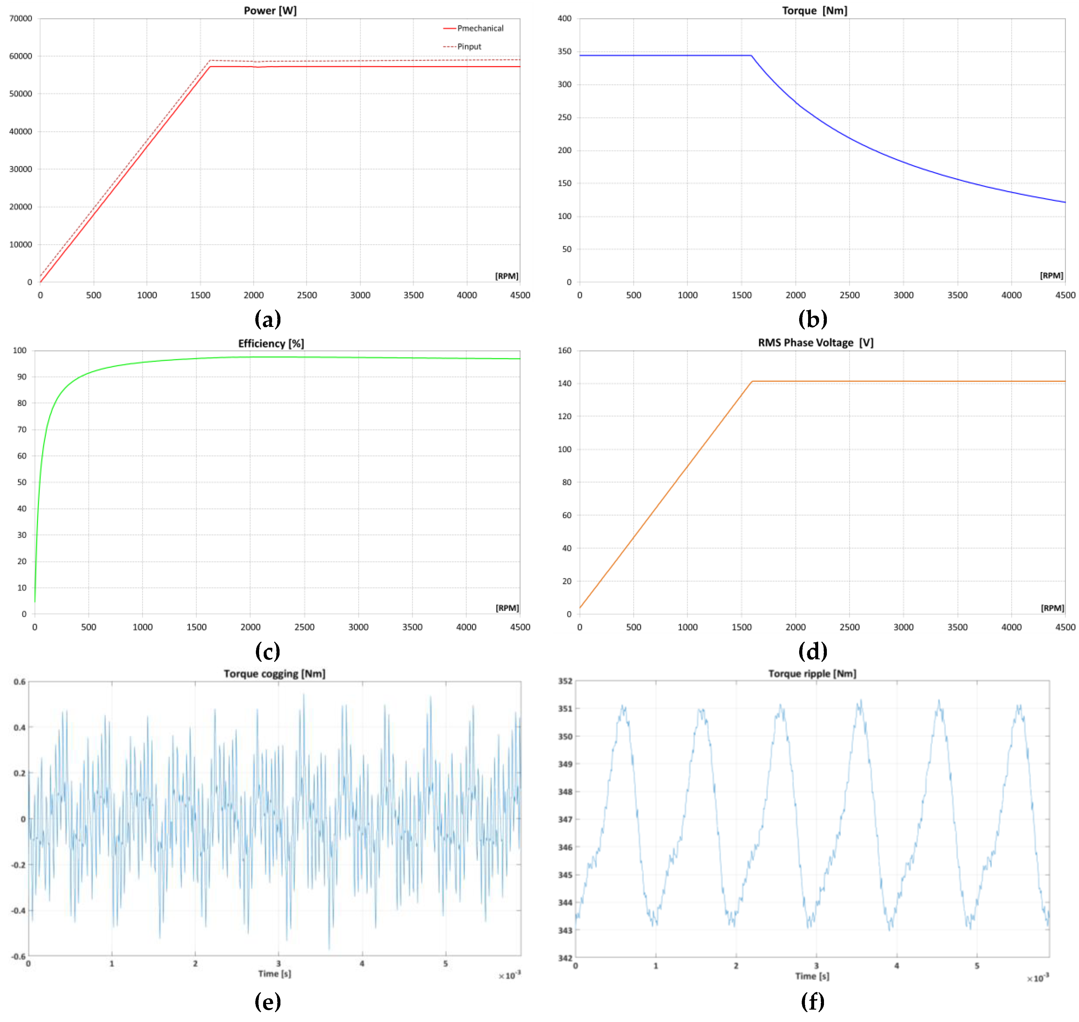
Figure 12.
Calculated performance maps of the ERPMSM: (a) motor efficiency map; (b) RMS phase current map; (c) RMS phase voltage map; (d) input power map; (e) required advance angle map (in electrical degrees); and (f) power factor map.
Figure 12.
Calculated performance maps of the ERPMSM: (a) motor efficiency map; (b) RMS phase current map; (c) RMS phase voltage map; (d) input power map; (e) required advance angle map (in electrical degrees); and (f) power factor map.

Table 1.
The results of initial numerical calculations of the motor with concentrated coils wound with 16 turns of wire with a CSA of 13.4 [mm2].
Table 1.
The results of initial numerical calculations of the motor with concentrated coils wound with 16 turns of wire with a CSA of 13.4 [mm2].
| Magnet shape (ref. Figure 6) | U (V) | URMS (V) | n0 (RPM) | T (Nm) | TP (Nm) | ηmax (%) | PM (kW) | PCu (kW) | PFe (kW) |
|---|---|---|---|---|---|---|---|---|---|
| Arc 4a, 66.7% | 141.4 | 123.3 | 1659 | 346 | 4.3 | 96.89 | 50.49 | 1.62 | 0.106 |
| Lenticular 4b, 66.7% | 141.4 | 119.7 | 1713 | 317 | 2.6 | 96.55 | 48.19 | 1.62 | 0.099 |
| Prismatic 4c, 66.7% | 141.4 | 122.3 | 1676 | 332 | 5 | 96.69 | 50.35 | 1.62 | 0.099 |
| Halbach 4d, 66.7% | 141.4 | 130.3 | 1570 | 360 | 6.8 | 97.11 | 54.67 | 1.62 | 0.113 |
Table 2.
The results of initial numerical calculations of the motor with concentrated coils with 17 turns of wire with a CSA of 12.8 [mm2].
Table 2.
The results of initial numerical calculations of the motor with concentrated coils with 17 turns of wire with a CSA of 12.8 [mm2].
| Magnet shape (ref. Figure 6) | U (V) | URMS (V) | n0 (RPM) | T (Nm) | TP (Nm) | ηmax (%) | PM (kW) | PCu (kW) | PFe (kW) |
|---|---|---|---|---|---|---|---|---|---|
| Arc 4a, 66.7% | 141.4 | 132.4 | 1549 | 352 | 4.5 | 96.76 | 53.42 | 1.68 | 0.107 |
| Lenticular 4b, 66.7% | 141.4 | 128.5 | 1595 | 336 | 2.7 | 96.62 | 50.96 | 1.68 | 0.101 |
| Prismatic 4c, 66.7% | 141.4 | 130.3 | 1573 | 351 | 5.3 | 97.37 | 53.27 | 1.68 | 0.100 |
| Halbach 4d, 66.7% | 141.4 | 139.9 | 1465 | 383 | 6 | 97.00 | 58.11 | 1.68 | 0.115 |
Table 3.
The influence of the length changes of the arc shaped magnets on the obtained ERPMSM parameters.
Table 3.
The influence of the length changes of the arc shaped magnets on the obtained ERPMSM parameters.
| Magnet Shape and Fill Percentage | U (V) | URMS (V) | n0 (RPM) | T (Nm) | TP (Nm) | ηmax (%) | PM (kW) | PCu (kW) | PFe (kW) |
|---|---|---|---|---|---|---|---|---|---|
| Arc 100°E, 55.6% | 141.4 | 122.8 | 1670 | 310 | 8.0 | 96.35 | 47.05 | 1.68 | 0.098 |
| Arc 110°E, 61.1% | 141.4 | 127.8 | 1601 | 332 | 8.7 | 96.58 | 50.44 | 1.68 | 0.103 |
| Arc 111°E, 61.7% (Golden Ratio) | 141.4 | 128.3 | 1598 | 335 | 8.5 | 96.61 | 50.82 | 1.68 | 0.104 |
| Arc 120°E, 66.7% | 141.4 | 132.4 | 1549 | 352 | 4.5 | 96.76 | 53.42 | 1.68 | 0.107 |
| Arc 130°E, 72.2% | 141.4 | 136.8 | 1499 | 369 | 10.0 | 96.9 | 56.07 | 1.68 | 0.111 |
| Arc 140°E, 77.8% | 141.4 | 140.7 | 1457 | 384 | 14.0 | 97.01 | 58.35 | 1.68 | 0.115 |
| Arc 150°E, 83.3% | 141.4 | 143.7 | 1424 | 396 | 11.8 | 97.09 | 60.12 | 1.68 | 0.118 |
| Arc 160°E, 88.9% | 141.4 | 145.9 | 1402 | 404 | 6.0 | 97.15 | 61.37 | 1.68 | 0.120 |
| Arc 170°E, 94.4% | 141.4 | 146.3 | 1398 | 407 | 20.0 | 97.16 | 61.81 | 1.68 | 0.121 |
Table 4.
The influence of radius changes on the surface of the lenticular magnets on the obtained ERPMSM parameters.
Table 4.
The influence of radius changes on the surface of the lenticular magnets on the obtained ERPMSM parameters.
| Description | U (V) | URMS (V) | n0 (RPM) | T (Nm) | TP (Nm) | ηmax (%) | PM (kW) | PCu (kW) | PFe (kW) |
|---|---|---|---|---|---|---|---|---|---|
| Lent. R62, 66.7% | 141.4 | 124.7 | 1644 | 319 | 1.4 | 96.46 | 48.41 | 1.68 | 0.097 |
| Lent. R112, 66.7% | 141.4 | 128.5 | 1595 | 336 | 2.7 | 96.62 | 50.96 | 1.68 | 0.101 |
| Lent. R282, 66.7% | 141.4 | 131.5 | 1559 | 348 | 3.8 | 96.73 | 52.83 | 1.68 | 0.104 |
Table 5.
The effect of changes in the length of prismatic magnets on the obtained ERPMSM parameters.
Table 5.
The effect of changes in the length of prismatic magnets on the obtained ERPMSM parameters.
| Description | U (V) | URMS (V) | n0 (RPM) | T (Nm) | TP (Nm) | ηmax (%) | PM (kW) | PCu (kW) | PFe (kW) |
|---|---|---|---|---|---|---|---|---|---|
| Flat 100°E, 55.6% | 141.4 | 119.9 | 1706 | 298 | 5.0 | 96.22 | 45.26 | 1.68 | 0.094 |
| Flat 110°E, 61.1% | 141.4 | 123.8 | 1653 | 317 | 2.9 | 96.44 | 48.19 | 1.68 | 0.096 |
| Flat 114.66, 63.7% | 141.4 | 125.4 | 1632 | 325 | 2.5 | 96.52 | 49.38 | 1.68 | 0.098 |
| Flat 120°E, 66.7% | 141.4 | 130.3 | 1573 | 351 | 5.3 | 97.37 | 53.27 | 1.68 | 0.100 |
| Flat 130°E, 72.2% | 141.4 | 130.1 | 1573 | 346 | 4.8 | 96.72 | 52.61 | 1.68 | 0.100 |
| Flat 140°E, 77.8% | 141.4 | 131.9 | 1559 | 356 | 5.4 | 96.80 | 54.00 | 1.68 | 0.101 |
| Flat 150°E, 83.3% | 141.4 | 132.4 | 1545 | 360 | 4.5 | 96.84 | 54.68 | 1.68 | 0.101 |
| Flat 160°E, 88.9% | 141.4 | 131.5 | 1556 | 359 | 2.7 | 96.84 | 54.56 | 1.68 | 0.100 |
| Flat 170°E, 94.4% | 141.4 | 129.5 | 1580 | 354 | 1.6 | 96.80 | 53.78 | 1.68 | 0.098 |
Table 6.
The effect of thickness changes of prismatic magnets on the obtained ERPMSM parameters.
| Description | U (V) | URMS (V) | n0 (RPM) | T (Nm) | TP (Nm) | ηmax (%) | PM (kW) | PCu (kW) | PFe (kW) |
|---|---|---|---|---|---|---|---|---|---|
| Flat 120°E, 6 [mm] | 141.4 | 134.0 | 1527 | 313 | 5.1 | 96.38 | 47.56 | 1.68 | 0.104 |
| Flat 120°E, 8 [mm] | 141.4 | 132.1 | 1549 | 338 | 5.6 | 96.64 | 51.38 | 1.68 | 0.103 |
| Flat 120°E, 10 [mm] | 141.4 | 130.3 | 1573 | 351 | 5.3 | 97.37 | 53.27 | 1.68 | 0.100 |
| Flat 120°E, 12 [mm] | 141.4 | 126.3 | 1620 | 347 | 5.0 | 96.75 | 53.13 | 1.68 | 0.095 |
| Flat 120°E, 14 [mm] | 141.4 | 116.3 | 1759 | 322 | 4.3 | 96.51 | 48.90 | 1.68 | 0.085 |
Table 7.
Influence of the flat magnet attachment method on the obtained ERPMSM parameters.
| Description | U (V) | URMS (V) | n0 (RPM) | T (Nm) | TP (Nm) | ηmax (%) | PM (kW) | PCu (kW) | PFe (kW) |
|---|---|---|---|---|---|---|---|---|---|
| Ref. Fig. 6a | 141.4 | 129.4 | 1584 | 348 | 5 | 96.74 | 52.91 | 1.68 | 0.099 |
| Ref. Fig. 6b (recess depth 50%) | 141.4 | 132.7 | 1545 | 349 | 5 | 96.75 | 53.01 | 1.68 | 0.100 |
| Ref. Fig. 6b (recess depth 100%) | 141.4 | 142.9 | 1435 | 340 | 2.5 | 96.65 | 51.62 | 1.68 | 0.106 |
| Ref. Fig. 6c | 141.4 | 134.5 | 1524 | 338 | 2.5 | 96.65 | 51.41 | 1.68 | 0.101 |
| Ref. Fig. 6d (gap width 1 mm) | 141.4 | 146.6 | 1399 | 332 | 4 | 96.57 | 50.48 | 1.68 | 0.113 |
| Ref. Fig. 6d (gap width 4 mm) | 141.4 | 140.7 | 1457 | 332 | 4 | 96.57 | 50.36 | 1.68 | 0.108 |
| Ref. Fig. 6e | 141.4 | 147.9 | 1386 | 332 | 4 | 96.56 | 50.39 | 1.68 | 0.133 |
| Ref. Fig. 6f | 141.4 | 155.5 | 1318 | 319 | 1.8 | 96.40 | 48.49 | 1.68 | 0.092 |
| Ref. Fig. 6g | 141.4 | 128.9 | 1591 | 346 | 5 | 96.72 | 52.53 | 1.68 | 0.097 |
Table 8.
Impact of applying various ferromagnetic materials for stator construction on the obtained ERPMSM parameters.
Table 8.
Impact of applying various ferromagnetic materials for stator construction on the obtained ERPMSM parameters.
| Description | U (V) | URMS (V) | n0 (RPM) | T (Nm) | TP (Nm) | ηmax (%) | PM (kW) | PCu (kW) | PFe (kW) |
|---|---|---|---|---|---|---|---|---|---|
| M400–50A | 141.4 | 131.1 | 1564 | 351 | 5.5 | 96.65 | 53.35 | 1.68 | 0.168 |
| M350–50A | 141.4 | 131.2 | 1559 | 351 | 5.5 | 96.65 | 53.36 | 1.68 | 0.168 |
| M330–50A | 141.4 | 131.2 | 1563 | 352 | 5.6 | 96.68 | 53.39 | 1.68 | 0.150 |
| M330–35A | 141.4 | 131.2 | 1563 | 352 | 5.6 | 96.70 | 53.40 | 1.68 | 0.138 |
| M300–35A | 141.4 | 131.1 | 1561 | 351 | 5.4 | 96.74 | 53.33 | 1.68 | 0.117 |
| M270–35A | 141.4 | 131.0 | 1562 | 351 | 5.4 | 96.75 | 53.31 | 1.68 | 0.108 |
| M250–35A | 141.4 | 131.0 | 1562 | 351 | 5.3 | 96.76 | 53.29 | 1.68 | 0.105 |
| M235–35A | 141.4 | 130.3 | 1573 | 351 | 5.3 | 97.37 | 53.27 | 1.68 | 0.100 |
Table 9.
Impact of using various ferromagnetic materials to build the rotor on the obtained ERPMSM parameters.
Table 9.
Impact of using various ferromagnetic materials to build the rotor on the obtained ERPMSM parameters.
| Description | U (V) | URMS (V) | n0 (RPM) | T (Nm) | TP (Nm) | ηmax (%) | PM (kW) | PCu (kW) | PFe (kW) |
|---|---|---|---|---|---|---|---|---|---|
| 1010 AISI 0.1%C | 141.4 | 130.2 | 1575 | 349 | 5.2 | 96.75 | 53.00 | 1.68 | 0.099 |
| M400–50A | 141.4 | 128.4 | 1597 | 345 | 5.0 | 96.7169 | 52.3781 | 1.68 | 0.0960538 |
| M235–35A | 141.4 | 128.4 | 1597 | 345 | 5.0 | 96.7168 | 52.3791 | 1.68 | 0.0961179 |
| ARMCO | 141.4 | 130.3 | 1573 | 351 | 5.3 | 97.37 | 53.27 | 1.68 | 0.100 |
Table 10.
Impact of the use of magnets made of various magnetic materials on the obtained ERPMSM parameters.
Table 10.
Impact of the use of magnets made of various magnetic materials on the obtained ERPMSM parameters.
| Description | U (V) | URMS (V) | n0 (RPM) | T (Nm) | TP (Nm) | ηmax (%) | PM (kW) | PCu (kW) | PFe (kW) |
|---|---|---|---|---|---|---|---|---|---|
| N30UH | 141.4 | 123.6 | 1655 | 320 | 5.0 | 96.47 | 48.57 | 1.68 | 0.093 |
| N35UH | 141.4 | 128.3 | 1598 | 340 | 5.2 | 96.67 | 51.64 | 1.68 | 0.098 |
| N38UH | 141.4 | 130.3 | 1573 | 351 | 5.3 | 97.37 | 53.27 | 1.68 | 0.100 |
| N42UH | 141.4 | 133.9 | 1531 | 364 | 5.3 | 96.87 | 55.23 | 1.68 | 0.104 |
| N45UH | 141.4 | 136.0 | 1508 | 372 | 5.3 | 96.93 | 56.48 | 1.68 | 0.106 |
Table 11.
The effect of skewing the rotor magnets on the obtained ERPMSM parameters.
| Description | U (V) | URMS (V) | n0 (RPM) | T (Nm) | TP (Nm) | ηmax (%) | PM (kW) | PCu (kW) | PFe (kW) |
|---|---|---|---|---|---|---|---|---|---|
| Rotor skew 1° | 141.4 | 130.9 | 1566 | 350 | 4.0 | 96.76 | 53.23 | 1.68 | 0.100 |
| Rotor skew 2° | 141.4 | 130.6 | 1570 | 350 | 3.0 | 96.75 | 53.09 | 1.68 | 0.100 |
| Rotor skew 3° | 141.4 | 130.2 | 1575 | 348 | 1.5 | 96.74 | 52.86 | 1.68 | 0.099 |
| Rotor skew 3.25° | 141.4 | 130.0 | 1577 | 348 | 1.4 | 96.74 | 52.79 | 1.68 | 0.099 |
| Rotor skew 3.5° | 141.4 | 129.9 | 1578 | 347 | 0.9 | 96.73 | 52.72 | 1.68 | 0.098 |
| Rotor skew 3.75° | 141.4 | 129.8 | 1580 | 347 | 0.5 | 96.73 | 52.64 | 1.68 | 0.098 |
| Rotor skew 4° | 141.4 | 129.6 | 1582 | 346 | 0.7 | 96.72 | 52.55 | 1.68 | 0.098 |
| Rotor skew 5° | 141.4 | 128.9 | 1591 | 343 | 1.36 | 96.70 | 52.15 | 1.68 | 0.097 |
| Rotor skew 6° | 141.4 | 128.0 | 1602 | 340 | 1.4 | 96.67 | 51.66 | 1.68 | 0.095 |
| Rotor skew 7° | 141.4 | 127.0 | 1614 | 336 | 1.1 | 96.64 | 51.10 | 1.68 | 0.094 |
| Rotor skew 8° | 141.4 | 125.8 | 1630 | 332 | 1.03 | 96.00 | 50.45 | 1.68 | 0.092 |
| Rotor skew 9° | 141.4 | 124.5 | 1647 | 327 | 1.4 | 96.56 | 49.73 | 1.68 | 0.090 |
| Rotor skew 10° | 141.4 | 123.1 | 1666 | 322 | 1.3 | 96.51 | 48.93 | 1.68 | 0.088 |
Table 12.
The effect of twisting the stator coils on the obtained ERPMSM parameters.
| Description | U (V) | URMS (V) | n0 (RPM) | T (Nm) | TP (Nm) | ηmax (%) | PM (kW) | PCu (kW) | PFe (kW) |
|---|---|---|---|---|---|---|---|---|---|
| Stator skew 1° | 141.4 | 130.9 | 1566 | 350 | 4.0 | 96.76 | 53.23 | 1.68 | 0.100 |
| Stator skew 2° | 141.4 | 130.6 | 1570 | 350 | 3.2 | 96.75 | 53.10 | 1.68 | 0.100 |
| Stator skew 3° | 141.4 | 130.2 | 1575 | 348 | 1.5 | 96.74 | 52.87 | 1.68 | 0.099 |
| Stator skew 3.25° | 141.4 | 130.1 | 1576 | 348 | 1.3 | 96.74 | 52.81 | 1.68 | 0.099 |
| Stator skew 3.5° | 141.4 | 129.9 | 1578 | 347 | 0.9 | 96.73 | 52.73 | 1.68 | 0.098 |
| Stator skew 3.75° | 141.4 | 129.8 | 1580 | 347 | 0.6 | 96.73 | 52.65 | 1.68 | 0.098 |
| Stator skew 4° | 141.4 | 129.6 | 1582 | 346 | 1.2 | 96.72 | 52.57 | 1.68 | 0.098 |
| Stator skew 5° | 141.4 | 128.9 | 1591 | 344 | 1.3 | 96.70 | 52.18 | 1.68 | 0.097 |
| Stator skew 6° | 141.4 | 128.1 | 1597 | 340 | 1.57 | 96.67 | 51.71 | 1.68 | 0.096 |
| Stator skew 7° | 141.4 | 127.1 | 1610 | 337 | 1.16 | 96.64 | 51.16 | 1.68 | 0.094 |
| Stator skew 8° | 141.4 | 126.0 | 1624 | 333 | 0.94 | 96.60 | 50.53 | 1.68 | 0.093 |
| Stator skew 9° | 141.4 | 124.7 | 1641 | 328 | 1.41 | 96.56 | 49.82 | 1.68 | 0.091 |
| Stator skew 10° | 141.4 | 123.3 | 1659 | 323 | 1.40 | 96.49 | 49.04 | 1.68 | 0.089 |
Table 13.
Final results of simulation tests obtained for ERPMSM.
| Description | U (V) | URMS (V) | n0 (RPM) | T (Nm) | TP (Nm) | ηmax (%) | PM (kW) | PCu (kW) | PFe (kW) |
|---|---|---|---|---|---|---|---|---|---|
| ERPMSM | 141.4 | 141.4 | 1550 | 347 | 0.6 | 96.73 | 57.2 | 1.68 | 0.098 |
© 2018 by the author. Licensee MDPI, Basel, Switzerland. This article is an open access article distributed under the terms and conditions of the Creative Commons Attribution (CC BY) license (http://creativecommons.org/licenses/by/4.0/).
Share and Cite
MDPI and ACS Style
Łebkowski, A. Design, Analysis of the Location and Materials of Neodymium Magnets on the Torque and Power of In-Wheel External Rotor PMSM for Electric Vehicles. Energies 2018, 11, 2293. https://doi.org/10.3390/en11092293
AMA Style
Łebkowski A. Design, Analysis of the Location and Materials of Neodymium Magnets on the Torque and Power of In-Wheel External Rotor PMSM for Electric Vehicles. Energies. 2018; 11(9):2293. https://doi.org/10.3390/en11092293
Chicago/Turabian StyleŁebkowski, Andrzej. 2018. "Design, Analysis of the Location and Materials of Neodymium Magnets on the Torque and Power of In-Wheel External Rotor PMSM for Electric Vehicles" Energies 11, no. 9: 2293. https://doi.org/10.3390/en11092293
Note that from the first issue of 2016, this journal uses article numbers instead of page numbers. See further details here.