Disturbance-Observer-Based Model Predictive Control for Battery Energy Storage System Modular Multilevel Converters

1
School of Electrical Engineering, Southeast University, Nanjing 210096, China
2
Key Laboratory of Measurement and Control of Complex Systems of Engineering, Ministry of Education, School of Automation, Southeast University, Nanjing 210096, China
*
Author to whom correspondence should be addressed.
Energies 2018, 11(9), 2285; https://doi.org/10.3390/en11092285
Submission received: 31 July 2018
/
Revised: 14 August 2018
/
Accepted: 28 August 2018
/
Published: 30 August 2018
(This article belongs to the Special Issue Communications in Microgrids)
Abstract
:Although the traditional model predictive control (MPC) can theoretically provide AC current and circulating current control for modular multilevel converters (MMCs) in battery energy storage grid-connected systems, it suffers from stability problems due to the power quality of the power grid and model parameter mismatches. A two discrete-time disturbance observers (DOBs)-based MPC strategy is investigated in this paper to solve this problem. The first DOB is used to improve the AC current quality and the second enhances the stability of the circulating current control. The distortion and fluctuation of grid voltage and inductance parameter variation are considered as lump disturbances in the discrete modeling of a MMC. Based on the proposed method, the output prediction is compensated by disturbance estimation to correct the AC current and circulating current errors, which eventually achieve the expected tracking performance. Moreover, the DOBs have a quite low computational cost with minimum order and optimal performance properties. Since the designed DOBs work in parallel with the MPC, the control effect is improved greatly under harmonics, 3-phase unbalance, voltage sag, inductance parameter mismatches and power reversal conditions. Simulation results confirm the validity of the proposed scheme.
1. Introduction
The increasing popularity of clean energy has prompted new attention to the stability of the power system because of its intermittent character. The microgrid based on battery energy storage can restrain the negative influences of renewable power supplies on the power grid. Therefore, it is significant to research the battery energy storage technology [1]. As the interface to the power grid, the grid-connected converter for battery energy storage system determines the effect of bidirectional power exchange, AC/DC current control and discharge/recharge [2,3,4]. However, there are various non-determinacies and disturbances that widely exist in the system, including harmonics, 3-phase unbalance, voltage sag from the power grid, and model parameter mismatches, etc. They usually have negative effects on the stability and performance of control systems [5,6,7,8].
Different types of converter topologies, containing the traditional two-level converter, multi-module converter, multilevel converter, and the newly recently advanced modular multilevel converter (MMC), have been presented and studied for battery storage converter applications [9,10,11,12,13]. Amid all the topology structures, the MMC is a recommended topology due to its merits such as high quality of the output voltage, flexible scaling of sub-modules (SMs), bidirectional power flow, and independent regulation of the active and reactive power [14,15]. These inherently salient features make the MMC ideally suited for battery energy storage systems.
Actually, the MMC system has the characteristics of large range of operational points and highly nonlinearity, which leads to the urgent need to design effective controllers and develop proper modulation techniques. Hence, many researchers have focused on the control issues of MMCs in recent years. In [16] a novel control method for a d-q frame based model of the MMC is proposed. Based on the reference values of six independent dynamical state variables, the MMC switching functions under steady state were obtained and a direct Lyapunov method was used to improve the dynamic components of those functions. A multi-loop control strategy based on a six-order dynamic model of the MMC was presented in [5] to ensure stable operation under both load and MMC parameters variations. In [17], differential flatness theory was employed to control a flat outputs-based dynamic model of the MMC innovatively, which greatly improves the MMC power sharing ability and enhances robustness. In addition, a novel modulation function-based controller which achieves two separate modulation functions to generate the switching signals of upper and lower SMs was proposed in [8,18]. This method not only maintains stable operation under varying parameter conditions, but also is easily applied.
However, the existing methods which need to modulate the switching signals are not straightforward and fast when compared with model predictive control (MPC) [19]. As a nonlinear control method, MPC is of great interest for MMC applications because of its simple modulation approach, flexible control goals and easy inclusion of nonlinearities. The best switch states are obtained by cost functions in the MPC method. Despite the excellent prospects and beneficial results obtained in the application of MPC to MMC, it is relatively slow due to its feedback regulation to asymptotically suppress the uncertainties and disturbances [20]. Thus, the control performance of the MPC is severely hindered in the presence of model uncertainties and external disturbances. Note that integral action is employed in MPC to eliminate the influences of uncertainties and disturbances [21], but the integrator would sacrifice original control effects because the integral term has coupled interactions with other properties, such as dynamic responses and stability.
The disturbance observer (DOB), an effective approach to compensate the effects of model uncertainties and external disturbances, is widely applied in electric power systems [22,23,24,25]. The main characteristic of DOB is that the robustness is achieved without sacrificing any of the original control performance [26]. In addition, this method does not need to establish an accurate mathematical model for the disturbance signals, and its structure is relatively simple, thus, the complicated calculations are avoided in the prediction of disturbance signals, which is beneficial to meet the requirements of real time applicability. In view of this, the combination of MPC with DOB has been extensively studied to improve the anti-disturbance capabilities of various systems, e.g., induction machine drives [24], permanent magnet synchronous motors [27], neutral-point-clamped multilevel converters [28], and three-phase inverters [6,7,29]. However, there are still many gaps in the MMC applications in battery energy storage systems.
As a grid-connected converter of a battery energy storage system, the grid voltage directly affects the control performance. The output current can be distorted by the power quality problems of the grid voltage such as harmonics, 3-phase unbalance and voltage sag. Then, the distorted current that is injected into the power grid would further damage the power quality. On the other hand, AC current control and circulating current suppression for MMC can be influenced by the varying parameters of resistances and inductances which are easily affected by temperature, frequency and electrical life. Hence, the control system needs effective real-time compensation for these uncertainties and disturbances [6,17].
In this paper, a MPC strategy with two linear discrete-time DOBs is proposed for an eleven-level MMC-based battery energy storage grid-connected converter. The MPC strategy divides the cost functions into three types, according to the three control objectives of AC current, circulating current and capacitor voltage-balancing [30]. Two DOBs are designed on the basis of the first two control purposes. The first DOB increases the anti-disturbance capacity of AC current control against the fluctuations of the grid voltage and inductance values. The second enhances the stability of circulating current control under the varying inductance value condition. The capacitor voltage-balancing control is the same as described in [30]. The main contributions of this paper include the following:
- (1)
- A MPC method based on prediction accuracy improvement via two DOBs is designed for a grid-connected MMCs of battery energy storage systems, which has a simple structure and quite low cost of computation with the minimum order.
- (2)
- The accurate estimation and feedforward compensation for disturbances are achieved without sacrificing the original control performance.
- (3)
- The disturbance items which act on the cost functions during each sampling period assure the cost functions always maintain optimal performance.
The studies are implemented based on time-domain simulations in the MATLAB/Simulink environment for five different operating conditions. Through the comparative results, it is validated that the proposed method works reliably even under power grid uncertainty and model parameter mismatch conditions.
2. MPC Strategy of the MMC
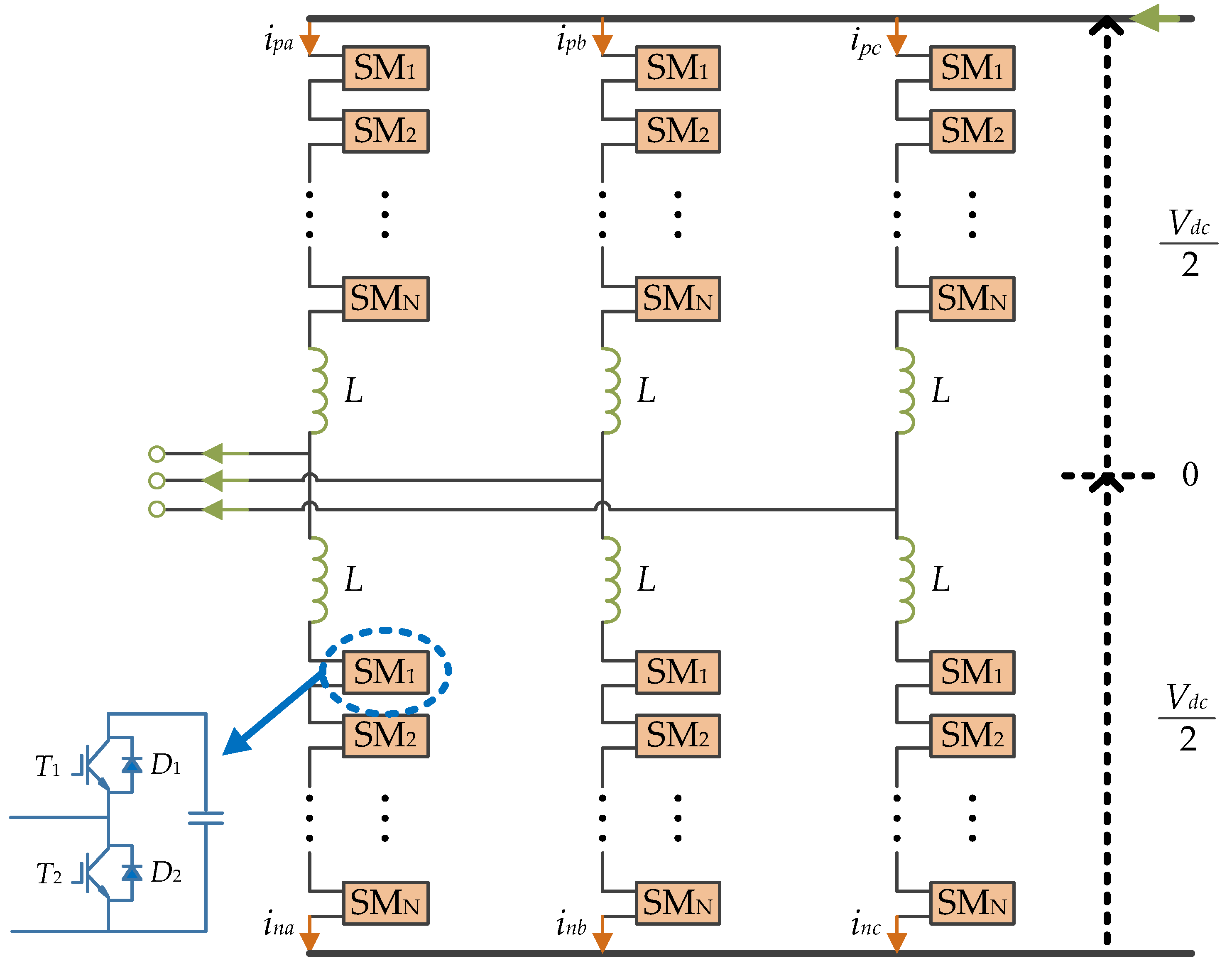
Figure 1 presents the circuit diagram of a 3-phase MMC, which is composed of two arms per phase. Each arm comprises N/2 series-connected half-bridge SMs, where N is the amount of SM per each phase, and a series inductor L. The SM consists of two IGBTs and one capacitor. The two switches (T1 and T2) per SM are controlled with complementary gating signals, resulting in two switch states which can input or bypass the capacitor. Thus, the voltage of the SM depends on the active switching states. The output voltage is the same as the capacitor when the SM is ON. In contrast, when it is OFF, the SM voltage turns to zero.
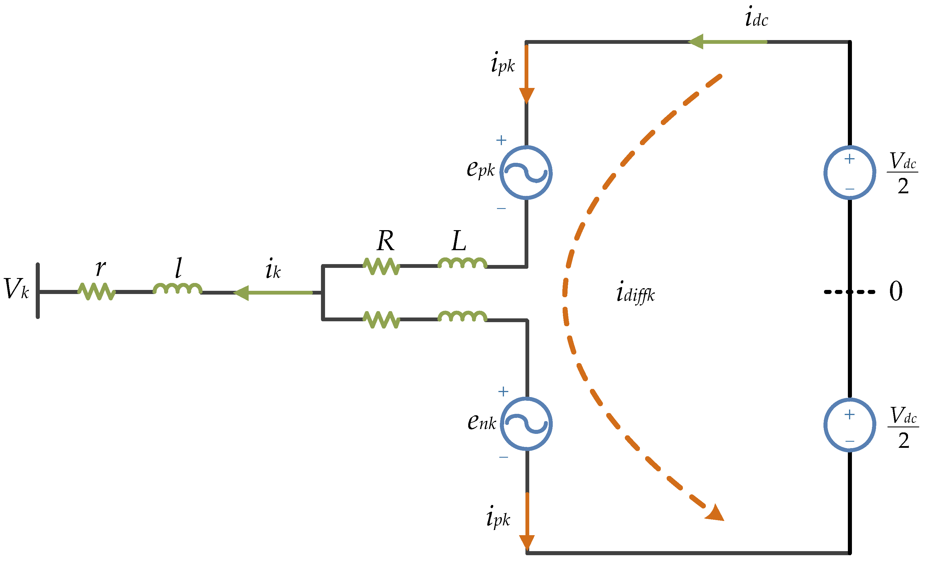
Figure 2 shows the equivalent model which is a simplification of 3-phase MMC presented in Figure 1. It describes one phase of the 3-phase MMC connected to the power grid across a filter inductor. The SMs in each arm are replaced by an AC power source and the DC-bus is equivalent to two DC power sources in series with the ground point.
Here, the upper-arm and lower-arm current are described by ipk and ink (k = a, b, c), respectively, where idiffk is the inner unbalanced current; Vk is the grid voltage; and epk and enk are the upper-arm and lower-arm voltage, respectively. The current that flows through the arms comprises the DC component and AC component of fundamental frequency in the ideal case, but the capacitor voltages are time-varying due to the AC current flow across the capacitors. As a result, there is a voltage difference between the arm voltage and DC voltage, which causes a circulating current in the converter [31].
The MPC method has three control objectives, thus, three cost functions are calculated according to them. They include: AC current control; circulating current suppression; and SM capacitor voltage balancing. In this paper, AC current control and circulating current suppression are considered and redesigned based on the disturbances and uncertainties of grid voltage and inductances.
2.1. MPC Strategy for AC Current
From Figure 2, the voltage equation of MMC can be expressed as follows:
where ; ; and is the converter output voltage, defined as:
where ; and .
The AC current are deduced in Equation (3) using the Euler forward equation:
where is the sampling period, which is considered extremely short.
The cost function can be designed by:
where is the AC current reference.
2.2. MPC Strategy for Circulating Current
The voltage and inner unbalanced current Equations are described as follows:
The inner unbalanced current is derived from the Euler forward equation:
Equation (2) shows that depends on the difference between upper-arm and lower-arm voltage. Thus, the same voltage added to and has no effect on the AC current. Hence, Equation (7) is rewritten as follows:
Two voltage levels are allocated to as in Equation (9). It can be expanded according to the characteristics of the circulating current:
Assuming there is no loss in MMC and the active power is controlled without ripples. The AC active power and DC active power of MMC are expressed as Equation (10) and the DC current reference is obtained as Equation (11) [32]. Thus, the cost function is designed as:
2.3. MPC Strategy for Capacitor Voltage Balancing
The SM capacitor voltage is calculated by:
where , with I = 1, 2, 3, …, N.
The cost function can be designed by:
3. MPC Strategy of the MMC with Disturbance Observer
The MPC controller could be affected by the disturbances caused by grid voltage and inductances. In this section, two DOB-based control structures are described to track the disturbances. The first DOB is designed to improve the waveform quality of AC current and the second is applied to suppress the circulating current. The DOBs to be designed are easy to assign the exponential stability of the estimation error dynamics and the order is minimal [33].
3.1. MPC Strategy for AC Current with DOB 1
Considering Equation (3) by neglecting the influence of resistances, letting:
where is a unknown value of disturbances in Equation (3) that needs to be observed; is the disturbances of system inductances; and is the disturbances of grid voltage.
Consequently, the model of Equation (3) can be expressed in a compact form as follows:
where ; ; ; and .
Thus, the first discrete-time disturbance observer is applied to estimate the disturbances of system (20), given by:
where is the estimated value of ; is the state variable of DOB 1; and is the coefficient of the pole assignment of DOB 1 to be designed.
Then, generally, the state estimation error, , has the dynamics:
where .
Letting , the estimation error is confined within a bound such that:
where ; and is a small positive value.
Hence, the coefficient of the pole assignment of DOB 1, can be given by:
3.2. MPC Strategy for Circulating Current with DOB 2
Considering Equation (8) by neglecting the influence of resistances, letting:
where is a unknown value of disturbances in Equation (8) that needs to be observed; and is the disturbances of arm inductances.
Similarly, the model (8) can be rewritten as follows:
where ; ; ; and .
Consequently, the second discrete-time disturbance observer is applied to system (29), given by:
where is the estimated value of ; is the state variable of DOB 2; and is the coefficient of the pole assignment of DOB 2.
Finally, the AC current and inner unbalanced current with DOBs can be given by:
In summary, and work as patches of MPC. They are decided by the actual system and equal to zero in the absence of disturbance and uncertainties. Thus, the DOB-based MPC control system would not be worse than the original MPC controller. On the other hand, they are calculated with the cost function simultaneously, which guarantees the cost functions always maintain their optimal performance no matter how the actual system chang.
4. Simulation Results
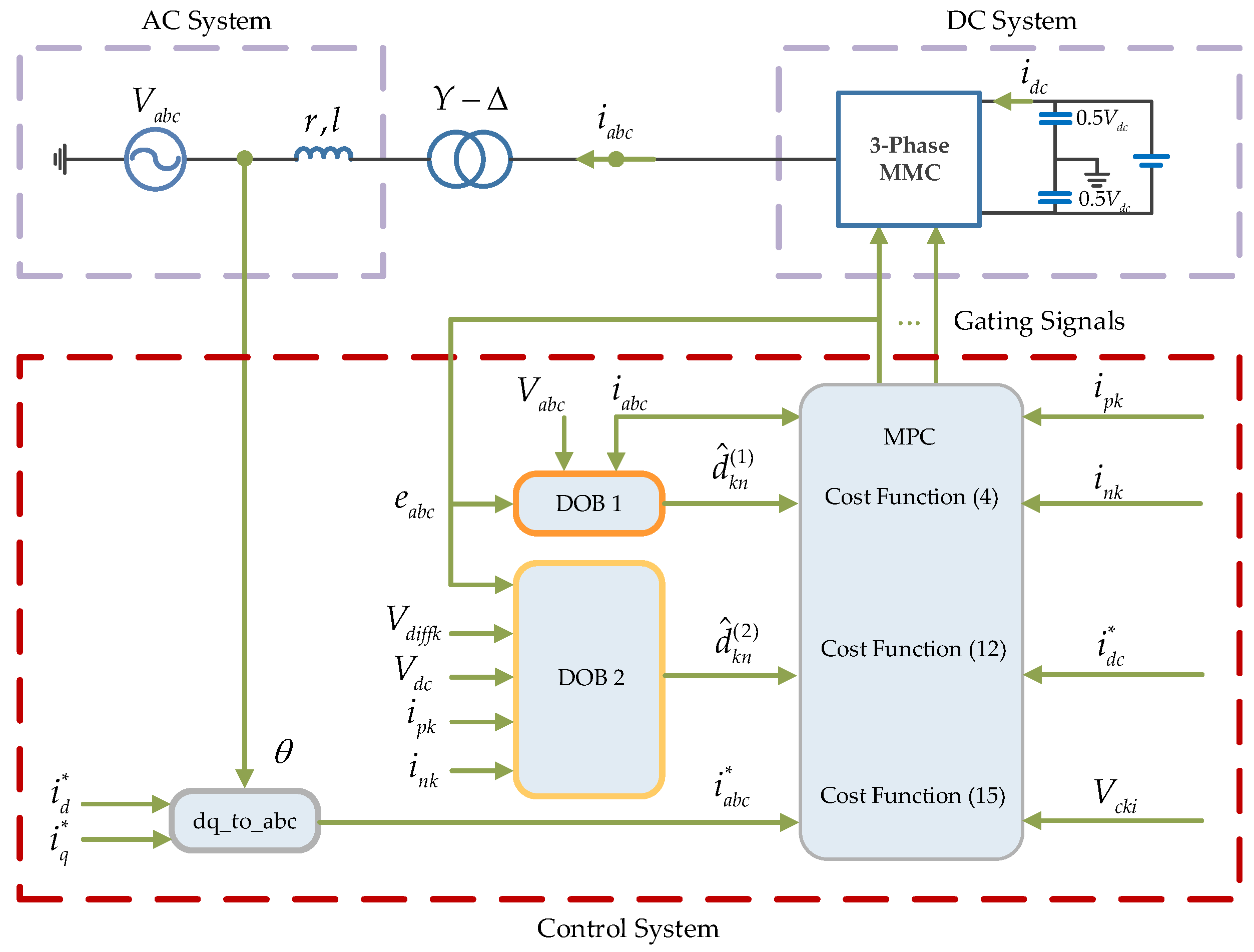
Simulations were carried out by using MATLAB/Simulink, and Figure 3 shows the structure of simulated system and proposed control method with DOBs. The critical parameters of circuit are reported in Table 1, and the Table 2 lists the control parameters of DOB 1 and DOB 2.
The MPC Strategy with DOB has been analyzed for five different test conditions:
- Harmonic: 3-phase grid voltage with 30% of 5th and 7th harmonics.
- 3-phase voltage unbalance: a-phase line-to-ground fault.
- Voltage sag: 3-phase grid voltage with 80% of reduction in the period of 0.01 s–0.03 s.
- Parameter mismatches: actual inductance values change.
- Power reversal: the power flow reverses from 0.05 s to 0.1 s; the 3-phase grid voltage contain harmonics and voltage sag; and the actual inductance values decline during the entire simulation time.
4.1. Simulations under Harmonic Condition
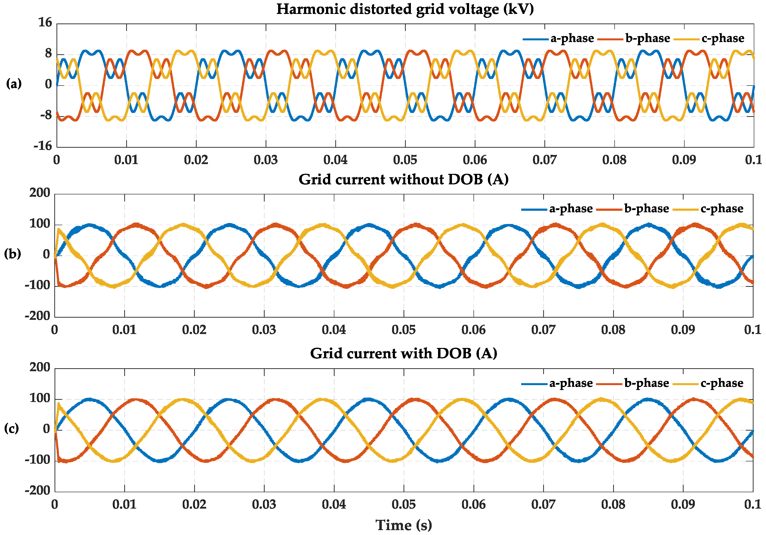
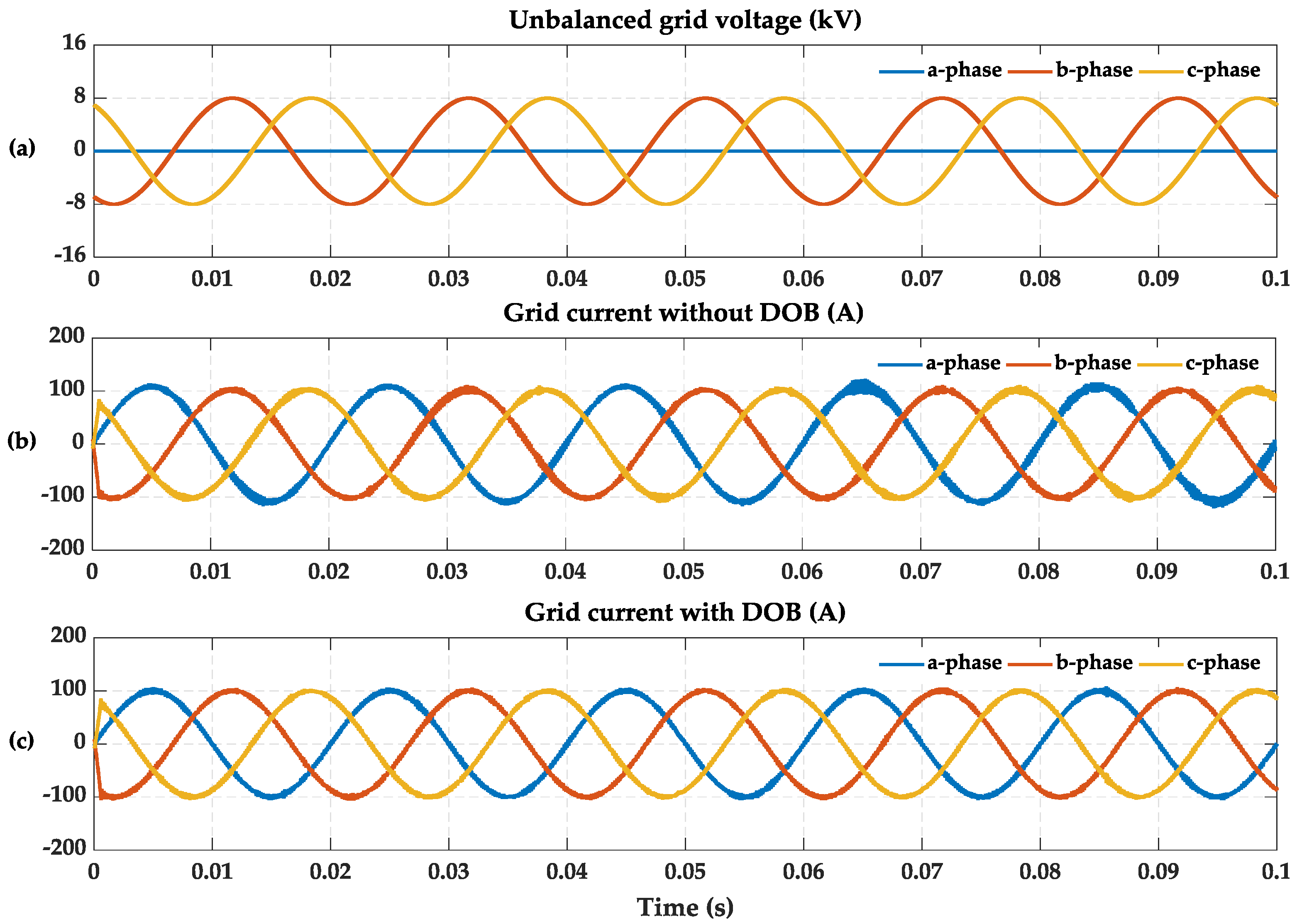
30% of 5th and 7th harmonics are overlaid onto the 3-phase grid voltage. The AC active current reference is 100 A, and the reactive current reference is 0 A. Figure 4a shows the 3-phase grid voltage with 5th and 7th harmonics. Figure 4b shows the 3-phase grid current without DOB. It is obvious from this figure that the grid current has been significantly distorted. The grid current is compensated by the proposed DOB as represented in Figure 4c. Compared with the Figure 4b, it can be seen that the harmonic current is effectively suppressed.
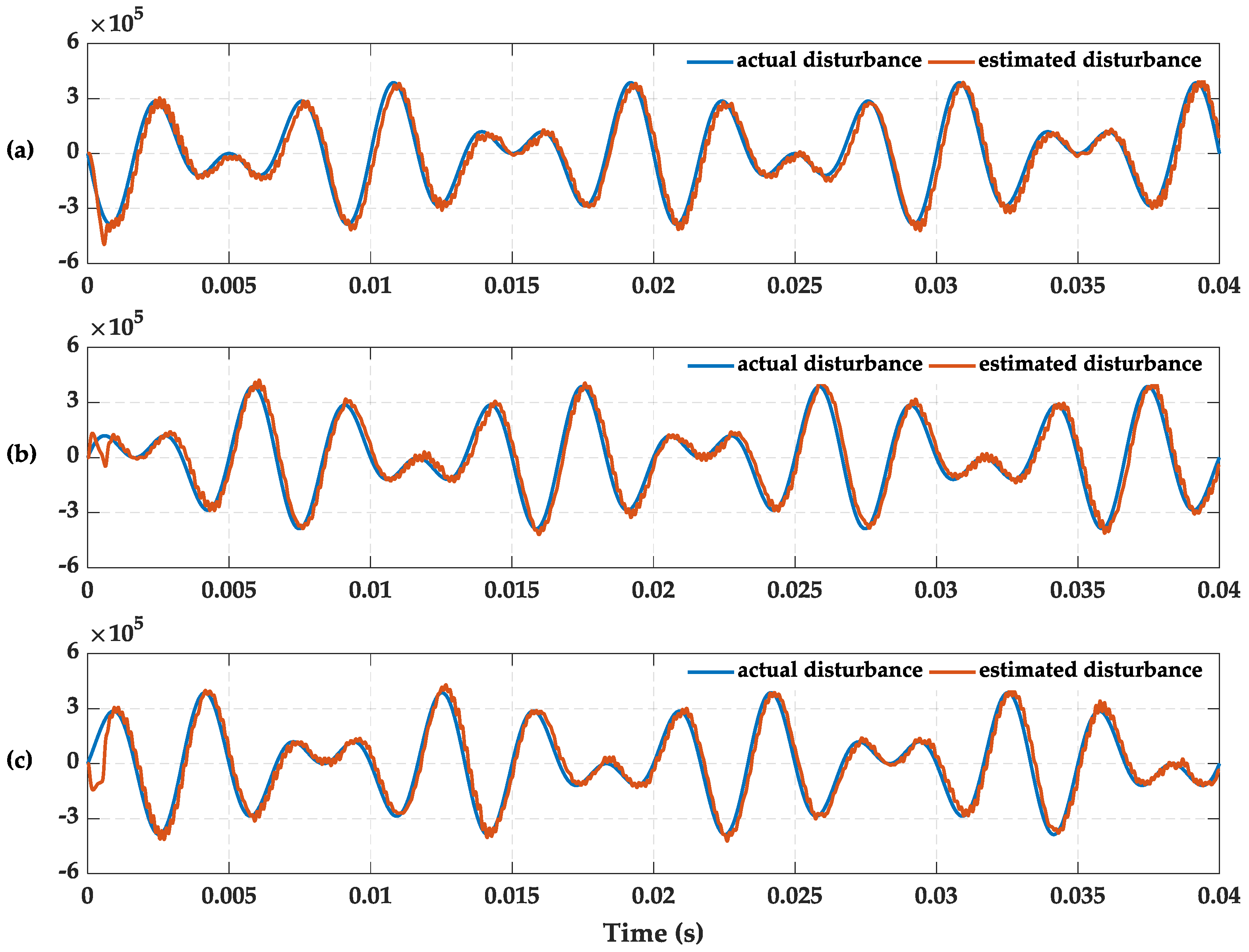
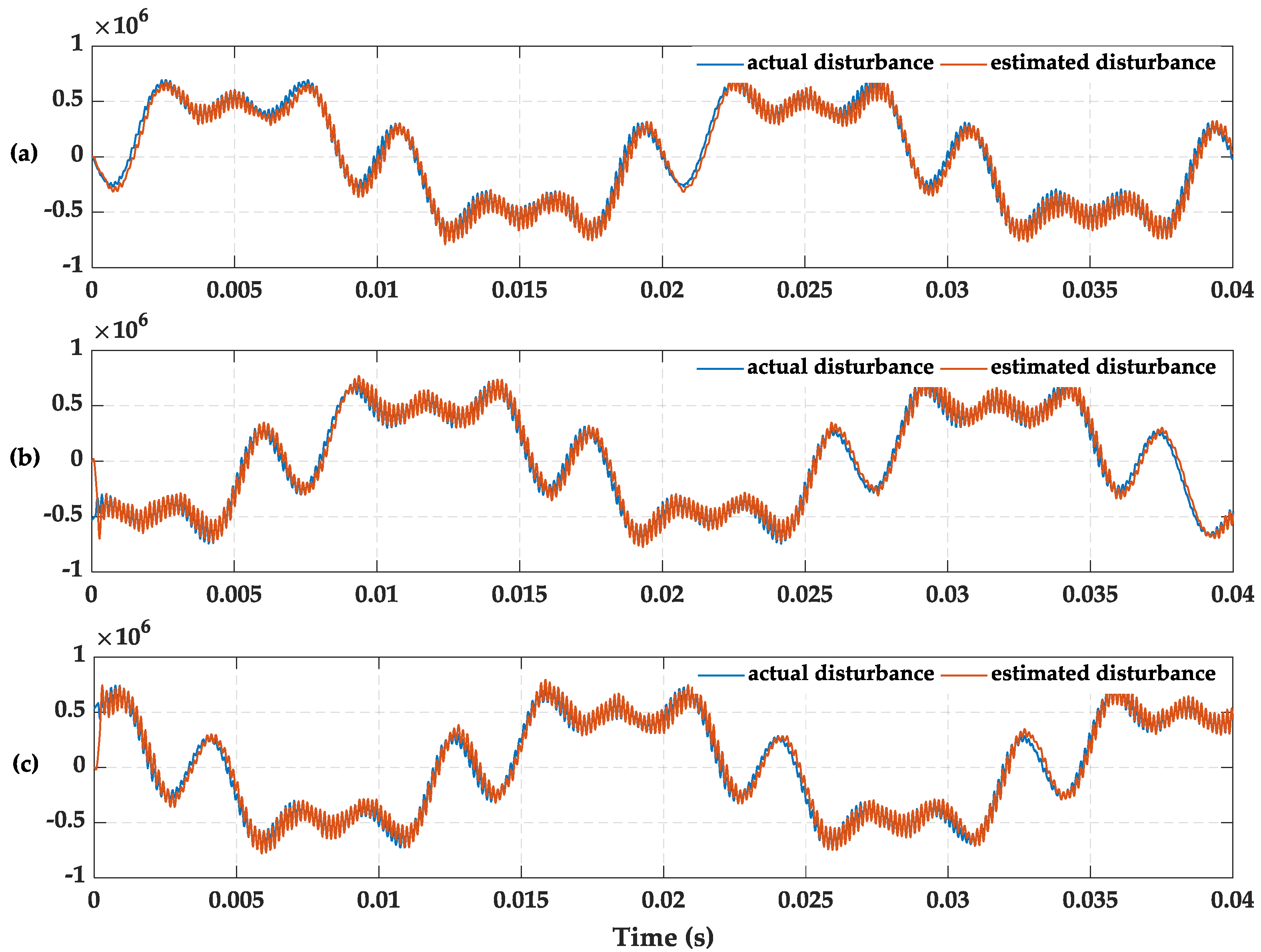
Figure 5 shows the tracing results between the actual disturbances and estimated disturbances. The controller enters the steady state after 1 ms. The estimated value has a certain lag with respect to the actual value, because the estimated output value is filtered by LPF. The cut-off frequency design needs consideration of delay and tracking curve smoothness. It is set to 2000 Hz in this paper. It is clearly shown that two waveforms well coincide with each other, which proves the validity of the proposed DOB.
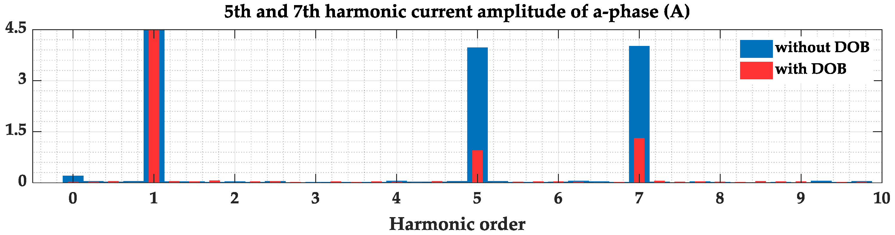
The comparison of 5th and 7th harmonic current amplitude of a-phase between original controller and proposed controller is given in Figure 6. The further comparisons of grid current harmonics and THD are listed in Table 3. The 5th harmonic current amplitude of a-phase drops from 3.99 A to 0.95 A, and the 7th harmonic current amplitude of a-phase drops from 4.04 A to 1.30 A. It is similar to the other two phases. With the sharp reduction of harmonic current, the THD of 3-phase current also drops from 6.97%, 6.75% and 6.68% to 2.86%, 2.76% and 2.97% respectively.
4.2. Simulations Under 3-Phase Voltage Unbalance Condition
A-phase line-to-ground fault is applied in this condition. The AC active current reference is 100 A, and the reactive current reference is 0 A. Figure 7a shows the unbalanced voltage. The a-phase voltage drops to 0 V. Figure 7b shows the gird current without DOB. The a-phase current not only increases by approximately 10 A, but also brings current ripples to the 3-phase current. Figure 7c shows the improved grid current using DOB. It is clearly shown that the a-phase current amplitude is restored to the normal value and the harmonics of 3-phase current are all decreased.
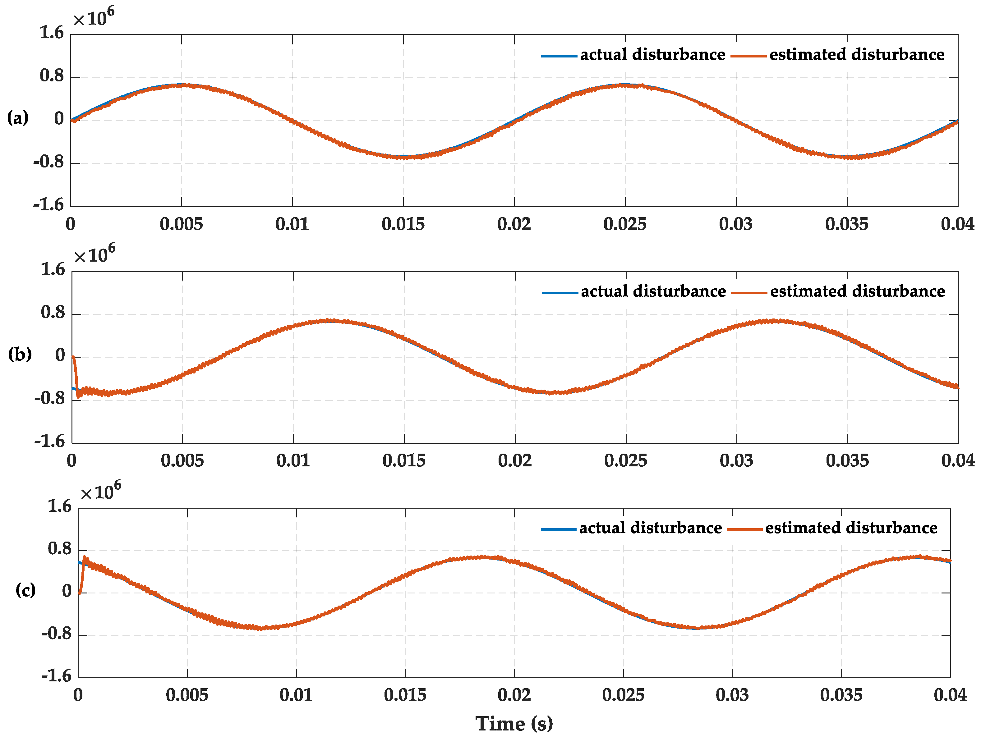
Figure 8 shows the estimation performances of unbalanced voltage disturbances using the proposed DOB. In this case, the tracking results to the actual disturbances are more efficient because the disturbances are gentler than under the harmonic condition. Thus, the inhibiting effect is better.
Table 4 represents the fundamental amplitude and THD of 3-phase current. The fundamental amplitude of a-phase current is up to 109 A, and the other two phases rise 2 A approximately. All of them decline to about 100 A when the proposed DOB is enabled. Similarly, the THD of 3-phase current drops from 4.98%, 3.75% and 3.85% to 2.52%, 2.20% and 2.17%, respectively.
4.3. Simulations Under Voltage Sag Condition
3-phase grid voltage sag condition is simulated in this case. The AC active current reference is 100 A, and the reactive current reference is 0 A. The magnitude of grid voltage amplitude drops to 20% at 0.01 s and returns to the normal value at 0.03 s, as shown in Figure 9a. Figure 9b represents the grid current without DOB. It is obvious that the grid current increases and inrush current is generated in the moment of 0.01 s and 0.03 s. Figure 9c illustrates the comparative simulation result for Figure 9b. The grid current amplitude returns to the normal value by applying the proposed DOB compensation scheme as in Figure 9c. But the inrush current still exists.
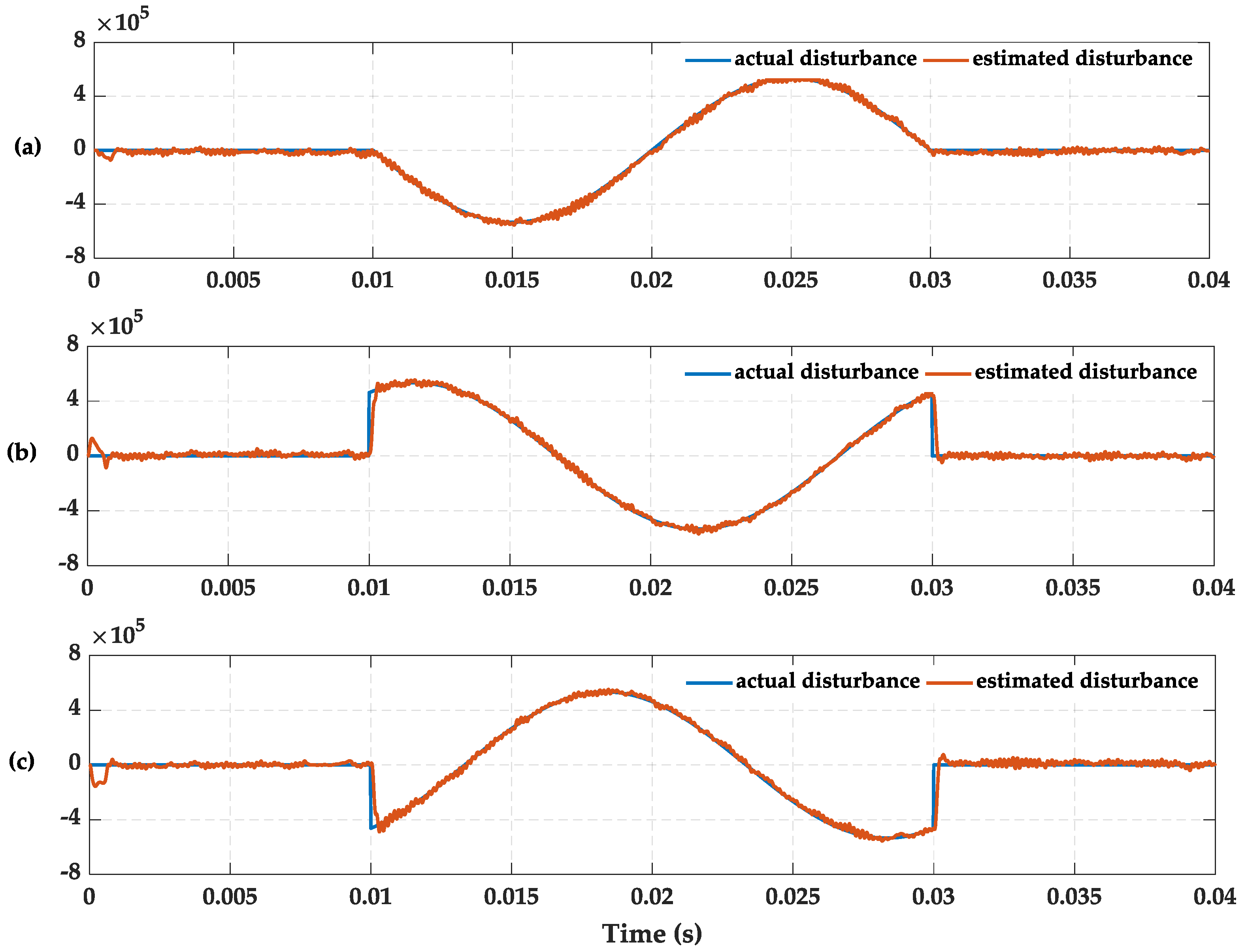
Figure 10 shows the tracking effect between actual disturbances and estimated disturbances. The estimated disturbance value fluctuates around 0 slightly when the actual disturbances are not yet injected. It proves that the proposed method doesn’t sacrifice the original control performances. The fluctuation of a-phase actual disturbance value is smooth at 0.01 s and 0.03 s. But it is not similar to b-phase and c-phase. With the rapid change of actual disturbance value, although the tracing is very fast, the difference between actual and estimated disturbance value is very large in the moment of 0.01 s and 0.03 s. It is the reason for the inrush current.
4.4. Simulations under Parameter Mismatches Condition
The inductance values are not changeless in a real system, however, the controller parameters are fixed, thus, the controller could be invalid under the inductance value varying condition. At first, a simulation of actual inductance value reduction condition is given. It proves that the proposed MPC controller with DOB can improve the control effect of grid current when the actual values of all the inductances fall by a third. Second, considering the influence of actual inductance value varying on the circulating current is much larger than that of the parameter mismatches, the compensation effect of DOB on circulating current suppression is observed by raising the inductance values by 50 times. The AC active current reference is 100 A, and the reactive current reference is 0 A.
4.4.1. Actual Inductance Value Reduction
The grid current is influenced by the actual inductance value reduction significantly as in Figure 11a. The MPC controller without DOB is affected by the parameter mismatches and there are great ripples in 3-phase current. Figure 11b represents the grid current using the MPC controller with DOB. It is shown that the proposed controller improves the performance of the original under the parameter mismatches condition.
As shown in Figure 12, the 3-phase estimated disturbance value can track the actual disturbance value stably. Furthermore, Table 5 presents the fundamental amplitude and THD of 3-phase current. It turns out that actual inductance value reduction not only brings current ripples, but also lowers the fundamental amplitude. By adding the proposed DOB on the MPC controller, the grid current amplitude returns to normal value and THD reduces significantly.
4.4.2. Actual Inductance Values Increase
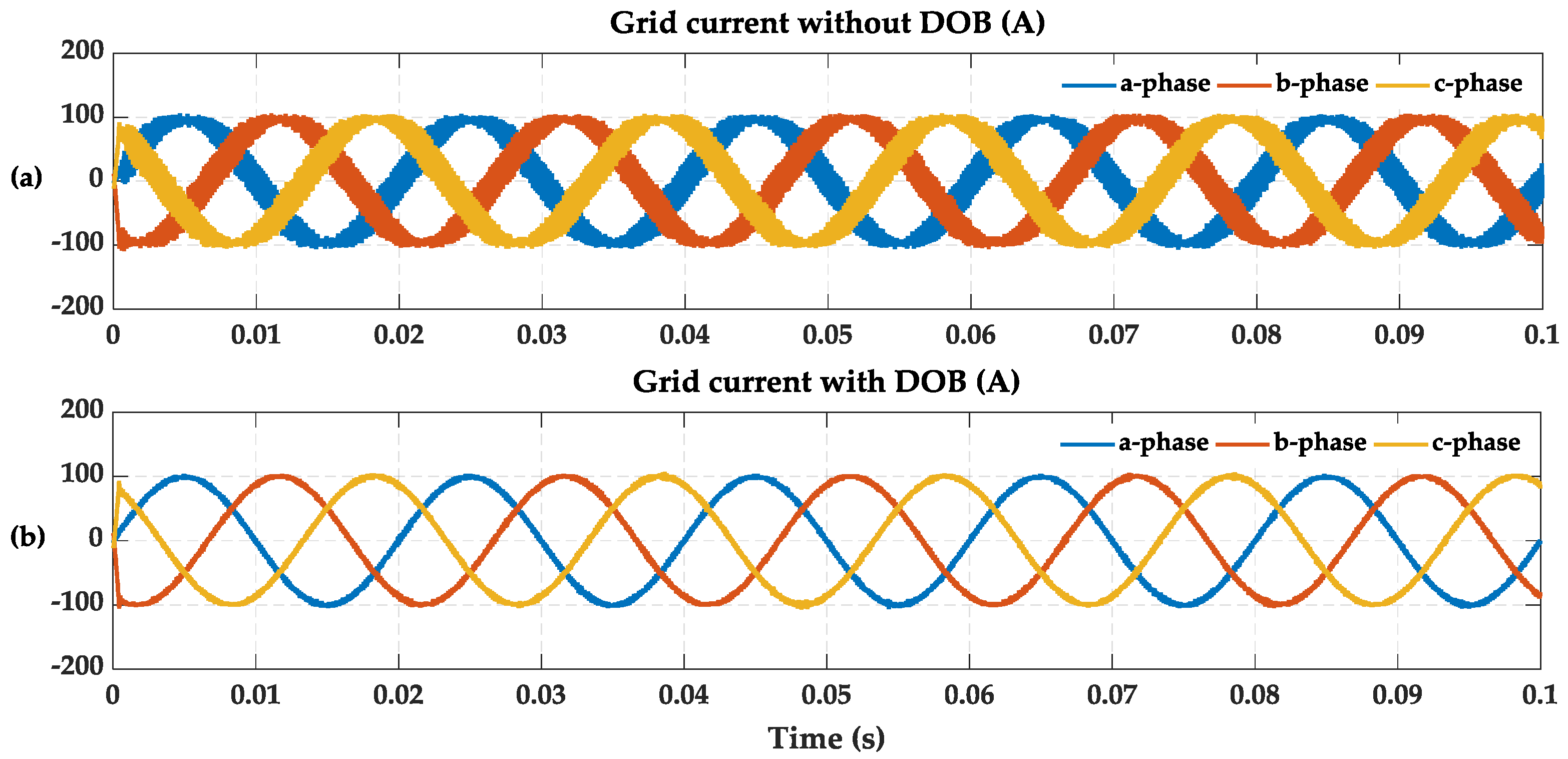
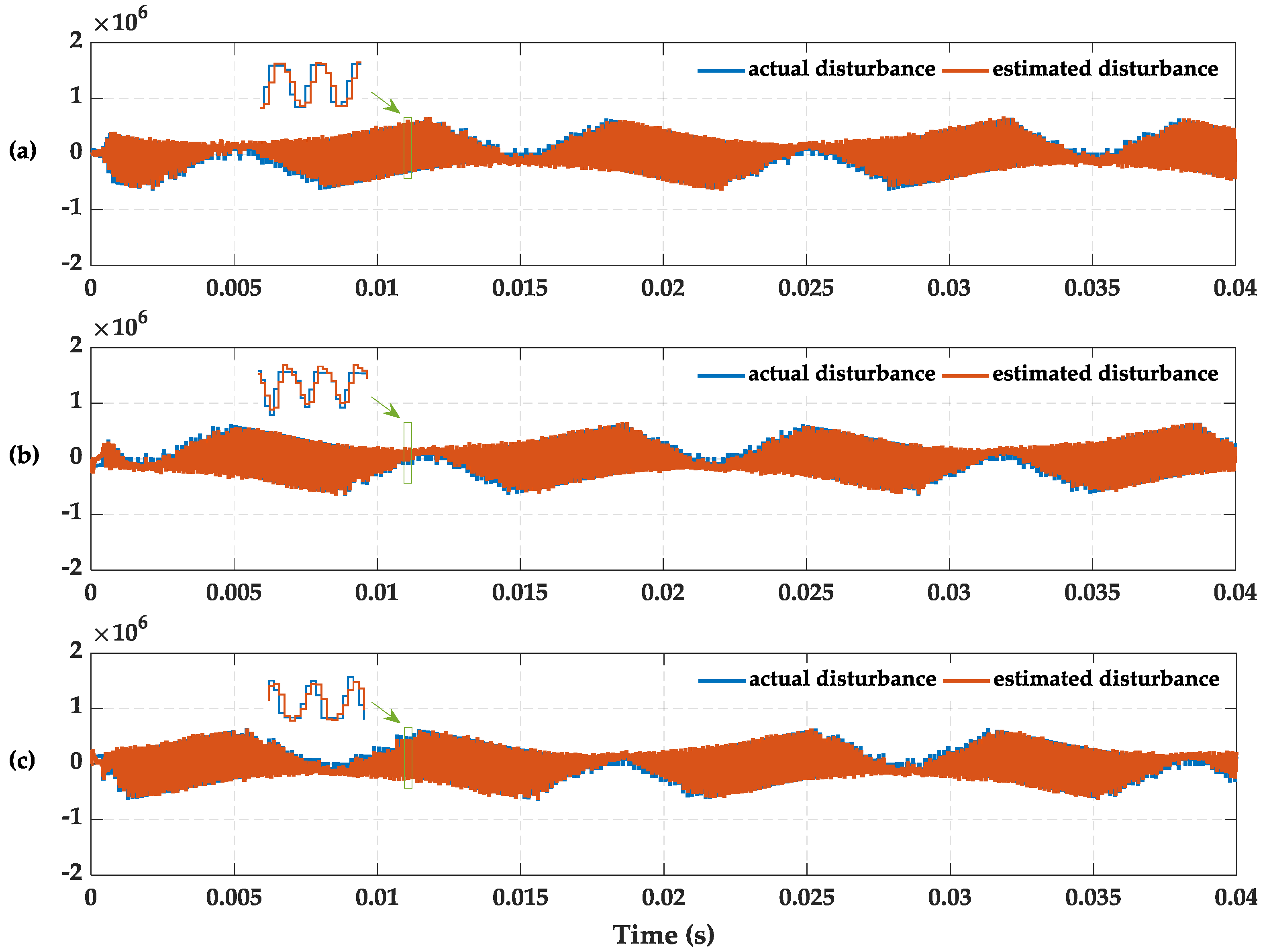
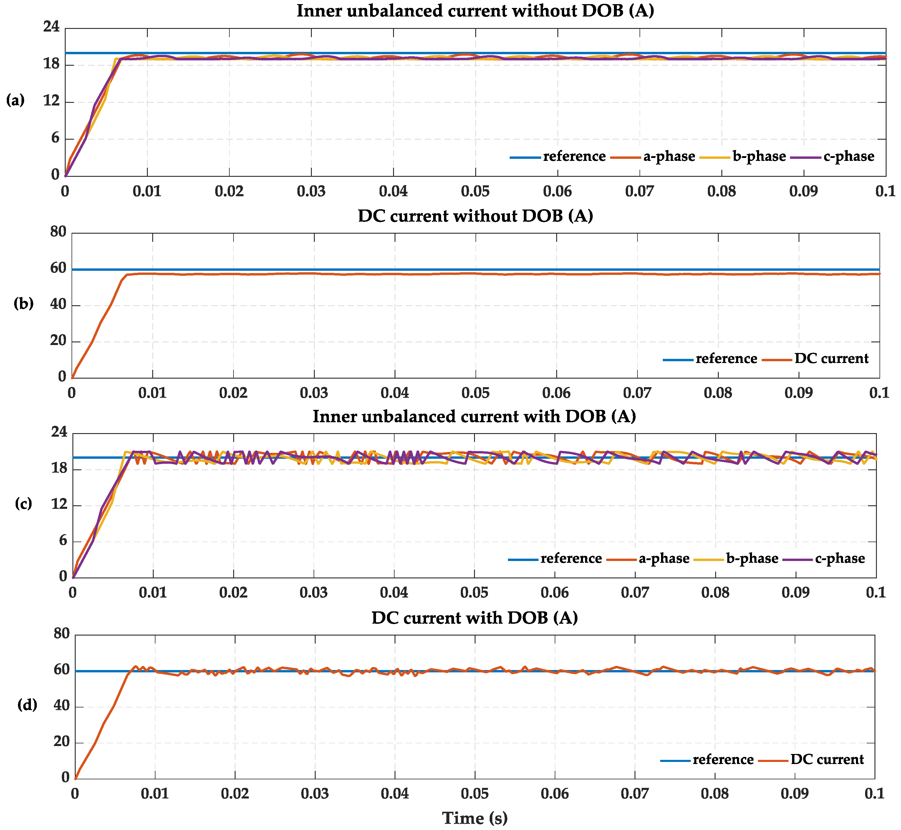
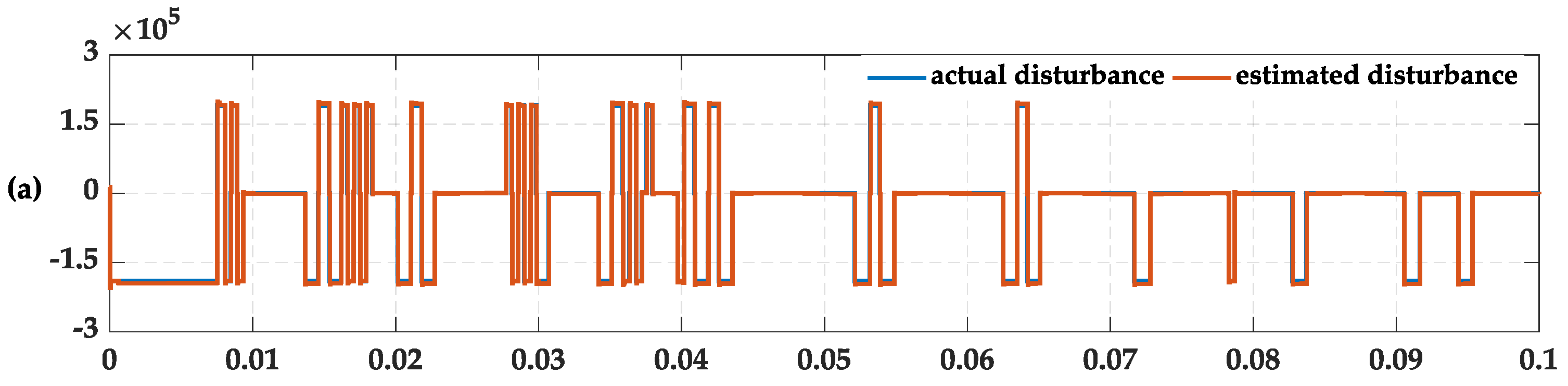
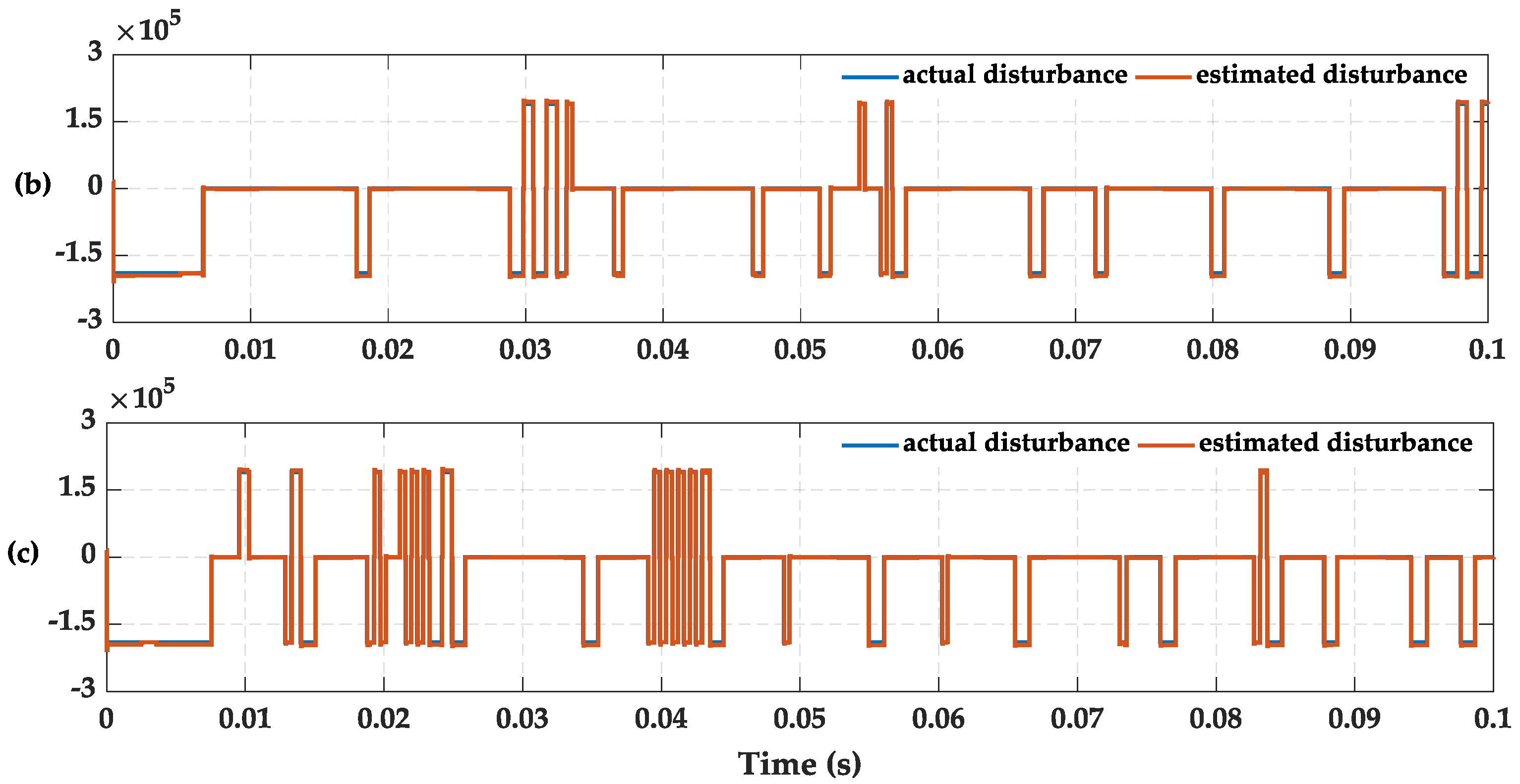
In order to verify the compensation effect of DOB on circulating current suppression, the actual inductance values are increased by 50 times. Figure 13a shows the tracking of the inner unbalanced current to its reference without DOB. Under the influence of parameter mismatches, the original controller is unable to enter a steady state, and the 3-phase inner unbalanced current which its reference is 20 A keeps fluctuating near 19 A. Shown in Figure 13b is a similar situation where the DC current that fluctuates near 57.5 A can’t trace the steady state value of 60 A because of the circulating current. Simulation results of inner unbalanced current and DC current with DOB are presented in Figure 13b,c, respectively. It is shown that the inner unbalanced current and DC current can track their references under control of the proposed method. Figure 14 shows the tracing results between actual disturbance value and estimated disturbance value. It proves that the proposed DOB can observe the change of actual system parameters and make the original MPC controller better by matching with the real system.
4.5. Power Reversal
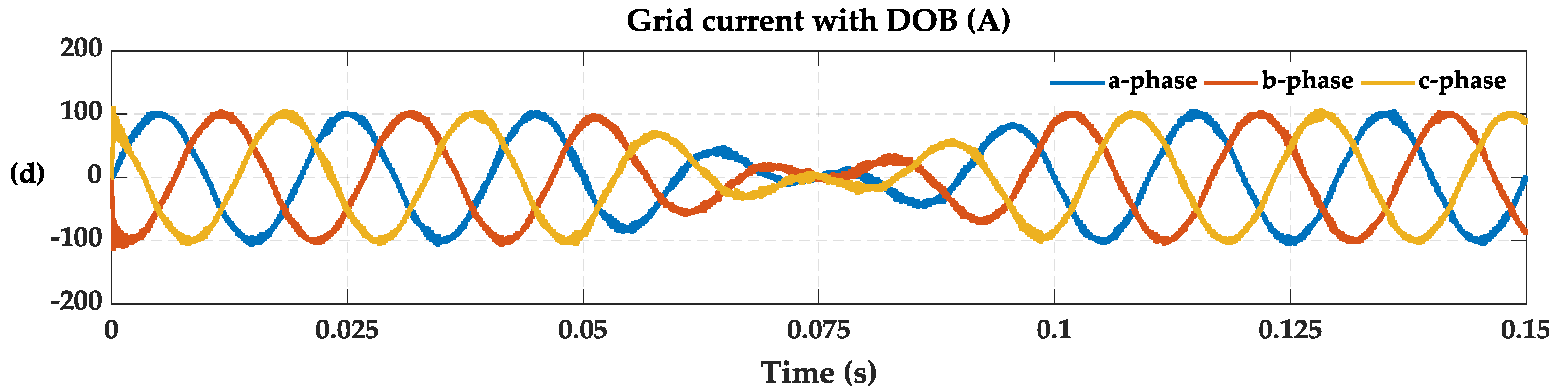
The battery energy storage system not only delivers energy to the grid through discharge, but also needs to get energy from the grid to recharge. Thus, the power reversal is simulated to verify the dynamic characteristics of the proposed control scheme. In this case, the AC reactive current reference is 0 A, the active current reference changes from 100 A to −100 A in the period of 0.05 s–0.1 s. The actual inductance values reduce by one tenth, the grid voltage contains 30% of 5th and 7th harmonics and the amplitude drops by 80%.
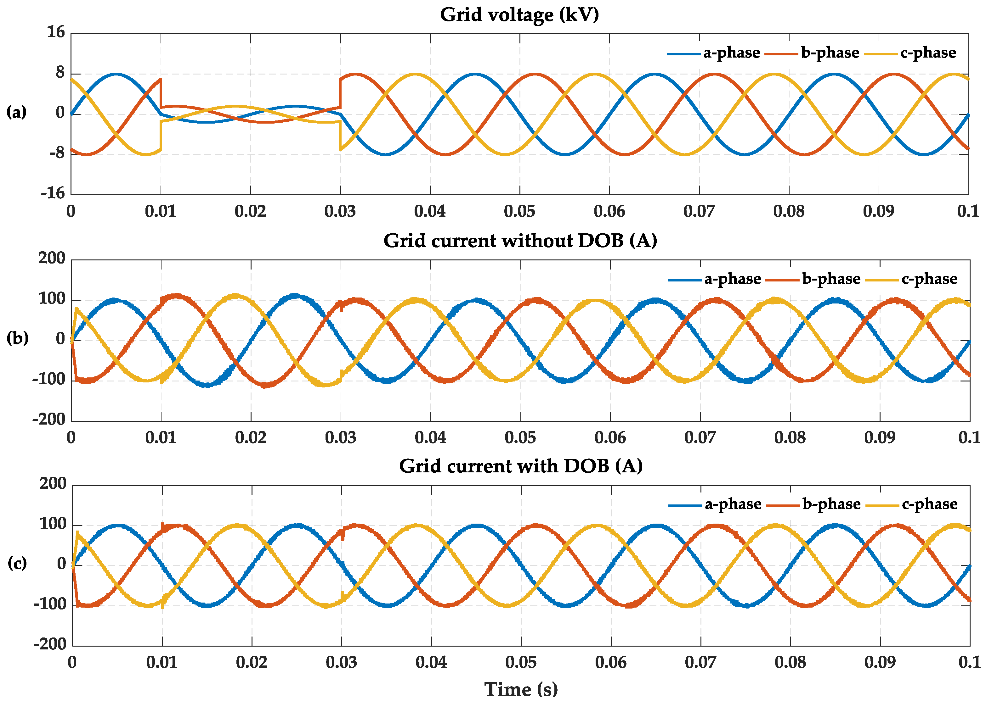
Figure 15a shows the DC current waveform. The batteries discharge before 0.075 s and the power reverses from 0.05 s to 0.1 s, then the batteries recharge until 0.15 s. Figure 15b represents the grid voltage with harmonics and sag. Aside from containing a lot of harmonics and ripples as seen in Figure 15c, the grid current is higher than its reference before 0.05 s and lower than its reference after 0.1 s. Figure 15d shows the improved current with DOB. The current keeps up with the reference stably. The tracing results of estimated disturbance value is presented in Figure 16. From these results, it is confirmed that the proposed scheme operates stably during dynamic periods.
5. Conclusions
A DOB-based MPC control scheme to restrain the disturbances caused by power quality problems and parameter mismatches is proposed. A MPC with less states and low calculation complexity is adopted and two linear discrete-time DOBs are designed. In addition, the method of parameter calculation is given. The proposed method redesigns the AC current control and circulating current control by combining with DOBs. The purpose is to enhance the anti-disturbance ability of MPC. The proposed DOB-based MPC control strategy has quite low cost of computation with the minimum order and optimal performance property.
The performances of the designed controller are simulated under five different system operations, including harmonics, 3-phase unbalance, voltage sag, parameter mismatches and power reversal. By comparing the control effect of AC current and circulating current under the original MPC controller and the MPC controller with DOB, respectively, the proposed method is validated as being effective. The AC current can maintain a low harmonic content and normal amplitude when it is disturbed by gird voltage, inductance and power. The inner unbalanced current and DC current can track the set-value stably under the inductance value increase condition. Besides, it is proved that the DOB is fast and steady by estimating the disturbances and uncertainties. However, a rigorous analysis of SM capacitor voltage balancing control is nontrivial, and further researches will be conducted to work on this interesting issue.
Author Contributions
All authors contributed collectively to the manuscript preparation and approved the final manuscript.
Funding
This research was funded by [State Grid Corporation of China science and technology project: Key technologies and equipment of DC step-up power collection and integration for large-scale PV Station].
Conflicts of Interest
The authors declare no conflict of interest.
References
- Yang, T.; Mok, K.T.; Tan, S.C.; Lee, C.K.; Hui, S.Y.R. Electric springs with coordinated battery management for reducing voltage and frequency fluctuations in microgrids. IEEE Trans. Smart Grid 2018, 9, 1943–1952. [Google Scholar] [CrossRef]
- Jiang, W.; Xue, S.; Zhang, L.; Xu, W.; Yu, K.; Chen, W.; Zhang, L. Flexible power distribution control in asymmetrical cascaded multilevel converter based hybrid energy storage system. IEEE Trans. Ind. Electron. 2018, 65, 6150–6159. [Google Scholar] [CrossRef]
- Yang, P.; Xia, Y.; Yu, M.; Wei, W.; Peng, Y. A decentralized coordination control method for parallel bidirectional power converters in a hybrid AC/DC microgrid. IEEE Trans. Ind. Electron. 2018, 65, 6217–6228. [Google Scholar] [CrossRef]
- Kwon, O.; Kim, J.S.; Kwon, J.M.; Kwon, B.H. Bidirectional grid-connected single-power-conversion converter with low input battery voltage. IEEE Trans. Ind. Electron. 2018, 65, 3136–3144. [Google Scholar] [CrossRef]
- Mehrasa, M.; Pouresmaeil, E.; Zabihi, S.; Vechiu, I.; Catalão, J.P.S. A multi-loop control technique for the stable operation of modular multilevel converters in HVDC transmission systems. Electr. Power Energy Syst. 2018, 96, 194–207. [Google Scholar] [CrossRef]
- Lee, K.J.; Park, B.G.; Kim, R.Y.; Hyun, D.S. Robust predictive current controller based on a disturbance estimator in a three-phase grid-connected inverter. IEEE Trans. Power Electron. 2012, 27, 276–283. [Google Scholar] [CrossRef]
- Xia, C.; Wang, M.; Song, Z.; Liu, T. Robust model predictive current control of three-phase voltage source PWM rectifier with online disturbance observation. IEEE Trans. Ind. Inform. 2012, 8, 459–471. [Google Scholar] [CrossRef]
- Mehrasa, M.; Pouresmaeil, E.; Akorede, M.F.; Zabihi, S.; Catalão, J.P.S. Function-based modulation control for modular multilevel converters under varying loading and parameters conditions. IET Gener. Trans. Distrib. 2017, 11, 3222–3230. [Google Scholar] [CrossRef]
- Hagiwara, M.; Akagi, H. Experiment and simulation of a modular push–pull PWM converter for a battery energy storage system. IEEE Trans. Ind. Appl. 2014, 50, 1131–1140. [Google Scholar] [CrossRef]
- Maharjan, L.; Yamagishi, T.; Akagi, H. Active-power control of individual converter cells for a battery energy storage system based on a multilevel cascade PWM converter. IEEE Trans. Power Electron. 2012, 27, 1099–1107. [Google Scholar] [CrossRef]
- Song, J.; Zhang, W.; Liang, H.; Jiang, J.; Yu, W. Fault-tolerant control for a flexible group battery energy storage system based on cascaded multilevel converters. Energies 2018, 11, 171. [Google Scholar] [CrossRef]
- Liang, H.; Guo, L.; Song, J.; Yang, Y.; Zhang, W.; Qi, H. State-of-charge balancing control of a modular multilevel converter with an integrated battery energy storage. Energies 2018, 11, 873. [Google Scholar] [CrossRef]
- Ota, J.I.Y.; Sato, T.; Akagi, H. Enhancement of performance, availability, and flexibility of a battery energy storage system based on a modular multilevel cascaded converter (MMCC-SSBC). IEEE Trans. Power Electron. 2016, 31, 2791–2799. [Google Scholar] [CrossRef]
- Zhang, M.; Huang, L.; Yao, W.; Lu, Z. Circulating harmonic current elimination of a CPS-PWM-based modular multilevel converter with a plug-in repetitive controller. IEEE Trans. Power Electron. 2014, 29, 2083–2097. [Google Scholar] [CrossRef]
- Yang, L.; Li, Y.; Li, Z.; Wang, P.; Xu, S.; Gou, R. Loss optimization of MMC by second-order harmonic circulating current injection. IEEE Trans. Power Electron. 2018, 33, 5739–5753. [Google Scholar] [CrossRef]
- Mehrasa, M.; Pouresmaeil, E.; Zabihi, S.; Catalao, J.P. Dynamic model, control and stability analysis of MMC in HVDC transmission systems. IEEE Trans. Power Deliv. 2017, 32, 1471–1482. [Google Scholar] [CrossRef]
- Mehrasa, M.; Pouresmaeil, E.; Taheri, S.; Vechiu, I.; Catalão, J.P. Novel control strategy for modular multilevel converters based on differential flatness theory. IEEE J. Emerg. Sel. Top. Power Electron. 2017, 6, 888–897. [Google Scholar] [CrossRef]
- Mehrasa, M.; Pouresmaeil, E.; Zabihi, S.; Caballero, J.T.; Catalão, J. A novel modulation function-based control of modular multilevel converters for high voltage direct current transmission systems. Energies 2016, 9, 867. [Google Scholar] [CrossRef]
- Qin, J.; Saeedifard, M. Predictive control of a modular multilevel converter for a back-to-back HVDC system. IEEE Trans. Power Deliv. 2012, 27, 1538–1547. [Google Scholar]
- Yang, J.; Li, S.; Chen, X.; Li, Q. Disturbance rejection of dead-time processes using disturbance observer and model predictive control. Chem. Eng. Res. Des. 2011, 89, 125–135. [Google Scholar] [CrossRef]
- Qin, S.J.; Badgwell, T.A. A survey of industrial model predictive control technology. Control Eng. Pract. 2003, 11, 733–764. [Google Scholar] [CrossRef] [Green Version]
- Liao, K.; Xu, Y. A robust load frequency control scheme for power systems based on second-order sliding mode and extended disturbance observer. IEEE Trans. Ind. Inform. 2018, 14, 3076–3086. [Google Scholar] [CrossRef]
- Wang, C.; Mi, Y.; Fu, Y.; Wang, P. Frequency control of an isolated micro-grid using double sliding mode controllers and disturbance observer. IEEE Trans. Smart Grid 2018, 9, 923–930. [Google Scholar] [CrossRef]
- Wang, B.; Dong, Z.; Yu, Y.; Wang, G.; Xu, D. Static-errorless deadbeat predictive current control using second-order sliding-mode disturbance observer for induction machine drives. IEEE Trans. Power Electron. 2018, 33, 2395–2403. [Google Scholar] [CrossRef]
- Yang, J.; Cui, H.; Li, S.; Zolotas, A. Optimized active disturbance rejection control for DC-DC buck converters with uncertainties using a reduced-order GPI observer. IEEE Trans. Circuits Syst. 2018, 65, 832–841. [Google Scholar] [CrossRef]
- Back, J.; Shim, H. Adding robustness to nominal output-feedback controllers for uncertain nonlinear systems: a nonlinear version of disturbance observer. Automatica 2008, 44, 2528–2537. [Google Scholar] [CrossRef]
- Liu, H.; Li, S. Speed control for PMSM servo system using predictive functional control and extended state observer. IEEE Trans. Ind. Electron. 2011, 59, 1171–1183. [Google Scholar] [CrossRef]
- Barros, J.D.; Silva, J.F.A.; Élvio, G.A.J. Fast-predictive optimal control of NPC multilevel converters. IEEE Trans. Ind. Electron. 2012, 60, 619–627. [Google Scholar] [CrossRef]
- Nguyen, H.T.; Jung, J.W. Disturbance-rejection-based model predictive control: flexible-mode design with a modulator for three-phase inverters. IEEE Trans. Ind. Electron. 2018, 65, 2893–2903. [Google Scholar] [CrossRef]
- Moon, J.W.; Gwon, J.S.; Park, J.W.; Kang, D.W.; Kim, J.M. Model predictive control with a reduced number of considered states in a modular multilevel converter for HVDC system. IEEE Trans. Power Deliv. 2015, 30, 608–617. [Google Scholar] [CrossRef]
- Tu, Q.; Xu, Z.; Xu, L. Reduced switching-frequency modulation and circulating current suppression for modular multilevel converters. IEEE Trans. Power Deliv. 2011, 26, 2009–2017. [Google Scholar]
- Moon, J.W.; Kim, C.S.; Park, J.W.; Kang, D.W.; Kim, J.M. Circulating current control in MMC under the unbalanced voltage. IEEE Trans. Power Deliv. 2013, 28, 1952–1959. [Google Scholar] [CrossRef]
- Kim, K.S.; Rew, K.H. Reduced order disturbance observer for discrete-time linear systems. Automatica 2013, 49, 968–975. [Google Scholar] [CrossRef]
Figure 1.
Circuit diagram of three-phase MMC.

Figure 2.
Model of single-phase of the three-phase MMC.

Figure 3.
System structure of simulation.

Figure 4.
Simulations under harmonic grid voltage condition: (a) Harmonic distorted grid voltage; (b) Grid current without DOB; (c) Grid current with DOB.
Figure 4.
Simulations under harmonic grid voltage condition: (a) Harmonic distorted grid voltage; (b) Grid current without DOB; (c) Grid current with DOB.

Figure 5.
Actual disturbance value and estimated disturbance value under harmonic condition: (a) A-phase; (b) B-phase; (c) C-phase.
Figure 5.
Actual disturbance value and estimated disturbance value under harmonic condition: (a) A-phase; (b) B-phase; (c) C-phase.

Figure 6.
Comparison of 5th and 7th harmonic current amplitude of a-phase between grid current without DOB and with DOB.
Figure 6.
Comparison of 5th and 7th harmonic current amplitude of a-phase between grid current without DOB and with DOB.

Figure 7.
Simulations under unbalanced voltage condition: (a) Unbalanced grid voltage; (b) Grid current without DOB; (c) Grid current with DOB.
Figure 7.
Simulations under unbalanced voltage condition: (a) Unbalanced grid voltage; (b) Grid current without DOB; (c) Grid current with DOB.

Figure 8.
Actual disturbance value and estimated disturbance value under unbalanced voltage condition: (a) A-phase; (b) B-phase; (c) C-phase.
Figure 8.
Actual disturbance value and estimated disturbance value under unbalanced voltage condition: (a) A-phase; (b) B-phase; (c) C-phase.

Figure 9.
Simulations under voltage sag condition: (a) Grid voltage; (b) Grid current without DOB; (c) Grid current with DOB.
Figure 9.
Simulations under voltage sag condition: (a) Grid voltage; (b) Grid current without DOB; (c) Grid current with DOB.

Figure 10.
Actual disturbance value and estimated disturbance value under voltage sag condition: (a) A-phase; (b) B-phase; (c) C-phase.
Figure 10.
Actual disturbance value and estimated disturbance value under voltage sag condition: (a) A-phase; (b) B-phase; (c) C-phase.

Figure 11.
Simulations under actual inductance value reduction condition: (a) Grid current without DOB; (b) Grid current with DOB.
Figure 11.
Simulations under actual inductance value reduction condition: (a) Grid current without DOB; (b) Grid current with DOB.

Figure 12.
Actual disturbance value and estimated disturbance value under actual inductance value reduction condition: (a) A-phase; (b) B-phase; (c) C-phase.
Figure 12.
Actual disturbance value and estimated disturbance value under actual inductance value reduction condition: (a) A-phase; (b) B-phase; (c) C-phase.

Figure 13.
Simulations under actual inductance value increase condition: (a) Tracking of the inner unbalanced current to its reference without DOB; (b) Tracking of the DC current to its reference without DOB; (c) Tracking of the inner unbalanced current to its reference with DOB; (d) Tracking of the DC current to its reference with DOB.

Figure 14.
Actual disturbance value and estimated disturbance value under actual inductance value increase condition: (a) A-phase; (b) B-phase; (c) C-phase.
Figure 14.
Actual disturbance value and estimated disturbance value under actual inductance value increase condition: (a) A-phase; (b) B-phase; (c) C-phase.


Figure 15.
Simulations under power reversal condition: (a) DC current; (b) Grid voltage; (c) Grid current without DOB; (d) Grid current with DOB.
Figure 15.
Simulations under power reversal condition: (a) DC current; (b) Grid voltage; (c) Grid current without DOB; (d) Grid current with DOB.


Figure 16.
Actual disturbance value and estimated disturbance value under power reversal condition: (a) A-phase; (b) B-phase; (c) C-phase.
Figure 16.
Actual disturbance value and estimated disturbance value under power reversal condition: (a) A-phase; (b) B-phase; (c) C-phase.


Table 1.
Main circuit parameters.
| Parameters | Values | Units |
|---|---|---|
| Rated Power | 1.2 | MW |
| AC System Voltage | 9800 | V |
| Line Frequency | 50 | Hz |
| AC System Inductance | 2 | mH |
| DC Bus Voltage | 20 | kV |
| Number of SMs per arm | 10 | - |
| SM Capacitance | 0.002 | F |
| SM Capacitor Voltage | 2000 | V |
| Arm Inductance | 0.02 | H |
| Sampling and control period | 20 | μs |
Table 2.
Control parameters of DOB 1 and DOB 2.
| Parameters | DOB 1 | DOB 2 |
|---|---|---|
| Φ | 1 | 1 |
| Γ | 0.0017 | 0.0005 |
| G | 0.00002 | 0.00001 |
| C | 1 | 1 |
| K | 40,000 | 100,000 |
| λ | 0.2 | 1 |
Table 3.
Comparisons of grid current under harmonic grid voltage condition.
| Phase | 5th/7th Harmonic (A) | THD (%) | ||
|---|---|---|---|---|
| Without DOB | With DOB | Without DOB | With DOB | |
| A | 3.99/4.04 | 0.95/1.30 | 6.97 | 2.86 |
| B | 4.02/4.01 | 0.90/1.31 | 6.75 | 2.76 |
| C | 4.03/4.01 | 0.97/1.31 | 6.68 | 2.97 |
Table 4.
Comparisons of grid current under unbalanced grid voltage condition.
| Phase | Fundamental Amplitude (A) | THD (%) | ||
|---|---|---|---|---|
| Without DOB | With DOB | Without DOB | With DOB | |
| A | 109 | 99.97 | 4.98 | 2.52 |
| B | 102.1 | 100.2 | 3.75 | 2.20 |
| C | 101.9 | 99.79 | 3.85 | 2.17 |
Table 5.
Comparisons of grid current under actual inductance value reduction condition.
| Phase | Fundamental Amplitude (A) | THD (%) | ||
|---|---|---|---|---|
| Without DOB | With DOB | Without DOB | With DOB | |
| A | 95.66 | 100 | 21.56 | 2.12 |
| B | 95.68 | 99.96 | 21.44 | 2.06 |
| C | 95.62 | 100 | 21.56 | 2.13 |
© 2018 by the authors. Licensee MDPI, Basel, Switzerland. This article is an open access article distributed under the terms and conditions of the Creative Commons Attribution (CC BY) license (http://creativecommons.org/licenses/by/4.0/).
Share and Cite
MDPI and ACS Style
Liao, Y.; You, J.; Yang, J.; Wang, Z.; Jin, L. Disturbance-Observer-Based Model Predictive Control for Battery Energy Storage System Modular Multilevel Converters. Energies 2018, 11, 2285. https://doi.org/10.3390/en11092285
AMA Style
Liao Y, You J, Yang J, Wang Z, Jin L. Disturbance-Observer-Based Model Predictive Control for Battery Energy Storage System Modular Multilevel Converters. Energies. 2018; 11(9):2285. https://doi.org/10.3390/en11092285
Chicago/Turabian StyleLiao, Yantao, Jun You, Jun Yang, Zuo Wang, and Long Jin. 2018. "Disturbance-Observer-Based Model Predictive Control for Battery Energy Storage System Modular Multilevel Converters" Energies 11, no. 9: 2285. https://doi.org/10.3390/en11092285
Note that from the first issue of 2016, this journal uses article numbers instead of page numbers. See further details here.