Parameter Identification of Inverter-Fed Induction Motors: A Review


1
School of Electrical Engineering, Beijing Jiaotong University, Beijing 100044, China
2
Department of Energy Technology, Aalborg University, 9220 Aalborg, Denmark
3
Beijing Engineering Research Center for Electrical Rail Transit, Beijing 100044, China
*
Author to whom correspondence should be addressed.
Energies 2018, 11(9), 2194; https://doi.org/10.3390/en11092194
Submission received: 30 July 2018
/
Revised: 17 August 2018
/
Accepted: 19 August 2018
/
Published: 22 August 2018
(This article belongs to the Special Issue 10 Years Energies - Horizon 2028)
Abstract
:Induction motor parameters are essential for high-performance control. However, motor parameters vary because of winding temperature rise, skin effect, and flux saturation. Mismatched parameters will consequently lead to motor performance degradation. To provide accurate motor parameters, in this paper, a comprehensive review of offline and online identification methods is presented. In the implementation of offline identification, either a DC voltage or single-phase AC voltage signal is injected to keep the induction motor standstill, and the corresponding identification algorithms are discussed in the paper. Moreover, the online parameter identification methods are illustrated, including the recursive least square, model reference adaptive system, DC and high-frequency AC voltage injection, and observer-based techniques, etc. Simulations on selected identification techniques applied to an example induction motor are presented to demonstrate their performance and exemplify the parameter identification methods.
1. Introduction
Induction motors (IMs) are widely used in practical industrial applications due to the low cost, high robustness, and high reliability [1]. To achieve high control performance, various control methods like field orientation control (FOC) [2], direct torque control (DTC) [3,4], and model predictive control (MPC) [5,6] are developed for industrial IMs. Among the motor control strategies, the indirect field orientation control (IFOC) [7] is dominated due to its superior dynamic performance and easy implementation; while for the FOC, the decoupling between the torque and the flux is introduced, enabling the IM operating as a DC motor. Notably, no matter which method is used, the drive performance highly depends on motor parameters. For instance, in the IFOC method, the rotor flux position is calculated by adding the measured rotor angular frequency from a speed sensor and the computed slip angular frequency from the torque command. Accordingly, the rotor flux orientation of the IFOC heavily depends on the slip frequency, which is relative to the rotor resistance and rotor inductance. Meanwhile, the d-axis current reference is supplied to the current regulator in the dq-reference frame, and the reference current is calculated considering the ratio of flux and magnetizing inductance. Moreover, the stator resistance is essential for the flux estimation, especially in low-frequency applications. As a consequence, the parameter deviation degrades the control performance. The degradation is reflected in two ways: the inaccurate current reference calculation for the control loops and the improper slip frequency computation for the rotor flux orientation. In all, mismatched parameters have negative influence on the motor drive performance. In addition, the accurate parameter identification of motors is also beneficial to the sensor-less speed control [8,9], motor temperature monitoring (health status monitoring) [10,11,12], and fault diagnosis [13,14].
In general, typical parameters that are used in the control of motors include the stator resistance Rs, stator leakage inductance Lls, magnetizing inductance Lm, rotor resistance Rr, and rotor leakage inductance Llr. In practical cases, an inverter is provided by a manufacturer, while the motor is from another manufacturer. Therefore, parameters are unknown when the motor is fed by the inverter that is not from the same manufacturer. Hence, the offline identification should be developed to obtain these parameters. The identified parameters can not only ensure a successful start-up of the motor but also offer the initialization for online identification. According to the voltage supplied to the motor, offline parameter identification techniques can be grouped into two categories: DC-voltage-injected and single-phase-AC-injected strategies. The methods based on injecting a DC voltage usually focus on the steady-state equivalence of the motor in such a way that the stator resistance is calculated or estimated [15], and the transient current response is then analyzed to determine the rotor resistance or the magnetizing inductance [16,17,18]. Notably, in this case, the delays induced by the inverter nonlinearity and control [19,20,21] should be compensated for an accurate voltage reconstruction. Similarly, the methods by injecting single-phase-AC-signals [22,23,24,25] also result in an equivalent circuit to calculate the parameters. Further offline identification algorithms have been presented in the literature; e.g., the recursive least square method in [26]. Compared with DC-voltage-injected methods, these methods can provide more information of the parameters.
During the motor operation, effects of the temperature rise, skin effect, and flux saturation will inevitably drift the parameters. The heat induced by motor power losses leads to the motor temperature change and thereby affecting the stator and rotor resistance. Furthermore, the rotor frequency and temperature in respect to the skin effect will contribute to the rotor resistance variations. Finally, the magnetizing flux level may cause saturation, which in turn affects the magnetizing inductance. As a consequence, motor parameters are deviated from their nominal values in operation. To ensure the performance of the IM systems, online parameter identification is necessary to provide real-time parameters. Among all the necessary motor parameters, only certain of them have a significant impact on the overall control performance during operation. Thus, the online identification usually aims at one or several parameters. Many efforts have been made to the online parameter identification. For instance, in [27,28,29], the recursive least square technique was presented, where the over-parameter problem was discussed and solved by using an improved model with a predetermined stator resistance. In [30,31,32,33,34,35,36,37], a model reference adaptive system (MRAS) based method was introduced, and in this case, the rotor resistance or the rotor time constant is estimated, particularly, for the sensor-less speed control systems. Additionally, in [38,39], a DC signal was injected to the motor to estimate the stator resistance, and subsequently the stator temperature. Alternatively, in [40,41,42], a high frequency AC signal was added to the d-axis current reference (i.e., an AC signal is injected) to estimate the motor parameters. In addition, online estimation algorithms based on the extend Luenberger observer, sliding mode observer, and Kalman filter were investigated in [43,44,45,46,47,48,49,50,51,52,53,54]. More methods of artificial neural network (ANN) and genetic algorithm (GA) were explored in [55,56,57,58,59,60,61,62].
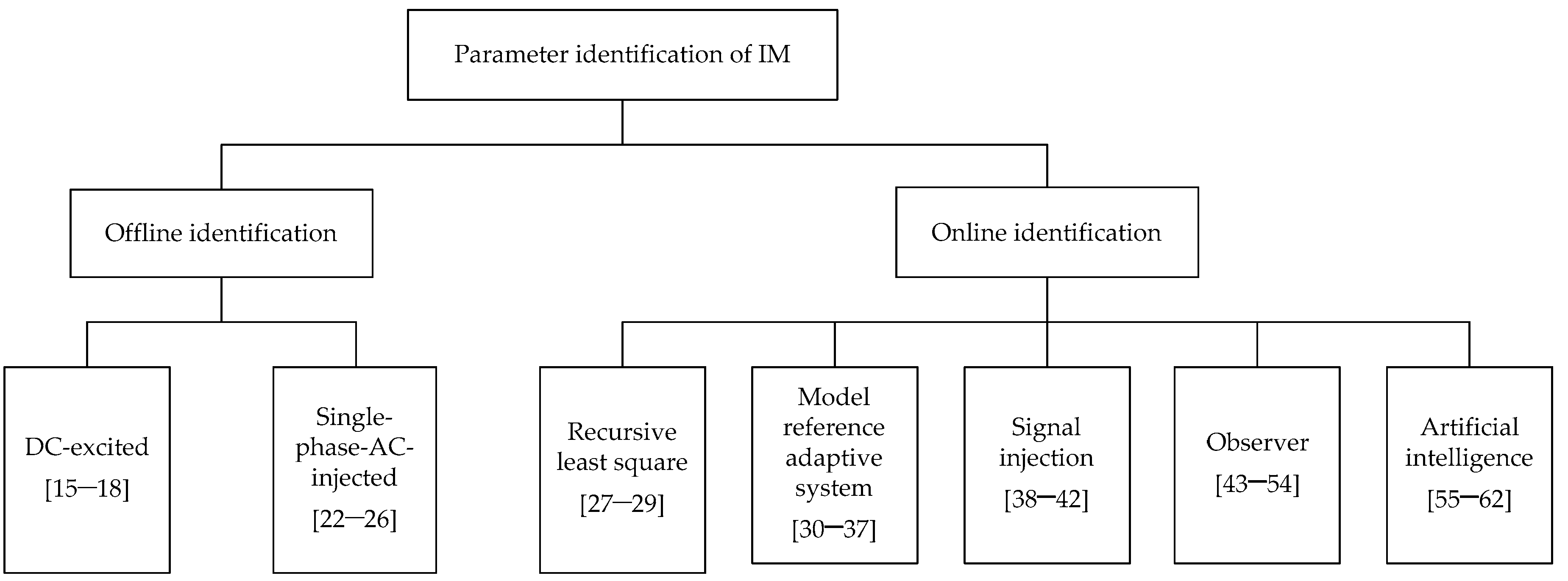
With the discussion and consideration, the aim of this paper is to provide a detailed and comprehensive review of the offline and online parameter identification methods for IM systems. These illustrated methods are categorized as shown in Figure 1, where key references of those methods can be found. The rest of this paper is organized as follows: Section 2 summarizes the offline methods for motor parameter identification. Section 3 overviews the online parameter estimation techniques for IMs. Simulation results of selected parameter identification methods are provided in Section 4 in order to benchmark their performance. The paper is concluded in Section 5 with further remarks on parameter identification in motor drive applications.
2. Offline Parameter Identification
In general, the standard no-load and blocked-rotor tests are applied to an IM to measure its parameters. However, the motor is usually installed and connected with an inverter, and thus the rotor of the IM is coupled to the loads. Therefore, an offline identification procedure is usually performed before the motor is started up. This procedure is also called self-commissioning. One of the two most-commonly used offline identification methods is to inject a DC voltage to the motor. Another one is to inject a single-phase AC voltage to the motor instead of performing the traditional blocked-rotor test, where the motor keeps standstill, since the rotating magnetic field cannot be established without taking special measures.
2.1. DC-Excited Methods
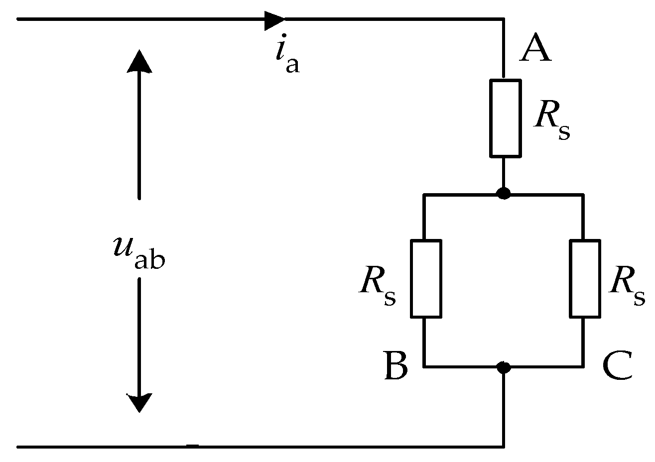
In the DC-excited test, the pulse width-modulation (PWM) is applied to the phase-A bridge of the inverter, and lower switches of the phase-B and phase-C are turned on. Thus, an average DC voltage is injected to the motor. After the motor current comes to the steady state, the equivalent circuit can be obtained, as it is shown in Figure 2. Accordingly, the stator resistance Rs can be calculated by measuring the relative DC current through a current sensor. Meanwhile, the DC-link voltage of the inverter is considerably high, while the output voltage of the inverter is very low, resulting in a small duty cycle of the PWM signal. In this case, the inverter non-linearity [19,20,21] related to the dead-time, turn-on and turn-off delays, and the drop voltage becomes significant. To solve this issue, the output voltage error compensation is required. On the other hand, the ratio between the current difference and voltage difference can be obtained, and thus, the resistance is attained, after two DC-excited voltages are supplied to the motor [15].
Furthermore, other methods based on the transient voltage or current responses are also developed to obtain more parameters in addition to the stator resistance after the DC-excited test. For instance, in [16,17], a high frequency disturbance and a step reversal voltage were injected, respectively, to identify parameters by means of a first-order recursive least square estimator. In [18], the stator resistance Rs, rotor resistance Rr, and magnetizing inductance Lm are measured using the observed discharging waveform, after the power devices of the inverter are switched off. Nevertheless, the DC signal injection method (i.e., the DC-excited methods) is dedicated to identify the stator resistance. When more parameters should be identified, additional methods should be associated with the DC-excited test.
2.2. Single-Phase-AC-Injected Methods
In the single-phase-AC-injected test, the voltage phase difference between the phase-A and phase-B is 180°, while the PWM signal for the phase-C is the same as that for the phase-B. Therefore, a single-phase AC voltage is equivalently applied to the motor, and the phase-B and phase-C are shorted. Hence, as the motor is kept at a standstill (i.e., the rotating speed ωr = 0), the following assumptions should be reasonable:
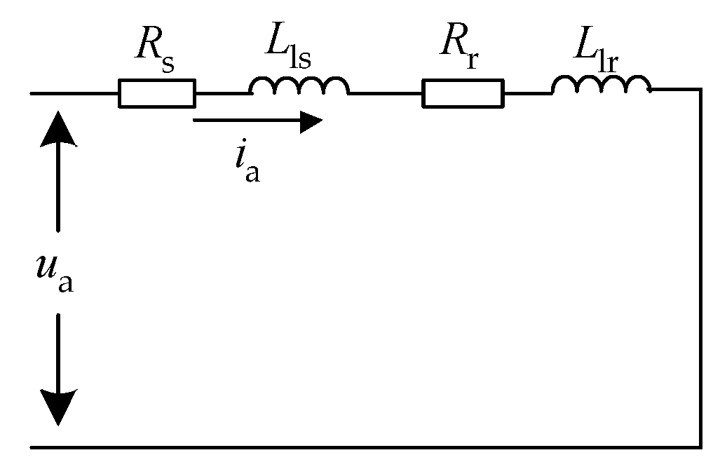
- When the injected voltage frequency is high enough, jωeLm >> Rr + jωeLlr is satisfied, and thus the magnetizing inductance can be neglected, as shown in Figure 4.
- Considering Lls = Llr in the calculation.
- Ignoring the influence of the skin effect on the rotor resistance and the leakage inductance.
2.2.1. Motor Equivalent Circuit Based Methods
If a single-phase AC voltage is supplied to the motor, the AC voltage can theoretically be reconstructed with the switching states and the DC-link voltage, where the AC current of the motor can be measurable. Meanwhile, the phase difference between the voltage and current can be obtained by means of the Fast Fourier Transform (FFT) method. Therefore, the equivalent circuit impedance as well as its real and imaginary parts can be acquired. Accordingly, the motor parameters can be estimated in two ways.
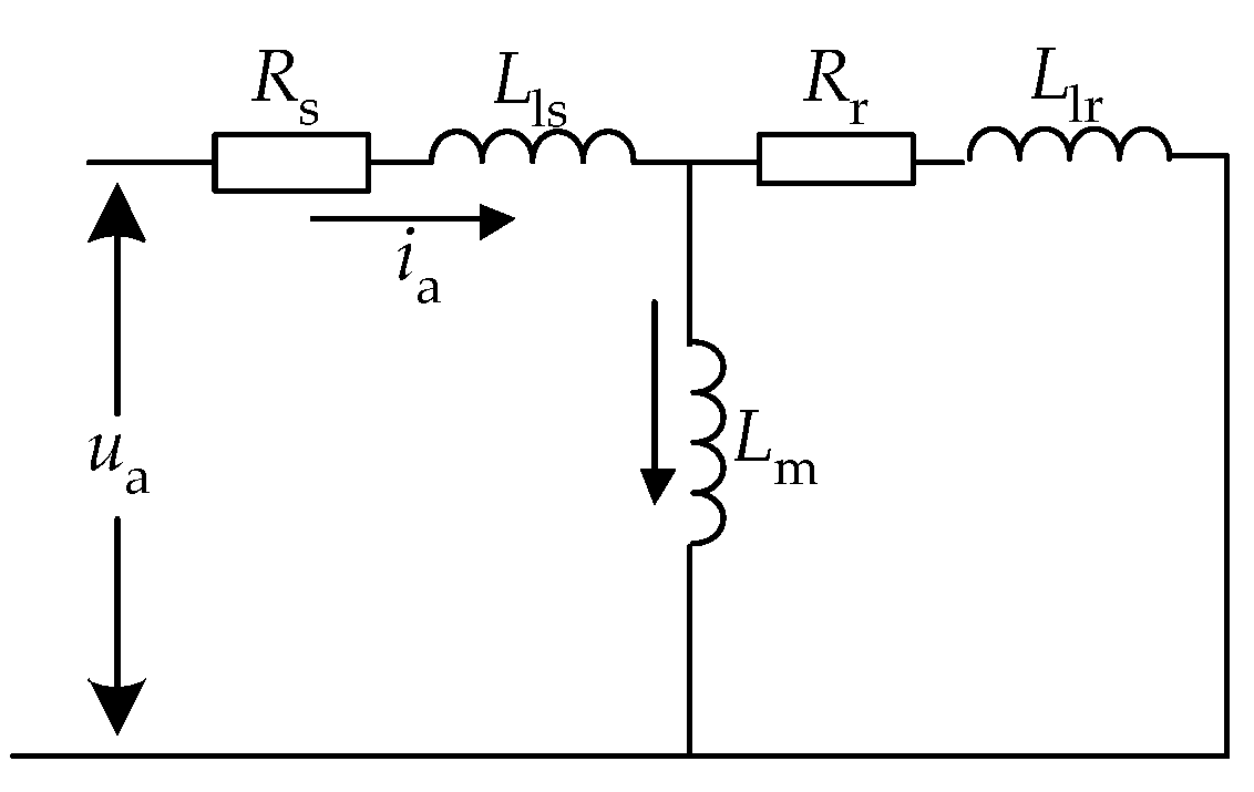
Firstly, seen from Figure 3, all the motor parameters except for the stator resistance Rs can be calculated by injecting two stator AC signals with frequencies being ω1 and ω2 to the motor [22,23,24], where nonlinear equations should be solved. In [23], the calculation procedures based on the T-form circuit, Γ-form circuit, and inverse-Γ-form circuit are discussed in detail. Seen from Figure 4, the equivalent circuit is simplified. Thus, it is easy to calculate the parameters in the equivalent circuit, which is employed in [25]. Compared with the first method mentioned above (see Figure 3), it does not require solving nonlinear equations, and thus the computation burden is less but the results are more precise. However, since the injected AC voltage frequency is relatively high, the influence from the skin effect becomes unignorable.
2.2.2. Recursive Least Square Method
The least square (LS) method can also be applied to identify the motor parameters offline. The principle of the LS-based identification is to minimize the square of the error between the actual and the estimated parameters, making the estimated parameters converge to the actual values. Then, parameters are identified. Instead of solving large matrix equations, the iterative approach of the recursive least square (RLS) is developed as
where N is an integer related to the discrete time, θ is the unknown parameters (to be identified), y is the measurements, φ depends on the previous input and output samples, P is the covariance matrix. For a linear regression model described as y(N) = φ(N)θ(N), if y and φ are obtained from the model, the parameters in θ can be identified through the RLS by iterating (1). Accordingly, the motor mathematical model for the RLS algorithm at standstill is built up, which can also be found in [26]. In [26], a vector-constructing method was employed to eliminate the differential calculation and digital low-pass filtering, and thus it increases the noise immunity and reduces the complexity.
Although the above methods in the single-phase-AC-injected test can obtain the rotor resistance and leakage inductance, the skin effect of the rotor bar is also significant, leading to inaccurate identification of the rotor resistance and leakage inductance. As aforementioned, since the injected AC signals are usually of high frequency, the skin effect cannot be neglected anymore.
3. Online Parameter Identification
Due to the winding temperature increase, skin effect, and flux saturation, as aforementioned, the electrical parameters are varying during operation. Thus, it is necessary to identify parameters in real-time. Many attempts have been made in the literature, where various techniques are applied. Regardless of these complicated algorithms, simple online compensation methods based on the motor inherent thermal and electromagnetic characteristics are employed. For example, the stator resistance can be adjusted according to the linear temperature-resistance relationship [63], if a thermal sensor (PT100) is embedded in the motor. The magnetizing inductance can be corrected online using the magnetizing current or flux based on the magnetizing curve [8] measured in no-load tests. Even though the compensation approach can obtain motor parameters, it is not universal for all applications. Hence, the algorithms based on the motor mathematical model or artificial intelligence are discussed in the following.
3.1. Recursive Least Square Technique
Among various identification algorithms, the recursive least square (RLS) is widely used, as it is fast, efficient, and easy to implement. The general RLS algorithm is described above in (1). Based on this, an RLS algorithm with a suitable forgetting factor λ was proposed in the literature to improve the identification convergence rate as
where λ defines the weight of the history data. In order to apply the RLS algorithm to IMs for online parameter identification, the mathematical model of the IM operating at the speed of ωr was analyzed in [27,28,29,64], where the assumption of dωr/dt = 0 was made to realize the decoupling between the flux and unknown parameters. Furthermore, a speed constraint was derived in [28] in detail. Moreover, the number of estimated parameters θi (i = 1, 2, 3, 4, 5) is more than the number of the independent electrical parameters, where the non-linear relationship of θ3/θ2 = θ4/θ5 can be found among the estimated parameters according to [64] (i.e., it is over-parameterized). Thus, if an unconstrained minimization is employed in the RLS algorithm, it fails to compute θ2 as the second column of the matrix R = φTφ has a very low value, resulting in that the algorithm is highly sensitive to noise, called ill condition (θ2 problem). In order to overcome this problem, solutions were developed in two ways, where either an unconstrained minimization was investigated by considering the constraint θ3/θ2 = θ4/θ5, or a constrained algorithm was involved. For example, Ref. [28] provides two approaches. More specifically, the stator resistance was pre-determined and the original mathematical model for RLS identification is modified; on the other hand, an iterative algorithm was adopted along with the constraint. Furthermore, in [64], a constrained minimization is proposed to guarantee the convergence and accuracy.
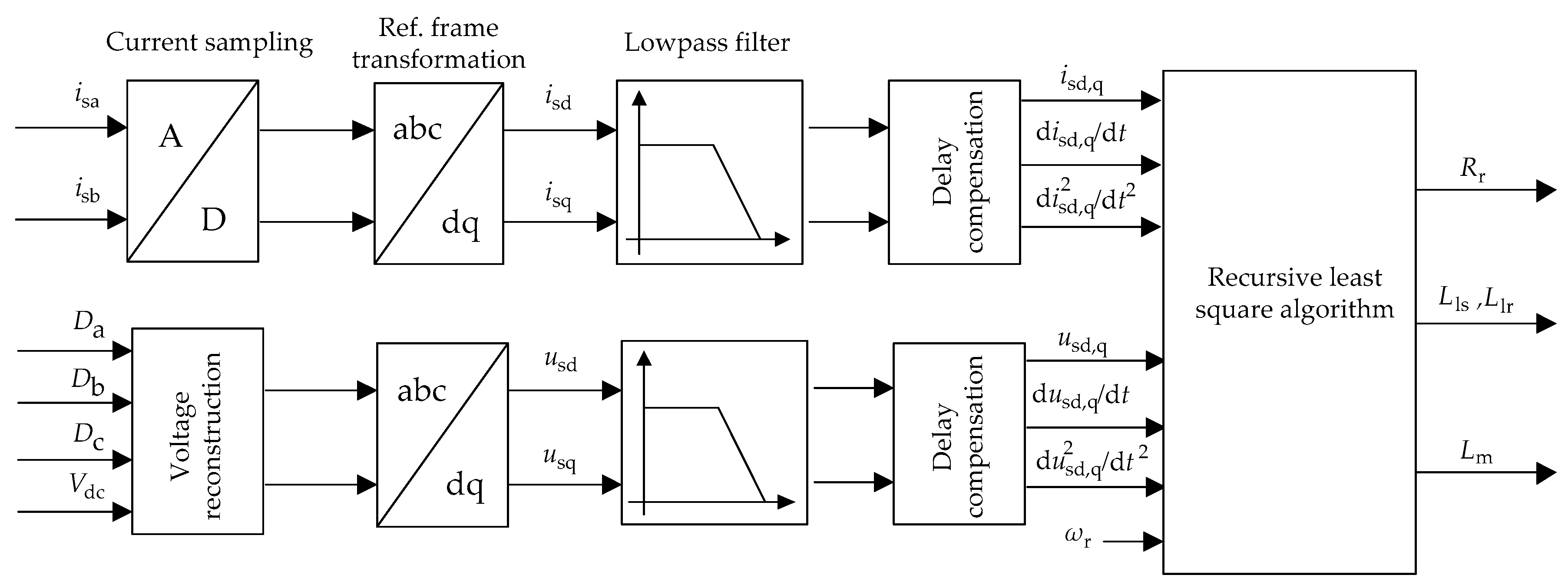
Nonetheless, the RLS estimation algorithm requires the following inputs: the stator currents, voltages, and their derivatives. Here, the currents can be measured, while the voltages are reconstructed using the switching states and the DC voltage. Due to the noise and harmonics in these inputs, filters are necessary but introduce delays, which thus should be compensated. To achieve accurate identification of motor parameters, various filters are developed or employed in the literature, including the Bessel low-pass analog filters, digital finite-impulse response (FIR) differentiator filters [27,64], Butterworth filters [28], and Chebysheve’s filters [29]. The detailed implementation procedure of the RLS algorithm is shown in Figure 5.
Furthermore, the forgetting factor will affect the RLS algorithm performance to a large extent. If the forgetting factor decreases, the latest data will largely affect the results. Thus, the identified parameters converge quickly, while the stability is reduced; i.e., the algorithm is apt to diverge. On the contrary, if the forgetting factor increases, the convergence process is slower, and consequently, the identification takes more time to track the actual values while the stability is improved. In particular, when the forgetting factor is set to 1, the estimation algorithm will degenerate to the conventional RLS. Hence, an appropriate forgetting factor should be set considering the tradeoff between the convergence rate and the algorithm stability. In general, the forgetting factor can be determined within 0.9 to 1.0.
3.2. Model Reference Adaptive System Technique
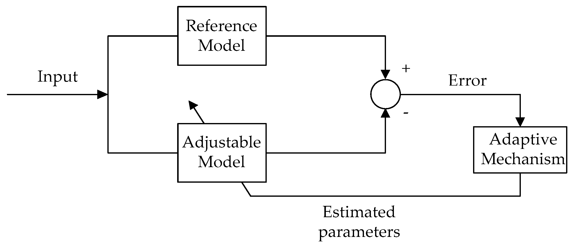
The model reference adaptive system (MRAS) technique is a relatively matured method, which has been applied in parameter identification due to its simple structure and easy implementation. The basic principle of the MRAS is described in Figure 6. As observed in Figure 6, an actual motor is included as the reference model, while the motor mathematical model that contains the unknown parameters is taken as the adjustable model. The inputs of the two models are the same. Through an adaptive law, the estimated parameters will converge to their true values by driving the error vector between the outputs of the reference and adaptive models to zero. Therefore, the unknown parameters can be identified online by applying the MRAS.
Based on the error signal formulation in the MRAS model, various MRAS-based identification methods are investigated; e.g., the methods based on the electromagnetic torque [30,31,32,33], rotor flux [34], stator voltage [31,35], active power [30,31,32,33], reactive power [30,31,32,33,36], back electromagnetic field (EMF) [34], etc. In [32,33], the applications of the instantaneous active power, reactive power, and electromagnetic torque for the rotor resistance identification were discussed. In this case, the reference models are based on real measurements of the motor current, while the adaptive models are based on the observer results of the motor mathematical model. In addition, in [37], a unified adaptive model was presented. Different configuration parameters in the unified model correspond to various functional candidates to derive the reference and adjustable models for the MRAS identification, where the dq rotor flux, dq stator voltage, electromagnetic torque, active and reactive power are included.
Clearly, one of the key issues of the MRAS techniques is to design the adaptive law. Usually, the Popov’s and Lyapunov’s criteria are employed to derive the adaptive mechanisms. Meanwhile, it is indicated that the two criteria are actually equivalent in terms of designing the adaptive scheme for the MRAS identification method. As a result, the parameters are estimated according to the criteria, where a proportional-integral (PI) or integral (I) controller is typically adopted.
Most of the MRAS-based identification methods focus on the estimation of the rotor resistance or rotor time constant in the sensor-less speed control systems. Additionally, the stator resistance was also estimated in [65,66]. However, limited by the convergence speed and the algorithm stability, when three or more parameters should be identified at the same time, it is difficult for the MRAS-based parameter identification techniques to find a suitable adaptive law that satisfies the stability criteria. In other words, the MRAS-based parameter identification methods have difficulty in identifying more motor parameters.
3.3. Signal Injection Based Technique
When a DC or AC offset voltage is added to the voltage reference for the IM, the motor parameters can be calculated by extracting the superimposed voltage and current. Although the injected voltage components may interfere the motor drive system, methods based on the signal injection to identify motor parameters have attracted much popularity due to their high robustness against measurement errors. In the following, the DC signal injection and high-frequency AC signal injection methods are discussed.
3.3.1. DC-Signal Injection
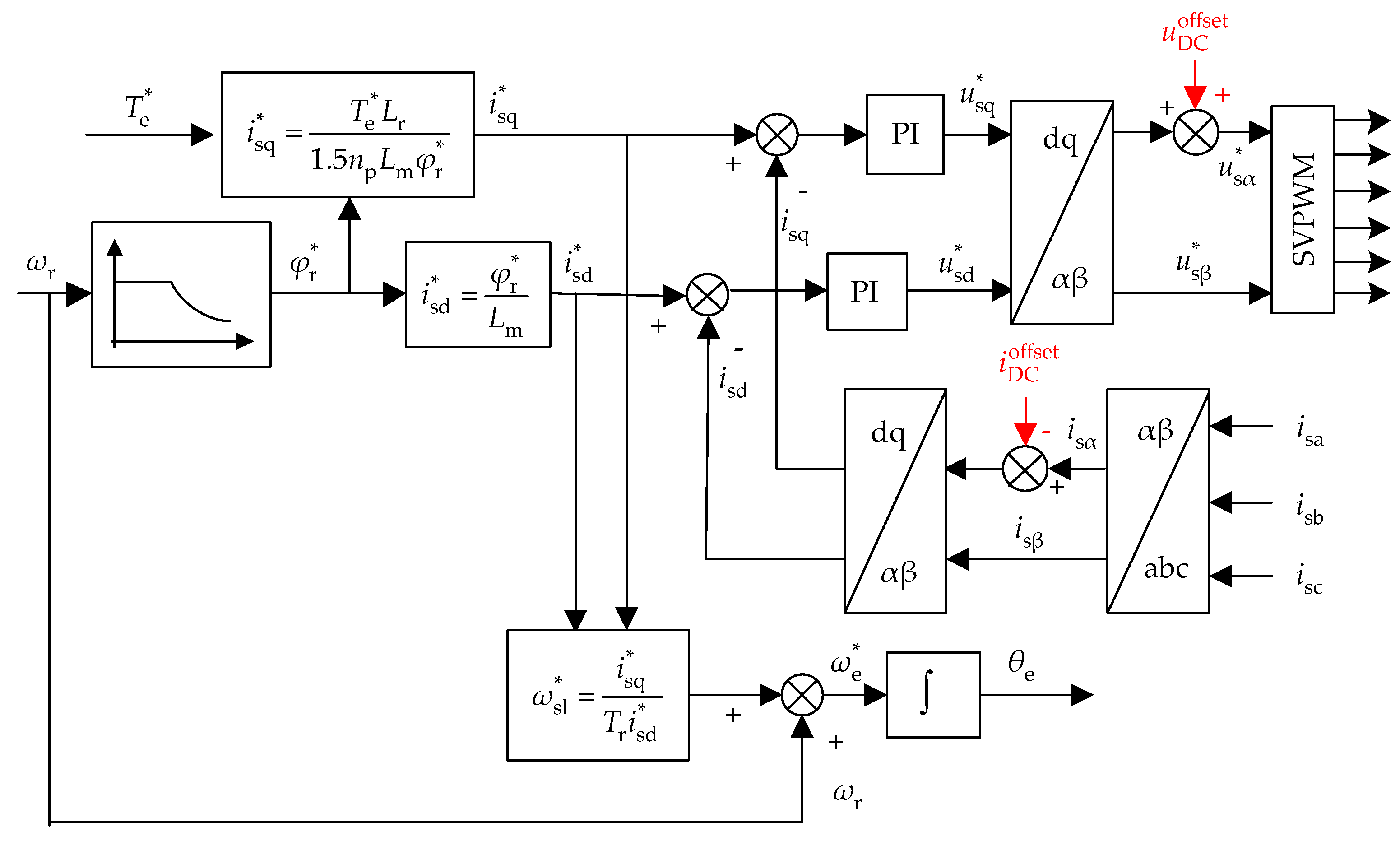
A DC offset voltage can be applied to the motor by superimposing a DC component into the stator voltage reference in the αβ- or abc-reference frame [38]. Figure 7 exemplifies the implementation of the DC-signal injection in the αβ-reference frame for online parameter identification. With this method, the stator resistance can be calculated according to the ratio of the applied DC offset voltage and the DC bias current as
where is the DC offset voltage and is the extracted DC bias current (from the measurements). It should be noted that because of the high bandwidth of the current control loop, the DC offset reference voltage will be cancelled out. Therefore, the DC bias current has to be removed from the feedback currents in the closed-loop control system, as shown in Figure 7.
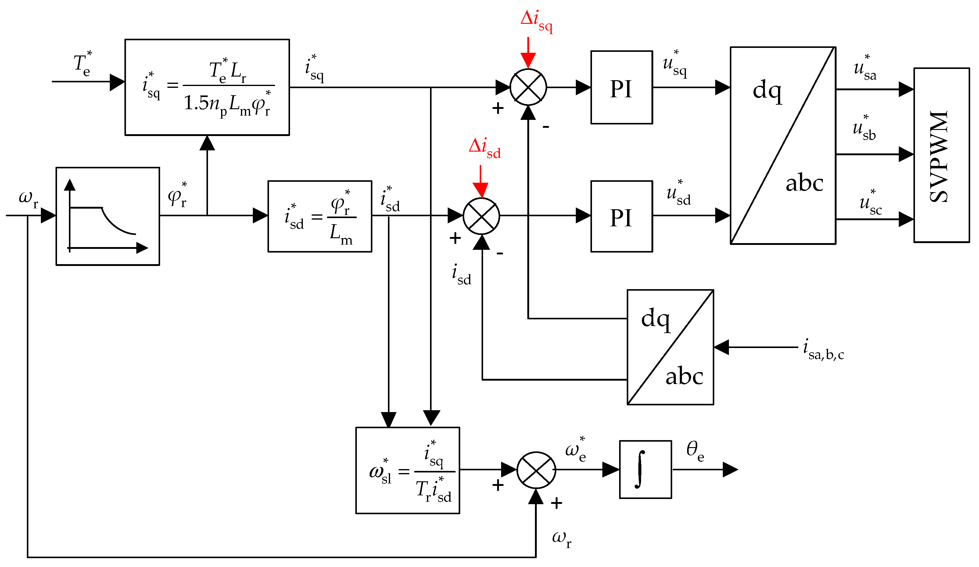
Another method to eliminate the current closed-loop impact focuses on adding a sine-wave current to the current references in the dq-rotating reference frame [11,39], as it is shown in Figure 8. The frequency of the additional currents is the same as the stator angular frequency ωe, and its amplitude is the value of the DC offset current . They can be expressed as
where ∆isd and ∆isq are the currents added to the d-axis and q-axis reference current loop, respectively, as shown in Figure 8.
Since the expected DC offset current is mixed with the fundamental-frequency and harmonic currents, various approaches are developed in the literature to extract the DC component for online parameter identification. For instance, a notch filter was adopted in [11,39] to extract the DC component from the measured current. The rejection bandwidth of the notch filter is narrow, and around the notch frequency (e.g., the fundamental frequency), an infinite negative gain is obtained [67]. Thus, the AC components after the filtering are eliminated, and the desired DC component can be obtained. On the other hand, the mean value method was employed to obtain the DC component in [12]. As it is known, the average value of an AC current is zero during one period, while a DC current will shift the average. Thus, the DC current can be separated from the measured current by averaging it. Furthermore, the inverter non-linearity has an influence on the DC voltage. The effects of dead time, device voltage drop, and turn-on/turn-off delay were discussed and compensated in [11,12].
As shown in Figure 7, the injected DC offset in the αβ-reference frame will be transformed into AC components in the dq-rotating reference frame, leading to extra torque pulsations at the supplied stator frequency. A detailed analysis of the torque pulsation has been presented in [12], where it was further demonstrated that the amplitude of the torque pulsation is proportional to the injected DC current level instead of load-dependence. In order to reduce the torque pulsations, it has been introduced in [68] to inject a second-order harmonic to the current in the αβ-stationary reference frame. Such an algorithm contributes to the mitigation of the q-axis current ripples. In addition, it is worth mentioning that the DC current cannot be injected continuously, since the current will induce extra power losses, resulting in a temperature increase. That is, the DC signal should be periodically injected to avoid significant power losses [39].
Furthermore, the motor temperature can also be obtained from the estimated stator resistance according to the linear relationship [63] as
where R and R0 are the resistances at the temperatures T and T0, respectively, k being the temperature coefficient, R0 and T0 are the initial values, and R and T are the estimated.
3.3.2. High Frequency Carrier Signal Injection
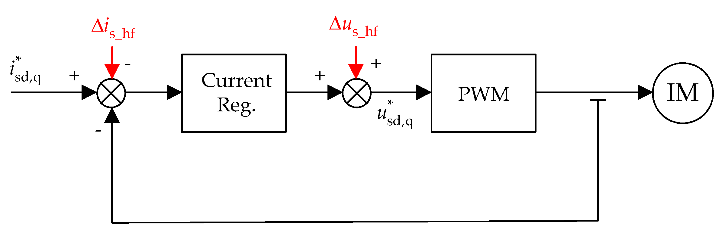
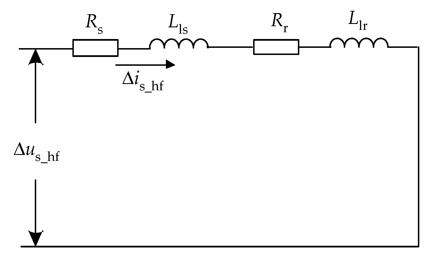
Similarly, a high-frequency carrier voltage can be applied to the motor by superimposing a high-frequency AC component to the voltage references [40,41], as shown in Figure 9. If the frequency fh is high enough, the slip frequency for the high frequency component is considered to approach 1, i.e., s = (fh − fr)/fh ≈ 1. In this case, the equivalent model of the injected high frequency component [42] is derived as shown in Figure 10. Therefore, the rotor resistance and leakage inductance can be calculated by using the high-frequency carrier voltage ∆us_hf and current ∆is_hf. Meanwhile, the high-frequency carrier current should be extracted from the measured current. To do so, in [40], a band-stop filter was employed to remove the fundamental-frequency current. In addition, other options by means of a band-pass filter or fast Fourier transform (FFT) are also possible to separate the high frequency carrier current from the measurements, as discussed in [40].
Furthermore, delays appear due to the current sampling, computation, and PWM processing in digital control systems [69]. Such delays will bring phase errors between the high-frequency voltage and current. Therefore, in [42], the online phase delay compensation was presented under different frequencies. Although the high frequency signal injection method can identify most of the motor parameters, the carrier frequency is usually at 200 Hz or above, resulting in that the switching frequency of the inverter should be higher to avoid the carrier distortion. Therefore, the method based on the high frequency carrier signal injection is not as popular as the DC signal injection approach for online parameter identification in IMs.
3.4. Observer Based Technique
An observer can also be employed to identify motor parameters. Basically, the observer outputs are subtracted by the motor actual measurements, and then multiplied with a matrix L. Subsequently, the multiplication is added to the state equations of the observer, resulting in a so-called Luenberger observer as
where ^ represents the estimated variables, x(t) is the state variables, y(t) is its outputs, and u(t) is the inputs at time t. For the IM parameter identification, as the motor model is nonlinear, it is then approximated using the Taylor expansion to linearize the model around the previous estimated state. To ensure the validity of this process, the linearization should be a good approximation of the nonlinear model. With these considerations, extended Luenberger observers (ELO) were proposed to identify motor parameters in [43,44,45,46], where the unknown parameters were augmented to state variables. Thus, the dimension of the state variables was expanded. More specifically, in [43], a full-order extended Luenberger observer (FELO) and a reduced order extended Luenberger observer (RELO) for the IM parameter identification were derived, where a joint flux-speed observer and a joint flux-rotor time constant observer were also employed. Furthermore, in [46], three different FELOs related to the motor parameters were implemented and validated.
Additionally, the extended Kalman filter (EKF) is an optimization algorithm that can overcome the noise sensitivity issues in the RLS algorithm. Similar to the ELO, the EKF attempts to address the nonlinear issue using a linear approximation, where the linearization of the current state estimation is performed. For the IM parameter identification, there are the inherent nonlinearities in the IM, and however, the EKF is well suitable to process nonlinearities. Thus, it is feasible for the parameter identification. In general, there are prediction and filtering stages in the EKF algorithm, where the future predicted states are determined in the prediction stage and the estimated states are obtained by adding corrections to the predicted states. A detailed EKF algorithm was discussed in [47] to estimate the inverse rotor time constant according to the measured stator currents and rotor speed. In this case, the magnetizing inductance was obtained through a look-up table according to the function between the magnetizing current and inductance. Furthermore, in [49], the EKF and RLS were combined to identify motor parameters, where the former (i.e., the EKF algorithm) focuses on the rotor resistance and the latter (i.e., the RLS algorithm) is dedicated to the estimation of the rotor inertia constant, damping constant, and disturbed load torque. However, the implementation of the EKF demands a high computational burden. Therefore, many solutions were demonstrated to overcome this problem in the literature. For instance, in [48], a reduced-order EKF model was presented to lower the computation efforts to approximately one third of that demanded by the full-order EKF. Furthermore, Barut et al. have made more efforts on the estimation problem in terms of the stability and computation [50,51]. More specially, in [50], the “braided” EKF algorithm that consists of two EKFs was demonstrated to estimate the stator resistance and rotor resistance. As there are two EKF models in this algorithm, the estimated parameter Rs or Rr in the previous EKF model is then passed on to the next EKF model, where it is considered to be constant in the process. In [51], a bi-EKF algorithm was proposed for the rotor and stator resistance estimation, in which a single EKF algorithm was employed. More specifically, based on two extended IM models, the single EKF algorithm uses consecutively two inputs. As a result, less memory is required than the previous “braided” EKF algorithm.
Another observer—the sliding mode observer (SMO)—employs the non-linear high-gain feedback in a way that the estimated states are driven to a hypersurface. In the hypersurface, theoretically, the estimated output and the measured match well. In this observer, the non-linear gain is typically implemented with a switching function as
where x indicates the error between the observed states and measurements. Compared to the Kalman filter, the SMO algorithms are also of high attractiveness, but the implementation is relatively simpler. An SMO-based parameter identification method can provide high robustness, where a suitable adaptive law should be employed. In [8], an SMO with the Popov’s hyper-stability theory was developed to estimate the rotor speed and stator resistance, where the magnetizing inductance was given according to a predetermined magnetizing curve. Furthermore, a Luenberger-SMO along with the Lyapunov’s function was adopted to estimate the stator and rotor resistance, where the errors between the estimated and measured were multiplied by the Luenberger gain and the sliding-mode gain for the feedback correction in [53,54]. In this case, the Luenberger observer corrects the estimated values, while the sliding mode term determines the robustness of the observer. Nevertheless, with an appropriate observer, the motor parameters can be identified online with high robustness.
3.5. Other Methods
In addition to the above parameter identification methods for IMs, there are other online parameter identification possibilities based on the artificial intelligence technique; e.g., artificial neural network (ANN), genetic algorithm (GA), and machine learning. When using an ANN algorithm for parameter identification [55,56,57,58,59], the type of the neutral network and the number of the layers should be determined first. Online training based on a learning rule will then be processed to minimize the error function, and consequently, the weights can be adjusted to calculate the parameters. For example, in [59], a two-layer feed-forward neural network was investigated, where a back-propagation technique was adopted to train the algorithm for the rotor resistance identification. In contrast, in this case, the stator resistance was separately estimated using a recurrent neural network. Moreover, the GA is a searching algorithm based on the natural selection and evolution. It is of high robustness and thus, the GA is widely applied in global optimization. Since the GA is not limited by the abilities (e.g., continuity, differentiability), it can decompose complex issues that the traditional algorithm cannot solve, showing its great potential in estimating motor parameters. Such a possibility can be found in [60,61,62]. However, because of the low convergence rate, it is difficult to apply the GA in practical online applications. Lastly, with the declining price of data storage, a large amount of historical data can be stored and processed. In that case, machine-learning techniques may emerge in the parameter identification of IM systems. Nevertheless, according to the above discussions, a summary of the parameter identification methods for IMs is presented in Table 1 in terms of typical identified-parameters and implementation issues, where rotor time constant Tr = Lr/Rr.
4. Simulation Results
In this section, in order to verify the feasibility, accuracy, and dynamic performance of the discussed algorithms, an example inverter-fed IM system is adopted to show the simulation results in MATLAB. On one hand, the methods based on the recursive least square, model reference adaptive system, and DC injection are commonly used and easily implemented. On the other hand, seen from Table 1, only one or certain specific parameters are obtained from each method, and thus it is insufficient to obtain a number of parameters if only one method is applied. Therefore, methods based on the RLS, MRAS, and DC signal injection are selected to provide their identification results by considering parameter variations in this section. It should be noted that certain parameters of the algorithms should be tuned properly according to requirements in practice. Nevertheless, the simulations are performed to demonstrate the algorithms. The nominal parameters of the IM are shown in Table 2, and the switching frequency of the inverter is 1 kHz. In the simulation model, the stator leakage inductance and rotor leakage inductance cannot be separated, and thus Lls = Llr is considered.
4.1. Offline Recursive Least Square Method
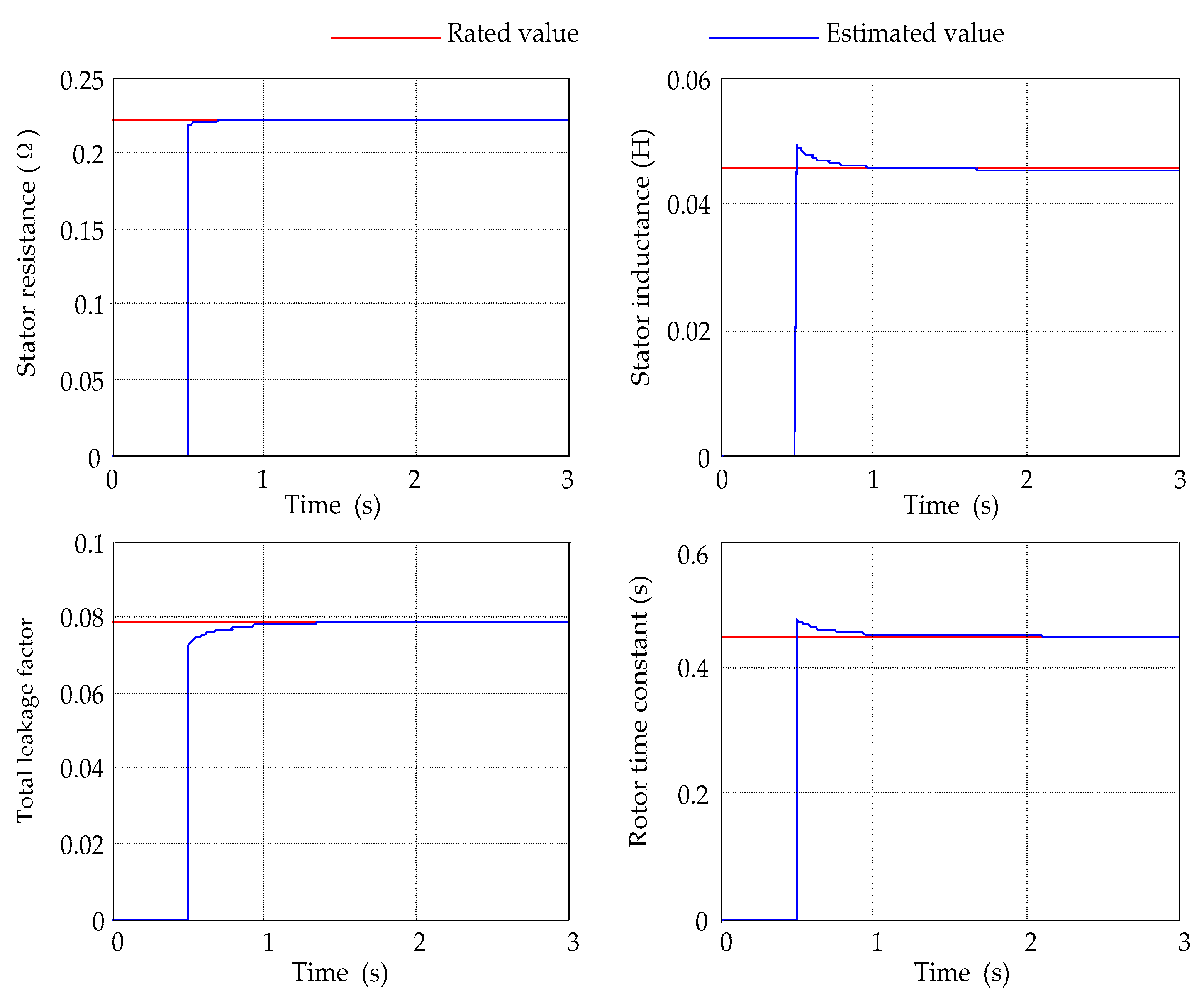
The offline RLS method is firstly implemented in simulations, where the frequency of the supplied single-phase-AC voltage is 50 Hz. The Butterworth filter is utilized and discretized by the Euler method to the obtained voltage, current, and their derivatives for further calculation. The estimated parameters are shown in Figure 11. Since there is a tuning period of the RLS algorithm, the estimated parameters shown in Figure 11 are demonstrated from t = 0.5 s. As it can be observed in Figure 11, the estimated values converge to the nominal values after some iterations. The final estimated values as well as the percentage errors are provided in Table 3. It is demonstrated in Table 3 that the errors are always below 0.8%, thus the offline RLS algorithm can accurately identify the motor parameters. In practice, due to nonlinearity, the estimation accuracy may be degraded, and therefore, certain nonlinearity compensation methods should be adopted.
4.2. Online Recursive Least Square
The online RLS technique in the dq-reference frame is applied to the motor according to [28], and the related parameter configuration is as follows:
- The cut-off angular frequency of the Butterworth filter is 200 rad/s.
- The forgetting factor is set to 0.95.
- The initial values of parameters are set to zero.
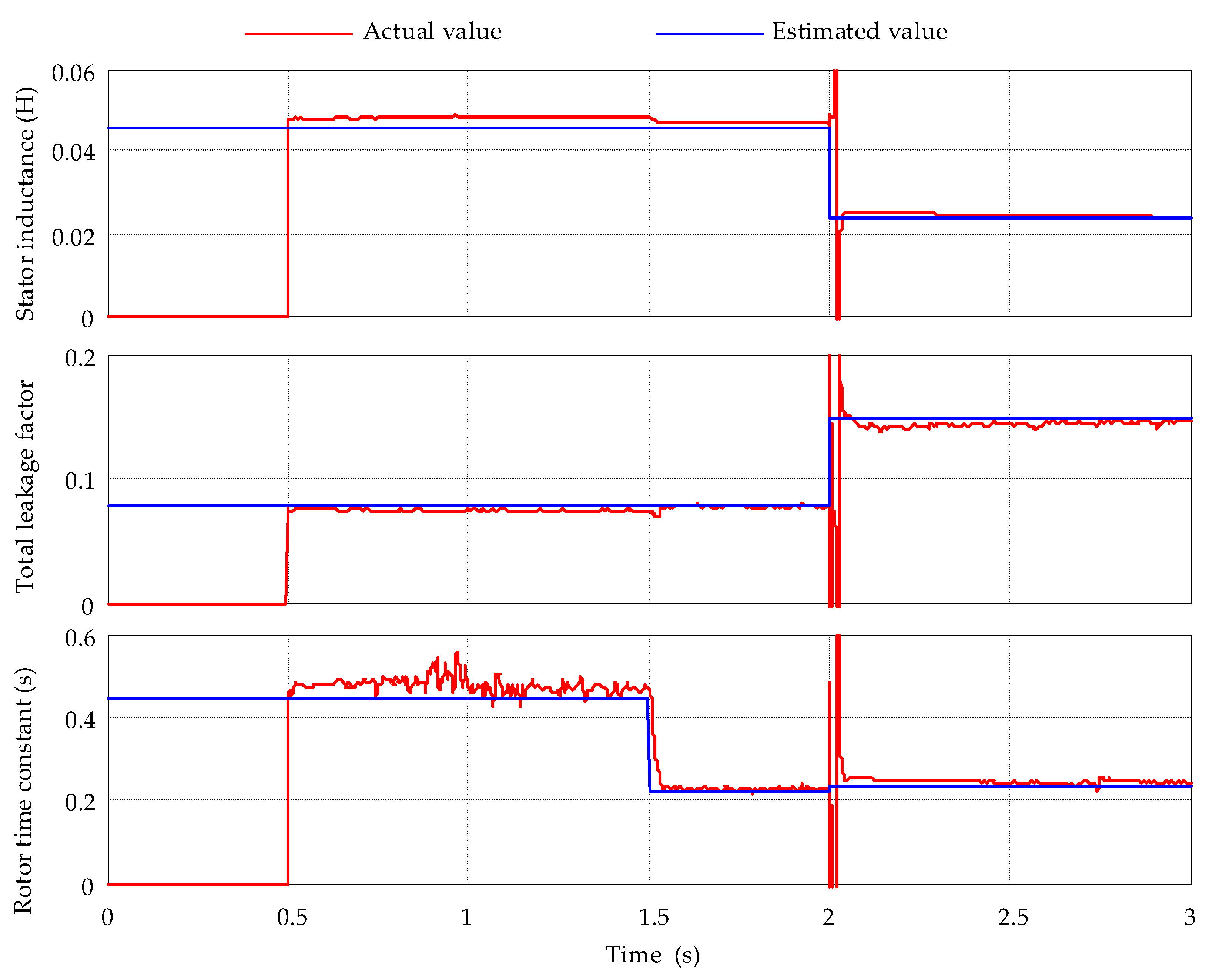
When the stator resistance is considered first, the corresponding online estimated parameters are shown in Figure 12. Similarly, there is an adjusting period for the online RLS technique, and thus, the results are presented from t = 0.5 s.
Due to the impacts of the temperature, skin effect, and flux saturation, parameters are changing during the motor operation in practice. To validate the dynamic response of the online RLS algorithm, parameter step variations are imposed through the motor model in the simulation to represent the extreme situation in the simulation. Accordingly, the rotor resistance increases to two times at t = 1.5 s, and on the contrary, the magnetizing inductance decreases to a half at t = 2.0 s. It can be observed in Figure 12 that the performance of the online RLS technique is very good, since the estimated values approach the actual values although it takes some iterations to follow the new changed parameters. The estimated values along with parametric error are summarized in Table 4. It can be seen in Table 4 that the steady-state error is small, and thus, the online RLS algorithm can identify parameters accurately in real time, where the nonlinearity should be considered. In addition, seen from Figure 12, there is a slight fluctuation in the estimated rotor time constant from 0.5 s to 1.5 s, but the error is in a reasonable range.
4.3. Model Reference Adaptive System
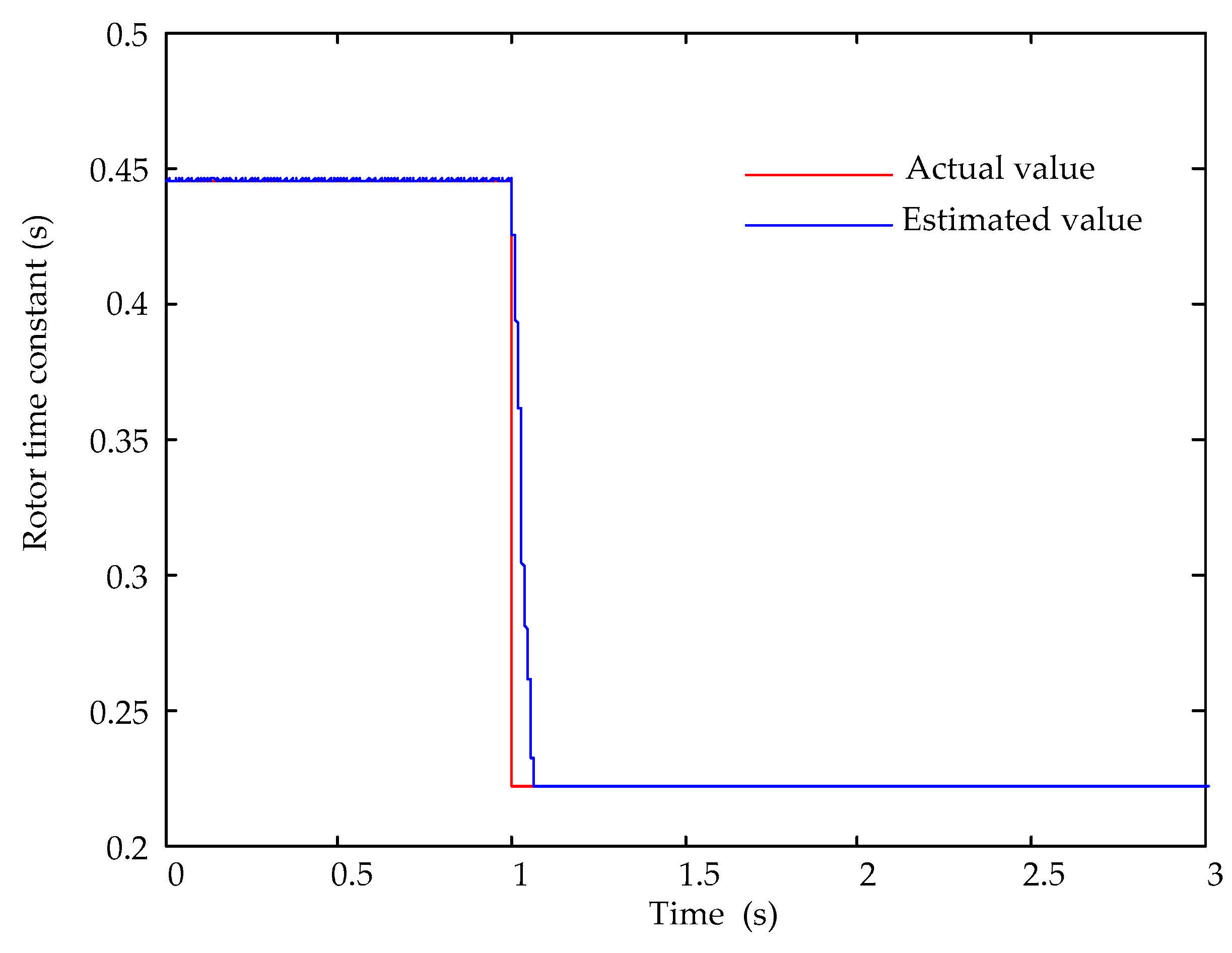
The MRAS method based on rotor flux models is performed to estimate the motor parameter (i.e., the rotor time constant) according to [34]. In order to verify the effectiveness and feasibility of the MRAS method, the rotor resistance is changed from the rated value to two times of the rated at t = 1 s. The corresponding estimated rotor time constant is shown in Figure 13, where kp = 0.001 and ki = 0.1 are the proportional and integral gains of the PI controller, respectively. The estimated value converges to the actual value in a short period. Accordingly, the actual and estimated parameters are respectively 0.22699 Ω and 0.22260 Ω at steady state. It can be observed in Figure 13 that the estimated line almost overlaps with the rated curve, and thus the estimated error at steady state is small.
4.4. DC Signal Injection
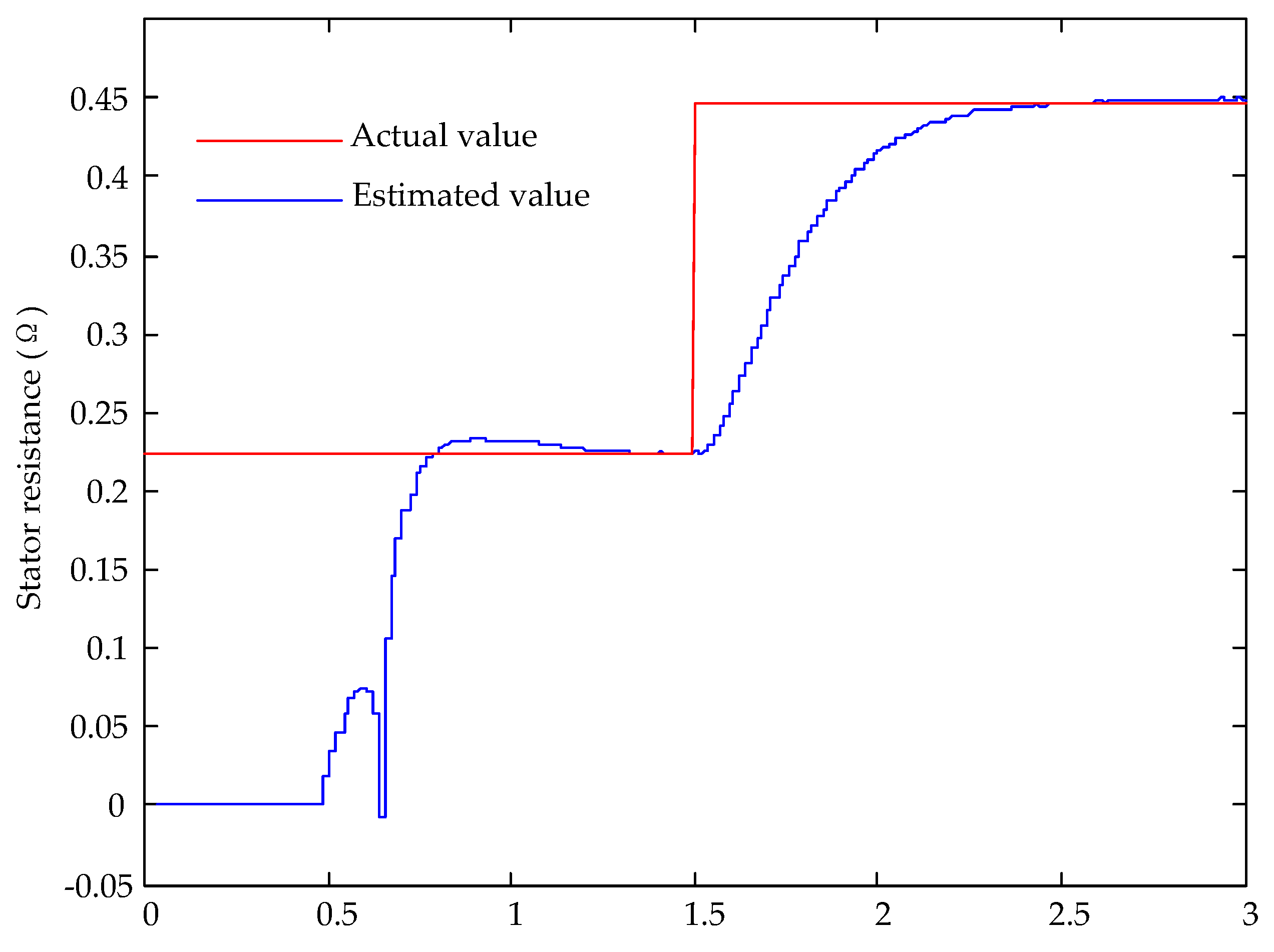
The algorithm in [11] is applied to the motor to identify the stator resistance, where the injected DC current is chosen as 10 A. With the injection occurring at t = 0.5 s, the stator resistance can be calculated by measuring the DC offset voltage and current. The result is shown in Figure 14, where the sharp decrease of the command torque leads to a fluctuation of the estimated stator resistance at around t = 0.6. As the responsive DC bias current requires a period to reach the steady state because of the motor inductance, the estimated stator resistance follows the rated value at t = 1.5 s. Then, a step variation of the stator resistance is applied, and it takes almost 1 s to track the actual value. Compared to the actual resistance Rs = 0.446 Ω, the estimated Rs = 0.4414 Ω at steady state is within an error of 1%. Accordingly, it is very clear that the DC signal injection method can obtain very high precision, and the effectiveness of the method is verified.
From the above-discussed algorithms, the percentage errors of the estimated parameters at steady state are further summarized as shown in Table 5. Among these methods, the offline RLS can provide precise results. However, further online identification techniques should be used to track parameter variations in practice. By contrast, the online RLS identification algorithm has less accuracy. When the MRAS or DC-signal injection method is adopted, only one parameter can be identified, and the identification result is relatively accurate. In addition, the DC signal injection has the slowest response because of the magnetizing inductance, whereas the response time of the MRAS relies on the values of kp and ki, as demonstrated in the above simulations. The online RLS algorithm can converge to the steady state after a few iterations. As a consequence, in all, if several electrical parameters of IMs are expected to be obtained, different algorithms should be combined to exploit their characteristics in practice.
5. Conclusions
The control performance of induction motors highly depends on the knowledge of motor parameters. Many attempts have thus been made for offline parameter identification, and they are mainly divided into the DC-excited-based and single-phase-AC-injection-based methods. However, due to the temperature change in motors, skin effect, and also flux saturation, motor parameters are varying during operation. In this case, offline parameter identification methods lose the effectiveness. That is, the motor control performance cannot be ensured. Therefore, online parameter identification algorithms have been developed to obtain the motor parameters in real-time. For the online parameter identification, it can be achieved mainly using the recursive least square method, the model reference adaptive system, the signal injection, and additional observers. This paper aims at providing a review of offline and online parameter identification techniques for motor drive applications. The basic principle of the above methods was illustrated in this paper, and the main implementation issues and solutions were also discussed. In order to demonstrate these techniques, simulations on an induction motor with the discussed parameter identification methods were performed.
Author Contributions
All authors contributed equally to this paper, whereby the corresponding author was responsible for the writing, figures and literature research and the second author for organizing, reviewing, and proof reading of the entire contribution.
Funding
This research was funded by the Fundamental Research Funds for the Central Universities (2017YJS187, 2018JBZ004).
Acknowledgments
The author would like to thank the editor and the reviewers who provided many helpful comments and thereby contributed to the final manuscript.
Conflicts of Interest
The authors declare no conflict of interest.
References
- Henke, M.; Narjes, G.; Hoffmann, J.; Wohlers, C.; Urbanek, S.; Heister, C.; Steinbrink, J.; Canders, W.-R.; Ponick, B. Challenges and Opportunities of Very Light High-Performance Electric Drives for Aviation. Energies 2018, 11, 344. [Google Scholar] [CrossRef]
- Bose, B.K. Modern Power Electronics and AC Drives; Prentice-Hall: Englewood Cliffs, NJ, USA, 2002; ISBN 0-13-016743-6. [Google Scholar]
- Takahashi, I.; Ohmori, Y. High-performance direct torque control of an induction motor. IEEE Trans. Ind. Appl. 1989, 25, 257–264. [Google Scholar] [CrossRef]
- Kazmierkowski, M.P.; Kasprowicz, A.B. Improved direct torque and flux vector control of PWM inverter-fed induction motor drives. IEEE Trans. Ind. Electron. 1995, 42, 344–350. [Google Scholar] [CrossRef]
- Zhang, Y.; Bai, Y.; Yang, H. A Universal Multiple-Vector-Based Model Predictive Control of Induction Motor Drives. IEEE Trans. Power Electron. 2018, 33, 6957–6969. [Google Scholar] [CrossRef]
- Zhang, Y.; Yang, H.; Xia, B. Model-Predictive Control of Induction Motor Drives: Torque Control versus Flux Control. IEEE Trans. Ind. Appl. 2016, 52, 4050–4060. [Google Scholar] [CrossRef]
- Liu, L.; Du, X.; Shen, S. Indirect field-oriented torque control of induction motor considering magnetic saturation effect: Error analysis. IET Electr. Power Appl. 2017, 11, 1105–1113. [Google Scholar] [CrossRef]
- Zaky, M.S.; Khater, M.M.; Shokralla, S.S.; Yasin, H.A. Wide-Speed-Range Estimation with Online Parameter Identification Schemes of Sensorless Induction Motor Drive. IEEE Trans. Ind. Electron. 2009, 56, 1699–1707. [Google Scholar] [CrossRef]
- Marcetic, D.P.; Vukosavic, S.N. Speed-Sensorless AC Drives with the Rotor Time Constant Parameter Update. IEEE Trans. Ind. Electron. 2007, 54, 2618–2625. [Google Scholar] [CrossRef]
- Zhang, P.; Lu, B.; Habetler, T.G. An Active Stator Temperature Estimation Technique for Thermal Protection of Inverter-Fed Induction Motors with Considerations of Impaired Cooling Detection. IEEE Trans. Ind. Appl. 2010, 46, 1873–1881. [Google Scholar] [CrossRef]
- Cheng, S.; Du, Y.; Restrepo, J.A.; Zhang, P.; Habetler, T.G. A Nonintrusive Thermal Monitoring Method for Induction Motors Fed by Closed-Loop Inverter Drives. IEEE Trans. Power Electron. 2012, 27, 4122–4131. [Google Scholar] [CrossRef]
- Matić, P.R.; Gecić, M.A.; Lekić, D.M.; Marčetić, D.P. Thermal Protection of Vector-Controlled IM Drive Based on DC Current Injection. IEEE Trans. Ind. Electron. 2015, 62, 2082–2089. [Google Scholar] [CrossRef]
- Abdallah, H.; Benatman, K. Stator winding inter-turn short-circuit detection in induction motors by parameter identification. IET Electr. Power Appl. 2017, 11, 272–288. [Google Scholar] [CrossRef]
- Cho, K.R.; Lang, J.H.; Umans, S.D. Detection of broken rotor bars in induction motors using state and parameter estimation. IEEE Trans. Ind. Appl. 1992, 28, 702–709. [Google Scholar] [CrossRef]
- Lee, S.H.; Yoo, A.; Lee, H.-J.; Yoon, Y.-D.; Han, B.-M. Identification of Induction Motor Parameters at Standstill Based on Integral Calculation. IEEE Trans. Ind. Appl. 2017, 53. [Google Scholar] [CrossRef]
- Sumner, M.; Asher, G.M. Self-commissioning for voltage-referenced voltage fed vector controlled induction motor drives. In Proceedings of the Power Electronics Specialists Conference, Toledo, Spain, 29 June–3 July 1992; pp. 139–144. [Google Scholar]
- Sumner, M.; Asher, G.M. Auto commissioning for voltage-referenced voltage-fed vector-controlled induction motor drives. IEE Proc. Electr. Power Appl. 1993, 140, 187–200. [Google Scholar] [CrossRef]
- Kwon, W.H.; Lee, C.H.; Youn, K.S.; Cho, G.H. Measurement of rotor time constant taking into account magnetizing flux in the induction motor. In Proceedings of the 1994 IEEE Industry Applications Society Annual Meeting, Denver, CO, USA, 2–6 October1994; pp. 88–92. [Google Scholar]
- Jeong, S.-G.; Park, M.-H. The analysis and compensation of dead-time effects in PWM inverters. IEEE Trans. Ind. Electron. 1991, 38, 108–114. [Google Scholar] [CrossRef]
- Sukegawa, T.; Kamiyama, K.; Mizuno, K.; Matsui, T.; Okuyama, T. Fully digital, vector-controlled PWM VSI-fed AC drives with an inverter dead-time compensation strategy. IEEE Trans. Ind. Appl. 1991, 27, 552–559. [Google Scholar] [CrossRef]
- Munoz, A.R.; Lipo, T.A. On-line dead-time compensation technique for open-loop PWM-VSI drives. IEEE Trans. Power Electron. 1999, 14, 683–689. [Google Scholar] [CrossRef] [Green Version]
- Zheng, J.; Wang, Y.; Qin, X.; Zhang, X. An offline parameter identification method of induction motor. In Proceedings of the 2008 7th World Congress on Intelligent Control and Automation, Chongqing, China, 25–27 June 2008; pp. 8898–8901. [Google Scholar]
- Gastli, A. Identification of induction motor equivalent circuit parameters using the single-phase test. IEEE Trans. Energy Convers. 1999, 14, 51–56. [Google Scholar] [CrossRef]
- Shen, G.; Wang, K.; Yao, W.; Lee, K.; Lu, Z. DC biased stimulation method for induction motor parameters identification at standstill without inverter nonlinearity compensation. In Proceedings of the 2013 IEEE Energy Conversion Congress and Exposition, Denver, CO, USA, 15–19 September 2013; pp. 5123–5130. [Google Scholar]
- Luo, H.; Liu, J.; Wan, S. Off-line Identification of Induction Motor Parameters. Electr. Drive 2006, 8, 16–21. [Google Scholar] [CrossRef]
- He, Y.; Wang, Y.; Feng, Y.; Wang, Z. Parameter Identification of an Induction Machine at Standstill Using the Vector Constructing Method. IEEE Trans. Power Electron. 2012, 27, 905–915. [Google Scholar] [CrossRef]
- Cirrincione, M.; Pucci, M. Experimental verification of a technique for the real-time identification of induction motors based on the recursive least-squares. In Proceedings of the 7th International Workshop on Advanced Motion Control. Proceedings (Cat. No. 02TH8623), Maribor, Slovenia, 3–5 July 2002; pp. 326–334. [Google Scholar]
- Stephan, J.; Bodson, M.; Chiasson, J. Real-time estimation of the parameters and fluxes of induction motors. In Proceedings of the Conference Record of the 1992 IEEE Industry Applications Society Annual Meeting, Houston, TX, USA, 4–9 October 1992; pp. 578–585. [Google Scholar]
- Alonge, F.; D’Ippolito, F.; Barbera, S.L.; Raimondi, F.M. Parameter identification of a mathematical model of induction motors via least squares techniques. In Proceedings of the 1998 IEEE International Conference on Control Applications (Cat. No.98CH36104), Trieste, Italy, 1–4 September 1998; pp. 491–496. [Google Scholar]
- Mapelli, F.L.; Bezzolato, A.; Tarsitano, D. A rotor resistance MRAS estimator for induction motor traction drive for electrical vehicles. In Proceedings of the 2012 XXth International Conference on Electrical Machines, Marseille, France, 2–5 September 2012; pp. 823–829. [Google Scholar]
- Rowan, T.M.; Kerkman, R.J.; Leggate, D. A simple on-line adaption for indirect field orientation of an induction machine. IEEE Trans. Ind. Appl. 1991, 27, 720–727. [Google Scholar] [CrossRef]
- Kojabadi, H.M. Active power and MRAS based rotor resistance identification of an IM drive. Simul. Model. Pract. Throry 2009, 17, 376–389. [Google Scholar] [CrossRef]
- Dehbozorgi, M.R.; Kojabadi, H.M.; Vahedi, H.; Al-Haddad, K. A comparative study of various MRAS-based IM’s rotor resistance adaptation methods. In Proceedings of the IECON 2012—38th Annual Conference on IEEE Industrial Electronics Society, Montreal, QC, Canada, 25–28 October 2012; pp. 4070–4075. [Google Scholar]
- Munshi, M.; Choudhuri, S.G. Model Reference Adaptive System using Rotor Flux and Back Emf techniques for speed estimation of an Induction Motor operated in Vector Control mode: A comparative study. In Proceedings of the 2016 IEEE Uttar Pradesh Section International Conference on Electrical, Computer and Electronics Engineering (UPCON), Varanasi, India, 9–11 December 2016; pp. 44–49. [Google Scholar]
- Yu, X.; Dunnigan, M.W.; Williams, B.W. A novel rotor resistance identification method for an indirect rotor flux-orientated controlled induction machine system. IEEE Trans. Power Electron. 2002, 17, 353–364. [Google Scholar] [CrossRef]
- Maiti, S.; Chakraborty, C.; Hori, Y.; Ta, M.C. Model Reference Adaptive Controller-Based Rotor Resistance and Speed Estimation Techniques for Vector Controlled Induction Motor Drive Utilizing Reactive Power. IEEE Trans. Ind. Electron. 2008, 55, 594–601. [Google Scholar] [CrossRef]
- Cao, P.; Zhang, X.; Yang, S. A Unified-Model-Based Analysis of MRAS for Online Rotor Time Constant Estimation in an Induction Motor Drive. IEEE Trans. Ind. Electron. 2017, 64, 4361–4371. [Google Scholar] [CrossRef]
- Tshimanga, T.P.; Zhang, S.; Bezabih, E.; He, L.; Iyer, V.; Harley, R.G. Stator temperature estimation of open-loop controlled induction machines via active DC voltage injection. In Proceedings of the 2015 North American Power Symposium (NAPS), Charlotte, NC, USA, 4–6 October 2015; pp. 1–5. [Google Scholar]
- Baneira, F.; Yepes, A.G.; López, Ó.; Doval-Gandoy, J. Estimation Method of Stator Winding Temperature for Dual Three-Phase Machines Based on DC-Signal Injection. IEEE Trans. Power Electron. 2016, 31, 5141–5148. [Google Scholar] [CrossRef]
- Briz, F.; Degner, M.W.; Guerrero, J.M.; Diez, A.B. Temperature Estimation in Inverter-Fed Machines Using High-Frequency Carrier Signal Injection. IEEE Trans. Ind. Appl. 2008, 44, 799–808. [Google Scholar] [CrossRef]
- Reigosa, D.D.; Guerrero, J.M.; Diez, A.B.; Briz, F. Rotor Temperature Estimation in Doubly-Fed Induction Machines Using Rotating High-Frequency Signal Injection. IEEE Trans. Ind. Appl. 2017, 53, 3652–3662. [Google Scholar] [CrossRef]
- Cho, K.-R.; Seok, J.-K. Induction Motor Rotor Temperature Estimation Based on a High-Frequency Model of a Rotor Bar. IEEE Trans. Ind. Appl. 2009, 45, 1267–1275. [Google Scholar] [CrossRef]
- Brdys, M.A.; Du, T. Algorithms for joint state and parameter estimation in induction motor drive systems. Control 1991. In Proceedings of the International Conference on Control 1991. Control ‘91, Edinburgh, UK, 25–28 March 1991; pp. 915–920. [Google Scholar]
- Orlowska-Kowalska, T. Application of extended Luenberger observer for flux and rotor time-constant estimation in induction motor drives. IEE Proc. Control Theory Appl. 1989, 136, 324–330. [Google Scholar] [CrossRef]
- Du, T.; Vas, P.; Stronach, F. Design and application of extended observers for joint state and parameter estimation in high-performance AC drives. IEE Proc. Electr. Power Appl. 1995, 142, 71–78. [Google Scholar] [CrossRef]
- Du, T.; Brdys, M.A. Implementation of extended Luenberger observers for joint state and parameter estimation of PWM induction motor drive. In Proceedings of the 1993 Fifth European Conference on Power Electronics and Applications, Brighton, UK, 13–16 September 1993; pp. 439–444. [Google Scholar]
- Zai, L.-C.; DeMarco, C.L.; Lipo, T.A. An extended Kalman filter approach to rotor time constant measurement in PWM induction motor drives. IEEE Trans. Ind. Appl. 1992, 28, 96–104. [Google Scholar] [CrossRef] [Green Version]
- Atkinson, D.J.; Finch, J.W.; Acarnley, P.P. Estimation of rotor resistance in induction motors. IEE Proc. Electr. Power Appl. 1996, 143, 87–94. [Google Scholar] [CrossRef]
- Lin, F.-J. Robust speed-controlled induction-motor drive using EKF and RLS estimators. IEE Proc. Electr. Power Appl. 1996, 143, 186–192. [Google Scholar] [CrossRef]
- Barut, M.; Bogosyan, S.; Gokasan, M. Experimental Evaluation of Braided EKF for Sensorless Control of Induction Motors. IEEE Trans. Ind. Electron. 2008, 55, 620–632. [Google Scholar] [CrossRef]
- Barut, M.; Demir, R.; Zerdali, E.; Inan, R. Real-Time Implementation of Bi Input-Extended Kalman Filter-Based Estimator for Speed-Sensorless Control of Induction Motors. IEEE Trans. Ind. Electron. 2012, 59, 4197–4206. [Google Scholar] [CrossRef]
- Yang, S.; Ding, D.; Li, X.; Xie, Z.; Zhang, X.; Chang, L. A Novel Online Parameter Estimation Method for Indirect Field Oriented Induction Motor Drives. IEEE Trans. Energy Convers. 2017, 32, 1562–1573. [Google Scholar] [CrossRef]
- Hasan, S.M.N.; Husain, I. A Luenberger-Sliding Mode Observer for Online Parameter Estimation and Adaptation in High-Performance Induction Motor Drives. IEEE Trans. Ind. Appl. 2009, 45, 772–781. [Google Scholar] [CrossRef]
- Kim, J.; Ko, J.; Lee, J.; Lee, Y. Rotor Flux and Rotor Resistance Estimation Using Extended Luenberger-Sliding Mode Observer (ELSMO) for Three Phase Induction Motor Control. Can. J. Electr. Comput. Eng. 2017, 40, 181–188. [Google Scholar] [CrossRef]
- Campbel, J.; Sumner, M. Practical sensorless induction motor drive employing an artificial neural network for online parameter adaptation. IEE Proc. Electr. Power Appl. 2002, 149, 255–260. [Google Scholar] [CrossRef]
- Fodor, D.; Griva, G.; Profumo, F. Compensation of parameters variations in induction motor drives using a neural network. In Proceedings of the 26th Annual IEEE Power Electronics Specialists Conference 1995, Atlanta, GA, USA, 12–15 June 1995; pp. 1307–1311. [Google Scholar]
- Wlas, M.; Krzeminski, Z.; Toliyat, H.A. Neural-Network-Based Parameter Estimations of Induction Motors. IEEE Trans. Ind. Electron. 2008, 55, 1783–1794. [Google Scholar] [CrossRef]
- Karanayil, B.; Rahman, M.F.; Grantham, C. On-line stator and rotor resistance estimation scheme for vector-controlled induction motor drive using artificial neural networks. In Proceedings of the 38th IAS Annual Meeting on Conference Record of the Industry Applications Conference, Salt Lake City, UT, USA, 12–16 October 2003; pp. 132–139. [Google Scholar]
- Karanayil, B.; Rahman, M.F.; Grantham, C. Online Stator and Rotor Resistance Estimation Scheme Using Artificial Neural Networks for Vector Controlled Speed Sensorless Induction Motor Drive. IEEE Trans. Ind. Electron. 2007, 54, 167–176. [Google Scholar] [CrossRef]
- Alonge, F.; D’Ippolito, F.; Ferrante, G.; Raimondi, F.M. Parameter identification of induction motor model using genetic algorithms. IEE Proc. Control Theory Appl. 1998, 145, 587–593. [Google Scholar] [CrossRef]
- Pillay, P.; Nolan, R.; Haque, T. Application of genetic algorithms to motor parameter determination for transient torque calculations. IEEE Trans. Ind. Appl. 1997, 33, 1273–1282. [Google Scholar] [CrossRef] [Green Version]
- Abdelhadi, B.; Benoudjit, A.; Nait-Said, N. Application of genetic algorithm with a novel adaptive scheme for the identification of induction machine parameters. IEEE Trans. Energy Convers. 2005, 20, 284–291. [Google Scholar] [CrossRef]
- IEEE. IEEE Standard Test Procedure for Polyphase Induction Motors and Generators; IEEE Std 112-2017 (Revision of IEEE Std 112-2004); IEEE: Piscataway, NJ, USA, 2018; pp. 1–115. [Google Scholar]
- Cirrincione, M.; Pucci, M.; Cirrincione, G.; Capolino, G.-A. A new experimental application of least-squares techniques for the estimation of the induction motor parameters. IEEE Trans. Ind. Appl. 2003, 39, 1247–1256. [Google Scholar] [CrossRef]
- Rashed, M.; Stronach, A.F. A stable back-EMF MRAS-based sensorless low-speed induction motor drive insensitive to stator resistance variation. IEE Proc. Electr. Power Appl. 2004, 151, 685–693. [Google Scholar] [CrossRef]
- Han, L.; Wen, X.; Chen, G. New General MRAS Adaptive Scheme to Estimate Stator and Rotor Resistance of Induction Motors. In Proceedings of the Conference Record of the 2006 IEEE Industry Applications Conference Forty-First IAS Annual Meeting, Tampa, FL, USA, 8–12 October 2006; pp. 1775–1780. [Google Scholar]
- Yao, W.; Yang, Y.; Zhang, X.; Blaabjerg, F.; Loh, P.C. Design and Analysis of Robust Active Damping for LCL Filters Using Digital Notch Filters. IEEE Trans. Power Electron. 2017, 32, 2360–2375. [Google Scholar] [CrossRef]
- He, L.; Restrepo, J.; Cheng, S.; Harley, R.G.; Habetler, T.G. An improved DC-signal-injection method with active torque-ripple mitigation for thermal monitoring of field-oriented-controlled induction motors. In Proceedings of the 2015 IEEE Energy Conversion Congress and Exposition (ECCE), Montreal, QC, Canada, 20–24 September 2015; pp. 4447–4454. [Google Scholar]
- Yang, D.; Ruan, X.; Wu, H. A Real-Time Computation Method with Dual Sampling Mode to Improve the Current Control Performance of the $LCL$-Type Grid-Connected Inverter. IEEE Trans. Ind. Electron. 2015, 62, 4563–4572. [Google Scholar] [CrossRef]
Figure 1.
Classification of parameter identification methods for induction motors (IMs).

Figure 2.
Equivalent circuit of the IM under a DC-excited test, where uab is the inverter output phase-phase voltage and ia is the stator current through the phase-A. The stator resistance for the three phases is assumed the same in the test.
Figure 2.
Equivalent circuit of the IM under a DC-excited test, where uab is the inverter output phase-phase voltage and ia is the stator current through the phase-A. The stator resistance for the three phases is assumed the same in the test.

Figure 3.
Single-phase AC equivalent circuit, where ua is the stator voltage of phase-A respectively, Lls is the stator leakage inductance, and Llr is the rotor leakage inductance.
Figure 3.
Single-phase AC equivalent circuit, where ua is the stator voltage of phase-A respectively, Lls is the stator leakage inductance, and Llr is the rotor leakage inductance.

Figure 4.
Single-phase AC equivalent circuit in high frequency, where the magnetizing inductance of the motor is neglected.
Figure 4.
Single-phase AC equivalent circuit in high frequency, where the magnetizing inductance of the motor is neglected.

Figure 5.
Implementation of the RLS algorithm for online parameter identification.

Figure 6.
Principle of the model reference adaptive system method for online parameter identification.
Figure 6.
Principle of the model reference adaptive system method for online parameter identification.

Figure 7.
Closed-loop control structure of the motor drive system with the injection of an offset DC voltage for online parameter identification.
Figure 7.
Closed-loop control structure of the motor drive system with the injection of an offset DC voltage for online parameter identification.

Figure 8.
Closed-loop control structure of the motor drive system with the injection of equivalent sinusoidal currents in the current references for online parameter identification.
Figure 8.
Closed-loop control structure of the motor drive system with the injection of equivalent sinusoidal currents in the current references for online parameter identification.

Figure 9.
Simplified diagram of the high frequency AC voltage injection for online parameter identification.
Figure 9.
Simplified diagram of the high frequency AC voltage injection for online parameter identification.

Figure 10.
Equivalent circuit of the injected high frequency AC component for the IM.

Figure 11.
Identification results of the IM using the offline recursive least square method, where the stator inductance Ls = Lls + Lm, the total leakage factor σ = 1 − Lm2/Ls/Lr and Lr = Llr + Lm.
Figure 11.
Identification results of the IM using the offline recursive least square method, where the stator inductance Ls = Lls + Lm, the total leakage factor σ = 1 − Lm2/Ls/Lr and Lr = Llr + Lm.

Figure 12.
Identification results of the IM using the online recursive least square algorithm, where the rotor resistance and magnetizing inductance were changed at t = 1.5 s and 2 s, respectively.
Figure 12.
Identification results of the IM using the online recursive least square algorithm, where the rotor resistance and magnetizing inductance were changed at t = 1.5 s and 2 s, respectively.

Figure 13.
Estimated rotor time constant of the IM using the model reference adaptive system method, where the rotor resistance was changed at t = 1 s.
Figure 13.
Estimated rotor time constant of the IM using the model reference adaptive system method, where the rotor resistance was changed at t = 1 s.

Figure 14.
Estimated stator resistance of the IM using the DC signal injection method, where the stator resistance was changed at t = 1.5 s.
Figure 14.
Estimated stator resistance of the IM using the DC signal injection method, where the stator resistance was changed at t = 1.5 s.


Table 1.
A summary of parameter identification methods for IMs.
| Categories | Methods | Typically Identified Parameters | Implementation Issues |
|---|---|---|---|
| Offline identification | DC-excited | Rs | Reconstructed voltage error caused by the inverter non-linearity |
| Single phase AC injection | Rr, Lm, Lls, Llr | Inaccurate rotor impedance because of the skin effect | |
| Online identification | Recursive least square | Rr, Lm, Lls, Llr | Limited speed acceleration as the assumption of dωr/dt = 0; |
| Noise and harmonics sensitivity | |||
| Model reference adaptive system | Tr | Difficult to design a suitable adaptive law to satisfy the stability criteria of the algorithm | |
| Rs | |||
| DC signal injection | Rs | Reconstructed voltage error caused by the inverter non-linearity; | |
| Torque pulsation caused by injected DC signal | |||
| High frequency carrier signal injection | Rr, Lls, Llr | High switching frequency demand; | |
| Inaccurate rotor impedance because of the skin effect | |||
| Extended Luenberger observer | Tr | Difficult to design a gain matrix L | |
| Extended Kalman filter | Rs, Rr | Heavy calculation burden | |
| Sliding mode observer | Rs, Rr | Difficult to design an appropriate non-linear high-gain and adaptive law | |
| Artificial neural network | Rs, Rr | Dependence on training samples, long training time and low precision | |
| Genetic algorithm | Rs, Rr, Lm, Lls, Llr | Low convergence rate and historical data storage demand |
Table 2.
Parameters of the induction motor in simulations.
| Parameters | Values |
|---|---|
| Rated power | 160 kW |
| Rated voltage | 1287 V |
| Rated current | 88 A |
| Rated frequency | 84 Hz |
| Stator resistance | 0.223 Ω |
| Rotor resistance | 0.103 Ω |
| Stator leakage inductance | 0.00158 H |
| Rotor leakage inductance | 0.002076 H |
| Magnetizing inductance | 0.0438 H |
Table 3.
Identification values of the IM using the offline RLS method at steady state.
| Parameters | Rs | Ls | σ | Tr |
|---|---|---|---|---|
| Rated values | 0.223 Ω | 0.04538 H | 0.07849 | 0.4454 s |
| Estimated values | 0.2229 Ω | 0.04524 H | 0.07879 | 0.4487 s |
| Estimated error | 0.0448% | 0.308% | 0.38% | 0.74% |
Table 4.
Identification values of the IM using the online RLS algorithm at steady state.
| Parameters | Ls | σ | Tr |
|---|---|---|---|
| Rated values | 0.02348 H | 0.14805 | 0.23277 s |
| Estimated values | 0.02416 H | 0.14626 | 0.24336 s |
| Estimated error | 2.89% | 1.2% | 4.55% |
Table 5.
Estimated error of the selected identification algorithms at steady state.
| Parameters | Rs | Ls | σ | Tr |
|---|---|---|---|---|
| Offline RLS | 0.0448% | 0.308% | 0.38% | 0.74% |
| Online RLS | - | 2.89% | 1.2% | 4.55% |
| MRAS | - | - | - | 0.05% |
| DC signal injection | 1% | - | - | - |
© 2018 by the authors. Licensee MDPI, Basel, Switzerland. This article is an open access article distributed under the terms and conditions of the Creative Commons Attribution (CC BY) license (http://creativecommons.org/licenses/by/4.0/).
Share and Cite
MDPI and ACS Style
Tang, J.; Yang, Y.; Blaabjerg, F.; Chen, J.; Diao, L.; Liu, Z. Parameter Identification of Inverter-Fed Induction Motors: A Review. Energies 2018, 11, 2194. https://doi.org/10.3390/en11092194
AMA Style
Tang J, Yang Y, Blaabjerg F, Chen J, Diao L, Liu Z. Parameter Identification of Inverter-Fed Induction Motors: A Review. Energies. 2018; 11(9):2194. https://doi.org/10.3390/en11092194
Chicago/Turabian StyleTang, Jing, Yongheng Yang, Frede Blaabjerg, Jie Chen, Lijun Diao, and Zhigang Liu. 2018. "Parameter Identification of Inverter-Fed Induction Motors: A Review" Energies 11, no. 9: 2194. https://doi.org/10.3390/en11092194
Note that from the first issue of 2016, this journal uses article numbers instead of page numbers. See further details here.