Auto-Adaptive Filtering-Based Energy Management Strategy for Fuel Cell Hybrid Electric Vehicles


1
National Engineering School of Monastir (ENIM), Monastir University, Monastir 5000, Tunisia
2
Laboratory of Information and Systems (UMR CNRS 7020 LIS), Aix-Marseille University, Marseille 13397, France
3
Institut de Recherche Dupuy de Lôme (UMR CNRS 6027 IRDL), University of Brest, Brest 29238, France and with the Shanghai Maritime University, Shanghai 201306, China
*
Author to whom correspondence should be addressed.
Energies 2018, 11(8), 2118; https://doi.org/10.3390/en11082118
Submission received: 1 July 2018
/
Revised: 5 August 2018
/
Accepted: 11 August 2018
/
Published: 14 August 2018
(This article belongs to the Section L: Energy Sources)
Abstract
:The global need to solve pollution problems has conducted automotive engineers to promote the development and the use of electric vehicle technologies. This paper focuses on the fuel cell hybrid electric vehicle which uses a proton exchange membrane fuel cell as a main source associated to hybrid storage device: lithium ion battery and ultracapacitors. A common interest in such technology is to spread out the energy flow between its different sources in order to satisfy the power demand for any requested mission. However, the challenging task stills the optimization of this split to reduce hydrogen consumption and respect, at the same time, the system limitations such as admissible limits of storage system capacities and battery current variation. An adaptive filtering-based energy management strategy is proposed in this paper to ensure an optimum distribution of the energy between the sources taking into account dynamic and energetic constraints of each device. For more performance, a fuzzy logic system is used to adapt the frequency of separation with the system state evolution. A sliding mode control is applied to control electric characteristics (voltage and currents) in the considered hybrid power supply. Simulation results, obtained under MATLAB®/SimPowerSystems® for four driving cycles are presented. The proposed strategy achieved good performances by respecting the ultracapacitors state of charge while preserving the battery lifetime under various driving missions.
1. Introduction
Calculating the global number of vehicles on the planet is an inexact science, but according to some approximate statistics, it could double from 1.2 billion in 2014 to 2.5 billion by 2050. In such a situation, reducing or even keeping pollutant emissions at today’s level needs special efforts from car manufacturers. These environmental issues together with the necessity to preserve petroleum resources have conducted scientists to propose hydrogen as a promoting alternative fuel [1].
From hydrogen, a Fuel Cell (FC) can itself generate electricity via an electrochemical reaction with the oxygen molecules and releases only pure water [2]. Clean and silent at any size, the Proton Exchange Membrane Fuel Cell (PEMFC) has significantly affected electric propulsion from scooter to aircraft [3,4,5,6,7] and especially Electric Vehicles (EV) [8,9,10,11,12]. In fact, the Fuel Cell Electric Vehicle (FCEV) is already being marketed in several marks and designs such as Mercedes-Benz F-Cell, Hyundai Tucson Fuel Cell Electric Vehicle (FCEV), Toyota Mirai, Honda Clarity, etc. [13]. However, a stand-alone fuel cell-based source is not always sufficient to meet vehicle demands, this is mainly due to its slow dynamic of operation and starting [14]. Hybridization of the FC with one or various auxiliary sources is in fact crucial to assure great driving range and speed for the EV.
A hybrid Electric Storage System (ESS) consisting of a Battery (BAT) and a pack of Ultracapacitors (UC) is used in this paper. It offers the advantages to assist the fuel cell and to recover regenerative energy at braking [15,16,17]. This hybrid ESS could be replaced by the new technology of lithium-ion capacitors in the next few years [18,19].
The FC represents the main source of the system. It supplies the majority of the demand whereas battery provides the complement of the required energy during FC start up and high load demand (acceleration, high road slope). For the ultracapacitors, known to have a high dynamic of operation, they are requested to provide pulse load requirements in order to ensure the power balance between the demand and the generation and to maintain the system output voltage constant during operation.
Although FC/BAT/UC hybrid system exhibits high efficiency and good energetic capability [20], performance of FCEVs depends essentially on how to manage the energy between the various components of the traction string. Otherwise, a Strategy of Energy Management (EMS) is quite necessary to optimally split the power between the sources and the load. The main objectives of such a strategy are to minimize the fuel-hydrogen-consumption during missions, to secure the sources from critical operating conditions and to ensure the higher reliability and durability for the hybrid system. A variety of EMSs has been employed in automotive research from which we cite fuzzy logic control proposed in [21], neural network technique treated in [22], dynamic programming given in [23], predictive control strategy illustrated in [24], adaptive energy management based on a fuzzy logic system and optimal sizing developed in [25] and the load-following approach proposed in [26] to adapt the FC net power to load demand. More approaches and details are provided in [27].
In fuzzy logic approach, fuzzy rules usually stem from engineering intuition and unfortunately cannot be optimized for each mission profile. Furthermore, neural network and dynamic programming techniques require an advanced information on the entire load profile and an extensive computational efforts, while a compromise between accuracy and simplicity should be considered in on-board energy management applications.
This paper proposes a strategy of energy management based on a frequency separation approach. Indeed, basing on the frequency domain specialization of each source technology, demanded power can be decomposed into three components with three frequency ranges: higher frequencies are allowed by UCs thanks to their higher dynamic during charge and discharge modes, lower frequencies would be provided by the FC since it is expected to present the lower power density and intermediate frequencies are allowed by the battery to avoid harmful current solicitation.
The filtering-based energy management strategy was previously proposed and validated via predefined driving cycle in Refs. [28,29]. However, using fixed separation frequency, optimum power splitting may not be guaranteed in real driving conditions in the way that some recommended ranges of security can be violated during harsh mission requirements e.g., lower and upper limits of ESS States Of Charge (SOC).
The contribution of this work is to develop an adaptive filtering-based energy management allowing to share the energy between the sources according to the UC state of charge -expected to present higher variation than battery one- and dynamic constraints of the sources. The filtering frequency is automatically adapted to the SOC evolution using an adaptive filter and a fuzzy logic control system. This algorithm can optimally explore the strength of each source without any detailed or advanced information on the vehicle trajectory.
The paper is organized as follows: Section 2 provides the topology of the FCEV propulsion system and the hybrid power source characteristics. Section 3 illustrates the models of the sources, the converters and the traction load. Section 4 explains the proposed energy management strategy based on the adaptive frequency approach. Section 5 details the sliding mode control strategy and Section 6 provides and discusses the simulation results obtained under MATLAB®/SimPowerSystems®.
2. Fuel Cell Hybrid Electric Vehicle (FCHEV)
2.1. FCHEV Configuration
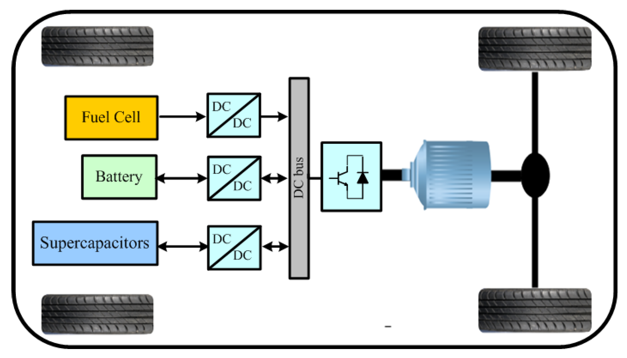
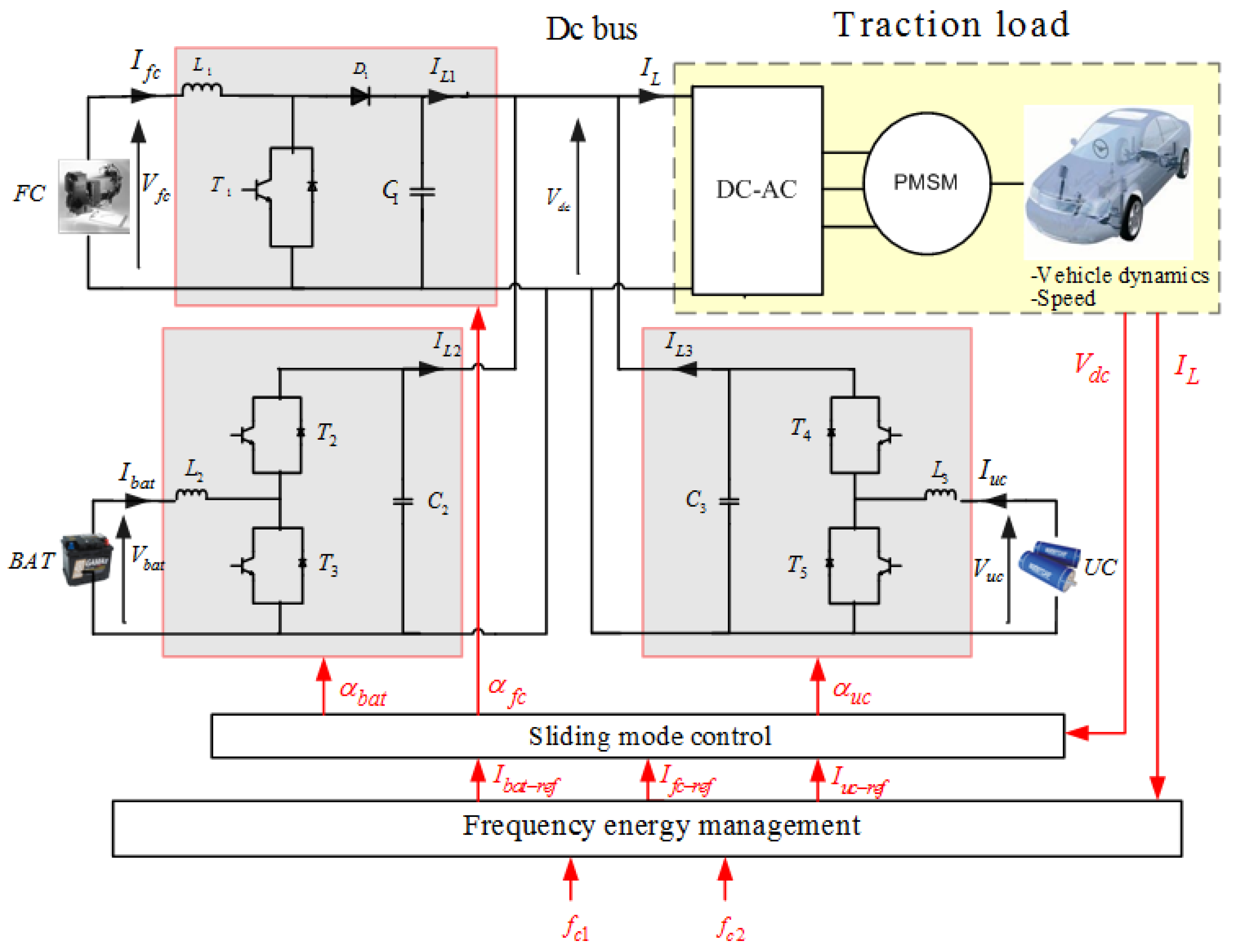
A variety of hybrid EV configurations has been proposed in the literature [30]. The selected topology is presented in Figure 1. The hybrid source consists of a PEMFC, a lithium ion (li-ion) battery and a pack of ultracapacitors coupled in parallel in a dc link and can supply together or separately the inverter of the traction motor through DC-DC converters. This configuration offers more flexibility in the control of the dc bus voltage that should be maintained constant during operation.
2.2. FC/BAT/UC Power Supply
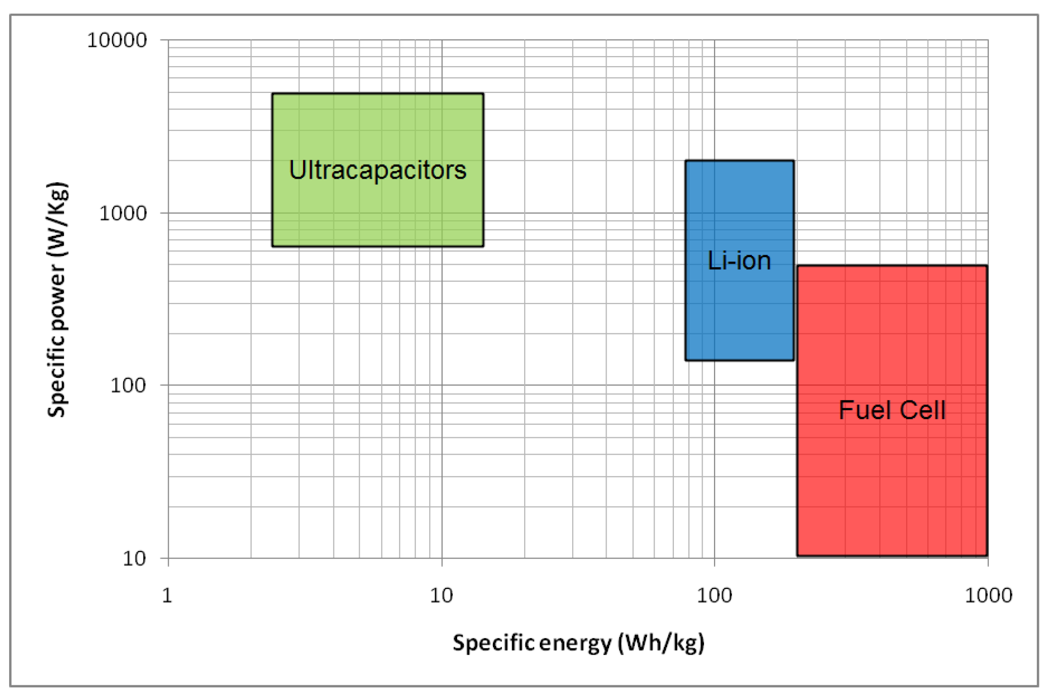
According to [31], hydrogen fuel cells can be classified as an ESS since they use stored energy—compressed hydrogen—to produce electricity. Indeed, electrical storage systems are usually compared through their technical and energetic characteristics via specific diagrams. Traditionally, the comparison criteria are represented in the form of a Ragone diagram [32] showing the specific power of a device according to its specific energy (Figure 2).
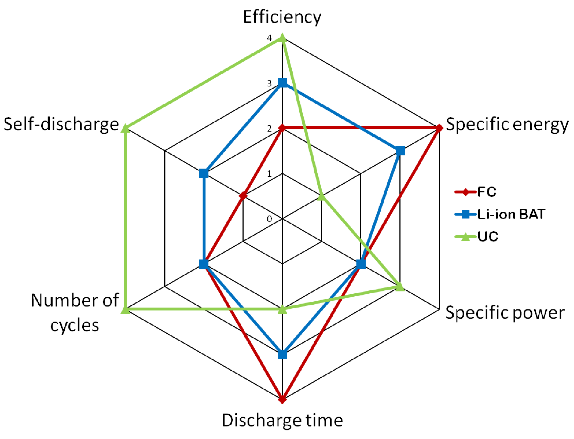
Furthermore, for a comparison through a larger number of aspects, which are also crucial in the evaluation of electric source performance such as life time number of cycles, energetic efficiency, discharge time and auto-discharge rate, spider diagrams can regroup all of these criteria into one chart [33]. Based on Table 1, the spider diagram of the FC/BAT/UC power source is given in Figure 3.
As it can be noticed, hydrogen fuel cells are characterized by the higher specific energy and a zero auto discharge rate. Other benefits include clean and quiet generation process, easy scaling and compact design [34]. On the other side, its long start up time—a range of minutes—[35] and low specific power significantly limit its performance in fast dynamic applications.
Lithium ion batteries have interesting advantages compared to older technologies—lead acid and nickel metal—including wide range of operating temperature, low self-discharge rate and higher specific energy [36]. However, despite the considerable advances on lithium cell technology, fast and frequent changes on its charge/discharge current rate as well as the amount and number of rest in a discharged state still present the major battery aging factors [37].
Supercapacitors, with much higher power density, longer life time, shorter charging and discharging time and much lower energy density than batteries [38], are most adapted to handle sudden transients on the time scale of several seconds. In fact, integrating supercapacitors in the hybrid power source leads to improving the vehicle dynamic and permits the downsizing of the battery pack resulting in cost and weight savings [39].
3. Modeling
3.1. Fuel Cell
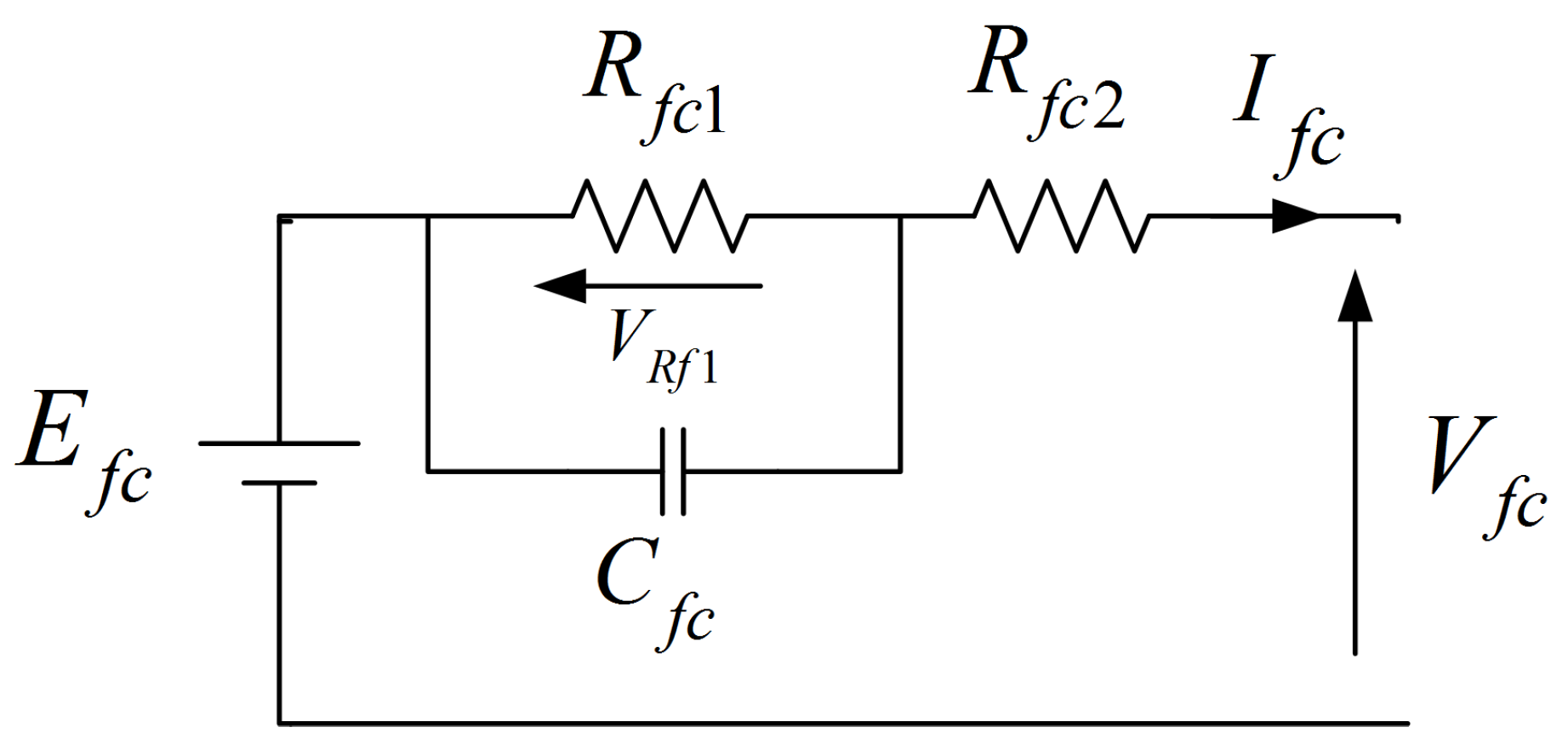
Depending on the purpose and the accuracy required, a variety of models have been developed for hydrogen fuel cells [43]. The FC used in this work is a PEMFC Nexa Ballard 1.2 kW/24 V. To reproduce its dynamic and energetic characteristics, an electric equivalent circuit based model is employed (Figure 4) [44].
The mathematical model of the fuel cell is provided in Equation (1)
An unidirectional boost converter, shown in Section 3.4, is employed to transfer the energy from the fuel cell to the power inverter as well as to adapt its voltage to the dc bus voltage. The fuel cell model parameters are given in Table 2.
3.2. Li-Ion Battery
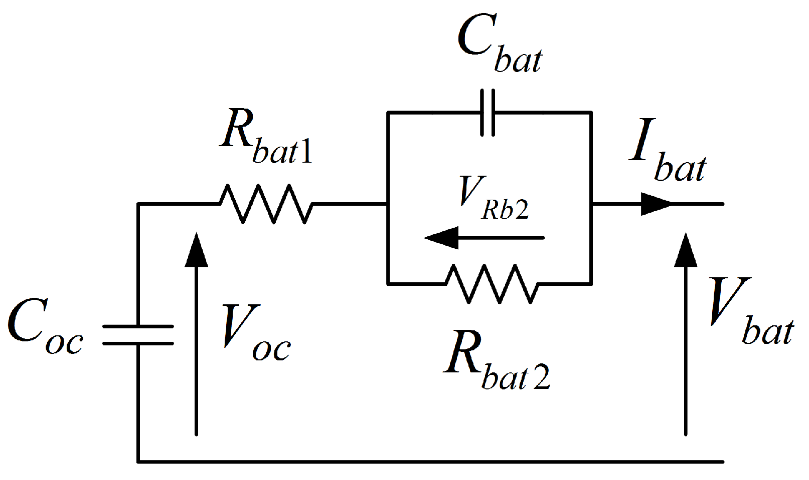
In EV applications, electric models are the most adapted to describe battery dynamic and to predict its SOC in real time operation [45]. A lithium iron phosphate (LiFePO) battery 12 V/40 Ah is employed in this study. Its equivalent circuit [46] is illustrated in Figure 5.
In the considered model, a capacity is used instead of constant voltage of typical Thevenin models, it leads to reproduce charge and discharge behaviour of the battery. represents the internal resistance of the battery and parallel highlights the rest time effect on the battery dynamic. The values of the model parameters are given in Table 3.
The state of charge of the battery is expressed in Equation (3)
Batteries degradation essentially depends on the state of charge range and also on the current variation. High current values, mainly during recharging, severely reduces the batteries lifetime. Therefore, as specified in [47], the battery degradation factor is calculated as follows:
with
and
where is the battery nominal current.
A buck boost converter is used to couple the battery to the dc bus. It allows to transfer the energy flow from the battery to the dc bus in discharge mode and from the dc bus to the battery in charge mode.
3.3. Ultracapacitors
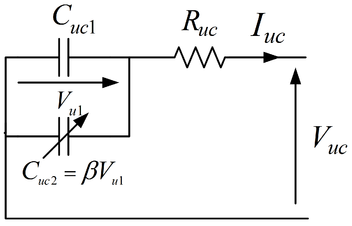
To form the supercapacitor pack, 10 series elements of the Maxwell technology BOOSTCAP 3000 F/2.7 V are used. The equivalent circuit of the module is presented in Figure 6.
The model includes an internal resistance and a branch of two parallel capacitances, is constant and varies linearly with the UC pack voltage [48]. The values of the model parameters are given in Table 4.
The mathematical model of the UC bank is given in Equation (5):
where is the voltage of the capacitance .
The ultracapacitor state of charge is illustrated in Equation (6):
where is the maximal voltage of the ultracapacitors.
A buck boost converter is used as interface between the pack of supercapacitors and the dc link.
3.4. Traction Load and Drive Environment
During operation, the electric drive train (motor, inverter and transmission schematized in Figure 7) draws a total current from the dc link. Assuming that the dc bus voltage is kept constant during operation and that the inverter efficiency is 80%, the load current can be obtained from the vehicle characteristics and the drive cycle using Equation (7):
where v, , , , M, , and g represent the vehicle speed, the air density, the aerodynamic drag coefficient, the vehicle frontal surface, the vehicle mass, the rolling resistance coefficient and the gravitational acceleration constant respectively.
4. Strategy of the Energy Management
4.1. Filtering-Based Energy Management Strategy
The filtering-based strategy of energy management allows to define the part of mission of each source according to its frequency and energetic specifications. To create a relation between the energy flow dynamics and the storage technology, specific frequency [49] is introduced and given as the ratio between the power density and the energy density .
Indeed, using Equation (8), the elements of the Ragone diagram can be reported in a frequency plane giving the range of frequencies allowed by each device.
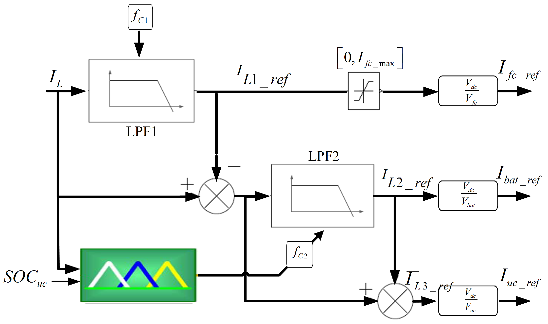
The proposed EMS is detailed in Figure 8. The idea is to decompose the total load current , equivalently, the load power, into three frequency components each component will be assigned to the appropriate source as a current reference. For this end, two low-pass filters with two different cut-off frequencies (,) are used. The first is fed with the load current and leads to generate the lower frequency harmonics that will be assigned to the fuel cell. While the second is fed with the difference between the load current and the fuel cell component and allows to generate the intermediate load content that will be sent to the battery. The remaining part of the demanded power representing, consequently, the higher dynamic component , will be assigned to the ultracapacitors. The expressions of the output current references are given in Equation (9)
Owing to the fact that the power split is highly influenced by the driving conditions (acceleration/deceleration, start-up/stop, changeable road slope), the separation frequencies should be updated with the load variation to prevent the over use or the over charge of one of the sources against other.
4.2. Auto Adaptation of the Frequency of Separation
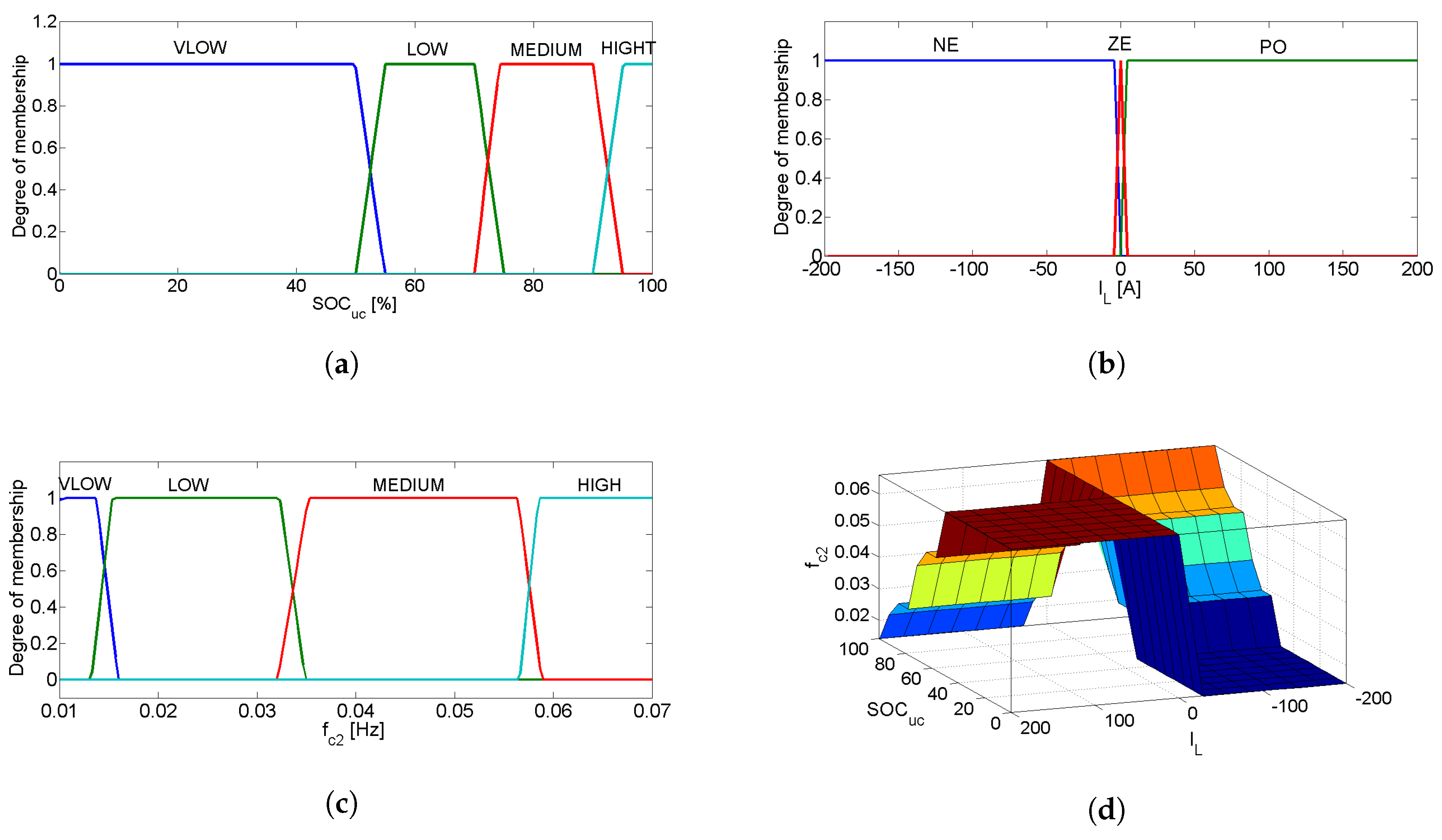
The cut-off frequency is set constant in the considered application, its value is chosen according to Equation (8) and leads to minimizing the fuel cell current fluctuations and then the cells degradation. With regard to , this parameter is adapted to the request using a Mamdani Fuzzy Logic System (FLS). The input variables of the FLS are the ultracapacitor state of charge and the load current (the battery SOC variation is very low compared to the UC one) and the output variable is the splitting frequency .
The main objective of the FLS is the optimization of the UC use in order to:
- Ensure a reasonable range of energy in the UC bank () [25].
- Relieve the strain on the battery by reducing its current slope.
- Stabilize the dc bus voltage at the desired reference V.
The fuzzification is carried out using trapezoidal membership functions. The variable has four membership functions classified as very low (VLOW), LOW, MEDIUM and HIGH (Figure 9a). The membership functions for are negative (NE), positive (PO) and zero (ZE) (Figure 9b) and the membership functions for are VLOW, LOW, MEDIUM and HIGH (Figure 9c).
A Min-Max fuzzy inference and a centroid defuzzification are used in this paper.
During start up and acceleration ( is PO), a maximum of energy should be extracted from the UCs when its SOC is HIGH so should be decreased to enlarge the power mission of the supercapacitors and reduce the battery one. If decreases, should increase to avoid the over use (deep discharging) of the ultra-capacitors.
During braking or deceleration ( is NE), if is VLOW, the higher part of regenerative energy should be recovered by the UC pack ( is VLOW) and when the state of charge increases the splitting frequency should increase. This procedure avoids deep discharging and overcharging of the UC module.
5. Sliding Mode Control
5.1. Principle of Operation
An SMC technique is adopted to control the voltage and the currents of considered hybrid source. Its role is to regulate the dc bus voltage to the desired reference as well as to assign the current references, generated from the EMS block, to the sources. This technique offers the advantage to design robust controllers for complex and non-linear dynamic applications and represents a low sensitivity to the plant parameter variations and disturbances [50]. In general, three principle conditions should be followed to synthesize a sliding mode-based controller:
- The attraction condition
- The existence condition
- The stability condition
5.1.1. The Attraction Condition
To force the controller to achieve the sliding surface S, the control signal u switches between two values and according to the sign of S. In this paper, u presents the duty cycle of the considered DC-DC converter (, or ) so the attraction condition will be:
5.1.2. The Existence Condition
The existence condition of the SMC is summarized in Equation (11):
Otherwise .
Where is the sliding surface slope.
The fulfillment of this inequality ensures the existence of the sliding mode around the surface S.
5.1.3. The Stability Condition
The stability condition of the SMC is given in Equation (12)
where is the time taken by the system to reach the sliding surface.
5.2. Fuel Cell Current Control
The sliding surface defined to control the fuel cell current is illustrated in Equation (13) [44].
where is a positive constant and is the FC current setpoint. The stability of the controller is verified for any positive value of . The control signal of the fuel cell converter ensuring the convergence of the current to its reference is defined by Equation (14).
5.3. Battery Current Control
The sliding surface adopted to control the battery current is illustrated in Equation (15).
where is a positive constant and is the battery current reference. The stability condition is verified for any positive value of . The control signal that ensures the convergence of the battery current to its setpoint is given in Equation (16).
5.4. Current and Voltage Control of the Ultracapacitor Pack
The sliding surface used to control the bus voltage and the UC current is provided by Equation (17)
where , are two positive constants, is the supercapacitor current setpoint and is the dc bus voltage setpoint. The control signal that ensures the convergence of the current and the voltage to their references is given in Equation (18).
6. Simulation Results
To simulate the behaviour of the hybrid power source, the overall system is modelled in MATLAB®/Simulink® using the SimPowerSystems library. The used vehicle parameters are given in Table 6.
In order to validate the approach under various driving conditions (urban, extra urban, etc.), simulations are carried out for four different driving cycles. The first is the New European Driving Cycle (NEDC) and represents the typical usage of a vehicle in Europe including four repeated urban driving cycles (ECE-15) and one Extra-Urban Driving Cycle (EUDC). The second is the EPA New York City Cycle (NYCC), it simulates a low speed driving with frequent stops in US city areas. The third is the SC03 Supplemental Federal Test Procedure (SFTP). The last is the new Worldwide harmonized Light vehicles Test Procedure (WLTP) including three different sub-cycles: a low speed cycle, a medium speed cycle and a high speed cycle. The considered hybrid system is simulated using a small scale load (all of the driving cycles are divided by three).
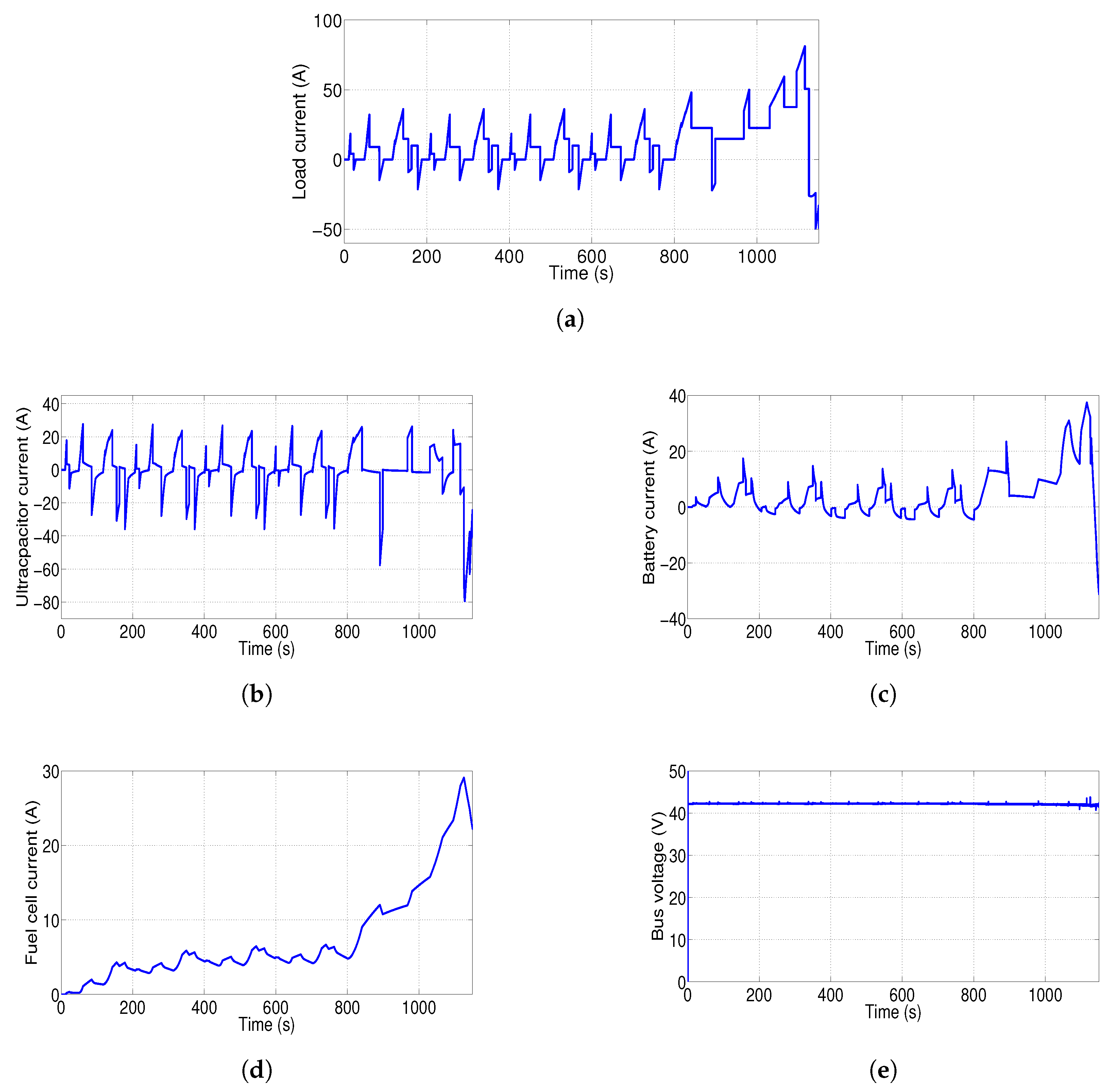
Figure 10 illustrates the ultracapacitor current, the battery current, the fuel cell current and the dc bus voltage given by applying the proposed adaptive filtering based EMS under the NEDC. The load current is shared between the sources while respecting the frequency domain specialization of each source. The supercapacitors provide the fast fluctuated content of the demand and maintain the dc bus voltage constant at the desired level of = 42 V. The li-ion battery supplies the smoothed component and the fuel cell provides the lower dynamic component (after several minutes of start-up).
To demonstrate the relevance of the proposed approach against traditional frequency management, simulations are carried out using a fixed separation frequency (three different values of are tested) and then using the proposed adaptive filtering-based EMS.
According to Equation (8) and the Ragone diagram (Figure 9b), the splitting frequency can vary between 0.007 Hz and 0.27 Hz and on the basis of preliminary analysis on the studied system this interval is delimited on (0.01 Hz; 0.07 Hz).
6.1. Fixed Energy Splitting
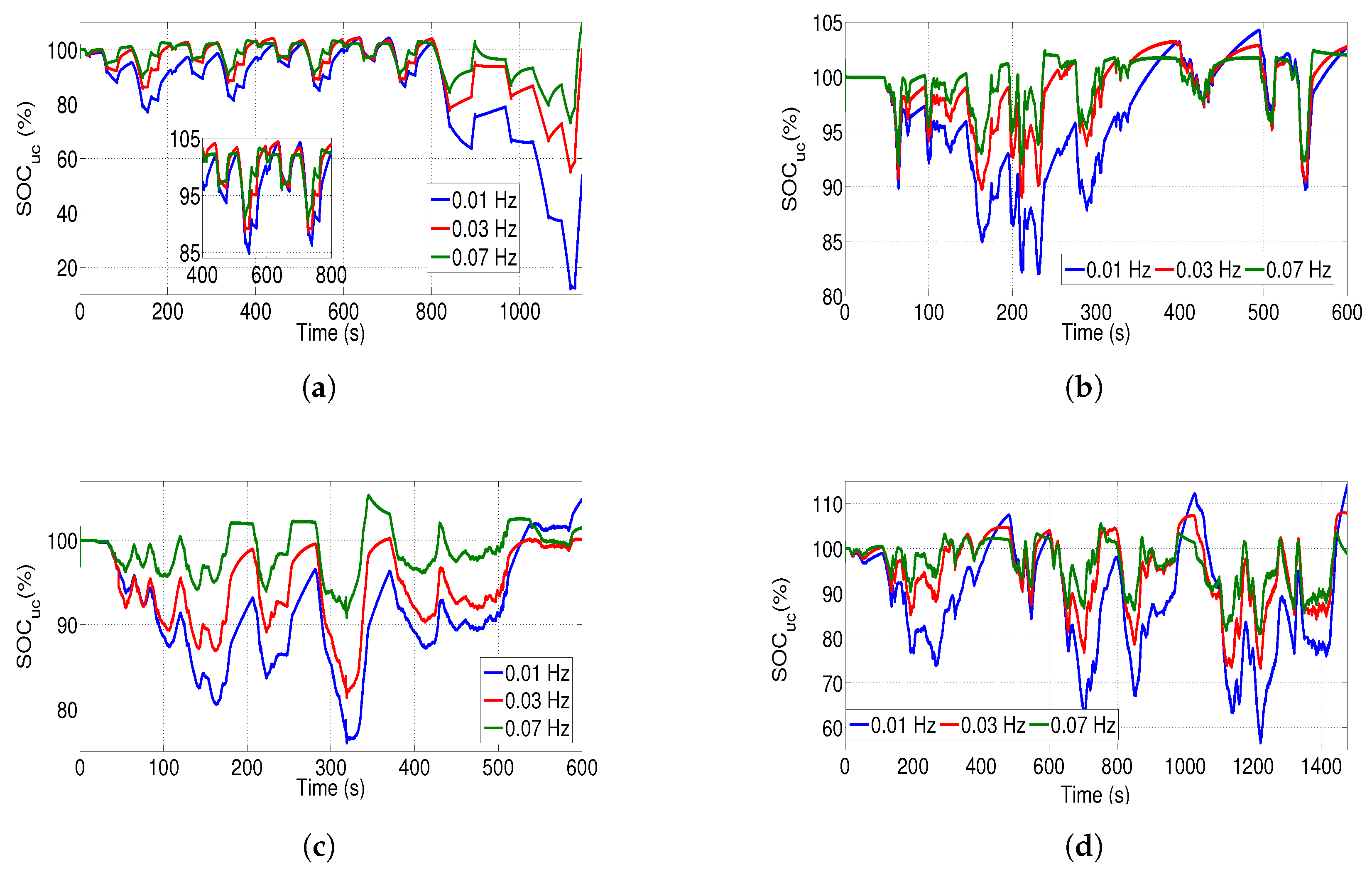
Figure 11 shows the evolution of ultracapacitor state of charge simulated for = 0.01 Hz, = 0.03 Hz and = 0.07 Hz under the NEDC, the NYCC, the SC03 and the WLTP respectively.
For the NEDC, a deep discharging is occurred ( = 10%) during the extra-urban driving cycle for = 0.01 Hz (over use of the UC pack) while an over charging is occurred ( = 105%) during the urban driving cycle for = 0.01 Hz and = 0.03 Hz.
For the other cycles, we note an overcharging for the three levels of . The UC sate of charge reaches 105% under the NYCC for = 0.01 Hz, 106% under the SC03 for = 0.07 Hz and 115% under the WLTP for = 0.01 Hz.
For the cut-off frequency = 0.03 Hz, the capacity limitation is respected under the SC03 and violated under the other cycles. A part of regenerative energy is lost during this unsafe operation mode and cannot be consequently recovered by the battery. We can conclude, then, that for a fixed splitting frequency, the ultracapcitors can be deeply discharged under some driving cycles and overcharged under others which limits the performance of fixed filtering-based EMS under real driving conditions.
6.2. Adaptive Energy Splitting
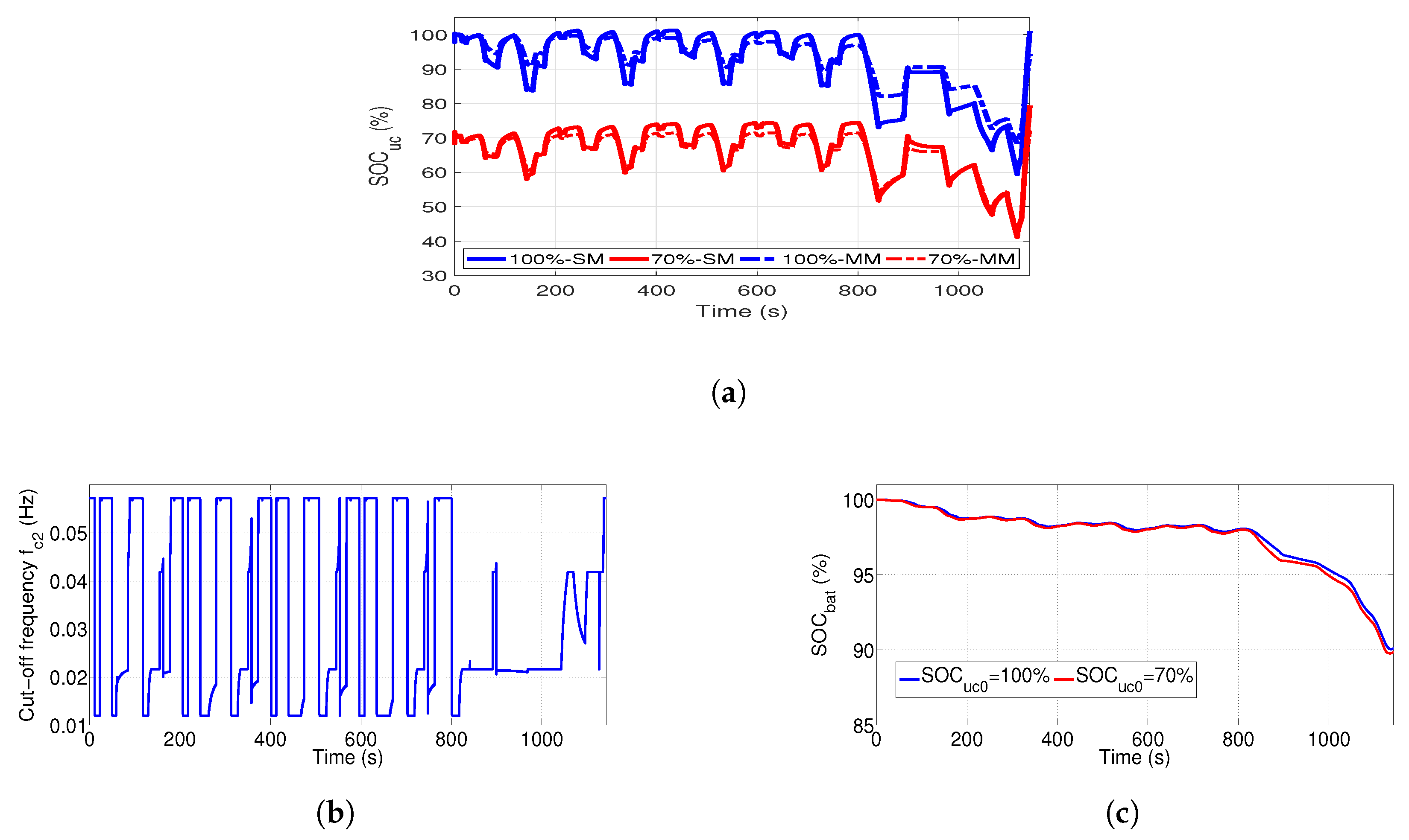
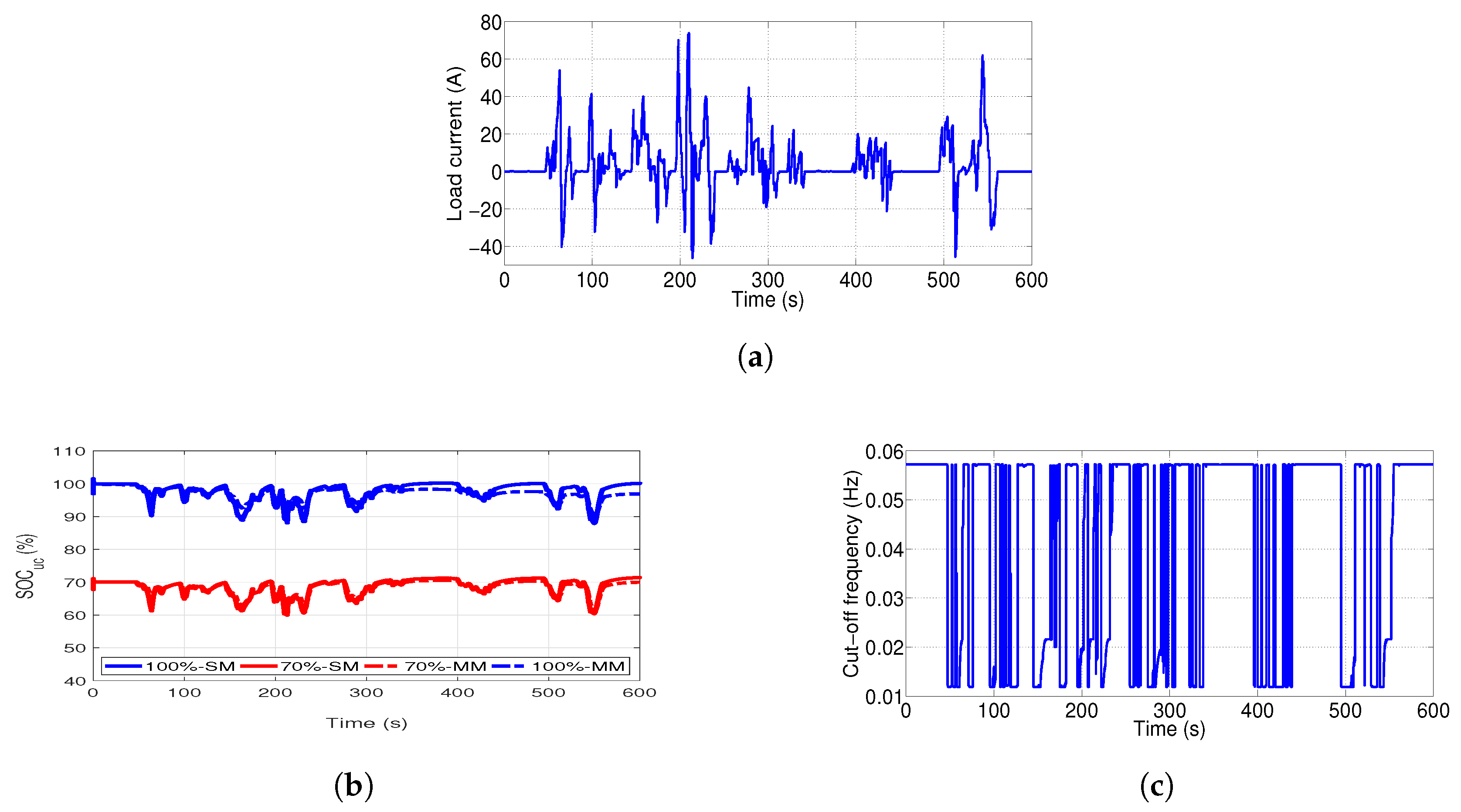
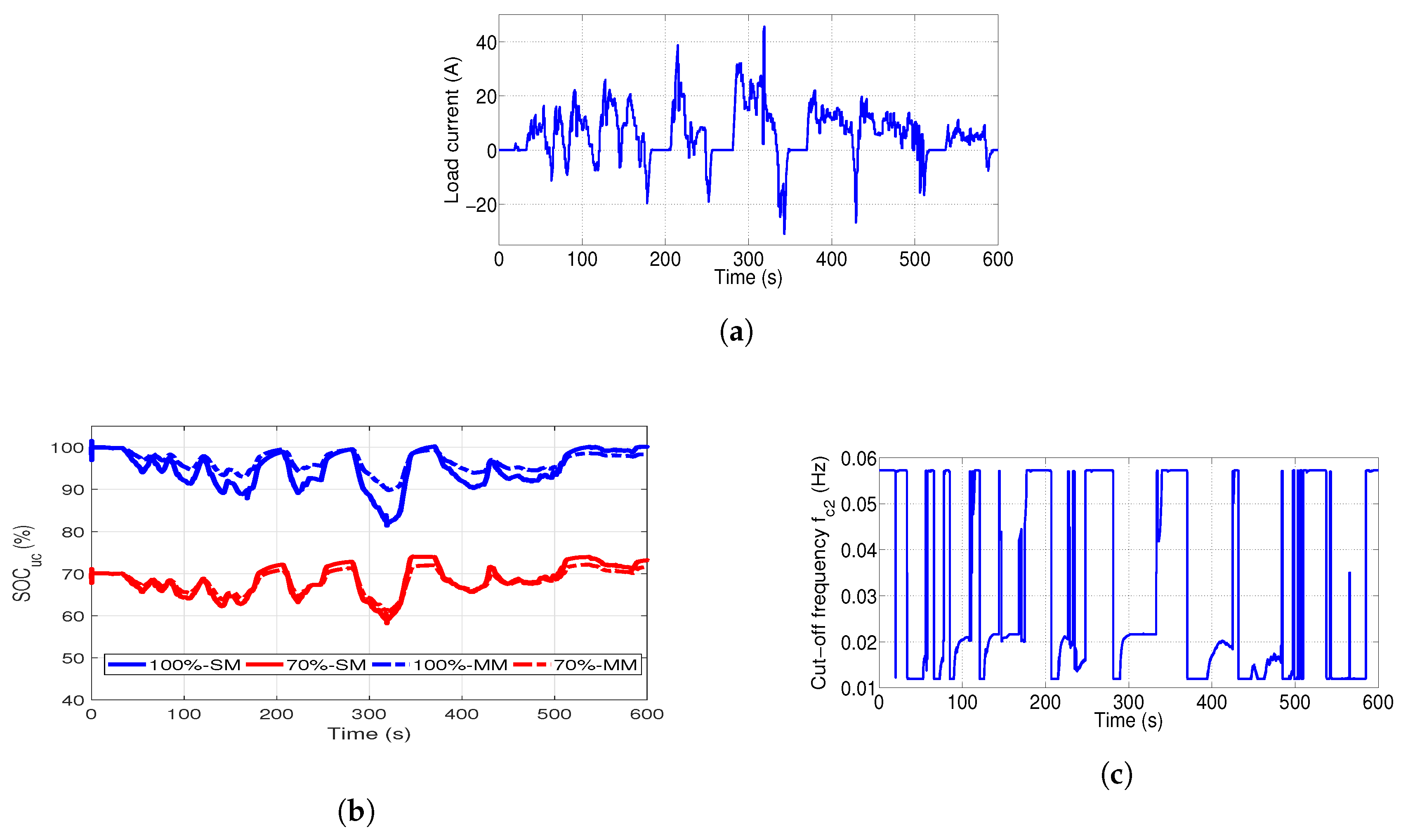
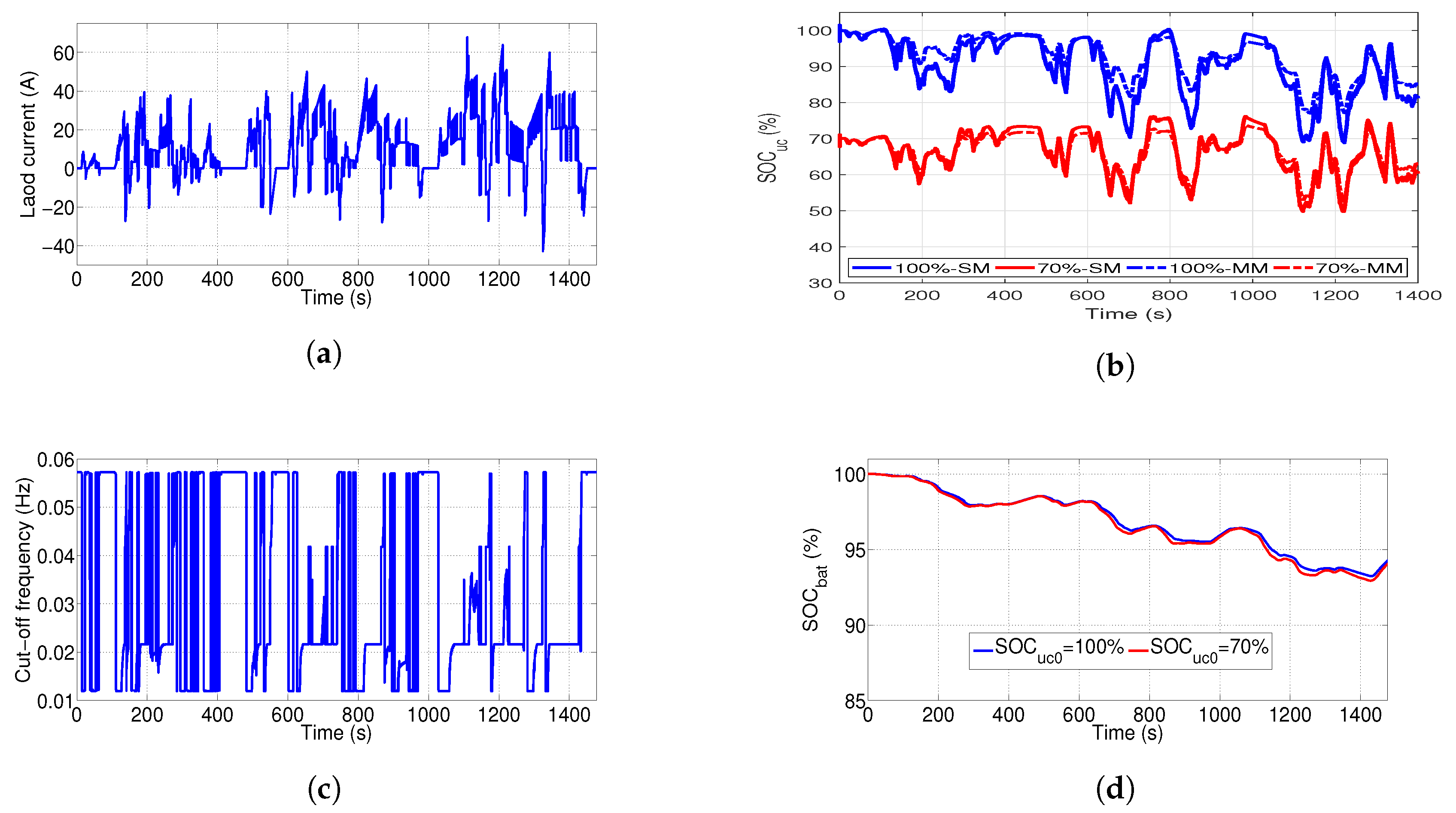
The simulation results obtained by applying the adaptive energy splitting are given in Figure 12, Figure 13, Figure 14 and Figure 15, for the simplified models (SM) developed in Section 3 and for the MATLAB®/SimPowerSystems® detailed models (MM).
The state of charge evolution is given, for the four driving cycles, when the UC module is fully charged ( = 100%) and when the UC module has an initial state of charge of 70% ( = 70%).
The effectiveness of the adaptive filtering approach is validated. The splitting frequencies are adapted, over the time, in accordance with the UC state of charge and the load demand. The resulting states of charge are kept within the admissible limits of 40% and 100% in all of the proposed tests even in harsh driving conditions (EUDC and WLTP) for both simulation models:
- Under the NEDCfor .for .
- Under the NYCCfor .for .
- Under the SC03for .for .
- Under the WLTPfor .for .
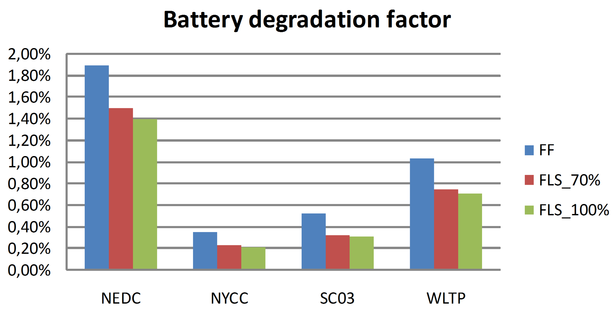
The degradation factor of the li-ion battery is calculated in (%) for 100 h of battery operation using fixed and adaptive splitting frequency (Figure 16). The results indicate an improvement by 0.5% in the battery longevity during the simulation period.
This value would be increased over the operation period of the battery. The performances of the proposed EMS are also confirmed through battery responses given in Figure 12c and Figure 15d. The battery states of charge given for the NEDC and the WLTP when show the same profiles as given for . Which means that for the same amount of the energy drawn from the battery, the UC pack gained 10% on its state of charge under the NEDC and 5% under the WLTP.
7. Conclusions
An adaptive-filtering-based EMS for a fuel cell hybrid electric vehicle powered by a PEMFC, a li-ion battery and a pack of ultracapacitors, is proposed in this paper. Basing on the frequency-separation of the mission power, the proposed EMS allows to efficiently explore the strength of the supercapacitors as a peak power source and the battery and fuel cell as perfect energy units.
Simulation results performed by applying the proposed adaptive filtering technique under different driving conditions have proven an effective energy sharing between the sources, submitted to different dynamic and energetic constraints. Higher dynamic content of the demand is routed into the UCs pack with a variable frequency, automatically adapted to the UC state of charge and the current demand. Which protects the system from unsafe operating mode and ensures a better performance and speed for the FCHEV.
Strain on the battery is significantly relieved when a maximum of energy is extracted from the UCs module within the admissible limits of state of charge leading to a battery longevity improvement. The energy consumption (hydrogen consumption) can be reduced when the totality of braking energy is recovered by the UCs when they present a low level of SOC or by the battery and the UCs when a reasonable range of energy is ensured in the UCs module or only by the battery when the UCs are in a fully charged state.
Thereby, durability and autonomy of the hybrid power source can be improved with minimal and low cost changes and a good trade off between performance and simplicity is achieved making possible on-line implementation of the proposed adaptive-filtering energy management strategy on board any hybrid electric vehicle.
Author Contributions
J.S. designed the system architecture and performed the simulations experiments; S.B.E. analyzed the data and verified the simulation results; M.B. and M.F.M. supervised the whole research procedure of this paper.
Funding
Research received no external fund.
Conflicts of Interest
The authors declare no conflict of interest.
References
- Erdinc, O.; Uzunoglu, M. Recent trends in PEM fuel cell-powered hybrid systems: Investigation of application areas, design architectures and energy management approaches. Renew. Sustain. Energy Rev. 2010, 14, 2874–2884. [Google Scholar] [CrossRef]
- Mekhilef, S.; Saidur, R.; Safari, A. Comparative study of different fuel cell technologies. Renew. Sustain. Energy Rev. 2012, 16, 981–989. [Google Scholar] [CrossRef]
- Huang, P.H.; Kuo, J.K.; Han, C.Y. Numerical investigation into slope-climbing capability of fuel cell hybrid scooter. Appl. Therm. Eng. 2017, 110, 921–930. [Google Scholar] [CrossRef]
- Fontela, P.; Soria, A.; Mielgo, J.; Sierra, J.F.; de Blas, J.; Gauchia, L.; Martínez, J.M. Airport electric vehicle powered by fuel cell. J. Power Source 2007, 169, 184–193. [Google Scholar] [CrossRef]
- Gao, D.; Jin, Z.; Zhang, J.; Li, J.; Ouyang, M. Comparative Study of Two Different Powertrains for a Fuel Cell Hybrid Bus. J. Power Source 2016, 319, 9–18. [Google Scholar] [CrossRef]
- Li, Q.; Yang, H.; Han, Y.; Li, M.; Chen, W. A state machine strategy based on droop control for an energy management system of PEMFC-battery-supercapacitor hybrid tramway. Int. J. Hydrog. Energy 2016, 41, 16148–16159. [Google Scholar] [CrossRef]
- Guida, D.; Minutillo, M. Design methodology for a PEM fuel cell power system in a more electrical aircraft. Appl. Energy 2017, 192, 446–456. [Google Scholar] [CrossRef]
- Chris, M.; Masrur, M.A. Vehicular Power Control Strategy and Energy Management. In Hybrid Electric Vehicles; Wiley-Blackwell: Hoboken, NJ, USA, 2017; Chapter 17; pp. 521–537. [Google Scholar]
- Wei, L. Energy Management Strategies for Hybrid Electric Vehicles. In Hybrid Electric Vehicle System Modeling and Control; Wiley-Blackwell: Hoboken, NJ, USA, 2017; Chapter 6; pp. 243–287. [Google Scholar] [Green Version]
- Prasanna, U.R.; Xuewei, P.; Rathore, A.K.; Rajashekara, K. Propulsion System Architecture and Power Conditioning Topologies for Fuel Cell Vehicles. IEEE Trans. Ind. Appl. 2015, 51, 640–650. [Google Scholar] [CrossRef]
- Mebarki, N.; Rekioua, T.; Mokrani, Z.; Rekioua, D.; Bacha, S. PEM fuel cell/battery storage system supplying electric vehicle. Int. J. Hydrog. Energy 2016, 41, 20993–21005. [Google Scholar] [CrossRef]
- Hu, Z.; Li, J.; Xu, L.; Song, Z.; Fang, C.; Ouyang, M.; Dou, G.; Kou, G. Multi-objective energy management optimization and parameter sizing for proton exchange membrane hybrid fuel cell vehicles. Energy Convers. Manag. 2016, 129, 108–121. [Google Scholar] [CrossRef]
- Erjavec, J. Hybrid, Electric, and Fuel-Cell Vehicles; Delmer Cengage Learning: Boston, MA, USA, 2013. [Google Scholar]
- Thounthong, P.; Chunkag, V.; Sethakul, P.; Davat, B.; Hinaje, M. Comparative Study of Fuel-Cell Vehicle Hybridization with Battery or Supercapacitor Storage Device. IEEE Trans. Veh. Technol. 2009, 58, 3892–3904. [Google Scholar] [CrossRef]
- Rezzak, D.; Boudjerda, N. Management and control strategy of a hybrid energy source fuel cell/supercapacitor in electric vehicles. Int. Trans. Electr. Energy Syst. 2017, 27, e2308. [Google Scholar] [CrossRef]
- Azib, T.; Larouci, C.; Chaibet, A.; Boukhnifer, M. Management and control strategy of a hybrid energy source fuel cell/supercapacitor in electric vehicles. Int. Trans. Electr. Electron. Eng. 2014, 9, 548–554. [Google Scholar] [CrossRef]
- Rajabzadeh, M.; Bathaee, S.M.T.; Golkar, M.A. Dynamic modeling and nonlinear control of fuel cell vehicles with different hybrid power sources. Int. J. Hydrog. Energy 2016, 41, 3185–3198. [Google Scholar] [CrossRef]
- Boltersdorf, J.; Delpa, S.A.; Yan, J.; Cao, B.; P.Zheng, J.; Jow, T.R.; A.Reada, J. Electrochemical performance of lithium-ion capacitors evaluated under high temperature and high voltage stress using redox stable electrolytes and additives. J. Power Source 2018, 373, 20–30. [Google Scholar] [CrossRef]
- Yana, J.; Cao, W.; Zheng, J. Constructing High Energy and Power Densities Li-Ion Capacitors Using Li Thin Film for Pre-Lithiation. J. Electrochem. Soc. 2017, 164, 2164–2170. [Google Scholar] [CrossRef]
- Thounthong, P.; Raël, S.; Davat, B. Energy management of fuel cell/battery/supercapacitor hybrid power source for vehicle applications. J. Power Source 2009, 193, 376–385. [Google Scholar] [CrossRef]
- Li, M.; Xu, H.; Li, W.; Liu, Y.; Li, F.; Hu, Y.; Liu, L. The structure and control method of hybrid power source for electric vehicle. Energy 2016, 112, 1273–1285. [Google Scholar] [CrossRef]
- Murphey, Y.L.; Park, J.; Chen, Z.; Kuang, M.L.; Masrur, M.A.; Phillips, A.M. Intelligent Hybrid Vehicle Power Control—Part I: Machine Learning of Optimal Vehicle Power. IEEE Trans. Veh. Technol. 2012, 61, 3519–3530. [Google Scholar] [CrossRef]
- Neffati, A.; Guemri, M.; Caux, S.; Fadel, M. Energy management strategies for multi source systems. Electr. Power Syst. Res. 2013, 102, 42–49. [Google Scholar] [CrossRef]
- Zhang, S.; Xiong, R.; Sun, F. Model predictive control for power management in a plug-in hybrid electric vehicle with a hybrid energy storage system. Appl. Energy 2017, 185, 1654–1662. [Google Scholar] [CrossRef]
- Herrera, V.; Milo, A.; Gaztanaga, H.; Etxeberria-Otadui, I.; Villarreal, I.; Camblong, H. Adaptive energy management strategy and optimal sizing applied on a battery-supercapacitor based tramway. Appl. Energy 2016, 169, 831–845. [Google Scholar] [CrossRef]
- Bizon, N. Real-time optimization strategy for fuel cell hybrid power sources with loadfollowing control of the fuel or air flow. Energy Convers. Manag. 2018, 157, 13–27. [Google Scholar] [CrossRef]
- Sulaiman, N.; Hannan, M.A.; Mohamed, A.; Majlan, E.H.; Daud, W.R.W. A review on energy management system for fuel cell hybrid electric vehicle: Issues and challenges. Renew. Sustain. Energy Rev. 2015, 52, 802–814. [Google Scholar] [CrossRef]
- Sandoval, C.; Alvarado, V.M.; Carmona, J.C.; Lopez, G.L.; Gomez-Aguilar, J.F. Energy management control strategy to improve the FC/SC dynamic behavior on hybrid electric vehicles: A frequency based distribution. Renew. Energy 2017, 105, 407–418. [Google Scholar] [CrossRef]
- Snoussi, J.; Elghali, S.B.; Outbib, R.; Mimouni, M.F. Sliding mode control for frequency-based energy management strategy of hybrid Storage System in vehicular application. In International Symposium on Power Electronics, Electrical Drives, Automation and Motion (SPEEDAM); IEEE: Piscataway, NJ, USA, 2016; pp. 1109–1114. [Google Scholar]
- Zimmermann, T.; Keil, P.; Hofmann, M.; Horsche, M.F.; Pichlmaier, S.; Jossen, A. Review of system topologies for hybrid electrical energy storage systems. J. Energy Storage 2016, 8, 78–90. [Google Scholar] [CrossRef]
- Luo, X.; Wang, J.; Dooner, M.; Clarke, J. Overview of current development in electrical energy storage technologies and the application potential in power system operation. Appl. Energy 2014, 137, 511–536. [Google Scholar] [CrossRef]
- Christen, T.; Carlen, M.W. Theory of Ragone plots. J. Power Source 2000, 91, 210–216. [Google Scholar] [CrossRef]
- Devillers, N. Caracterisation Et Modelisation De Composants De Stockage Electrochimique Et Electrostatique; Universite de Franche-Comte: Besancon, France, 2012. [Google Scholar]
- Vasquez, T.L.O. Fuel Cell Research Trends; Nova Science Publishers: Hauppauge, NY, USA, 2007. [Google Scholar]
- Whittingham, M.S.; Savinell, R.F.; Zawodzinski, T. Introduction: Batteries and Fuel Cells. Chem. Rev. 2004, 104, 4243–4244. [Google Scholar] [CrossRef] [PubMed] [Green Version]
- Kim, M.Y.; Kim, C.H.; Kim, J.H.; Moon, G.W. A Chain Structure of Switched Capacitor for Improved Cell Balancing Speed of Lithium-Ion Batteries. IEEE Trans. Ind. Electron. 2014, 61, 3989–3999. [Google Scholar] [CrossRef]
- Dudezert, C.; Reynier, Y.; Duffault, J.M.; Franger, S. Fatigue damage approach applied to Li-ion batteries ageing characterization. Mater. Sci. Eng. B 2016, 213, 177–189. [Google Scholar] [CrossRef]
- Libich, J.; Maca, J.; Vondrak, J.; Cech, O.; Sedlarikova, M. Supercapacitors: Properties and applications. J. Energy Storage 2018, 17, 224–227. [Google Scholar] [CrossRef]
- Bubna, P.; Advani, S.G.; Prasad, A.K. Integration of batteries with ultracapacitors for a fuel cell hybrid transit bus. J. Power Source 2012, 199, 360–366. [Google Scholar] [CrossRef]
- Song, Z.; Li, J.; Hou, J.; Hofmann, H.; Ouyang, M.; Du, J. The battery-supercapacitor hybrid energy storage system in electric vehicle applications: A case study. Energy 2018, 154, 433–441. [Google Scholar] [CrossRef]
- Marzougui, H.; Amari, M.; Kadri, A.; Bacha, F.; Ghouili, J. Integration of batteries with ultracapacitors for a fuel cell hybrid transit bus. Int. J. Hydrog. Energy 2017, 42, 8857–8869. [Google Scholar] [CrossRef]
- Pablo, G.; Juan, P.; Torreglosa, L.M.F.F.J. Control strategies for high-power electric vehicles powered by hydrogen fuel cell, battery and supercapacitor. Expert Syst. Appl. 2013, 40, 4791–4804. [Google Scholar]
- Saadi, A.; Becherif, M.; Hissel, D.; Ramadan, H.S. Dynamic modeling and experimental analysis of PEMFCs: A comparative study. Int. J. Hydrog. Energy 2017, 42, 1544–1557. [Google Scholar] [CrossRef]
- Maker, H. Optimisation Et Gestion D’Energie Pour Un Systeme Hybride: Association Pile a Combustible Et Supercondensateurs; Belfort Montbeliard University: Belfort, France, 2008. [Google Scholar]
- He, H.; Xiong, R.; Guo, H.; Li, S. Comparison study on the battery models used for the energy management of batteries in electric vehicles. Energy Convers. Manag. 2012, 64, 113–121. [Google Scholar] [CrossRef]
- Lim, K.; Bastawrous, H.A.; Duong, V.H.; See, K.W.; Zhang, P.; Dou, S.X. Fading Kalman filter-based real-time state of charge estimation in LiFePO4 battery-powered electric vehicles. Appl. Energy 2016, 169, 40–48. [Google Scholar] [CrossRef]
- Amaya, E.G.; Chiacchiarini, H.; Angelo, C.D.; Asensio, M. The Energy Management Strategy of FC/Battery Vehicles Winner of the 2017 IEEE VTS Motor Vehicles Challenge. In Proceedings of the 2017 IEEE Vehicle Power and Propulsion Conference (VPPC), Belfort, France, 11–14 December 2017; pp. 1–6. [Google Scholar]
- Camara, M.B.; Gualous, H.; Gustin, F.; Berthon, A.; Dakyo, B. DC/DC Converter Design for Supercapacitor and Battery Power Management in Hybrid Vehicle Applications—Polynomial Control Strategy. IEEE Trans. Ind. Electron. 2010, 57, 587–597. [Google Scholar] [CrossRef]
- Akli, C.R. Conception Systemique D’Une Locomotive Hybride Autonome: Application a La Locomotive Hybride De Demonstration Et D’Investigations Energetique LhyDIE Developpee Par La SNCF; INP Toulouse: Toulouse, France, 2008. [Google Scholar]
- Utkin, V. Control Systems, Robotics and Automation XIII; Eolss Publishers: Paris, France, 2009. [Google Scholar]
Figure 1.
Fuel cell hybrid electric vehicle configuration.

Figure 2.
Ragone diagram.

Figure 3.
Spider diagram of the hybrid power source.

Figure 4.
Fuel cell model.

Figure 5.
Battery model.

Figure 6.
Ultracapacitor model.

Figure 7.
Traction system of the Fuel Cell Hybrid Electric Vehicle.

Figure 8.
Filtering-based energy management.

Figure 9.
Fuzzy logic system: (a) membership functions; (b) membership functions; (c) membership functions; (d) fuzzy rules surface.
Figure 9.
Fuzzy logic system: (a) membership functions; (b) membership functions; (c) membership functions; (d) fuzzy rules surface.

Figure 10.
Characteristics of the sources obtained by applying the frequency based Strategy of Energy Management (EMS): (a) The total load current ; (b) the ultracapacitor load current ; (c) The battery load current ; (d) The fuel cell load current ; (e) The dc bus voltage .
Figure 10.
Characteristics of the sources obtained by applying the frequency based Strategy of Energy Management (EMS): (a) The total load current ; (b) the ultracapacitor load current ; (c) The battery load current ; (d) The fuel cell load current ; (e) The dc bus voltage .

Figure 11.
State of charge of the ultracapacitor pack for , and : (a) Extra-Urban Driving Cycle (EUDC); (b) New York City Cycle (NYCC); (c) SC03; (d) Worldwide harmonized Light vehicles Test Procedure (WLTP).
Figure 11.
State of charge of the ultracapacitor pack for , and : (a) Extra-Urban Driving Cycle (EUDC); (b) New York City Cycle (NYCC); (c) SC03; (d) Worldwide harmonized Light vehicles Test Procedure (WLTP).

Figure 12.
Simulation results obtained by applying the adaptive filtering based EMS for the New European Driving Cycle (NEDC): (a) Ultracapacitors state of charge; (b) Cut-off frequency ; (c) Battery state of charge.
Figure 12.
Simulation results obtained by applying the adaptive filtering based EMS for the New European Driving Cycle (NEDC): (a) Ultracapacitors state of charge; (b) Cut-off frequency ; (c) Battery state of charge.

Figure 13.
Simulation results obtained by applying the adaptive filtering based EMS for the NYCC: (a) Load current; (b) Ultracapacitors state of charge; (c) Cut-off frequency .
Figure 13.
Simulation results obtained by applying the adaptive filtering based EMS for the NYCC: (a) Load current; (b) Ultracapacitors state of charge; (c) Cut-off frequency .

Figure 14.
Simulation results obtained by applying the adaptive filtering based EMS for the SC03: (a) Load current; (b) Ultracapacitors state of charge; (c) Cut-off frequency .
Figure 14.
Simulation results obtained by applying the adaptive filtering based EMS for the SC03: (a) Load current; (b) Ultracapacitors state of charge; (c) Cut-off frequency .

Figure 15.
Simulation results obtained by applying the adaptive filtering based EMS for the WLTP: (a) Load current; (b) Ultracapacitor state of charge; (c) Cut-off frequency ; (d) Battery state of charge.
Figure 15.
Simulation results obtained by applying the adaptive filtering based EMS for the WLTP: (a) Load current; (b) Ultracapacitor state of charge; (c) Cut-off frequency ; (d) Battery state of charge.

Figure 16.
Battery degradation factor.


Table 1.
Evaluation scale for electric storage system characteristics.
| Level | 1 | 2 | 3 | 4 |
|---|---|---|---|---|
| Efficiency (%) | 20–40 | 40–70 | 70–90 | 90–98 |
| Specific enegy (Wh·kg) | <20 | 20–100 | 100–500 | >500 |
| Specific power (W·kg) | 0–150 | 150–1500 | 1500–5000 | >5000 |
| Discharge time | ms-min | ms-1 h | min-h | s-days |
| Number of cycles | <1000 | 1000–20,000 | 20,000–50,000 | >50,000 |
| Self-discharge (%) | <0.1 | 0.1–1 | 1–10 | 10–40 |
Table 2.
Parameters of fuel cell model.
| Parameter | Value |
|---|---|
| V | |
| F |
Table 3.
Parameters of li-ion battery model.
| Parameter | Value |
|---|---|
| 2.3138 × 10 F | |
| F | |
Table 4.
Parameters of ultracapacitor pack model.
| Parameter | Value |
|---|---|
| 256 F | |
| m | |
| F/V |
Table 5.
Fuzzy logic rules.
| NE | ZE | PO | ||
|---|---|---|---|---|
| VLOW | VLOW | HIGH | HIGH | |
| LOW | LOW | HIGH | MEDIUM | |
| MEDIUM | MEDIUM | HIGH | LOW | |
| HIGH | HIGH | HIGH | VLOW | |
Table 6.
Parameters of the Fuel Cell Hybrid Electric Vehicle (FCHEV).
| Parameter | Value |
|---|---|
| 1.223 Kg/m | |
| 2 m | |
| M | 1000 kg |
| 0.35 | |
| 0.01 | |
| g | 9.81 N/Kg |
© 2018 by the authors. Licensee MDPI, Basel, Switzerland. This article is an open access article distributed under the terms and conditions of the Creative Commons Attribution (CC BY) license (http://creativecommons.org/licenses/by/4.0/).
Share and Cite
MDPI and ACS Style
Snoussi, J.; Ben Elghali, S.; Benbouzid, M.; Mimouni, M.F. Auto-Adaptive Filtering-Based Energy Management Strategy for Fuel Cell Hybrid Electric Vehicles. Energies 2018, 11, 2118. https://doi.org/10.3390/en11082118
AMA Style
Snoussi J, Ben Elghali S, Benbouzid M, Mimouni MF. Auto-Adaptive Filtering-Based Energy Management Strategy for Fuel Cell Hybrid Electric Vehicles. Energies. 2018; 11(8):2118. https://doi.org/10.3390/en11082118
Chicago/Turabian StyleSnoussi, Jamila, Seifeddine Ben Elghali, Mohamed Benbouzid, and Mohamed Faouzi Mimouni. 2018. "Auto-Adaptive Filtering-Based Energy Management Strategy for Fuel Cell Hybrid Electric Vehicles" Energies 11, no. 8: 2118. https://doi.org/10.3390/en11082118
Note that from the first issue of 2016, this journal uses article numbers instead of page numbers. See further details here.