Article

Design and Prototyping Medium-Frequency Transformers Featuring a Nanocrystalline Core for DC–DC Converters

by
Dante Ruiz-Robles
1,*,
Vicente Venegas-Rebollar
1,
Adolfo Anaya-Ruiz
1,
Edgar L. Moreno-Goytia
1 and
Juan R. Rodríguez-Rodríguez
2
1
Graduate Program and Research in Electrical Engineering (PGIIE), Instituto Tecnológico de Morelia, Morelia 58120, Mexico
2
Energía Eléctrica, Universidad Nacional Autónoma de México, Ciudad de México 04510, Mexico
*
Author to whom correspondence should be addressed.
Energies 2018, 11(8), 2081; https://doi.org/10.3390/en11082081
Submission received: 16 July 2018 / Revised: 29 July 2018 / Accepted: 1 August 2018 / Published: 10 August 2018

Abstract

:
Medium frequency transformers (MFTs) are a key component of DC–DC dual active bridge (DAB)-type converters. These technologies are becoming a quintessential part of renewable energy solutions, such as photovoltaic systems and wind energy power plants, as well as in modern power grid interfaces functioning as solid-state transformers in smart-grid environments. The weight and physical dimensions of an MFT are key data for the design of these devices. The size of an MFT is reduced by increasing its operating frequency. This reduction implicates higher power density through the transformer windings, as well as other design requirements distinct to those used for conventional 60/50 Hz transformers; therefore, new MFT design procedures are needed. This paper introduces a novel methodology for designing MFTs, using nanocrystalline cores, and tests it using an MFT–DAB lab prototype. Different to other MFT design procedures, this new design approach uses a modified version of the area-product technique, which consists of smartly modifying the core losses computation, and includes nanocrystalline cores. The core losses computation is supported by a full analysis of the dispersion inductance. For purposes of validation, a model MFT connected to a DAB converter is simulated in Matlab-Simulink (The MathWorks, v2014a, Mexico City, Mexico). In addition, a MFT–DAB lab prototype (1 kVA at 5 kHz) is implemented to experimentally probe further the validity of the methodology just proposed. These results demonstrate that the analytic calculations results match those obtained from simulations and lab experiments. In all cases, the efficiency of the MFT is greater than 99%.

Graphical Abstract

1. Introduction

From the designer’s point of view, the requirement of high power density for medium frequency transformers (MFTs) is one key parameter in the process for the developing new DC–DC dual active bridge (DAB)-type converters [1,2]. Increasing the operating frequency reduces the physical dimensions of a transformer. As an immediate consequence, the power density through the windings increases [3,4,5]. Other factors influencing the power loss are the surface or skin effect [6] and the eddy-currents [7]. The parameters associated with power loss must be taken into consideration in the transformer design procedure [8]. The MFTs have a range of applications in DC–DC converters for smart networks [9], electric vehicles [10], wind power generators and plants [11], interfacing of photovoltaic systems [1], and solid state transformers [12,13].
Although MFTs have plenty of opportunities, their weak point with regards to further increasing the application of MFTs in today’s medium voltage grids are their design procedures. The design for this type of transformer has received little attention. This paper introduces a new MFT design procedure in the pursuit of filling that gap.
The main materials for transformer cores, such as silicon steel [14], ferrites [15], and amorphous materials [16], help to increase the density of magnetic flow (B). This density increment redounds to a reduction of the weight and physical dimensions of transformers, but at the expense of higher core losses and reduced efficiency [17]. A newcomer in this list are the nanocrystalline materials. These materials have high density of magnetic flow, low losses at medium frequencies (5 kHz), and good thermal properties [18]. Due to all these characteristics, nanocrystalline materials are an option to be considered for the design of MFTs.
The latest research efforts focused on building and designing MFTs focus on using distinct kinds of materials to increase the power density. It is well-known that in MFT designs, the greater the power density, the greater the flow density. In this context, flow densities lower than 0.6 T have been obtained using silicon steel and ferrita at medium frequency [19,20,21]. In contrast, higher flow densities can be obtained by using nanocrystalline materials. In [19], a MFT with nanocrystalline core is designed. Although the analysis and results are clearly justified, the latter are not experimentally validated using a DC–DC interface. However, not using DC–DC converters is a disadvantage, because the actual behaviour of the MFT cannot be obtained. In [14], Pei-Huang presents a 1 kHz/35 kW MFT design using a silicon steel core. The power density achieved is 2.96 kW/l. However, for an operation at 5 kHz, the core losses increase significantly, which derates efficiency. In addition, the flow density achieved, 0.5 T, is far lower than the one that can be obtained with nanocrystalline materials at such a frequency. From another point of view, in [20], Krishnamoorthy presents a silicon steel core/600 Hz MFT design, which results in a flow density of 0.6 T. In this case, nanocrystalline cores with higher power density MTFs can be obtained, because this material operates at medium frequency and with high magnetic flux density.
In another proposal, García-Bediaga presents a ferrita-core MFT design [21]. This design procedure is carried out using a genetic multi-objective algorithm. The flow density goal is set to 0.35 T. Although the procedure is interesting, this magnitude of flow density can be surpassed using nanocrystalline materials. Table 1 shows a comparison among different cutting-edge MFT designs.
Few other research efforts have been conducted on new design methodologies for best performing nanocrystalline-core MFTs connected to DC–DC converters with efficiencies greater than 98% [14,19,20,21]. Besides this, to get deeper knowledge on nanocrystalline cores and novel DABs, it is also necessary to carry out experimental testing, in order to document the real-life performance of the MFTs–DC–DC converter system, as shown in this document.
The available MFT design procedures are mostly confusing and incomprehensible. For instance, in some MFTs the design procedures are hidden inside genetic algorithms. In other proposals, authors use arbitrary variables unknown in purpose and value to readers. In addition, design procedures for MFTs with nanocrystalline cores are scarcely available in the open literature. From these, a few include experimental results from MFT–DAB lab prototypes.
To take advantage of these backgrounds and opportunities, this paper proposes a design procedure for an MFT with a nanocrystalline core. The design procedure also computes losses with a different approach, which leads to an efficient MFT in a simpler way. This comprehensible and concise procedure yields precise results, is easy to implement, and no complicated computations are required. These relative advantages are altogether a step forward in the design of efficient, high-performance MFTs. From the authors’ point of view, these advantages are an opportunity to advance this MFT design’s standing as an option in the area.
The main goal of this work is to develop MFTs, along with its design procedure, with higher power density and improved efficiency, taking advantage of new core materials, with the purpose of developing new structures for DC–DC converters that are well-suited to expand their participation in the penetration of distributed generation, including renewable sources, and the implementation of smart grids.

Contributions from this Work

This paper proposes a new MFT design procedure as a step forward in developing improved DAB converter with higher power density and higher efficiency than other proposals. The four main advantages of this design procedure are (1) its originality and innovation, (2) its simplicity, (3) it yields results that match in practice those obtained from the physical version of the MFT, and (4) it considers nanocrystalline cores. This paper also provides information about the testing of an efficient nanocrystalline-core MFT-DAB laboratory prototype. The main ideas behind conceptualizing the new design procedure are opting for cutting power losses, using nanocrystalline materials, and paying attention to the core geometry, having as targets higher efficiency, size reduction, and a higher power flow for MFTs.
As opposed to other design procedures, the design in this paper is a modified version of the product-of-the-areas method [22]. The modification is mainly in the calculation of losses at the core. Adding the calculation of both the dispersion and the magnetization inductance is a key point for developing a new MFT computational model, using Simulink of Matlab (The MathWorks, v2014a, Mexico City, Mexico). The resulting design process is validated, with results obtained from an MFT-DAB lab prototype built to operate at 1 kVA and 5 kHz, with a flow density of 0.9 T. The efficiency of the MFT lab prototype is 99.41%. Other proposals do not include the performance of nanocrystalline core MFTs connected to a DAB converter.
In the context of power electronics-based solutions for medium-voltage grids, efficiency is a key characteristic, which is also related to sustainability. The MTF obtained with the design procedure proposed in this paper reaches efficiency higher than 98%, along with high power flow. Benefits of this synergy are identified as part of obtaining efficient, high-power, reduced-size DABs. Solid-state transformers, electric vehicles, DC microgrids with distributed generation, and other systems use DABs; therefore, they can benefit from the improved MFT.
This paper is organized as follows. Section 2 introduces the methodology of design of the MFT, selection of magnetic materials, design procedure, and a general explanation of the dual active bridge converter and its relationship to the MFT. Section 3 presents the design results of the MFT. Section 4 shows the MFT–DAB proposal simulated with the Simulink-Matlab (The MathWorks, v2014a, Mexico City, Mexico) platform. Section 5 presents the experimental results of the MFT lab prototype, followed by the discussion. Finally, in Section 7, the conclusions are presented.

2. Methodology of Design

The three-section methodology centers in the design procedure of the MFTs. The sections are (1) the selection of magnetic materials, (2) the MFT design procedure, and (3) the implementation of the MFT–DAB system.

2.1. Selection of Magnetic Materials

In the design and implementation of new MFTs, the use of high magnetic permeability and high-saturation flow density materials for the core is not only convenient, but also necessary for obtaining increased efficiency and power flow. Figure 1 depicts the variation of permeability versus saturation flow density for ferrites (Mn–Zn), amorphous materials (VC), and nanocrystalline materials (VITROPERM). Table 2 presents the estimated costs of each technology used in Figure 1.
Higher permeability and flow density open the door for achieving lower core losses at medium frequencies [23], as in the case of VITROPERM 500 over ferrites for instance. Although nanocrystalline materials, such as VITROPERM 500F–850F, and amorphous materials, such as VC6025F, have permeability values in the same range; the nanocrystalline materials can achieve higher power densities because of their comparatively higher flow density saturation. Therefore, nanocrystalline materials are the prime option for the purpose of this work, due their excellent magnetic properties for the design and implementation of MFTs.

2.2. Design Procedure

The MFTs design procedure developed in this work introduces new ideas, but also involves a key modification of the well-known product-of-the-areas method [22]. This modification, detailed in full in this section, is in the context of estimation of core losses. With this new estimation approach, the calculation of the effects of core losses on the MFT efficiency are more precise. This efficiency estimation value is close to the efficiency achieved experimentally with the MFT lab prototype.
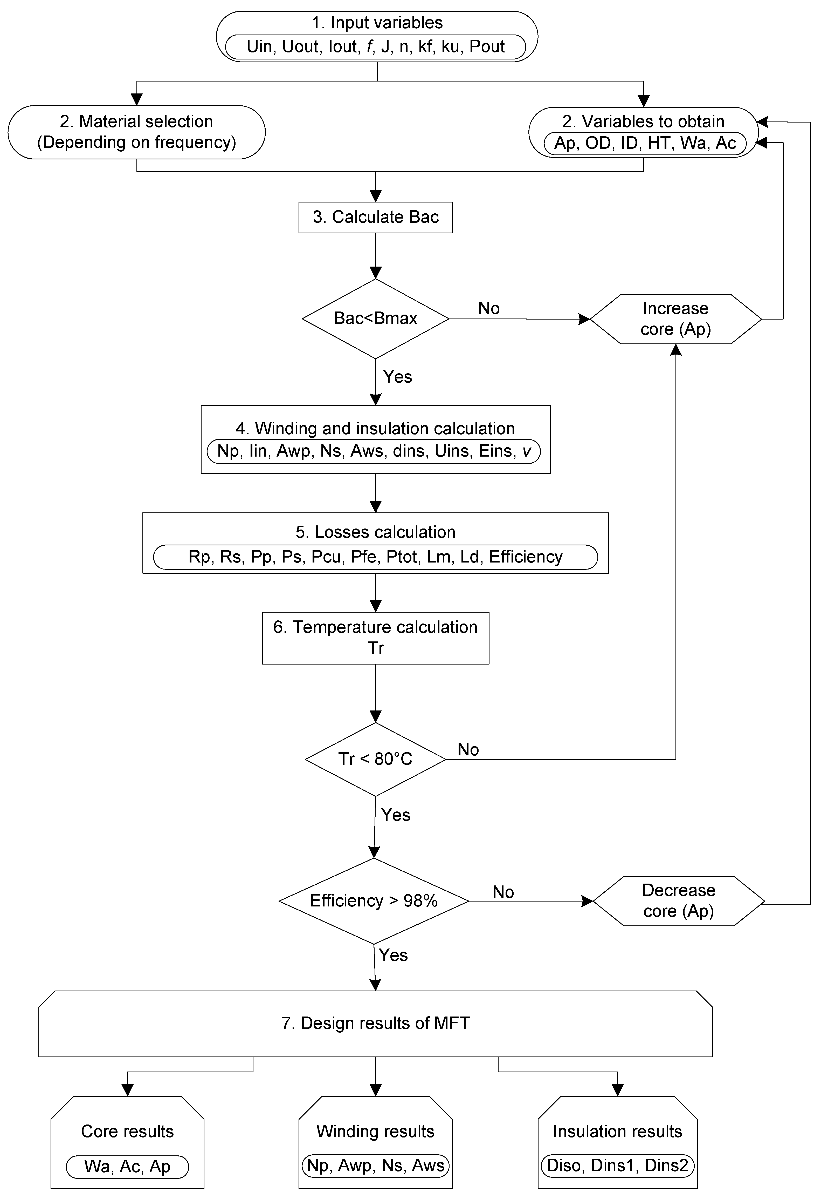
Figure 2 presents the flow diagram of the proposed design process. After this process is completed, the parameters for the MFT design are determined.
As the first step, the initial values of variables, such as input and output voltage (Uin and Uout, respectively), output current (Iout), frequency (f), current density (J), turns ratio (n), waveform coefficient (kf), window utilization factor (ku), and output power (Pout) are chosen.
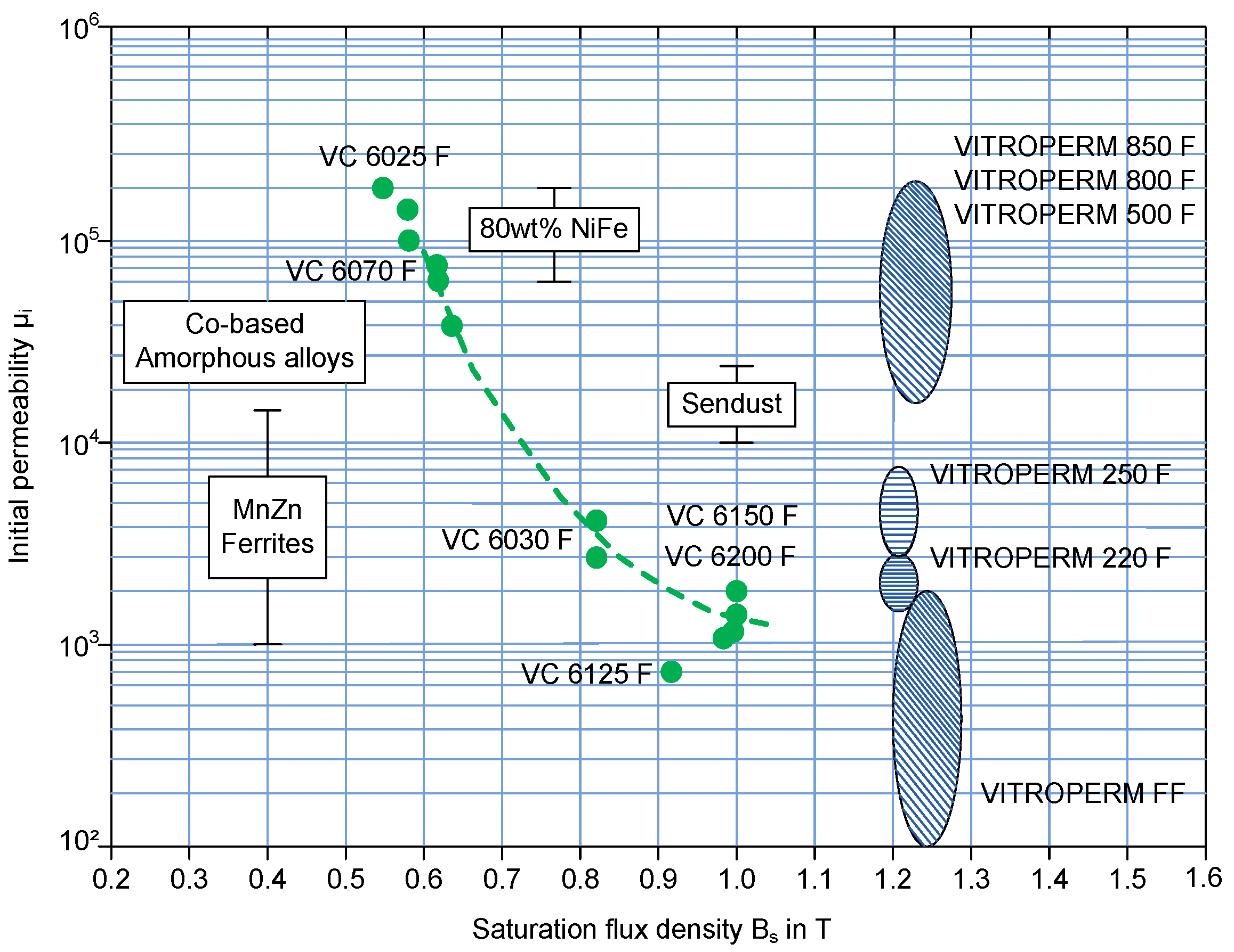
The second step is the selection of the core material, according to the required nominal operation frequency. For the purpose of this work, the frequency is 5 kHz and the core is nanocrystalline.
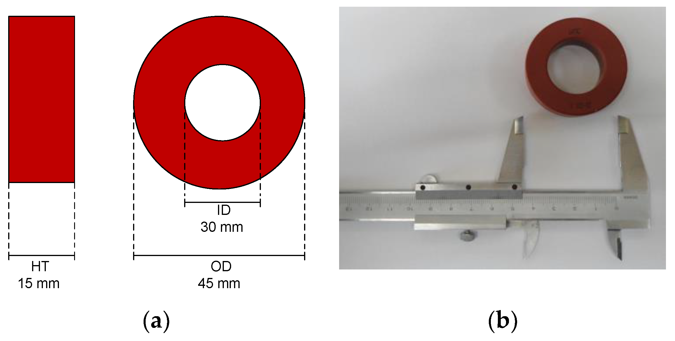
The third step is the computation of the physical dimensions of the MFT core, which include the outer diameter (OD), inner diameter (ID), core length (HT), window area (Wa), effective cross-section of the core (Ac), and the area product (Ap). With the physical dimensions at hand, the flow density (Bac) is then computed. If Bac > Bmax (maximum allowable flow density), then Ap is incremented, and steps 2 and 3 are repeated.
Step 4, reached once Bac < Bmax, is the computation of the winding and insulation characteristics. This calculation involves the primary turns (Np), secondary turns (Ns), primary wire area (Awp), secondary wire area (Aws), input current (Iin), minimum distance between conductors (dins), required insulation voltage (Uins), insulation dielectric rigidity (Eins), and safety margin (v).
In step 5, the main variables needed for determining the efficiency of the MFT are calculated. These are the primary windings resistance (Rp), the secondary windings resistance (Rs), the primary windings losses (Pp), the secondary windings losses (Ps), the copper losses (Pcu), the core losses (Pfe), total losses (Ptot), the magnetization inductance (Lm), and the dispersion inductance (Ld).
The calculation of the temperature (Tr) increase is carried out as step 6. If Tr > 80 °C, then Ap is increased, and steps 2, 3, 4, and 5 are recalculated. If Tr < 80 °C, then the required minimum efficiency is verified. Nanocrystalline materials can withstand temperatures between 105 °C and 120 °C, depending the specific material, which is the reason of choosing the reference set point at Tr = 80 °C.
If the resulting efficiency is lower than 98%, then the goal is not achieved. Therefore, Ap is decreased, and steps 2, 3, 4, 5, and 6 are recalculated. On the other hand, if the resulting efficiency is greater than 98%, then the goal is achieved, and step 7, as well as the design procedure altogether, is over.
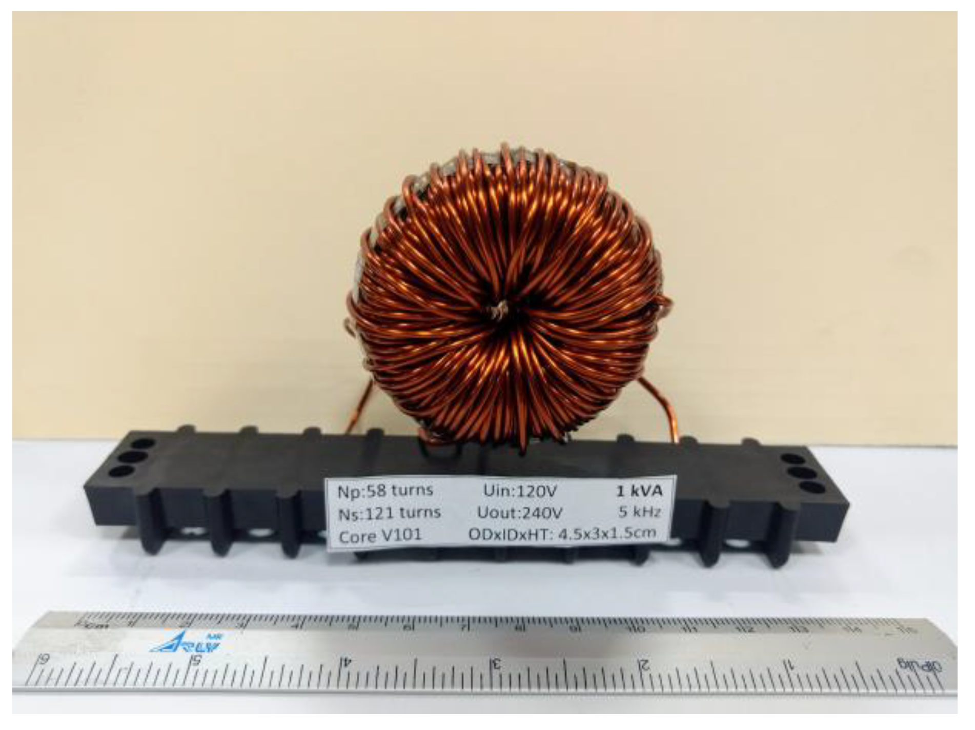
All of the results obtained from the design procedure are organized into core dimensions (Wa, Ac, Ap), winding characteristics (Np, Awp, Ns, Aws), and insulation dimensions. Additional data include the distance between primary and secondary windings (Diso), the minimum insulation distance between primary conductors (Dins1), and the minimum insulation distance between secondary conductors (Dins2). Using these data, the MFT behavior is simulated in Matlab-Simulink (The MathWorks, v2014a, Mexico City, Mexico). Afterwards, the MFT lab prototype is built.

2.2.1. Core Geometry

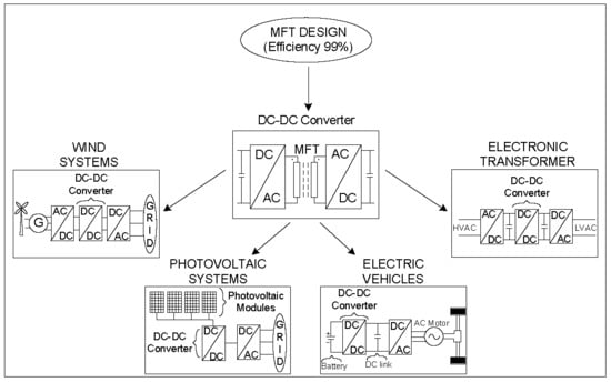
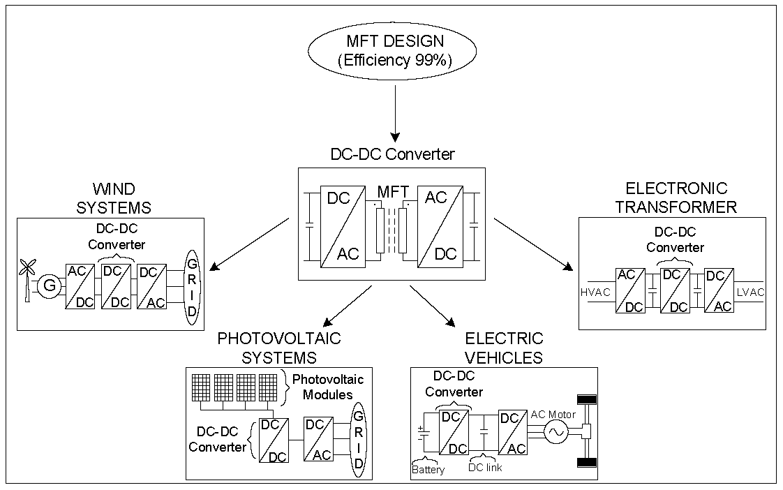
The DAB, toroidal-core, high/medium-frequency transformers have a great opportunity niche in modern power electronics structures. An example of this is the DAB. The main advantages of this type of transformer are the reduction of its weight and volume, as well as obtaining a very low magnetic dispersion flow compared to transformers with different core geometries. In medium-power applications of a DAB converter to power grids, such as an electronic transformer for medium- and low-power grids, high-power density and high transformer efficiency are two key criteria of designing MFTs. In this research work, toroidal core geometry was selected.

2.2.2. Insulation Design

The required minimum insulation distance between conductors for dry insulation of the MFT in DABs [14] is
d i n s = U i n s v E i n s
where v, is the safety margin, Eins is the dielectric rigidity of the insulation material, and Uins is the voltage between the conductors to be isolated. If the insulation calculation is wrong, then the total MFT losses can be higher than initially expected, and recalculation must be carried out. The insulation value that is calculated influences the dispersion inductance value, as is shown in Section 2.2.3.

2.2.3. Dispersion Inductance

The classic mathematical approach to calculate the dispersion is Equation (2) [22]. Another approach is to use Equation (3) [24], which includes data such as the dimensions of the core, the windings, and the insulation material. As part of this research work, results obtained from Equation (3) were compared to those from (i) simulations using the finite element method (FEM) and (ii) the classic Equation (2) for a frequency range of 0 kHz to 200 kHz.
The technique outlined in [24] affords greater accuracy than Equation (2). However, at 5 kHz—the frequency of interest in this paper for simulations and the prototype—both techniques provide nearly the same output:
L d = μ 0 M L T p r i m 1 2 N l 1 2 h ω [ d i s o + m 1 d p r i + ( m 1 1 ) d p r i + m 2 d s e c + ( m 2 1 ) d i n s 2 3 ]
L d = μ 0 N L 1 2 h ω m 1 [ M L T i s o m 1 d i s o + M L T p r i ( m 1 1 ) ( 2 m 1 1 ) 6 d i n s 1 + M L T s e c m 1 ( m 2 1 ) ( 2 m 2 1 ) 6 m 2 d i n s 2 + M L T p r i sin ( 2 1 α δ ) 4 α δ 2 ( m 1 2 1 ) + 4 d p r i ( 2 m 1 2 + 1 ) 24 ( sin 2 1 α δ ) 2 M L T p r i α δ 2 ( 4 1 α δ ) ( 2 m 1 2 + 1 ) 8 d p r i ( 1 m 1 2 ) cos ( 2 1 α δ ) 24 ( sin 2 1 α δ ) 2 + M L T s e c m 1 m 2 sin ( 2 2 α δ ) 4 α δ 2 ( m 2 2 1 ) + 4 d s e c ( 2 m 2 2 + 1 ) 24 ( sin 2 2 α δ ) 2 M L T s e c m 1 m 2 α δ 2 sin ( 4 2 α δ ) ( 2 m 2 2 + 1 ) 24 ( sin 2 2 α δ ) 2 + M L T s e c m 1 m 2 8 d s e c ( 1 m 2 2 ) cos ( 2 2 α δ ) 24 ( sin 2 2 α δ ) 2 ]
where
μ 0 = vacuum permeabilitydiso = isolation distance
dins1 = insulation distance between the layers of the primaryNL1 = turns per layer
dins2 = insulation distance between the layers of the secondaryhw = winding height
m1 = number of layers in the primarydpri = thickness of the primary
m2 = number of layers in the secondarydsec = thickness of the secondary
MLTiso = mean length of the isolation distance1 = penetration ratio of the primary, 1 = d p r i δ
MLTpri = mean length turns of primary portion2 = penetration ratio of the primary, 2 = d s e c δ
MLTsec = mean length turns of secondary portion α = 1 + j δ where δ is the skin depth
The calculation of the dispersion inductance of the lab prototype uses Equations (2) and (3). As initially expected, the theoretical and experimental results are almost the same.

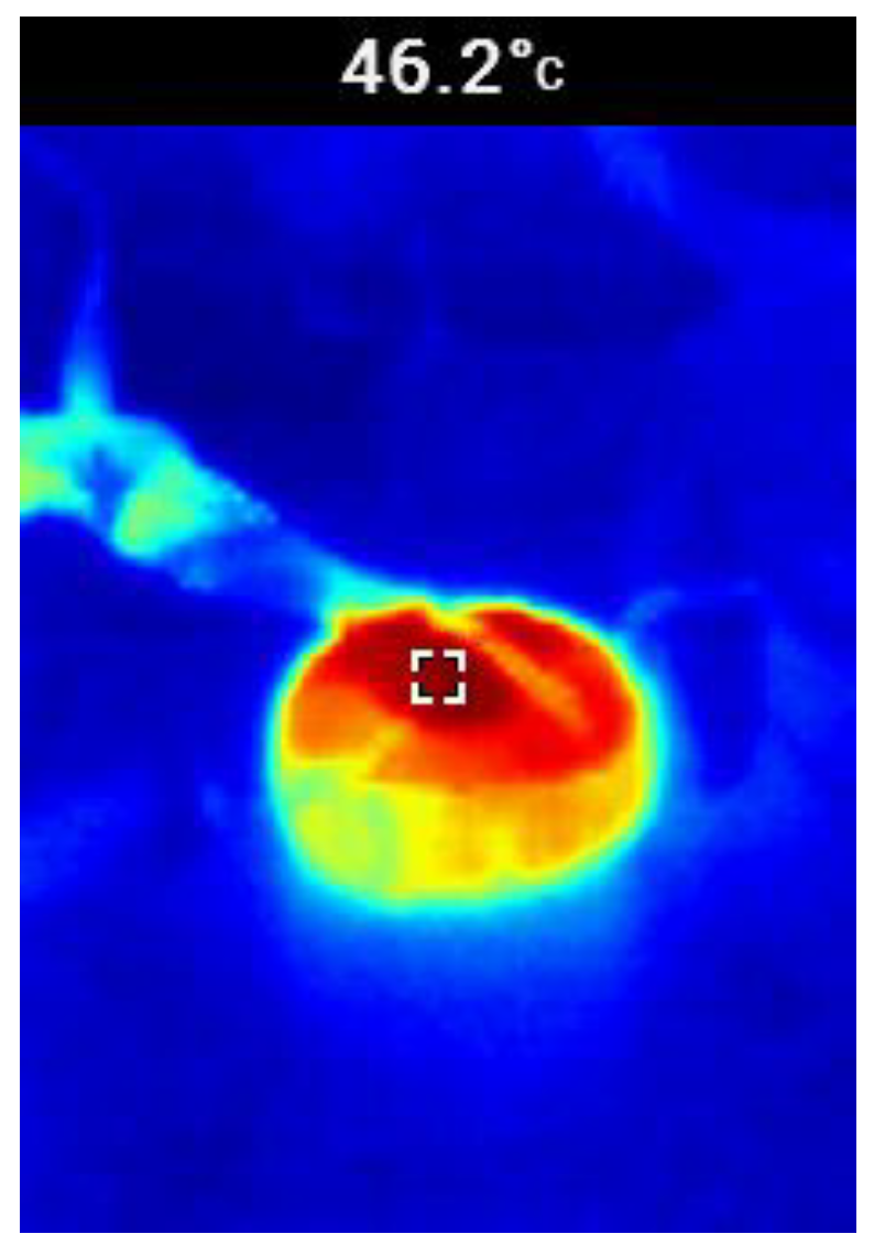
2.2.4. Temperature Increase

The accurate computation of temperature increase in MFTs is crucial for avoiding MFT overheating and damage. The temperature rise is calculated using Equation (4) [22]:
T t = 450 ( P t o t A t ) 0.826
where Tt is the temperature rise in Celsius (°C), Ptot are the total losses in watts, and At is the surface area of the transformer in cm2. Various application examples are well explained in [22].

2.2.5. Winding Losses

The winding losses are calculated with Equations (5–7) [22].
P w i n d i n g = P p + P s
P p = ( I i n ) 2 R p
P s = ( I o ) 2 R s
where Rp and Rs are calculated with Equations (8) and (9), respectively. These are
R p = M L T 1 N p μ Ω / c m 1
R s = M L T 2 N s μ Ω / c m 2
MLT1 and MLT2 are the mean lengths of the primary and secondary windings, respectively; mΩ/cm1 and mΩ/cm2 are the resistances per centimeter of the primary and secondary winding conductors, respectively.

2.2.6. Core Losses

Core losses heavily depend on the core material and the operating frequency of the MFT. At medium frequency (5 kHz), nanocrystalline cores are the common option, because of their low losses and high permeability values. 
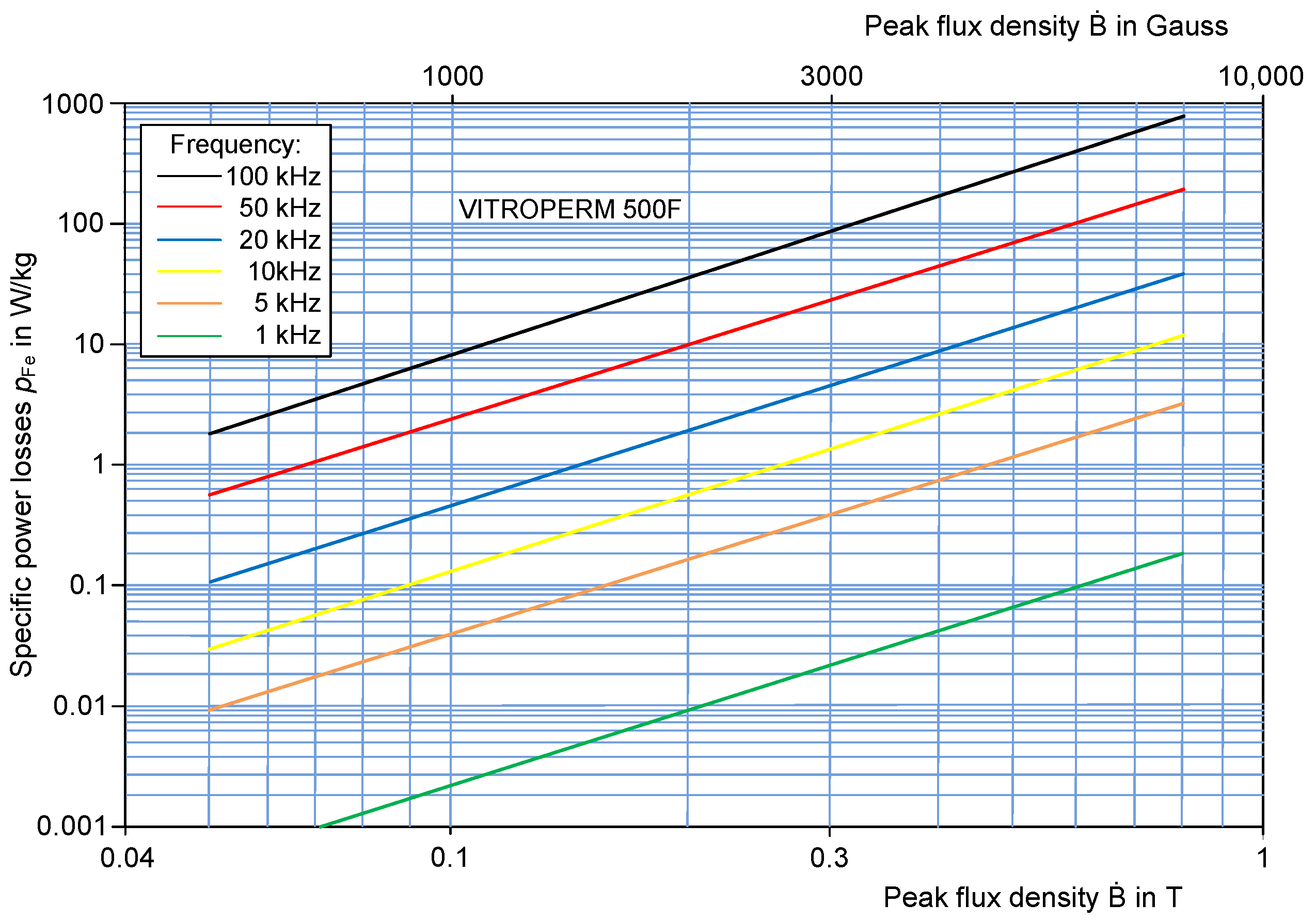
Figure 3 presented the core losses versus flow density relationship for VITROPERM 500F, a nanocrystalline material. Further detailed characterization of the core losses for nanocrystalline materials over a wider range of frequencies is found in [23].
The core losses are calculated with Equation (10):
P f e = ( P f e 1 ) W f e
where Pfe1 are the nanocrystalline material losses (W/kg). In case of VITROPERM 500F, the core losses can be also obtained directly from Figure 3. In the design of the MFT for this work, Pfe1 = 5 W/kg. In this case, Wfe, the core weight (kg), is specified for 1 kVA. It can be noticed that pFe is directly proportional to the frequency and the flow density.

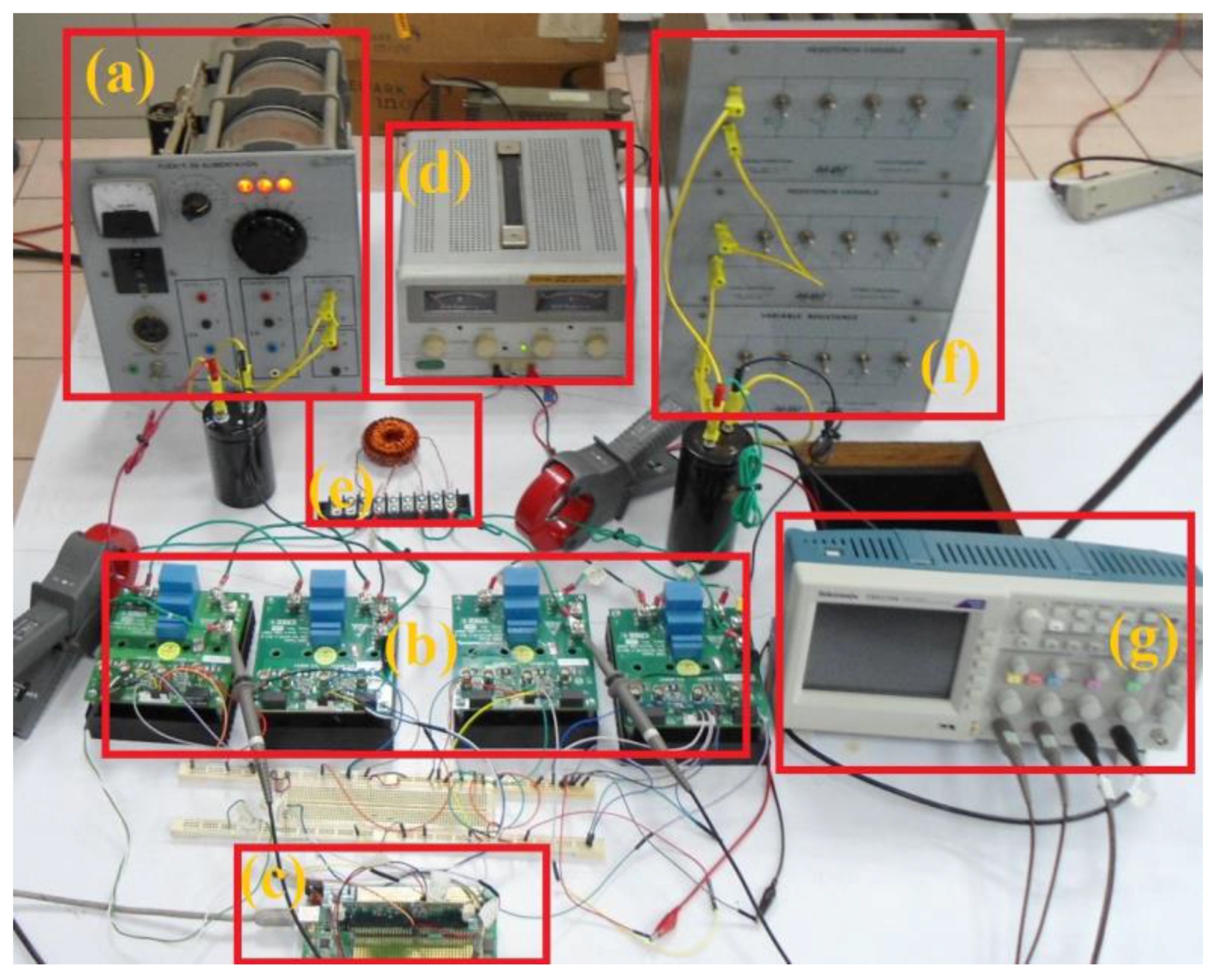
2.3. The Dual Active Bridge Converter and the Medium Frequency Transformer as Prototypes

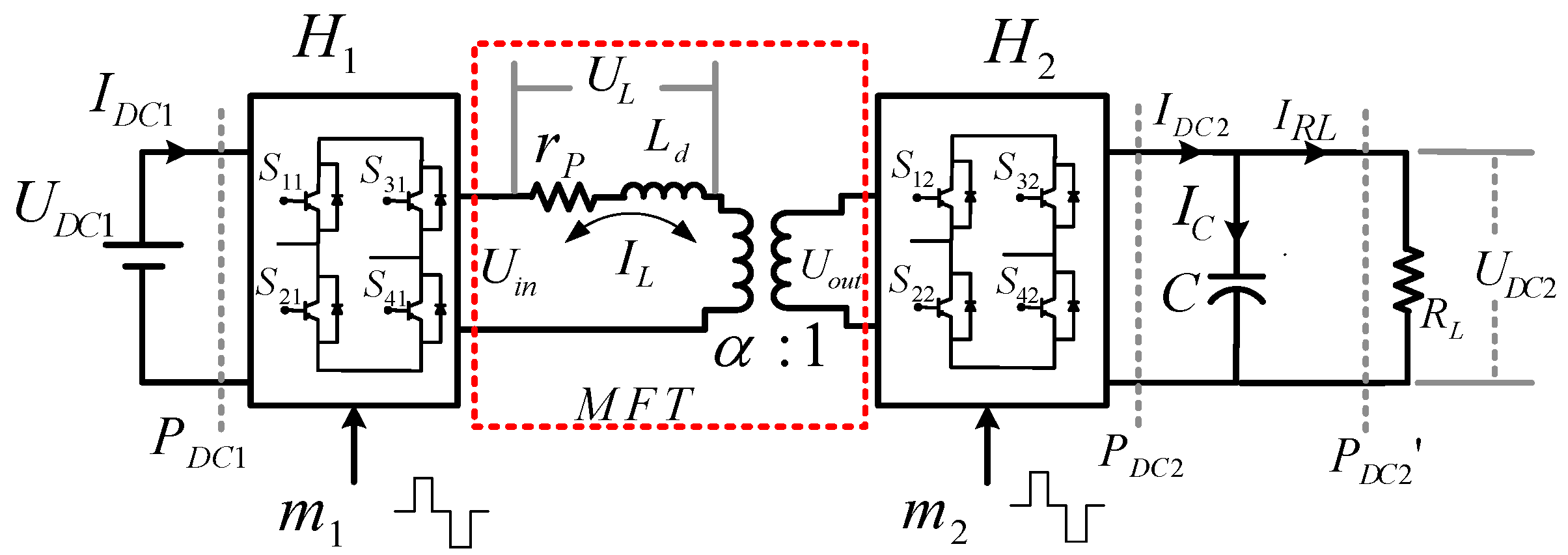
Figure 4 shows the DAB converter topology, where both the input and output ports are each an H-bridge structure (H1 and H2) linked together through a MFT. Uin and Uout are the AC voltages formed by H1 and H2, which in turn rely on the modulation signals m1 and m2, as well as on the DC voltages UDC1 and UDC2, respectively [25]. The voltage difference (UL) between the windings of the MTF produces a current flow IL, which is dependent upon the leakage inductance, Ld, the parasitic resistance, rp, the phase shift carrier (Δφ), and the duty ratio (μ) between the modulation signals m1 and m2. Last but not least, IDC1 and IDC2 represent the DC currents of the H-Bridge converters. Also notice that PDC1 and PDC2 represent the DC powers; more specifically, PDC2’ represents the power dissipated in the resistive load RL.
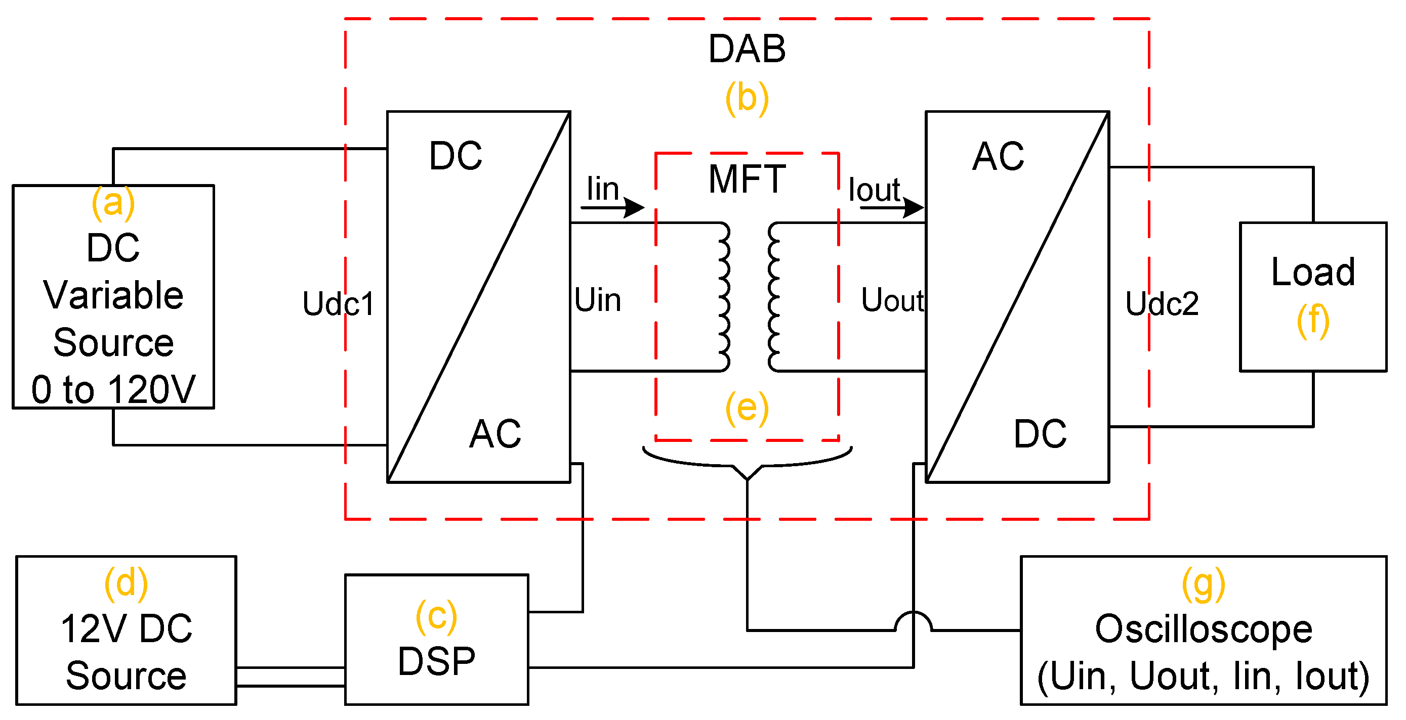
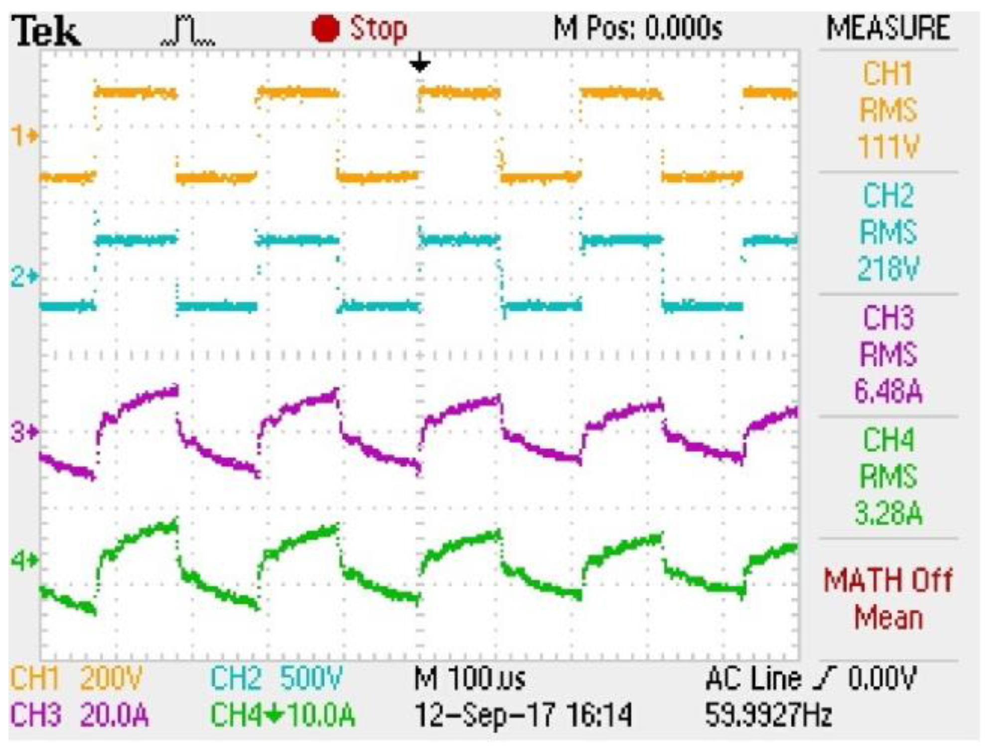
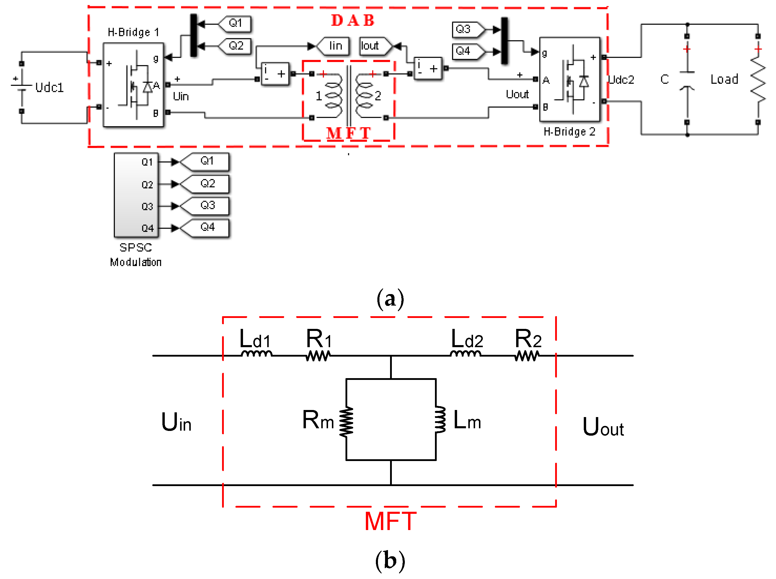
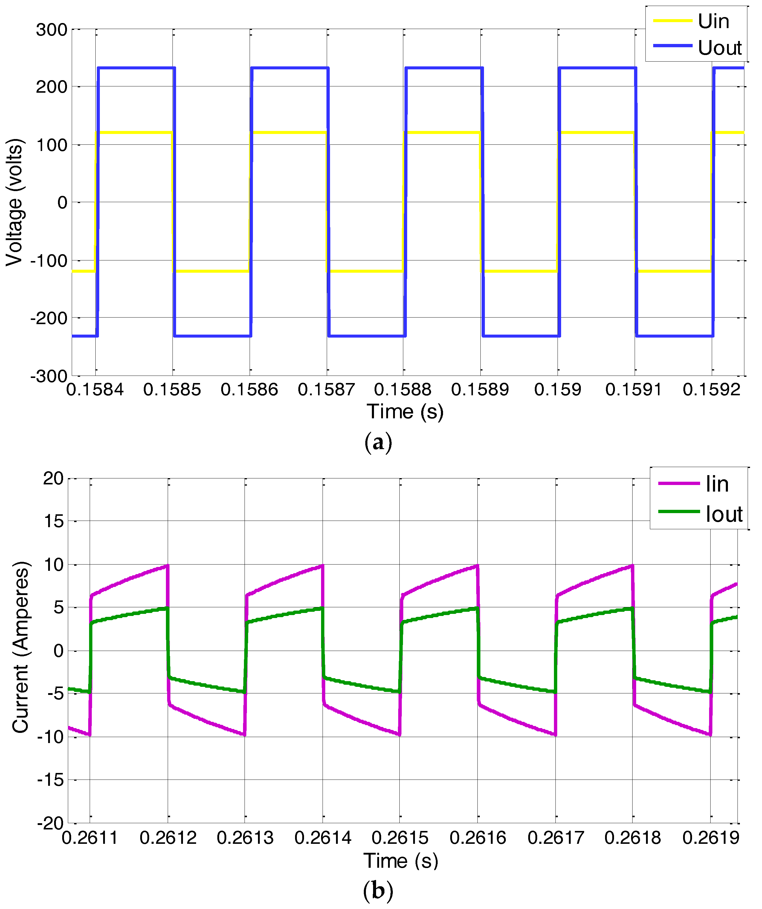
In this paper, the main purpose of the DAB is to help in evaluating the MFT operation, as well as evaluating the overall performance of the DC–DC conversion. The DAB is implemented as a computational model and lab prototype, with the purpose of analyzing the MFT input and output waveforms and MFT efficiency.

3. Design Results

The MFT prototype is designed using the specifications listed in Table 3. A VITROPERM 500F toroidal core is the option for the MFT. From Figure 3 and the technique in [22], the core dimensions obtained are OD = 4.5 cm, ID = 3 cm, and HT = 1.5 cm. Figure 5 illustrates these results.
The number of turns in the MFT primary winding is given by
N p = U i n 10 4 k f B a c f A c
where kf is the waveform factor (4.44 for sine waves and 4.0 for square waves). Due to the square waveform output of the DAB, for this design kf = 4.0. Bac is the flow density obtained with Equation (12). Ac is the transversal section area of the toroidal core [22], and f is the operating frequency of the MFT.
B a c = P t 10 4 k f k u J f A p
In Equation (12), Pt is the total MFT power, Ku is the use factor, J is the current density, and Ap is the product between the transversal section area (Ac) and the window area (Wa).
The number of turns on the secondary winding is obtained with Equation (13):
N s = N p U o u t U i n
Another relevant parameter for the MFT design is the dispersion inductance. The value of this parameter can be obtained using Equations (2) or (3). The comparison of the dispersion inductance obtained with each equation is shown in Table 4.
The difference between the results is 6.23% at 5 kHz. As Equation (3) provides better accuracy than Equation (2) [24], the former equation is the one selected in this paper. Table 5 shows the final results of the MFT design procedure.
The core losses in Table 5 are far lower than the winding losses. The core losses have only a 4.99% share of the total losses. This is due to the high permeability of the nanocrystalline cores (VITROPERM 500F). The resulting efficiency is 99.23%.

4. Simulations

The proposed MFT–DAB system implemented in Simulink-Matlab (The MathWorks, v2014a, Mexico City, Mexico) is shown in Figure 6a, and the internal characteristics of the MFT in Figure 6b. For implementation, the universal bridge component was used for the H-Bridge operation, selecting two arms and Mosfets semiconductor switches. The modulation applied was the single-phase shift carry (SPSC), which is exposed in detail in [26], and the MFT was implemented by the linear transformer component. Finally, the capacitor resistive load and DC sources were used for the complemented circuit.
Table 6 shows the parameters values of the MFT used in the simulations. These parameters are the resistance of the primary (R1) and secondary (R2) dispersion branches, branch magnetization resistance (Rm), branch magnetization inductance (Lm), and branch dispersion inductance (Ld). The values of R1 and R2 are obtained from the areas product method [22]. On the other hand, Rm and Lm are calculated using the common formulations [27], and Ld is calculated with Equation (3).
Figure 7 shows the MFT input and output voltages and currents from simulations. The resulting MFT efficiency is 99.28%. The results from simulations are shown in Table 7.
If the dispersion inductance (Ld) increases, then Uout decreases, due to the presence of a higher dispersion flow. This implies higher losses and a lower efficiency for the MFT. Therefore, Ld must be accurately calculated, in order to obtain experimental results close to the simulation results. The analysis and simulation both result in efficiency higher than 98%.

5. Experimental Results

Figure 8 shows the MFT lab prototype built using the values presented in Table 5.
To test the actual behavior of the MFT lab prototype for DC–DC converters, the MFT was connected to a DAB converter, and the effectiveness of the MFT proposed in this document was tested for the typical square voltage waves that are present in these converters.
Figure 9 shows the experimental setup for testing the MFT–DAB system. This setup includes, the MFT lab prototype, a scaled-down DAB structure, a DSP Texas Instruments (PICOLO S28335), a 66 Ω load, and a CD variable source from 0 to 120 V at 15 A feeding the DAB input. In Figure 10, a block diagram is shown that represents the experimental configuration of Figure 9.
The DC variable source feeds 120 V to the DC/AC module of the DAB converter (Udc1) as shown in Figure 10. Then, the DAB converter supplies a square signal wave (Uin) to the primary winding of the MFT, which is designed as a step-up voltage transformer. As a result, a Uout in the secondary winding of the MFT is obtained. The Uout enters the AC/DC module of the DAB converter in order to obtain a direct current voltage (Udc2), and finally to a 60 Ω load. One of the main objectives of this document is to analyze the MFT behavior before the typical square wave forms of the DC–DC DAB-type converters. For this reason, using the input and output voltages and currents of the MFT (Uin, Uout, Iin, and Iout) with this data, the efficiency of the MFT lab prototype is obtained; the efficiency is one of the main points to know in the MFT, in order to compare it with the obtained simulation results and the mathematical analysis of the proposed design. Figure 11 presents the input and output voltages and the currents from the MFT lab prototype.
As observed in Figure 11, Uin = 111 V, Uout = 218 V, Iin = 6.48 A, and Iout = 3.28 A. Using these data, The MFT lab prototype efficiency is 99.41%. Table 8 shows the experimental results.
Figure 12 shows a thermography of the MFT prototype, taken with a thermal camera (Milwaukee M12TM 7.8 KP). In this case, the maximum temperature was 46.2 °C, which is fairly close to the calculated 46.99 °C. The test was realized at 29 °C room temperature for 1 h.
The efficiency obtained in the MFT lab prototype (99.41%) tested with DC–DC DAB-type converters checked the presented design methodology.
Table 9 presents a comparison of efficiencies obtained from the experiment, simulations, and calculations.
In all three cases, the efficiency achieved was greater than 98%, which is the minimum efficiency specified for the design. The three results support the effectiveness of the design proposed in this document for MFTs with nanocrystalline cores connected to DC–DC DAB-type converters.

6. Discussion

Table 10 shows the efficiency, flow density, and core materials from cutting-edge information available in the open literature about MFTs with a lab prototype. Other proposals available in the literature do not include a prototype or any experimental results; therefore, these are reviewed for this discussion.
Table 10 provides useful information for MFT designers.
The flow density of the design proposed here is 0.9 T. This high flow density results in a high power density. In order proposals, [14,20,21] the flow densities are 0.5 T [14], 0.6 T [20], and 0.35 T [21]. Another investigation [19] presents several designs and prototypes with ferrites and nanocrystalline cores. However, none of these has experimental results incorporating a DC–DC converter.
The design process proposed in this paper is easy to use for MFT designers. The calculations match the simulation and experimental results. The lab MFT–DAB lab prototype has an efficiency of 99.41%. According to the IEEE Std C57.12.01–2015, a dry-type transformer is tagged as efficient if the efficiency is 98% or higher. The MFT, as designed, has various application opportunities in medium voltage grids and microgrids, in areas such as: DC–DC structures, solid-state transformers, photovoltaic systems, wind generators, and power plants, as well as in future interfaces for the smart grid. To take advantage of these opportunities, various technical challenges must be tackled. Examples of these challenges are improvement of the control over the dispersion inductance (increase/decrease) to DC–DC converters requirement, the analysis of MFTs connected to DC–DC converters other than DABs, the evaluation of core losses of different core shape, and performing an MFT analysis using the three-dimensional (3D) finite element method (FEM). Further research interest for this investigation is the integration of MFTs and DC–DC converters to smart grids.

7. Conclusions

New MFT designs are key for developing new DC–DC converters for applications in medium-voltage power grids. To progress in this direction, various challenges in the design and implementation of MFTs must be overcome. One of the challenges in the design process is dealing with the large number of parameters and restrictions, as well as coordinating all together in a comprehensive way. This paper introduces an easy-to-use design procedure for MFTs. This proposal uses the experience of the product-of-the-areas technique, but featuring a crucial modification in the way core losses are calculated. In addition, to improve the areas-product technique, the design process is supported with detailed mathematical analysis, which is verified by computer simulations and data from lab experimentations with a 1 kVA/5 kHz, nanocrystalline-core MFT–DAB prototype. Based on the analytical, simulation, and experimental MFT results, it can be stated that efficiencies greater than a 99% are realizable in the short term.
Comparing this proposal against the latest published research papers, the MFT implemented in this work has a higher power density (15.01 kW/l) than other proposals. This is one of the main goals of the MFT design procedure. To the best of the authors’ knowledge, the MFT–DAB lab prototype performance and efficiency is also better than previous research papers in the open literature; based on the results presented in this paper, it is our honest opinion that the proposed design is a step ahead in the search for new, highly efficient DC–DC converters that require high power density transformers.

Author Contributions

Performed prototype experiments, D.R.-R.; Proposed the idea and supervised the research, V.V.-R. and E.L.M.-G.; Gave technical support and conceptual advice, A.A.-R. and J.R.R.-R.; Wrote the paper, D.R.-R., A.A.-R. and J.R.R.-R.; all authors contributed to the review of the paper.

Funding

This research received no external funding.

Acknowledgments

The authors thanks to the TNM (Tecnológico Nacional de México/Instituto Tecnológico de Morelia) and CONACYT for supporting our research and projects leading to the writing of the present paper.

Conflicts of Interest

The authors declare no conflicts of interest.

References

  1. Sathishkumar, P.; Himanshu; Piao, S.; Khan, M.A.; Kim, D.-H.; Kim, M.-S.; Jeong, D.-K.; Lee, C.; Kim, H.-J. A Blended SPS-ESPS Control DAB-IBDC Converter for a Standalone Solar Power System. Energies 2017, 10, 1431. [Google Scholar] [CrossRef]
  2. Xiong, F.; Wu, J.; Hao, L.; Liu, Z. Backflow Power Optimization Control for Dual Active Bridge DC-DC Converters. Energies 2017, 10, 1403. [Google Scholar] [CrossRef]
  3. She, X.; Huang, A.Q.; Burgos, R. Review of Solid-State Transformer Technologies and Their Application in Power Distribution Systems. IEEE J. Emerg. Sel. Top. Power Electron. 2013, 1, 186–198. [Google Scholar] [CrossRef]
  4. Huang, P.; Mao, C.; Wang, D. Electric Field Simulations and Analysis for High Voltage High Power Medium Frequency Transformer. Energies 2017, 10, 371. [Google Scholar] [CrossRef]
  5. Yang, Q.; Su, P.; Chen, Y. Comparison of Impulse Wave and Sweep Frequency Response Analysis Methods for Diagnosis of Transformer Winding Faults. Energies 2017, 10, 431. [Google Scholar] [CrossRef]
  6. Bahmani, M.A.; Thiringer, T.; Ortega, H. An Accurate Pseudoempirical Model of Winding Loss Calculation in HF Foil and Round Conductors in Switchmode Magnetics. IEEE Trans. Power Electron. 2014, 29, 4231–4246. [Google Scholar] [CrossRef]
  7. Podoltsev, A.D.; Kucheryavaya, I.N.; Lebedev, B.B. Analysis of effective resistance and eddy-current losses in multiturn winding of high-frequency magnetic components. IEEE Trans. Magn. 2003, 39, 539–548. [Google Scholar] [CrossRef]
  8. Godina, R.; Rodrigues, E.; Matias, J.; Catalão, J. Effect of Loads and Other Key Factors on Oil-Transformer Ageing: Sustainability Benefits and Challenges. Energies 2015, 8, 12147–14186. [Google Scholar] [CrossRef]
  9. Everts, J. Design and Optimization of an Efficient (96.1%) and Compact (2 kW/dm3) Bidirectional Isolated Single-Phase Dual Active Bridge AC-DC Converter. Energies 2016, 9, 799. [Google Scholar] [CrossRef]
  10. Wang, Y.-C.; Ni, F.-M.; Lee, T.-L. Hybrid Modulation of Bidirectional Three-Phase Dual-Active-Bridge DC Converters for Electric Vehicles. Energies 2016, 9, 492. [Google Scholar] [CrossRef]
  11. Smailes, M.; Ng, C.; Mckeever, P.; Shek, J.; Theotokatos, G.; Abusara, M. Hybrid, Multi-Megawatt HVDC Transformer Topology Comparison for Future Offshore Wind Farms. Energies 2017, 10, 851. [Google Scholar] [CrossRef]
  12. Kim, D.-H.; Han, B.-M.; Lee, J.-Y. Modularized Three-Phase Semiconductor Transformer with Bidirectional Power Flow for Medium Voltage Application. Energies 2016, 9, 668. [Google Scholar] [CrossRef]
  13. Li, S.; Gao, G.; Hu, G.; Gao, B.; Yin, H.; Wei, W.; Wu, G. Influences of Traction Load Shock on Artificial Partial Discharge Faults within Traction Transformer-Experimental Test for pattern Recognition. Energies 2017, 10, 1556. [Google Scholar] [CrossRef]
  14. Huang, P.; Mao, C.; Wang, D.; Wang, L.; Duan, Y.; Qiu, J.; Xu, G.; Cai, H. Optimal Design and Implementation of High-Voltage High-Power Silicon Steel Core Medium-Frequency Transformer. IEEE Trans. Ind. Electron. 2017, 64, 4391–4401. [Google Scholar] [CrossRef]
  15. Wang, Y.A.; Xiao, D.M. Prototype design for a high-voltage high-frequency rectifier transformer for high power use. IET Power Electron. 2011, 4, 615–623. [Google Scholar] [CrossRef]
  16. Jafari, M.; Malekjamshidi, Z.; Lei, G.; Wang, T.; Platt, G.; Zhu, J. Design and Implementation of an Amorphous High-Frequency Transformer Coupling Multiple Converters in a Smart Microgrid. IEEE Trans. Ind. Electron. 2017, 64, 1028–1037. [Google Scholar] [CrossRef]
  17. Soltau, N.; Eggers, D.; Hameyer, K.; Doncker, R.W.D. Iron Losses in a Medium-Frequency Transformer Operated in a High-Power DC-DC Converter. IEEE Trans. Magn. 2014, 50, 953–956. [Google Scholar] [CrossRef]
  18. Leibl, M.; Ortiz, G.; Kolar, J.W. Design and Experimental Analysis of a Medium-Frequency Transformer for Solid-State Transformer Applications. IEEE J. Emerg. Sel. Top. Power Electron. 2017, 5, 110–123. [Google Scholar] [CrossRef]
  19. Bahmani, M.A.; Thiringer, T.; Kharezy, M. Design Methodology and Optimization of a Medium-Frequency Transformer for High-Power DC-DC Applications. IEEE Trans. Ind. Appl. 2016, 52, 4225–4233. [Google Scholar] [CrossRef]
  20. Krishnamoorthy, H.; Daniel, M.; Ramos-Ruiz, J.; Enjeti, P.; Liu, L.; Aeloiza, E. Isolated AC-DC Converter Using Medium Frequency Transformer for Off-Shore Wind Turbine DC Collection Grid. IEEE Trans. Ind. Electron. 2017, 64, 8939–8947. [Google Scholar] [CrossRef]
  21. García-Bediaga, A.; Villar, I.; Rujas, A.; Mir, L.; Rufer, A. Multiobjective Optimization of Medium-Frequency Transformers for Isolated Soft-Switching Converters Using a Genetic Algorithm. IEEE Trans. Power Electron. 2017, 32, 2995–3006. [Google Scholar] [CrossRef]
  22. McLyman, C. Power Transformer Design. In Transformer and Inductor Design Handbook; CRC Press: Boca Raton, FL, USA, 2011; ISBN 13: 978-1-4398-3688-0. [Google Scholar]
  23. Hilzinger, R.; Rodewald, W. Rapidly solidified amorphous and nanocrystalline materials. In Magnetic Materials; Publicis Publishing: Erlangen, Germany, 2013; Volume 1, pp. 252–302. ISBN 13: 978-3895783524. [Google Scholar]
  24. Bahmani, M.A.; Thiringer, T. Accurate Evaluation of Leakage Inductance in High-Frequency Transformers Using an Improved Frequency-Dependent Expression. IEEE Trans. Power Electron. 2015, 30, 5738–5745. [Google Scholar] [CrossRef]
  25. Zhao, B.; Song, Q.; Liu, W.; Sun, Y. Overview of Dual-Active-Bridge Isolated Bidirectional DC-DC Converter for High-Frequency-Link Power-Conversion System. IEEE Trans. Power Electron. 2017, 8, 4091. [Google Scholar] [CrossRef]
  26. Rodriguez, J.; Moreno, E.; Venegas, V.; Ugalde, L.; Anaya, G. The Proportional-Values Modulation (PVM), a Technique for Improving Efficiency and Power Density of Bidirectional DAB converters. Electric Power Syst. Res. 2017, 144, 280–289. [Google Scholar] [CrossRef]
  27. Hurley, W.; Wolfle, W. Inductance. In Transformer and Inductor for Power Electronics; John Wiley & Sons Ltd.: West Sussex, UK, 2013; Volume 1, pp. 23–54. ISBN 9781119950578. [Google Scholar]
Figure 1. Permeability vs. flow density for ferrites, amorphous materials (VC), and nanocrystalline materials (VP).
Energies 11 02081 g001
Figure 2. MFT design procedure.
Energies 11 02081 g002
Figure 3. Core losses versus flow density for nanocrystalline materials (VITROPERM 500F) from 0 to 100 kHz.
Energies 11 02081 g003
Figure 4. The dual active bridge (DAB) basic configuration and the MFT.
Energies 11 02081 g004
Figure 5. Toroidal core obtained with the new design process: (a) core dimensions and (b) VITROPERM 500F core.
Energies 11 02081 g005
Figure 6. (a) Simulink diagram of the proposed MFT–DAB system, and (b) internal characteristics of the MFT connected to the DAB.
Energies 11 02081 g006
Figure 7. Simulation results: (a) input (yellow line) and output (blue line) MFT voltages and (b) input and output MFT currents, with the DAB interconnected.
Energies 11 02081 g007
Figure 8. 1 kVA/5 kHz MFT lab prototype.
Energies 11 02081 g008
Figure 9. MF–DAB lab prototype: (a) a DC variable source from 0 V to 120 V, (b) the DAB, (c) DSP, (d) a 12V DC source, (e) the MFT, (f) the load, and (g) the oscilloscope.
Energies 11 02081 g009
Figure 10. Block diagram of the experimental setup.
Energies 11 02081 g010
Figure 11. Uin (CH1), Uout (CH2), Iin (CH3), and Iout (CH4) of the MFT lab prototype connected to a DAB converter.
Energies 11 02081 g011
Figure 12. Thermography of the MFT–DAB lab prototype.
Energies 11 02081 g012
Table 1. Comparison of medium frequency transformer (MFT) designs.
Reference Frequency (kHz)Bac (Teslas)Core MaterialPower (kVA)Efficiency (%)Power Density (kW/l)
[14]10.5Silicon Steel3599.062.96
[19]5-/0.9Ferrite/Nanocrystalline5099.5411.5
[20]0.60.6Silicon Steel0.8991.29
[21]200.35Ferrite1099.229.25
This Proposal50.9Nanocrystalline199.4115.01
Table 2. Estimated costs.
MaterialCost
Ferrites (Mn-Zn)Low (1 CHF)
Amorphous (VC)High (3 CHF)
Nanocrystalline (VITROPERM)High (3 CHF)
Table 3. Parameters values for MFT design.
VariableValue
Output power, Pout1 kW
Input voltage, Uin120 V
Output voltage, Uout240 V
Commutation frequency, f5 kHz
Output current, Iout4.1667 A
Number of Phase1-phase
Core materialNanocrystalline
Core typeToroidal
Table 4. Comparison of dispersion inductance values.
EquationValue
Classic5.72 μH
Proposed in [24]6.1 μH
Table 5. Final MFT design.
VariableValue
Number of phase1-phase
Core typeToroidal
MaterialVITROPERM 500F
Core dimensions4.5 × 3 × 1.5 cm
Number of primary winding turns (Np)58
Number of secondary winding turns (Ns)121
Primary winding caliber12 AWG
Secondary winding caliber15 AWG
Dispersion inductance (Ld)6.1 μH
Flow density (Bac)0.9 T
Temperature increase46.99 °C
Winding losses (Pwinding)7.23 W
Core losses (Pfe)0.38 W
Efficiency99.23%
Table 6. MFT model parameters for simulations.
VariableValue
Pout1000 VA
f5 kHz
Uin120 V
Uout240 V
R10.0449 Ω
R20.1882 Ω
Ld16.1 μH
Ld224.4 μH
Rm49,733 Ω
Lm67.64 mH
Table 7. Simulation results.
VariableValue
Uin120 V
Uout238 V
Iin8.09 A
Iout4.05 A
Efficiency99.28%
Table 8. Experimental results.
VariableValue
Uin111 V
Uout218 V
Iin6.48 A
Iout3.28 A
Efficiency99.41%
Table 9. Efficiency computation comparison: (i) analytic calculation, (ii) simulation, and (iii) experimental value.
EfficiencyValue
Analytic calculation99.23%
Simulation99.28%
Lab prototype99.41%
Table 10. Cutting-edge MFT proposals.
ReferenceMaterialBacValue
This proposalNanocrystalline0.9 T99.41%
Harish 2016, [20]Silicon Steel0.6 T99.00%
Pei Huang 2016, [14]Silicon Steel0.5 T99.06%
Bahmani 2016, [19]Ferrite/Nanocrystalline-/0.9 T99.54%
Asier 2017, [21]Ferrite0.35 T99.22%

